DPWBMS200 - Pump Sussex - Free user manual and instructions
Find the device manual for free DPWBMS200 Sussex in PDF.

User questions about DPWBMS200 Sussex
0 question about this device. Answer the ones you know or ask your own.
Ask a new question about this device
Download the instructions for your Pump in PDF format for free! Find your manual DPWBMS200 - Sussex and take your electronic device back in hand. On this page are published all the documents necessary for the use of your device. DPWBMS200 by Sussex.
USER MANUAL DPWBMS200 Sussex
Progressive Basin/Bath Mixer System

text_image
(a) 28mm WALL STUD FINISHED WALL (0) 32mm NOODING G F H I D E C B ASUSSEX
Product code
DPBMS165
DPBMS200
DPWBMS165
DPWBMS200
Rough-in:
- The in-wall (Body Mixer) is supplied and is to be used in conjunction with this Tapware.
- Secure a nogging 32mm (i) back from the front of the stud. Attach the Wall Body Mixer to the nogging.
- Ensure the Body Mixer mounted is square and parallel between the Wall Studs.
- For the purpose of the illustration, the thickness of the finished Wall coverings is calculated to be 28mm (ii) - See step 1 for rough in configuration.
Product parts
(A) Handle
-(B) Spindle Adapter
(C) Spindle Extention
-(D) Dress Ring
-(E) Spindle
-(F) Supply Post
-(G) Dress Ring (Outlet)
-(H) Set Screw
-(I) Outlet
Plumber note
- Tapware is to be installed by a Licensed Plumber in accordance with AS/NZS 3500:2021
- Recommended working water pressure 300 - 500 Kpa. Maximum water temperature is 65°C
- After installation, ensure that tapware functions correctly without leaks.
- Please ensure a copy of the Installation Instructions are left with the end user for future reference.
Pressure testing
On-site high pressure line testing must be conducted with the Mixer in the closed position. (STATIC TEST ONLY)
Under no circumstances is the Mixer to be opened when exceeding the maximum stated water pressure.
At the completion of the testing, do not relieve any high pressure by opening the Mixer.
Exposing the internals of the Mixer Cartridge to higher than specified water pressures, will void the manufacturer's warranty

ASNZS 3710 2015 LIC. 20051
While we aim to ensure the specifications shown are correct at time of printing. Sussex Tips reserves the right to make modifications without prior notice.
Always use the physical product for accurate measurements. Dimensions are subject to change without notice. All measurements are shown in millimetres. Copyright © Suisse Tenny Sussexans.com a
Rough-in
Step 1
For thinner wall coverings, the Masterfit needs to be set further back to compensate.
For thicker wall coverings the Masterfit needs to be set forward.
Ensure the Noggin set back is measured from the face of the stud.

text_image
80 mm WALL STUD MASTERFIT NOGGING Face of Stud 45 mm 28 mm 32 mm 60 mmRough In Table
| Wall Thickness | Noggin Set Back |
| 32mm | 28mm |
| 30mm | 30mm |
| 28mm | 32mm |
- Waterproofing
Step 3
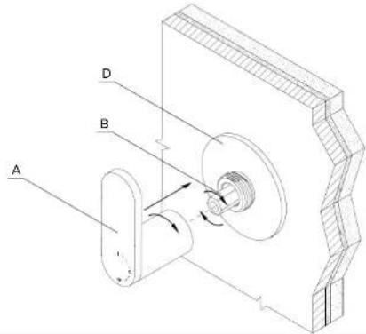
Measure and mark the Spindle Adapter (B) 19mm from the Dress Ring (D).

text_image
D A Bsussextaps.com.au
Fit Off
Step 2
Thread Dress Ring (D) onto Spindle Locknut (E). Tighten Dress Ring (D) with a spanner. Fit the Extension (C) and the Adapter (B) onto the Spindle (E).

text_image
Technical diagram of a mechanical assembly with labeled components A, B, C, D, and EStep 4
Cut and Debum Spindle Adapter (B). Refit adapter onto the spindle.

natural_image
Technical line drawing of a mechanical clamp or bracket assembly with labeled part B (no text or symbols present)Step 5
Ensure the Spindle is set to the 'OFF' position by rotating the Adapter (B) CLOCKWISE. Fit the Handle Assembly (A) with the lever in the upright position. Once engaged rotate the barrel of the handle to tighten against the Dress Ring (D).
text_image
A B DStep 7
If the handle alignment requires adjustment, remove the Handle (A) and Spindle Adapter (B). Rotate (B) to engage a different position on the spindle and refit. Repeat steps 5 and 7 until you reach alignment.

text_image
Technical diagram of a mechanical assembly with labeled components A, B, and Dsussextaps.com.au
Fine Tuning Alignment
Step 6
The handle must be fixed as shown with the "off" position in a vertical alignment.

text_image
Diagram showing three vertical arrangements of cylindrical objects with corresponding red 'X' symbols and a green checkmark indicating selection.Outlet Fit Off
- Fit the Outlet Dress Ring (G) over the Supply Post (F).
- Ensure the O-rings on the Supply Post (F) are lubricated.
- Push Outlet (I) onto Supply Post (F).
- Adjust alignment and secure the outlet by tightening Set Screw (H) with an alen key.
