Unidoor Plus SHEN-2428303436-04 - Door DreamLine - Free user manual and instructions
Find the device manual for free Unidoor Plus SHEN-2428303436-04 DreamLine in PDF.

User questions about Unidoor Plus SHEN-2428303436-04 DreamLine
0 question about this device. Answer the ones you know or ask your own.
Ask a new question about this device
Download the instructions for your Door in PDF format for free! Find your manual Unidoor Plus SHEN-2428303436-04 - DreamLine and take your electronic device back in hand. On this page are published all the documents necessary for the use of your device. Unidoor Plus SHEN-2428303436-04 by DreamLine.
USER MANUAL Unidoor Plus SHEN-2428303436-04 DreamLine
DreamLine® reserves the right to alter, modify or redesign products at any time without prior notice. For the latest up-to-date technical drawings, manuals, warranty information or additional details please refer to your model's web page on DreamLine.com

natural_image
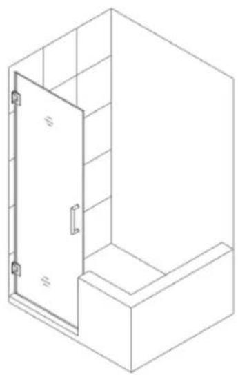
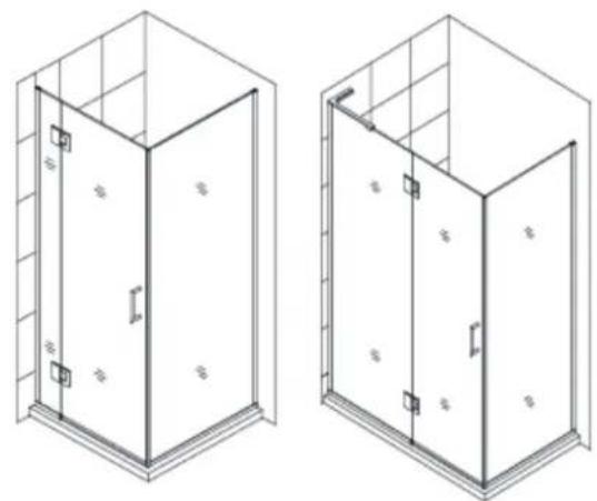
Isometric line drawing of a two-story cabinet or enclosure with doors and windows (no text or symbols)STYLE J
natural_image
Isometric line drawing of a 3D cabinet or enclosure with an open door and side shelf (no text or symbols)STEP 1: INSTALL SHOWER DOOR

natural_image
Isometric line drawing of a cabinet or enclosure with a grid background (no text or symbols)STEP 2: INSTALL PANELS
Please read these instructions carefully before installing. If you have any questions regarding installation, please contact our technical support specialists Monday through Friday 8:00 AM - 7:00 PM EST at Phone: 1-866-731-2244, Fax: 1-866-857-3638 or e-mail our technical support group at Support@DreamLine.com
For more information about DreamLine® products please visit DreamLine.com
DreamLine® reserves the right to alter, modify or redesign products at any time without prior notice. For the latest up-to-date technical drawings, manuals, warranty information or additional details please refer to your model's web page on DreamLine.com

natural_image
Isometric line drawing of a double door mounted on a wall, no text or symbols presentModel #s
SHDR-20237210F-##
SHDR-20247210F-##
SHDR-20257210F-##
SHDR-20267210F-##
SHDR-20277210F-##
SHDR-20287210F-##
SHDR-20297210F-##
SHDR-20307210F-##
## = Finish
01 = Chrome
04 = Brushed Nickel
06 = Oil Rubbed Bronze
HFR=Half Frosted Band
Right-hand installation shown
ATTENTION: This model is also available with the half etched glass option. Please see specific installation instructions on page 15 when applicable.
Please read these instructions carefully before installing. If you have any questions regarding installation, please contact our technical support specialists Monday through Friday 8:00 AM – 7:00 PM EST at Phone: 1-866-731-2244, Fax: 1-866-857-3638 or e-mail our technical support group at Support@DreamLine.com
For more information about DreamLine® products please visit DreamLine.com
UNIDOOR STYLES
Models with Glass-to-Wall hinges

Style A Style B Style C Style D
natural_image
Isometric line drawing of a 3D cabinet or enclosure with no text, numbers, or symbolsStyle E

natural_image
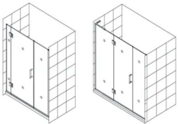
Isometric line drawing of a double door mounted on a grid-patterned cabinet (no text or symbols)Style F

natural_image
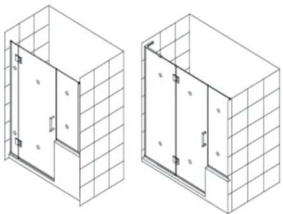
Isometric line drawing of a door opening inside a tiled room (no text or symbols)Style G
natural_image
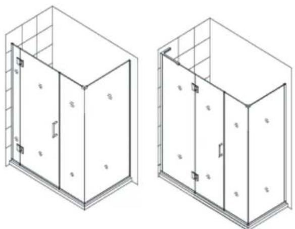
Isometric line drawing of a two-door cabinet or enclosure with doors open, mounted on a shelf (no text or symbols)Style I Style J Style L

natural_image
Isometric line drawing of a 3D cabinet or enclosure with no text, numbers, or symbols
natural_image
Isometric line drawing of a double door cabinet with doors open, mounted on a wall (no text or symbols)Models with Glass-to-Glass hinge panels: For Glass to Glass hinge Door installation use the installation manual packaged with the Hinge panel glass
natural_image
Two isometric line drawings of a two-story indoor enclosure with doors and structural framing (no text or symbols)Style L1

natural_image
Two isometric line drawings of a two-story building with grid walls and doorways (no text or symbols)Style M
natural_image
Two isometric line drawings of a two-story building facade with grid walls and doorways (no text or symbols)Style M1
natural_image
Two isometric line drawings of a two-story building facade with grid walls and doorways (no text or symbols)Style M2
natural_image
Two technical line drawings of a two-story cabinet or enclosure with doors and grilles, shown from different angles (no text or symbols present)Style M3
natural_image
Isometric line drawing of two 3D architectural or structural components with no text or symbols, labeled 'Style M4' below (no other text or symbols)STYLE A
Refer to detailed diagram on page 5 of this manual for assembly instructions
STYLE B \*
UNIDOOR Shower door 23" – 30" with 6" small or 12"-30" large stationary panel
STYLE C \*
UNIDOOR Shower door with 12"-30" large stationary panel
STYLE D \*
UNIDOOR LUX Shower door with 6" small or 14"-30" large stationary panel
STYLE E \*
UNIDOOR LUX Shower enclosure with 30" return stationary panel
STYLE F \*
UNIDOOR PLUS Shower door with 6"-34" in-line stationary panel secured using u-channel
STYLE G \*
UNIDOOR PLUS Shower door with 6"-34" in-line half wall panel secured using u-channel
STYLE I \*
UNIDOOR PLUS Shower enclosure with 6"-34" in-line stationary panel and 30"-34" return panel secured using u-channel
STYLE J \*
UNIDOOR PLUS Shower enclosure with 12"-36" in-line half wall panel and 30"-34" return panel secured using u-channel
STYLE L \*
UNIDOOR PLUS Shower enclosure with 30"-34" return stationary panel secured using u-channel
STYLE L1 \*^
UNIDOOR Z Shower door 23"\~30" with 6" or 24" hinge panel and
with 30"-34" full height return panel secured using u-channel
STYLE M \*^
UNIDOOR Z Shower door 23"\~30" with 6" or 24" hinge panel secured using u-channel
STYLE M1 \*^
UNIDOOR Z Shower door 23"\~30" with 6" or 24" hinge panel and
with 6", 6-1/2", 14", 14-1/2", 22" or 22-1/2" full height inline panel secured using u-channel
STYLE M2 \*^
UNIDOOR Z Shower door 23"\~30" with 6" or 24" hinge panel
with 12", 18", 24" or 26" inline buttress panel secured using u-channel
STYLE M3 \*^
UNIDOOR Z Shower door 23"\~30" with 6" or 24" hinge panel, with 6", 6-1/2", 14", 14-1/2", 22" or 22-1/2" full height inline panel and 30" - 34" full height return panel secured using u-channel
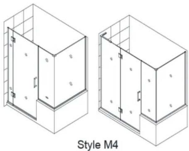
STYLE M4 \*^
UNIDOOR Z Shower door 23"\~30" with 6" or 24" hinge panel, with 12", 18", 24" or 26" in-line buttress panel and 30"- 40" buttress return panel secured using u-channel
* For the panel installation instructions, please refer to the separate manual included in the panel glass packaging.
^ For Glass to Glass door installation, please refer to the separate manual included in the hinge panel glass packaging.
NOTE: The Unidoor series doors and enclosures are reversible for left or right hand installation. This manual will show the right hand installation. For a left hand installation, simply begin on the opposite wall and reverse the orientation of the parts as necessary.
Preparation
- Prior to installation, examine all boxes and packages for shipping damage and compare the piece count with your packing slip. After opening all boxes and packages read this introduction carefully. Check that all of the needed parts are included in the package by checking off the components on the "Detailed Diagram of Shower Door Components". If the unit has been damaged, has a finishing defect, or has missing parts, please contact our customer support department within 3 business days of the delivery date. Please note that DreamLine® will not replace any damaged products or missing parts free of charge after 3 business days or if the product has been installed. Please contact DreamLine® if you have any questions and please provide an order number, job name or other proof of purchase to help identify the original order.
- Please note that you should consult your local building codes with questions about installation compliance standards. Building and plumbing codes may vary by location, and DreamLine® is not responsible for code compliance standards for your project and will not accept any returns.
- If this unit is going to be installed in a new construction, install all of the required plumbing and drainage before installing the shower. Use a competent and licensed (if required by local code) plumber for all plumbing installation.
- Please make sure that prior to beginning the installation, the surfaces are leveled and solid and will be able to support the total weight of the unit. Also make sure the walls are at right angles. Irregular installation surface level, radius corners or improper angle of side walls will result in serious problems for your installation. Please note that some adjustments and drilling may be necessary during the installation process.
- Please protect all primary surfaces of the product during installation. Never set your glass down directly onto a tile floor. Leave corner protectors in place until necessary to remove them. Always use a piece of wood or cardboard to protect the bottom edge and corners of the glass prior to and during installation.
- This unit must be installed upon a finished threshold and against finished walls.
- This door is extremely heavy and the hinges on this door must be attached to the studs or to preinstalled 2" × 6" wood reinforcement behind the wall. See pages 8, 9 & 10 for details.
- The single Unidoor installation does NOT have any adjustment for out-of-plumb conditions. Please verify that your walls are plumb before proceeding with the installation.
- Professional installation is recommended for this heavy glass frameless shower door.
NOTE: DO NOT attach the handle to the door glass until instructed to do so. DO NOT use the handle to lift the glass during installation. This may result in damage to the glass and/or serious injury. Always use an assistant and/or a professional grade glass suction cup when handling heavy glass panels.
Tools Required
Level
Tape Measure

Pencil

Phillips
Screwdriver

Hammer
Drill bit ( =1/4" )

Power Drill

Caulk
Razor Knife
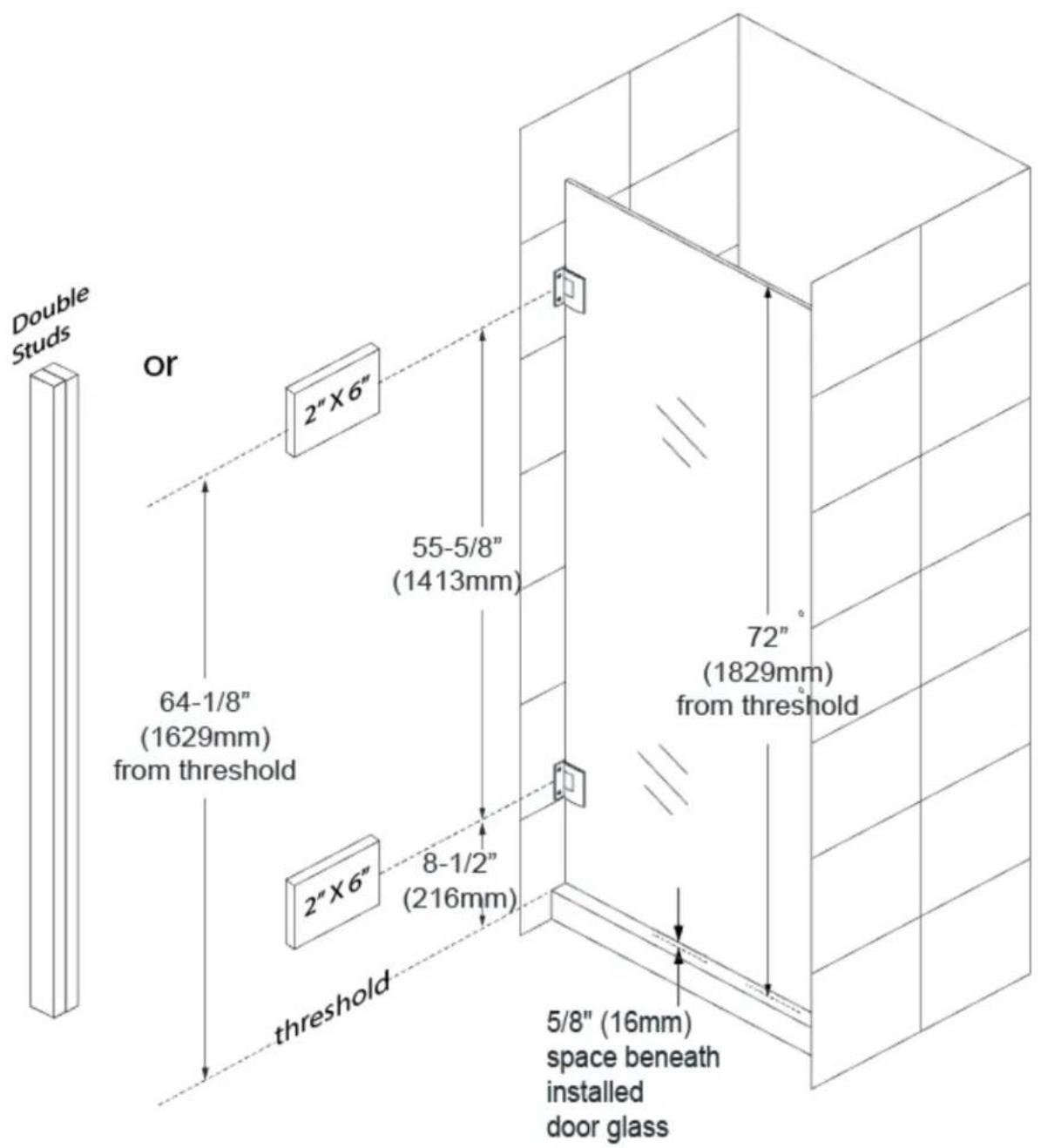
INSTALL DOUBLE STUDS OR INSTALL 2"x6" WOOD BLOCKING BETWEEN THE STUDS WHERE THE HINGES WILL ATTACH TO THE WALL
text_image
Double Studs Or 2" X 6" 64-1/8" (1629mm) from threshold 55-5/8" (1413mm) 72" (1829mm) from threshold 2" X 6" 8-1/2" (216mm) threshold 5/8" (16mm) space beneath installed door glassUNIDOOR GLASS-TO-WALL HINGE AND HANDLE LOCATION

text_image
7-7/8" (200mm) UNIDOOR DOOR GLASS 31-3/4" (806.5mm) 55-5/8" (1413mm) 2" (50mm) handle holes 7-7/8" (200mm) 64-1/8" (1629mm) from threshold 31-3/4" (806.5mm) 72" (1829mm) from threshold 8-1/2" (216mm) 7-7/8" (200mm) GLASS 5/8"SPACE THRESHOLD 5/8" (15.875mm) SPACE 5/8" (15.875mm) SPACEUNIDOOR GLASS-TO-WALL HINGE - HOLE ARRAY
text_image
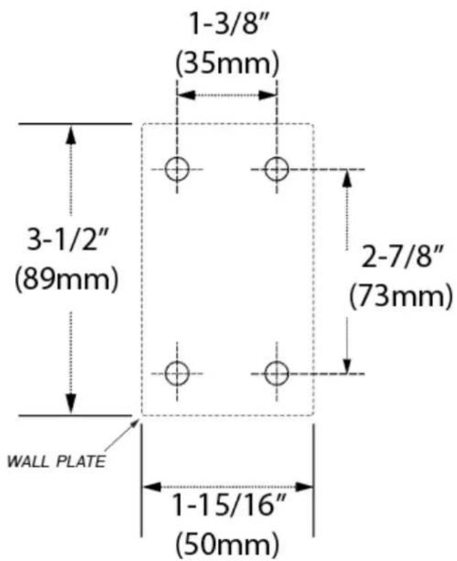
1-3/8" (35mm) 3-1/2" (89mm) 2-7/8" (73mm) WALL PLATE 1-15/16" (50mm)Detailed Diagram of Shower Door Components
text_image
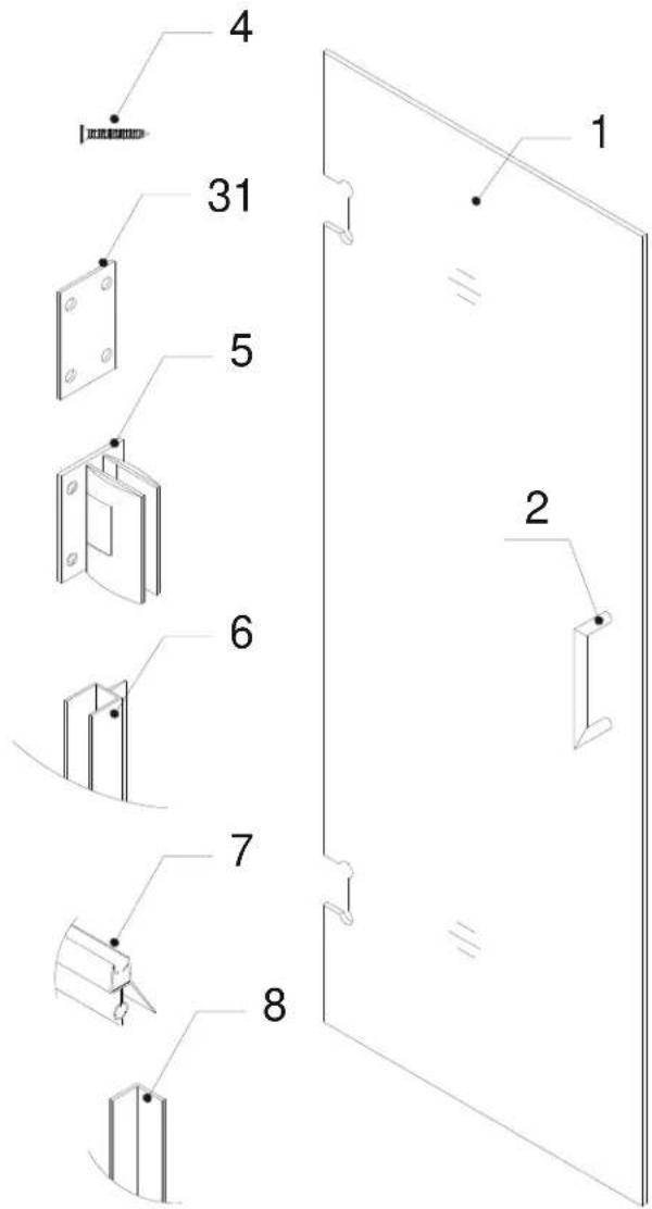
Technical diagram showing eight labeled components of a door panel assembly, with numbered parts and structural details.Packing List
| Part# | Description | Qty | Part# | Description | Qty |
| 01 | Door glass | 1pc | 06 | Side strip ( 3 sections to cut) | 1pc |
| 02 | Handle | 1pc | 07 | Bottom anti-water strip | 1pc |
| 04 | Countersunk screw ST5×70 | 8pcs | 08 | L-shaped strip | 1pc |
| 05 | Hinge with Adjustable angle | 2pcs | 31 | PVC hinge spacer | 4pcs |
NOTE: Unpack your unit carefully and inspect it. Lay out and identify all parts using the detailed diagram and packing list in this manual as a reference. Before discarding the carton, check for small hardware bags that may have fallen to the bottom of the box. If any parts are damaged or missing, please contact DreamLine® for replacement.
Part #8 "L-shaped strip" used with single door installation only.
NOTE: Retain these installation instructions for future reference.
Single Shower Door Assembly and Installation
NOTE: The following shower door installation instructions should be used as a general guide and prerequisite to the installation of the UNIDOOR, UNIDOORLUX and UNIDOOR PLUS models. Before you begin the installation, please check your finished opening size. Specific size information can be found on our website at DreamLine.com
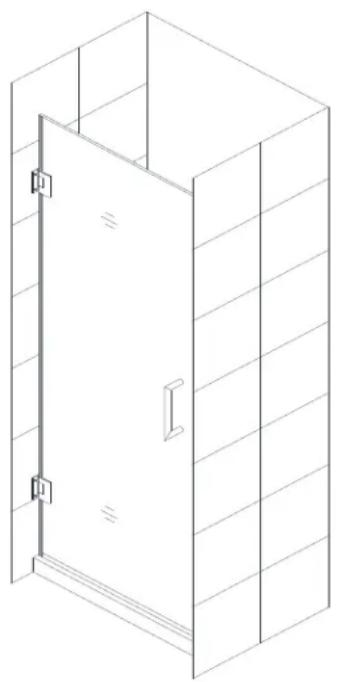
natural_image
Isometric line drawing of a cabinet or enclosure with a door open, no text or symbols presentATTENTION:
This door is extremely heavy and the hinges on this door must be attached to the studs or to preinstalled 2 × 6 wood reinforcement behind the wall.
- Attach the Hinges (05) to the Door Glass (01) using at least one (2mm) vinyl hinge gasket per side.
See Fig. 1 for details.
ATTENTION:
Never set your glass down directly onto a tile or concrete floor.
Always use a piece of wood or cardboard and leave the corner pads and protective shims on the glass until it becomes necessary to remove them to protect the bottom edge and corners from damage which could lead to breakage.

text_image
outside insideFig. 1
ATTENTION:
For Styles E, I, J, K & L that have return panels:
Please check model dimensions for proper placement of the Glass door (01) so that it will align correctly with the return panel glass.
- The Door Glass (01) ships with four 5/8" shims attached to the top (2pcs) and bottom (2pcs). Determine the swing of your door and only remove the shims from the top of the door glass, leaving the bottom shims in place. Set the Door Glass (01) onto the threshold at the desired location and check for level. These 5/8" shims will leave the proper spacing at the bottom of the door glass and will ensure that the door height finishes at 72", but always confirm with a measurement. Carefully butt the door with the hinged side against the wall, adjust its position and check for plumb with a level.
ATTENTION:
Check the door glass with a level to verify that it is plumb before marking the hinge positions.
See Fig. 2 for details.
TIP:
If installing the door along with panel glass, use the 72" Anti-Water strip (Inline) (19) that is packed with the panel glass as a reference to be sure that the door height will match the panel glass at 72".

text_image
5/8" 5/8" shimFig. 2
- Hold the door in place and mark the drill holes for both Hinges (05) on the wall. Set the door aside and drill the holes in the wall using ∅ 1/4" drill bit.
IMPORTANT:
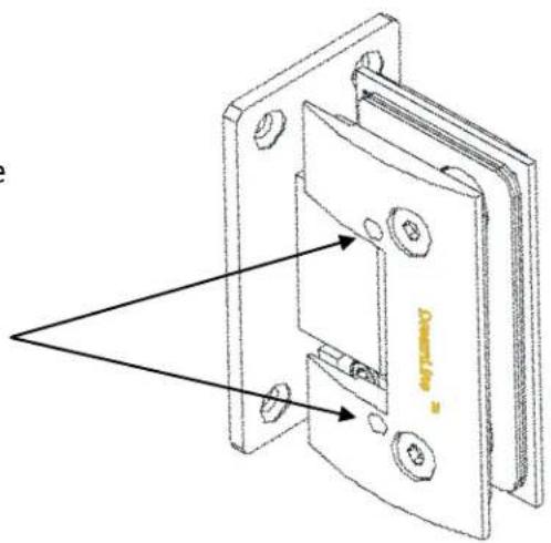
The included PVC hinge spacers (31) are provided to compensate for minor out-of-plumb wall conditions. Use only as needed as their use could compromise the opening size of your shower. Please see Fig 4 for an installation example.
Place the Door Glass (01) back onto the threshold with the 5/8" spacers and attach both hinges to the wall with only two
Countersunk screws ST5×70 (04) on the hinge from outside of the shower. Then open the door and install the remaining screws to the inside of each hinge.
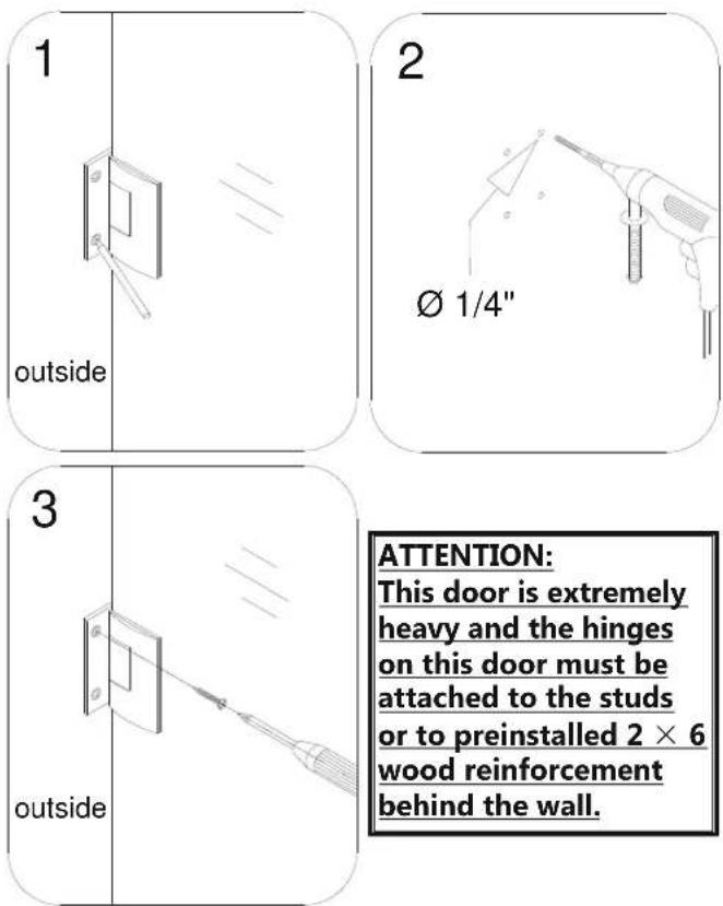
text_image
1 outside 2 Ø 1/4" 3 outside ATTENTION: This door is extremely heavy and the hinges on this door must be attached to the studs or to preinstalled 2 × 6 wood reinforcement behind the wall.Fig. 3
See Fig. 3 and Fig. 4 for details.
TIP: The PVC hinge spacer can also be used as a template to assist with marking the hinge mounting holes.
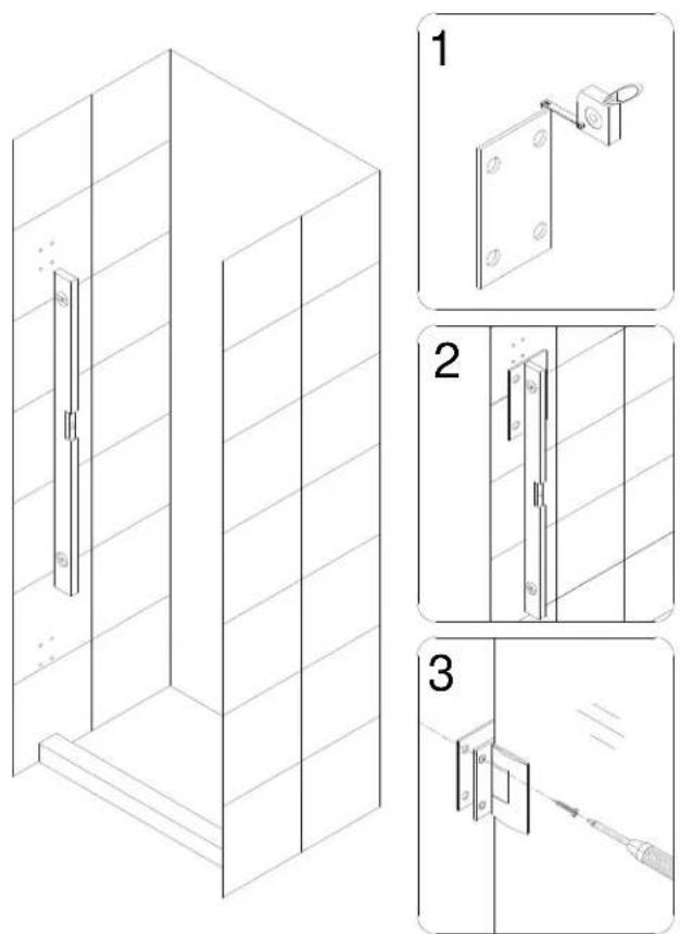
text_image
Technical diagram showing three-step installation of a wall-mounted door panel, with labeled components and exploded views.Fig. 4
ATTENTION:
The back plate of the hinge from inside the shower locates too close to the drilled holes in the wall and might get scratched by the long screws or screwdriver. Be careful not to scratch the hinge surface.
(OPTIONAL)
- Carefully remove back plates from the Hinges (05) and set the Door Glass (01) aside.
Screw in the rest of the Countersunk screws ST5 x 70 (04) into the wall, place the Door Glass (01) with the spacers back to its position and reassemble the Hinges (05). Once the door glass is secure, remove the 5/8" spacers from beneath the Door Glass (01).
See Fig. 5 for details.

text_image
1 inside 2 3 inside 4 insideFig. 5
Setting the Adjustable Hinges
The Adjustable hinges are pre-set to overclose to 85° and are adjustable up to 90° after the door is installed. Once the door glass is installed, simply loosen the allen set screws and position the door to the desired closed position. While holding the door in the new closed position, retighten the allen screws and your door will now self-center to the chosen closed position.
text_image
Technical diagram of a mechanical assembly with labeled components and directional arrows indicating motion or force4a. Make sure the door glass is plumb and the edge of the hinge is installed flush with the glass edge. Center the hinge in the glass notch and tighten the faceplate screws (Figure 5a). Be careful not to scratch the finished surfaces of the hinge during installation.
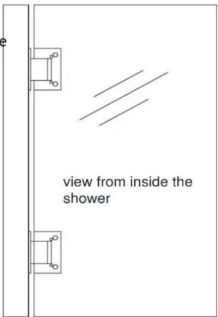
text_image
view from inside the showerFigure 5a
4b. The hinges are factory set to 85 degrees.
You can change this angle by using the adjustment screws on the hinge plate.
(Figure 5b)
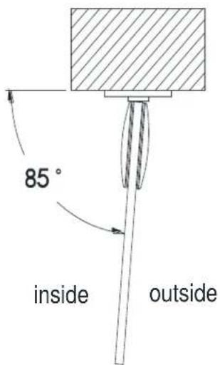
text_image
85° inside outsideFigure 5b
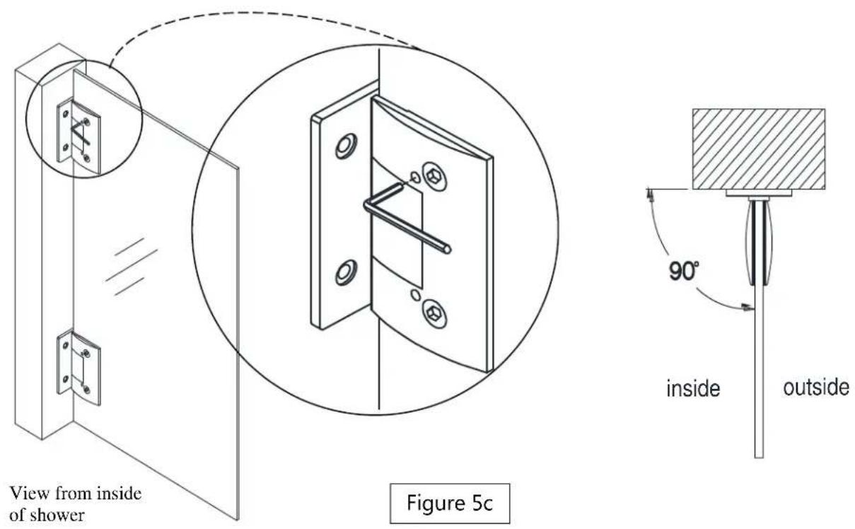
4c. Use the supplied Allen Key to loosen the adjustment screws on the inside hinge plate, adjust the door to the desired angle (90 degrees for example) then retighten the adjustment screws (Figure 5c). Be sure that you create a tight seal with the supplied strike vinyl when the door is in the closed position.
- Mount the Handle (02) to the Door Glass (01).
See Fig. 6 for details.
NOTE: DO NOT attach the handle to the door glass until instructed to do so. DO NOT use the handle to lift the glass during installation. This may result in damage to the glass and/or serious injury. Always use an assistant or a professional grade glass suction cup when handling the door glass.

natural_image
Isometric line drawing of a door frame with a close-up inset showing internal components (no text or symbols)Fig. 6
- Measure the bottom of the Door Glass (01) from end to end to determine the actual width of the door. Cut the Bottom anti-water strip (07) to the size of your measurement and notch 3/8" of the inner side of the Bottom anti-water strip as shown.
Press the Bottom Anti-water strip (07) onto the bottom edge of the Door Glass (01).
NOTICE:
Make sure the Bottom anti-water strip is flush to the vertical edge of the Handle side of the Door Glass.
See Fig. 7 for details.
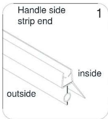
text_image
Handle side strip end 1 inside outside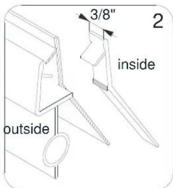
text_image
3/8" inside outside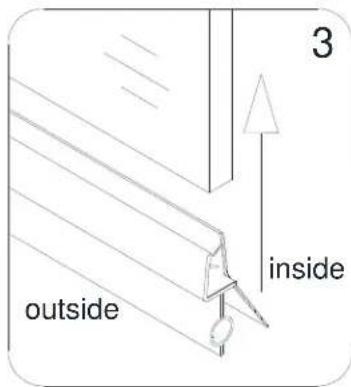
text_image
3 inside outside
text_image
outside inside 4Fig. 7
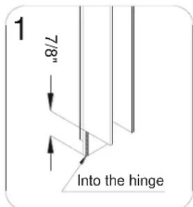
7. Get three measurements:
- from the top edge of the Door Glass (01) to the upper body of the top Hinge (05) (+) 7/8"
- from the lower body of the upper Hinge to the upper body of the bottom Hinge (+) 1-3/4"
- from the lower body of the bottom Hinge to top of the installed Bottom anti-water strip (07) (+) 1-7/8"
Cut the Side strip (06) according to the measurements.
Notch the cut strips to be able to slide them into the Hinge and around the sweep vinyl to cover the space to the wall.
Press the cut strips onto the vertical edge of the Door Glass.
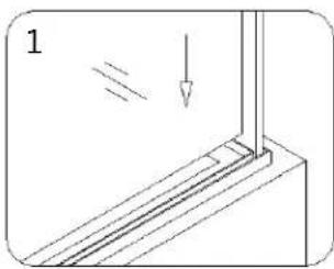
See Fig. 8 for details
text_image
1 7/8" Into the hinge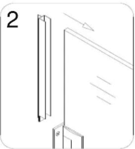
natural_image
Diagram showing two vertical panels with arrows indicating direction, one with a downward arrow and the other with an upward arrow (no text or symbols)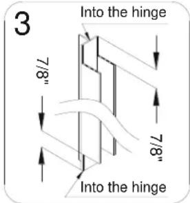
text_image
3 Into the hinge 7/8" 7/8" Into the hinge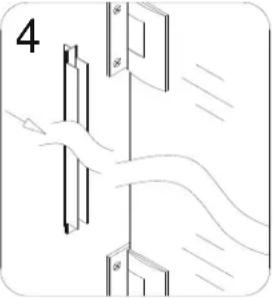
natural_image
Diagram showing hand positioning a door with arrows indicating motion (no text or symbols)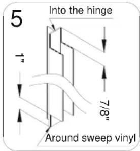
text_image
5 Into the hinge 1" 7/8" Around sweep vinyl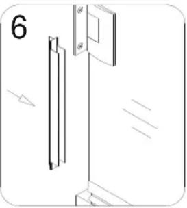
natural_image
Pure technical diagram showing a vertical panel and a door assembly without any text, numbers, or symbolsFig. 8
ATTENTION:
Prior to the next step, please be sure that the section of the wall where you need to attach the L shaped strip (08) is clean, dry and free from soap, oil and any construction debris.
- With the door closed place the *L-shaped strip (08) on the door edge and mark its location on the wall.
Please note that the corner of the L-shaped strip (08) should face inward.
With the door opened, remove the tape backing from the adhesive strip and firmly press the L shaped strip (08) to the wall.
See Fig. 9 and Fig. 10 for details.
\*NOTE:
The above procedure for installing the L-shaped strip (08) is for the Unidoor Style A single shower door installation only. If installing another model with additional panel glass, please refer to the separate glass installation manual located in the glass packaging for model specific instructions. The vinyl seals that apply to the panel glass are packaged with the panel glass.
text_image
1 inside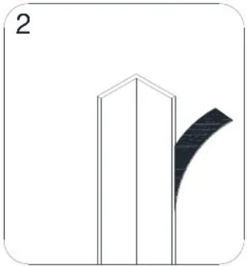
natural_image
Simple line drawing of a building with a curved shadow on the right side (no text or symbols)Fig. 9

natural_image
Isometric line drawing of a single door open in a modular cabinet (no text or symbols)Fig. 10
Style "A":
Half Etched Glass Installation
NOTE: This model features the half etched glass option. Hinged Left installation shown. To install for hinged Right, flip the door to the proper handing.
-The textured surface of the glass door should face out.
See Fig. 11 for details.
natural_image
Diagram showing a transformation of a door frame into a cabinet with directional arrows indicating motion (no text or symbols)Fig. 11
Product Maintenance
BASES and BACKWALLS: To ensure long lasting life for your acrylic back walls: wipe them off after each use with a soft cloth. To clean the acrylic back walls use non-abrasive sprays or cream based cleaners. Avoid the use of aerosol spray cleaners. Never use abrasive cleansers, metal brushes or scrapers that could scratch or dull the surface.
GLASS: To ensure long lasting life for your glass shower products: wipe them off after each use with a soft cloth. Rinse and wipe off the glass using either a soft cloth or a squeegee to prevent soap buildup and water spots (Hard water can etch the surface of the glass over time if left to dry). To prevent scratching the surface: never use abrasive cleaners or cleaning products that contain scouring agents. Never use bristle brushes or abrasive sponges that may scratch the surface.
HARDWARE: To ensure a long lasting finish: wipe off the metal parts after each use with a soft cloth. Do not use abrasive cleaners or cleaning products containing ammonia, bleach or acid. If accidentally used, rinse the surface as soon as possible to prevent damage to the finish (peeling or corrosion). After cleaning the polished finishes, rinse thoroughly and wipe dry with soft cloth. Clean stainless steel surfaces at least once a week. When applying stainless steel cleaner or polish to stainless steel hardware, work with (not across) the grain. Never use an abrasive sponge or cloth, steel wool or wired brush as these may permanently scratch the surfaces.
DREAMLINE® dream in style
TEL: 866-731-2244
FAX: 866-857-3638
DREAMLINE.COM
For more information on DreamLine® Shower Doors and Enclosures please visit DreamLine.com
DREAMLINE® dream in style
UNIDOOR PLUS (STYLE J)
SHOWER ENCLOSURE GLASS PANEL INSTALLATION INSTRUCTIONS
IMPORTANT
DreamLine® reserves the right to alter, modify or redesign products at any time without prior notice. For the latest up-to-date technical drawings, manuals, warranty information or additional details please refer to your model's web page on DreamLine.com
natural_image
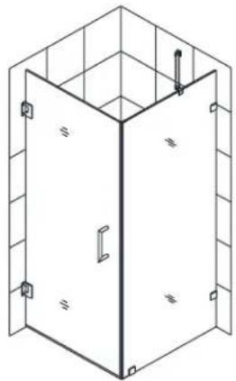
Isometric line drawing of a 3D room corner with vertical walls and a central door (no text or symbols)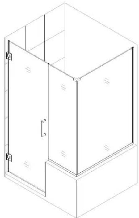
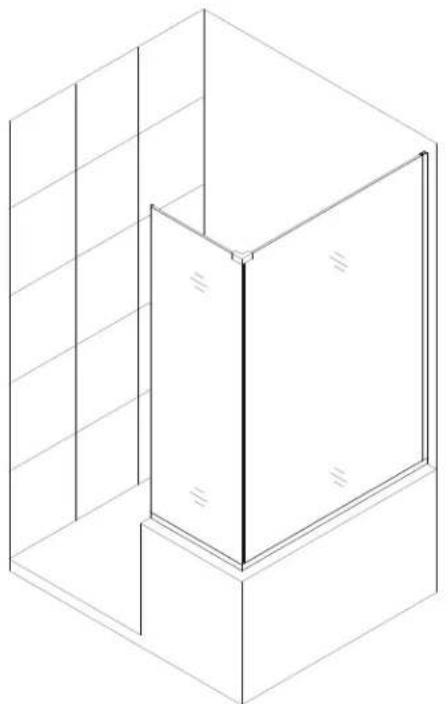
natural_image
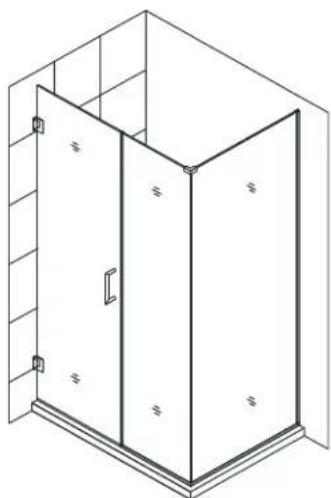
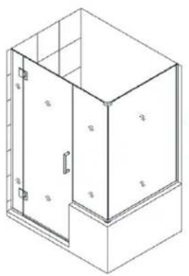
Isometric line drawing of a 3D cabinet or enclosure with no text, numbers, or symbolsRight side panel installation shown
Style J
Please read these instructions carefully before installing. If you have any questions regarding installation, please contact our technical support specialists Monday through Friday 8:00 AM – 7:00 PM EST at Phone: 1-866-731-2244, Fax: 1-866-857-3638 or e-mail our technical support group at Support@DreamLine.com
For more information about DreamLine® products please visit DreamLine.com
Models #s
| SHEN-2423123430 | SHEN-2429183630 | SHEN-2428303430 | SHEN-2424303630 |
| SHEN-2423123436 | SHEN-2429183636 | SHEN-2428303436 | SHEN-2424303636 |
| SHEN-2423123440 | SHEN-2429183640 | SHEN-2428303440 | SHEN-2424303640 |
| SHEN-2423123630 | SHEN-2430183430 | SHEN-2428303630 | SHEN-2423123430 |
| SHEN-2423123636 | SHEN-2430183436 | SHEN-2428303636 | SHEN-2423123436 |
| SHEN-2423123640 | SHEN-2430183440 | SHEN-2428303640 | SHEN-2423123440 |
| SHEN-2424123430 | SHEN-2430183630 | SHEN-2429303430 | SHEN-2423123630 |
| SHEN-2424123436 | SHEN-2430183636 | SHEN-2429303436 | SHEN-2423123636 |
| SHEN-2424123440 | SHEN-2430183640 | SHEN-2429303440 | SHEN-2423123640 |
| SHEN-2424123630 | SHEN-2423243430 | SHEN-2429303630 | SHEN-2424123430 |
| SHEN-2424123636 | SHEN-2423243436 | SHEN-2429303636 | SHEN-2424123436 |
| SHEN-2424123640 | SHEN-2423243440 | SHEN-2429303640 | SHEN-2424123440 |
| SHEN-2427183430 | SHEN-2423243630 | SHEN-2430303430 | SHEN-2424123630 |
| SHEN-2427183436 | SHEN-2423243636 | SHEN-2430303436 | SHEN-2424123636 |
| SHEN-2427183440 | SHEN-2423243640 | SHEN-2430303440 | SHEN-2424123640 |
| SHEN-2427183630 | SHEN-2424243430 | SHEN-2430303630 | SHEN-2427183430 |
| SHEN-2427183636 | SHEN-2424243436 | SHEN-2430303636 | SHEN-2427183436 |
| SHEN-2427183640 | SHEN-2424243440 | SHEN-2430303640 | SHEN-2427183440 |
| SHEN-2428183430 | SHEN-2424243630 | SHEN-2423363430 | SHEN-2427183630 |
| SHEN-2428183436 | SHEN-2424243636 | SHEN-2423363436 | SHEN-2427183636 |
| SHEN-2428183440 | SHEN-2424243640 | SHEN-2423363440 | SHEN-2427183640 |
| SHEN-2428183630 | SHEN-2427303430 | SHEN-2423363630 | SHEN-2428183430 |
| SHEN-2428183636 | SHEN-2427303436 | SHEN-2423303636 | SHEN-2428183436 |
| SHEN-2428183640 | SHEN-2427303440 | SHEN-2423303640 | SHEN-2428183440 |
| SHEN-2429183430 | SHEN-2427303630 | SHEN-2424303430 | SHEN-2428183630 |
| SHEN-2429183436 | SHEN-2427303636 | SHEN-2424303436 | SHEN-2428183636 |
| SHEN-2429183440 | SHEN-2427303640 | SHEN-2424303440 | SHEN-2428183640 |
ADDITIONAL MODEL CONFIGURATIONS for UNIDOOR- X GLASS-TO-GLASS HINGE
natural_image
Isometric line drawing of a 3D cabinet or enclosure with labeled doors and doors (no text or symbols present)Style M4 ^6

natural_image
Isometric line drawing of a two-story cabinet or enclosure with doors and windows (no text or symbols)Style M4 ^24
Model #s
| E124303440-## | E130243640 |
| E124303436 | E130243636 |
| E124303430 | E130243440 |
| E124183640 | E130243436 |
| E124183636 | E130243430 |
| E124183440 | E129243640 |
| E124183436 | E129243636 |
| E124183430 | E129243440 |
| E123303640 | E129243436 |
| E123303636 | E129243430 |
| E123303440 | E128243640 |
| E123303436 | E128243636 |
| E123303430 | E128243440 |
| E123183640 | E128243436 |
| E123183636 | E128243430 |
| E123183440 | E127243640 |
| E123183436 | E127243636 |
| E123183430 | E127243440 |
| E324123440R | E127243436 |
| E324123440L | E127243430 |
| E324123436R | E124303640 |
| E324123436L | E124303636 |
| E324123430R |
| E324123430L |
| E323123440R |
| E323123440L |
| E323123436R |
| E323123436L |
| E323123430R |
| E323123430L |
Preparation
- Prior to installation, examine all boxes and packages for shipping damage and compare the piece count with your packing slip. After opening all boxes and packages read this introduction carefully. Check that all of the needed parts are included in the package by checking off the components on the "Detailed Diagram of Shower Door Components". If the unit has been damaged, has a finishing defect, or has missing parts, please contact our customer support department within 3 business days of the delivery date. Please note that DreamLine® will not replace any damaged products or missing parts free of charge after 3 business days or if the product has been installed. Feel free to contact DreamLine® if you have any questions and please provide an order number, job name or other proof of purchase to help us identify your original order.
- If this unit is going to be installed in a new construction, install all of the required plumbing and drainage before installing the shower. Use a competent and licensed (if required by local code) plumber for all plumbing installation.
- Please note that you should consult your local building codes with questions about installation compliance standards. Building and plumbing codes may vary by location, and DreamLine® is not responsible for code compliance standards for your project and will not accept any returns.
- Please make sure that prior to beginning the installation, the surfaces are leveled and solid and will be able to support the total weight of the unit. Also make sure the walls are at right angles. Irregular installation surface level, radius corners or improper angle of side walls will result in serious problems for your installation. Please note that some adjustments and drilling may be necessary during the installation process.
- Please protect all primary surfaces of the product during installation. Never set your glass down directly onto a tile floor. Leave corner protectors in place until necessary to remove them. Always use a piece of wood or cardboard to protect the bottom edge and corners of the glass prior to and during installation.
- This unit must be installed upon a finished threshold and against finished walls.
- This model requires a minimum 5/8" of flat threshold space for installation.
- This model requires that you drill into the threshold for proper installation.
- This model has 1/2" of adjustment within the u-channel for out-of-plumb wall conditions and overall width within the model size. Confirm the finished opening conditions before proceeding with the installation.
- Professional installation is recommended for this heavy glass frameless shower door.
NOTE: This door is reversible for right or left-hand door installation. The right side panel installation is shown as an example throughout this manual. For a left side panel installation, simply begin on the opposite wall and reverse the orientation of the steps shown.
Tools Required

Detailed Diagram of Glass Panel Components

text_image
13 23 28 8 30 11 26 29 29 9Packing List
| 08 | L-shaped strip * | 1pc | 26 | Return panel glass | 1pc |
| 09 | U-channel 1 (76", wall profile) | 1pc | 28 | Adjustment spacer | 12pcs |
| 11 | Stationary glass | 1pc | 29 | U-channel 2 (44", bottom profile) | 2pcs |
| 13 | ∅5/16" Wall anchor | 28pcs | 30 | 90° Corner Bracket | 1pc |
| 23 | Countersunk screw ST4.2x40 | 28pcs |
NOTE: Unpack your unit carefully and inspect it. Lay it out and identify all parts using the detailed diagram and packing list in your manual as a reference. Before discarding the carton, check for small hardware bags that may have fallen to the bottom of the box. If any parts are damaged or missing, please contact DreamLine™ for replacement. The shipping boxes may contain extra parts not used in your model configuration.
* ATTENTION: L-shaped strip (08) can be found in the glass door packaging and is included in the above Packing List as a reference only. The L-shaped strip (08) installation is shown in step #20 of this manual. NOTE: Retain these installation instructions for future reference.
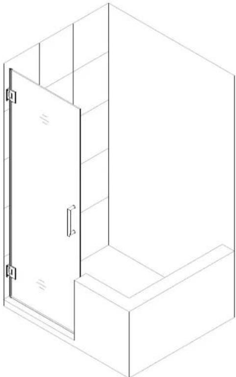
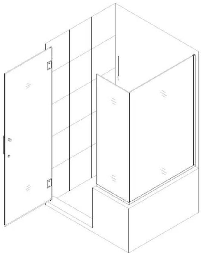
Style "J": In-Line Half Wall Panel with 30"-34" Return Panel Installation
NOTE: The Unidoor shower door needs to be installed prior to proceeding with the following Stationary and Return Glass installation instructions. Please see the Single Shower Door installation manual included in the door packaging for complete shower door installation instructions. Before you begin the installation, please recheck your shower opening size. Specific size information can be found in the “SKU TO GLASS SIZE GUIDE” below and on our website at DreamLine.com.
NOTE: The installation of this enclosure requires two installers.
NOTE: Use parts from "Detailed Diagram of Glass Panel Components" for the glass panel assembly and installation.
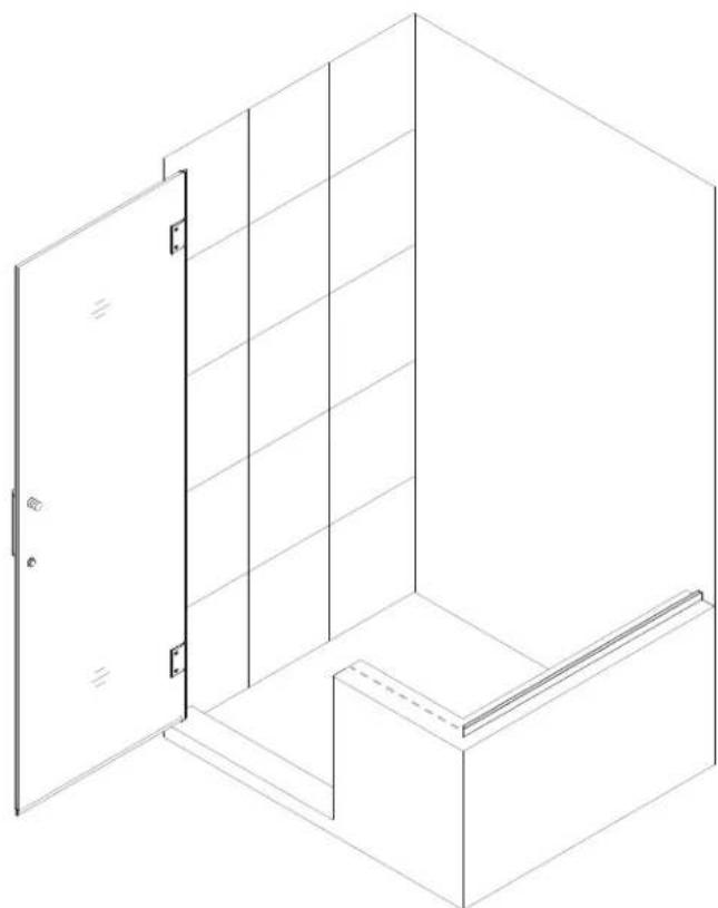
natural_image
Isometric line drawing of a 3D cabinet or enclosure with a door open, showing no text, numbers, or symbols.- Please locate and record the SKU numbers found on the packaging of both glass panels and door. You will specifically need all Product Width and Product Height values to calculate your Shower Enclosure size.
SKU TO GLASS SIZE GUIDE

text_image
Product Width 18" Product Height 34" SHDR-GL2402-183400 Product Line Glass_Model Thickness Code SHEN Shower Enclosure 10mm SHDR Shower & Tub DoorExample
SHDR-GL2402-183400
Unidoor Plus Shower Door Glass Panel 18" x 34" x 10mm.
- Please mark measurement lines on the wall and half wall ledge for the Glass Door and U-channel according to the size of your model.
You will need use the Product Width and Product Height values determined in step #1 in Size Table B.
NOTE: M and L dimensions are from the finished wall to the outside of the U-channel as shown in Fig. 1.
| M = | Door | + | Panel | - | 1/8" |
| L = | Return Panel | + | 7/16" | ||
| I = | 72" | - | Panel Height | ||
Size Table B

text_image
L-1/16" M M Door Panel Return Panel L LFig. 1
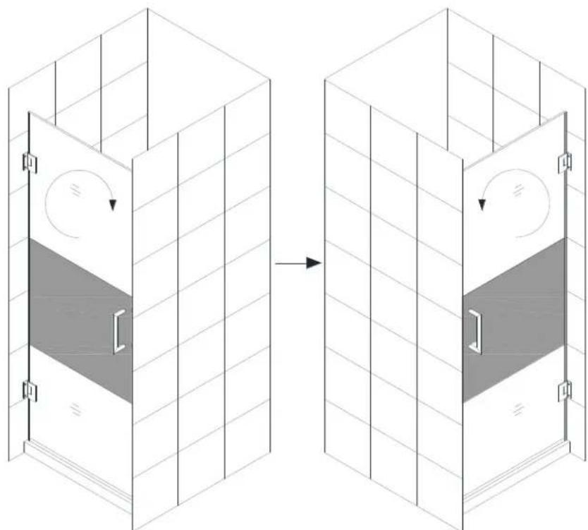
NOTE: The Unidoor hinge is designed to over close 8°. The following procedure is recommended to ensure proper alignment of the panel glass and door.
- Align the Door so that it is perpendicular to the wall and parallel to the threshold. Measure across the bottom span of the Door and threshold on the outside of shower and determine an equal value.
Use a straight edge as guide to mark a line on the half wall ledge on the handle side for future reference.
See Fig. 2 for details.
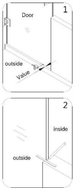
text_image
Door outside Value 1 2 inside outsideFig. 2
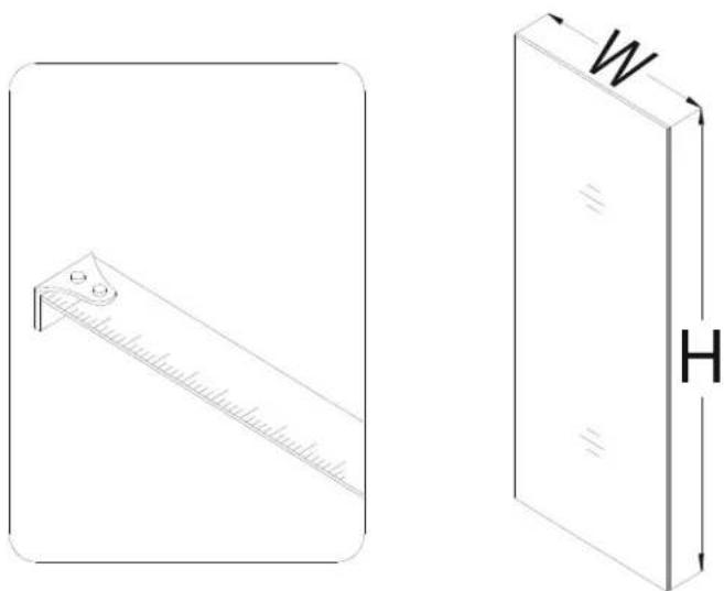
- Measure the actual width and height of your Return panel glass (26).
See Fig. 3 for details.
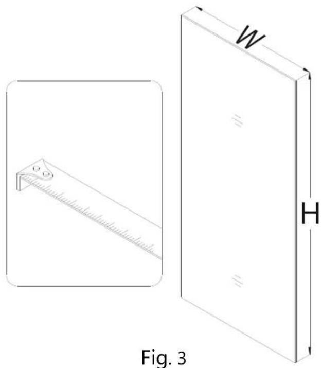
text_image
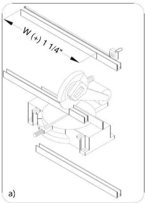
W H Fig. 3- NOTE: You will be doing straight and 45° cuts for this enclosure installation.
*All 45° cuts are from the outside dimension. (tip to tip)
*It may be necessary to remove any burrs from the cut end of the U-channels with a metal file before placing the U-channel onto the glass.
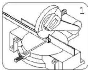
a) Use a miter saw to rough straight cut one of the U-channel 2 (44", bottom profiles) (29) to the actual width of the glass (+) 1 1/4".
b) Use a miter saw to rough straight cut the U-Channel 1 (76", wall profile) (09) to the actual height of the glass (+) 1".
See Fig. 4 & 5 for details.
text_image
W (+) 1 1/4" a)Fig. 4

text_image
H (+) 1" b)Fig. 5
- Slip the cut U-channel 2 (44", bottom profile) (29) and U-channel 1 (76", wall profile) (09) onto the Return panel glass (26) in the shown locations.
With the door open, place the Return panel glass on the half wall ledge adjacent to the door and in line with the wall mark. Adjust the Return panel glass and U-channel 1 (wall profile) against the wall to compensate for any out of plumb conditions ensuring that the Return panel glass is level vertically and the U-channel 1 is flush with the wall.
Mark the U-channel 2 (bottom profile) end opposite of the wall at the exposed vertical glass edge.
Remove the U-channel 2 (bottom profile). Leave the U-channel 1 (wall profile) on the Return panel glass. Set the Return panel glass aside.
Cut the U-channel 2 (bottom profile) 45° to the mark (+) 1/2". The end facing the wall will remain straight.
Slip the U-channel 2 (bottom profile) back onto the Return panel glass and set the Return panel glass aside.

text_image
U-channel 1 U-channel 2 wall Return glass inside 1 2
text_image
inside 3 4
text_image
mark + 1/2" 45° 5 6 insideFig. 6
See Fig. 6 for details.
- Measure the actual width of your Stationary glass (11) panel.
Use a miter saw to cut the second U-channel 2 (44", bottom profile) (29) 45° to the actual width of the glass (+) 1/16".
See Fig. 7 & 8 for details.
natural_image
Technical illustration of a ruler and a rectangular block with labeled dimensions (no text or symbols present)Fig. 7

text_image
W (+) 1/16" 45°Fig. 8
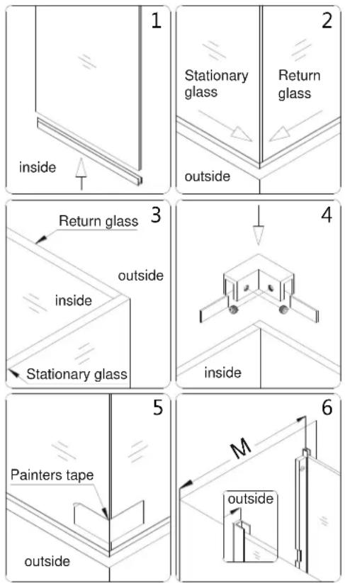
- Slip the U-channel 2 (44", bottom profile) (29) onto the Stationary glass (11) and ensure that the straight end of the U-channel 2 is flush with the vertical glass edge.
Carefully butt the Stationary glass and Return panel glass (26) together while on top of the half wall ledge to form a tight corner from bottom to top. The Stationary glass will be in front of the Return panel glass.
While securely holding the two glass panels, attach the 90° Corner Bracket (30) to the top corner.
Ensure that the 90° Corner Bracket is square and gaskets are aligned properly before tightening the glass holding screws.
Temporarily secure the bottom corner of the glass panels with a generous strip of Painters tape.
Carefully butt the Return panel glass (26) up against the wall vertically according to the M value stated in Size Table B on page 5 and square it up with a level.
See Fig. 9 & 10 for details.
NOTE: Steps #8 and #9 involve careful handling of the glass panels to determine a custom fit measurement unique to your installation. It is essential that two installers be used along with responsive communication once the panels are temporarily fixed together.
Fig. 9

natural_image
Isometric line drawing of a modular cabinet or enclosure with two doors and a side panel (no text or symbols)Fig. 10
NOTE: Intermittently use a level throughout these steps to ensure that this glass enclosure is leveled properly.
- While securely holding the glass panels, close the Glass Door and align the Stationary glass (11) to it. Use the door mark on the ledge as a reference to ensure that the Door is perpendicular to the wall.
NOTE: The top of the Stationary glass must be leveled with the Glass door. By traversing across the top of both the Stationary glass and door, height differences can be measured. The Adjustment spacers (28) are provided to compensate for such differences by inserting them into the U-Channel 2 (bottom profile) (29). Please make note of the spacer size that is needed for your situation.
Ensure that the Stationary glass is level vertically and precisely in line with Door. The U-channel 1 (wall profile) (09) will remain flush against the wall. Outline the position of the glass panels along the inside bottom edge of all U-channels on the ledge and wall.
Mark the U-channel 1 (wall profile) (09) at the top horizontal glass edge. The height of this mark will change if spacers are needed.
See Fig. 11 & 12 for details.
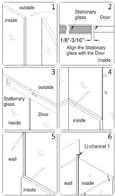
Fig. 11

natural_image
Isometric line drawing of a window or cabinet structure with vertical supports and horizontal beams, no text or symbols present.Fig. 12
- Carefully disassemble the panels for the next steps.
See Fig. 13 for details.
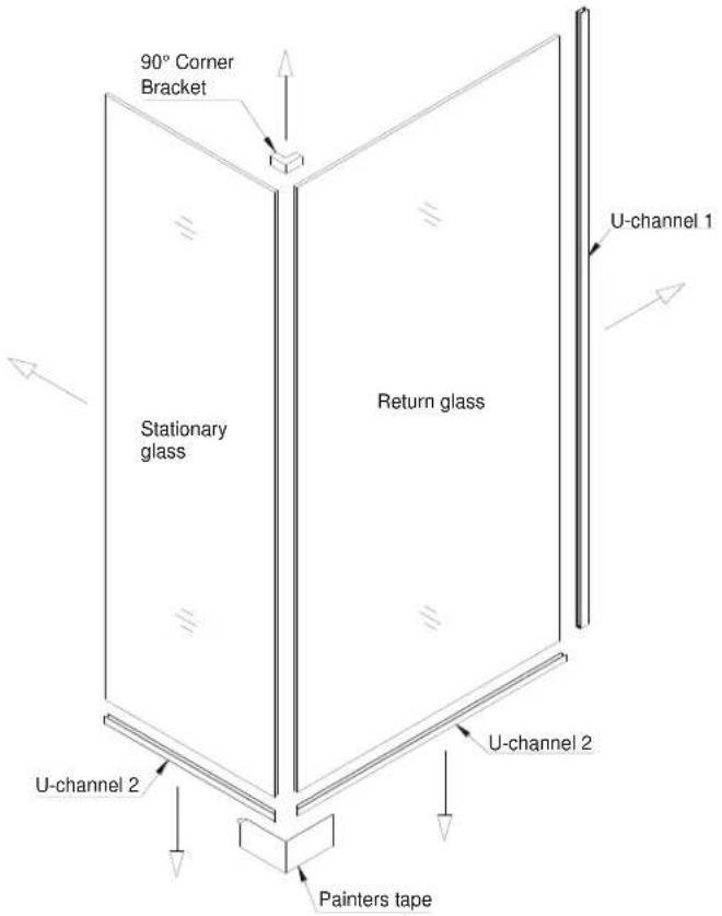
text_image
90° Corner Bracket Stationary glass Return glass U-channel 1 U-channel 2 U-channel 2 Painters tapeFig. 13
- Place the cut U-Channel 2 (bottom profile) (29) for the Return panel glass (26) onto the ledge in line with the inside mark.
Mark the drill holes on the ledge through the predrilled holes in the U-Channel 2 and drill the holes using ∅5/16" drill bit.
Insert the ∅5/16" Wall anchors (13).
Apply waterproof silicone along the bottom surface and around the holes of the U-Channel 2 and fasten it to the ledge with the Countersunk screws ST4.2×40 (23).
NOTE: The surface needs to be clean and free of debris before applying silicone.
See Fig. 14 & 15 for details.
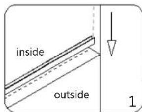
text_image
inside outside 1
natural_image
Technical line drawing of a mechanical assembly with a lever and base plate (no text or symbols)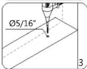
text_image
Ø5/16" 3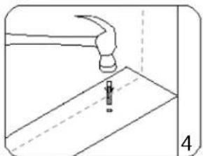
natural_image
Line drawing of a hand using a hammer to press or install a sheet of paper, with no visible text or symbols.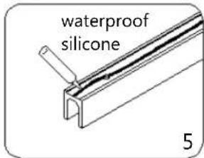
text_image
waterproof silicone 5
natural_image
Technical line drawing of a mechanical assembly with a tool inserted, showing no text or symbolsFig. 14
natural_image
Isometric line drawing of a cabinet with open door and side shelf, no text or symbols presentFig. 15
- Straight cut the U-channel 1 (76", wall profile) (09) at the top mark that was made in step #9.
Place the U-Channel 1 (wall profile) on the U-Channel 2 (bottom profile) (29) and align vertically with the inside wall mark.
Mark the drill holes on the wall through the predrilled holes in the U-Channel 1.
Now drill holes in the wall using ∅5/16 drill bit and insert the ∅5/16" Wall anchors (13).
See Fig. 16 for details.
natural_image
Technical line drawing of a mechanical assembly with no visible text or symbols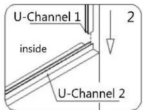
text_image
U-Channel 1 inside U-Channel 2 2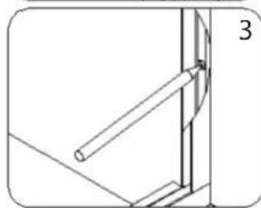
natural_image
Pure technical line drawing of a mechanical assembly without any text, numbers, or symbols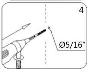
text_image
4 Ø5/16"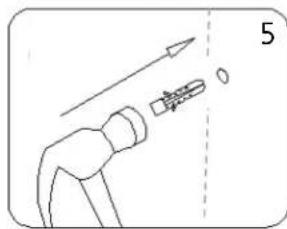
text_image
5Fig. 16
- Apply waterproof silicone along the bottom surface and around the holes of the U-Channel 1 (wall profile) (09). Fasten the U-Channel 1 to the wall with the Countersunk screw ST4.2x40 (23).
Insert the provided Adjustment Spacers (28) into U-Channel 2 (bottom profile) (29) for minor adjustments if necessary. Apply Waterproof silicone into the groove of both U-Channels.
NOTE: The surface needs to be clean and free of debris before applying silicone.
See Fig. 17 & 18 for details

text_image
1 waterproof silicone
natural_image
Technical line drawing of a mechanical component with a tool and dimension lines (no text or symbols)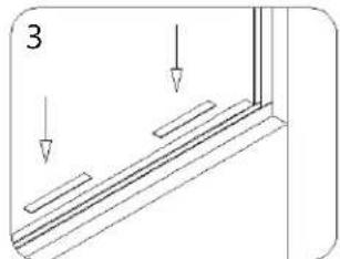
natural_image
Technical diagram showing a structural component with two downward arrows indicating direction (no text or symbols)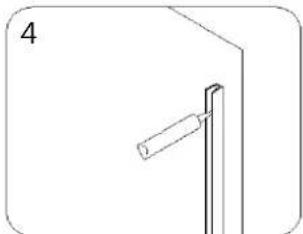
natural_image
Simple line drawing of a vertical pole with a handle, no text or symbols present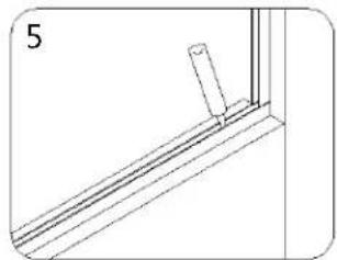
natural_image
Technical line drawing of a window frame with a vertical post and horizontal beam (no text or symbols)Fig. 17
natural_image
Isometric line drawing of a room with a door open, vertical panel, and horizontal shelf (no text or symbols)Fig. 18
- Slide the Return panel glass (26) into the groove of both U-Channels.
NOTE:
If you have difficulty sliding the Return panel glass into the U-Channels, you can slightly tap on the Return panel glass with a rubber mallet and a piece of wood.
See fig. 19 & 20 for details.
natural_image
Simple line drawing of a window corner with an arrow indicating direction (no text or symbols)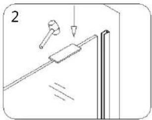
text_image
2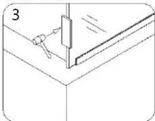
natural_image
Technical line drawing of a mechanical assembly with a bracket and tool (no text or symbols)Fig. 19

natural_image
Isometric line drawing of a modular room with two doors and a central shelf (no text or symbols)Fig. 20
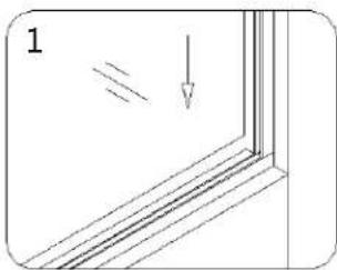
- Place the U-Channel 2 (bottom profile) (29) for the Stationary glass (11) onto the ledge in line with the inside mark and flush with 45° corner cut.
Mark the drill holes on the ledge through the predrilled holes in the U-Channel 2 and drill the holes using ∅5/16" drill bit.
Insert the ∅5/16" Wall anchors (13).
Apply waterproof silicone along the bottom surface and around the holes of the U-Channel 2 and fasten it to the ledge with the Countersunk screws ST4.2×40 (23).
NOTE: The surface needs to be clean and free of debris before applying silicone.
See Fig. 21 & 22 for details.

text_image
inside outside 1
natural_image
Pure technical line drawing of a corner joint detail (no text or symbols)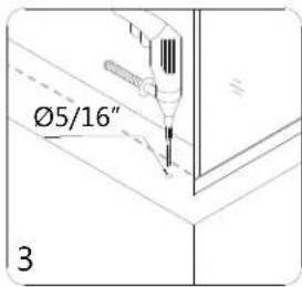
text_image
Ø5/16" 3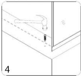
natural_image
Technical line drawing of a mechanical assembly with no visible text or symbols
text_image
waterproof silicone 5
natural_image
Technical line drawing of a mechanical assembly with a screw and base mount (no text or symbols)Fig. 21

natural_image
Isometric line drawing of a room with two doors and a wall-mounted cabinet (no text or symbols)Fig. 22
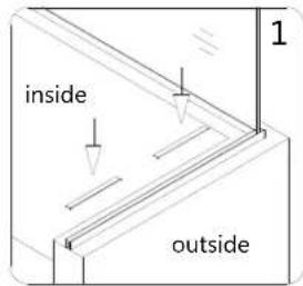
- Insert the provided Adjustment Spacers (28) into U-Channel 2 (bottom profile) (29) for minor adjustments if necessary. Apply Waterproof silicone into the groove of the U-Channel 2 (bottom profile) (29) and sparingly along the exposed vertical edge of the Return panel glass (26).
See Fig. 23 & 24 for details.
text_image
inside outside 1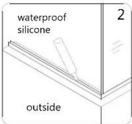
text_image
waterproof silicone outside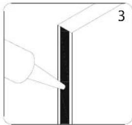
natural_image
Simple line drawing of a vertical panel with a hand pointing to it, labeled '3' (no text or symbols on the diagram itself)Fig. 23

natural_image
Isometric line drawing of a cabinet with open door and side panel, showing internal components and a small inset view (no text or symbols)Fig. 24
- Slide the Stationary glass (11) into the groove of the U-Channel. Make sure the vertical edge of the Stationary glass is flush with outer face of the Return panel glass (26) at the corner.
Apply a bead of silicone on the open end of the U-Channel, and its connection.
Ensure that the silicone applied to the open end is flat and smooth so that it will not interfere with the installation of the L-shaped strip*(08) in step #20.
natural_image
Pure technical diagram showing a mechanical component with an arrow indicating direction (no text or symbols)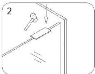
natural_image
Simple line drawing of a door with a hammer and lever, no text or symbols present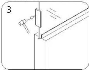
natural_image
Technical line drawing of a mechanical assembly with a bracket and clamping tool (no text or symbols)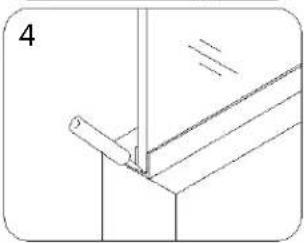
natural_image
Technical line drawing of a mechanical joint or bracket assembly (no text or symbols)Fig. 25
NOTE:
If you have difficulty sliding the Stationary glass into the U-Channel, you can slightly tap on the Stationary glass with a rubber mallet and a piece of wood.
See fig. 25 & 26 for details.
natural_image
Isometric line drawing of a cabinet with open door and side panels (no text or symbols)Fig. 26
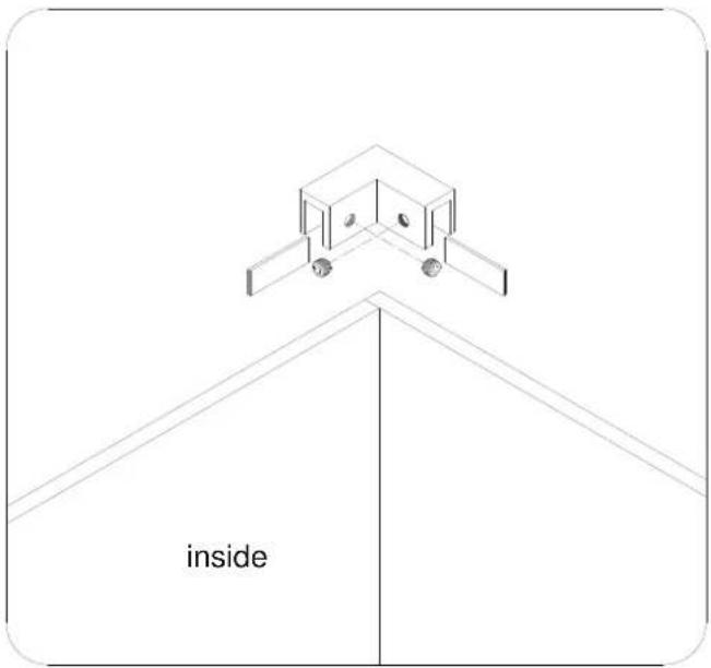
- Attach the 90° Corner Bracket (30) to the top corner of both glass panels. Ensure that the 90° Corner Bracket is square and gaskets are aligned properly before tightening the glass holding screws.
Temporarily secure the bottom corner of the glass panels with a generous strip of Painter's tape to keep the corner tight until the silicone cures.
See fig. 27 & 28 for details.
text_image
insideFig. 27

natural_image
Isometric line drawing of a modular cabinet or enclosure structure with no text or symbolsFig. 28
- Apply waterproof silicone along the connection of all U-Channels to the wall and ledge on the inside of shower. Carefully apply an even bead of silicone down the inside corner of the glass panels.
Allow 24 hours for the silicone to fully cure before using the shower.
See Fig. 29 & 30 for details.

text_image
waterproof silicone insideFig. 29

text_image
waterproof silicone insideFig. 30
ATTENTION:
Prior to this step, please be sure the part of the wall and glass edge for installation of the L-shaped strip*(08) is clean, dry and free from soap, oil and any construction debris.
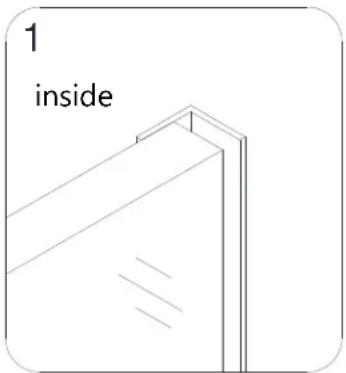
- Align the L-shaped strip*(08) on the vertical edge of the Stationary glass (11) so that the door glass rests flush against it in the closed position. Ensure that the bottom of the L-Shaped strip makes contact with the threshold rather than aligning the top of the strip to the top of the Stationary glass.
Note the position on the wall then gently remove the plastic tape from the adhesive side of the L-shaped strip. Firmly press it onto the vertical edge of the Stationary glass and to the surface of the half wall.
See Fig. 31 for details.
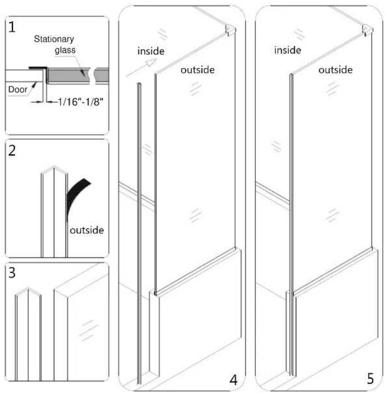
Fig. 31
Product Maintenance
BASES and BACKWALLS: To ensure long lasting life for your acrylic back walls: wipe them off after each use with a soft cloth. To clean the acrylic back walls use non-abrasive sprays or cream based cleaners. Avoid the use of aerosol spray cleaners. Never use abrasive cleansers, metal brushes or scrapers that could scratch or dull the surface.
GLASS: To ensure long lasting life for your glass shower products: wipe them off after each use with a soft cloth. Rinse and wipe off the glass using either a soft cloth or a squeegee to prevent soap buildup and water spots (Hard water can etch the surface of the glass over time if left to dry). To prevent scratching the surface: never use abrasive cleaners or cleaning products that contain scouring agents. Never use bristle brushes or abrasive sponges that may scratch the surface.
HARDWARE: To ensure a long lasting finish: wipe off the metal parts after each use with a soft cloth. Do not use abrasive cleaners or cleaning products containing ammonia, bleach or acid. If accidentally used, rinse the surface as soon as possible to prevent damage to the finish (peeling or corrosion). After cleaning the polished finishes, rinse thoroughly and wipe dry with soft cloth. Clean stainless steel surfaces at least once a week. When applying stainless steel cleaner or polish to stainless steel hardware, work with (not across) the grain. Never use an abrasive sponge or cloth, steel wool or wired brush as these may permanently scratch the surfaces.
DREAMLINE® dream in style
TEL: 866-731-2244
FAX: 866-857-3638
DREAMLINE.COM
For more information on DreamLine® Shower Doors and Enclosures please visit DreamLine.com