99-8722B - Kit voiture Metra - Free user manual and instructions
Find the device manual for free 99-8722B Metra in PDF.

User questions about 99-8722B Metra
0 question about this device. Answer the ones you know or ask your own.
Ask a new question about this device
Download the instructions for your Kit voiture in PDF format for free! Find your manual 99-8722B - Metra and take your electronic device back in hand. On this page are published all the documents necessary for the use of your device. 99-8722B by Metra.
USER MANUAL 99-8722B Metra
INSTALLATION INSTRUCTIONS FOR PART 99-8722B
APPLICATIONS
Mercedes-Benz:
C-Class 2001-2004
CLK55 AMG and CLK500 2003-2004, CLK 2004
G-Class 2002-2006
99-8722B
KIT FEATURES
• ISO DIN radio provision with pocket
- Painted matte black

natural_image
Interior view of a car dashboard with air vent and control panel (no visible text or symbols)KIT COMPONENTS
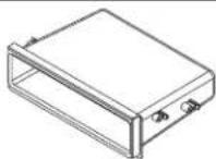
• A) Radio Housing Trim Panel • B) Brackets • C) Pocket • D) (8) #8 x 3/8" Phillips Screws
A
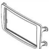
BCD


WIRING & ANTENNA CONNECTIONS (sold separately)
Wiring Harness: • 70-9401
Antenna Adapter: • 40-VW12
Table of Contents
Dash Disassembly
— Mercedes-Benz C-Class 2001-2004 .... 2
— Mercedes-Benz CLK55 AMG, CLK500 2003-2004
Mercedes-Benz CLK 2004....3
— Mercedes-Benz G-Class 2002-2006....3
Kit Assembly
- ISO DIN radio provision....4
TOOLS REQUIRED
- Panel removal tool
- Phillips screwdriver
- Socket Wrench • Torx driver
CAUTION: Metra recommends disconnecting the negative battery terminal before beginning any installation. All accessories, switches, and especially air bag indicator lights must be plugged in before reconnecting the battery or cycling the ignition.
NOTE: Refer to the instructions included with the aftermarket radio.

99-8722B
Dash Disassembly
Mercedes-Benz C-Class
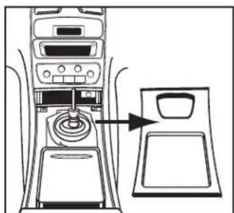
- Unclip but do not remove shifter trim (small piece with gear indicators and chrome trim).
- Unclip the center console trim panel and twist around the smaller shifter trim to remove. (Figure A)
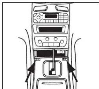
- Remove the ashtray insert by releasing (2) plastic clips on the bottom lip of the ashtray assembly. (Figure B)
- Inside each vent, using a small flat screwdriver push the lower tab inward toward the center of the vent and then rotate each vent up to expose (1) Torx head screw. Loosen the Torx screws (It is not necessary to remove the screws.) Push the upper clip inward and rotate the vent downward to expose (1) spring clip in the top of the vent assembly. (Figure C)

natural_image
Diagram of a car interior showing dashboard, intake manifold, and backseat with an arrow pointing to the intake manifold (no text or symbols present)(Figure A)
natural_image
Top-down line drawing of a car dashboard with air vent, control panel, and directional arrows indicating movement (no text or symbols)(Figure B)
-
Unclip the (2) metal clips at the bottom edge of the climate control/radio trim panel and remove trim panel.
-
Push down on the spring clips to remove the vent assembly. Remove (4) Phillips screws securing factory radio then unplug and remove the radio.
Continue to kit assembly on back

text_image
Diagram showing four different car interior compartments with directional arrows indicating movement or flow, likely illustrating vehicle or airflow dynamics.(Figure C)

99-8722B
Dash Disassembly
Mercedes-Benz CLK55 AMG, CLK500, CLK
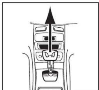
- Loosen shifter boot and pull up over shifter handle. (Figure A)
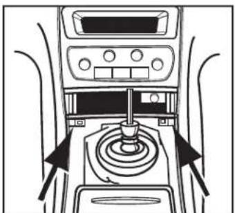
- Turn the retainer on the shifter 1/2 turn to remove shifter handle and boot. (Figure B)
- Unclip and remove the shifter trim panel. (Figure C)
- Remove the ashtray insert by releasing (2) plastic clips on the bottom lip of the ashtray assembly. (Figure D)
- Remove (2) screws from bottom of climate control/radio trim panel.
- Unclip climate control/radio trim panel. Unplug and remove trim panel.
- Remove the (4) screws securing the radio then unplug and remove the radio.
Continue to kit assembly on back
natural_image
Diagram of a vehicle interior with an upward arrow indicating direction (no text or symbols)(Figure A)

natural_image
Line drawing of a car interior showing the dashboard and seat area with an arrow pointing to the door (no text or symbols present)(Figure C)

natural_image
Line drawing of a car interior showing a hand inserting a cup into a sink (no text or symbols)(Figure B)
natural_image
Diagram of a car interior showing a gear shift mechanism with arrows indicating direction (no text or labels)(Figure D)
Mercedes-Benz G-Class
- Remove two Phillips screws from inside ashtray assembly.
- Remove the traction control switch plate and remove one Phillips screw inside.
- Unsnap and remove radio panel.
- Remove radio.
Continue to kit assembly on back

INSTALLATION INSTRUCTIONS FOR PART 99-8722B

Kit Assembly
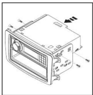
ISO DIN radio provision
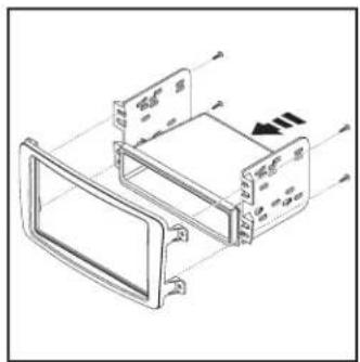
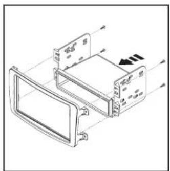
- Mount the pocket to the radio brackets with the (4) #8 x 3/8" Phillips screws supplied. (Figure A)
- Mount the bracket/pocket assembly to the radio housing trim panel with the included #8 screws. (Figure B)
- Slide the radio into radio brackets and secure with screws supplied with the unit. (Figure C)
- Locate the factory wiring harness and antenna plug in the dash. Metra recommends using the proper mating adapters from Metra and/or AXXESS.
- Mount the new radio assembly into the dash and reassemble dash in reverse order of disassembly.

natural_image
Technical line drawing of a mechanical housing or enclosure with mounting holes and internal components (no text or symbols)(Figure A) (Figure B) (Figure C)
natural_image
Technical line drawing of a mechanical device housing with mounting brackets and a central panel (no text or symbols)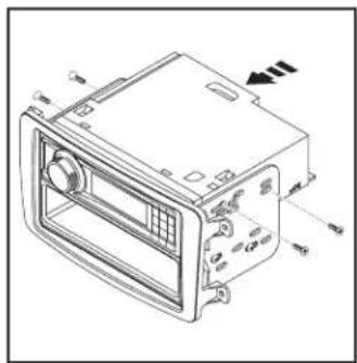
natural_image
Technical line drawing of a car air conditioner unit with labeled ports and airflow direction (no text or symbols)
Metra recommends MECP certified technicians

KNOWLEDGE IS POWER
Enhance your installation and fabrication skills by enrolling in the most recognized and respected mobile electronics school in our industry.
Log onto www.installerinstitute.com or call 800-354-6782 for more information and take steps toward a better tomorrow.
natural_image
Interior view of a car dashboard with air vent and control panel (no visible text or symbols)COMPONENTES DEL KIT
natural_image
Diagram of a car air intake system with control panel and fan (no text or labels)(Figura A)

natural_image
Top-down line drawing of a car dashboard with air intake and control panel (no text or symbols)(Figura B)
text_image
Diagram showing four different airflow or ventilation system configurations with arrows indicating direction of movement.(Figura C)

99-8722B
Ensamble del kit
Mercedes-Benz CLK55 AMG, CLK500, CLK
natural_image
Diagram of a vehicle air intake system with no text or labels(Figura A)
natural_image
Diagram of a car air intake system showing fan, pump, and door (no text or labels)(Figura C)

natural_image
Line drawing of a car interior showing a hand operating the seat with a black arrow pointing to the handle (no text or symbols)(Figura B)

natural_image
Interior view of a car dashboard with control panel and directional arrows indicating motion (no text or symbols)(Figura D)
Mercedes-Benz G-Class
natural_image
Technical line drawing of a rectangular electronic device with mounting holes and internal components (no text or symbols)(Figura A) (Figura B) (Figura C)
natural_image
Technical line drawing of a mechanical component with mounting brackets and directional arrows (no text or symbols)