EKI-2741LXI-BE - Unknown Advantech - Free user manual and instructions
Find the device manual for free EKI-2741LXI-BE Advantech in PDF.

User questions about EKI-2741LXI-BE Advantech
0 question about this device. Answer the ones you know or ask your own.
Ask a new question about this device
Download the instructions for your Unknown in PDF format for free! Find your manual EKI-2741LXI-BE - Advantech and take your electronic device back in hand. On this page are published all the documents necessary for the use of your device. EKI-2741LXI-BE by Advantech.
USER MANUAL EKI-2741LXI-BE Advantech
natural_image
Illustration of three server racks with circuit breakers and connectors, no text or symbols presentEKI-2741FI/LXI/SXI
10/100/1000T (X) to Fiber Optic Gigabit Industrial Media Converters
Copyright
The documentation and the software included with this product are copyrighted 2017 by Advantech Co., Ltd. All rights are reserved. Advantech Co., Ltd. reserves the right to make improvements in the products described in this manual at any time without notice. No part of this manual may be reproduced, copied, translated or transmitted in any form or by any means without the prior written permission of Advantech Co., Ltd. Information provided in this manual is intended to be accurate and reliable. However, Advantech Co., Ltd. assumes no responsibility for its use, nor for any infringements of the rights of third parties, which may result from its use.
Acknowledgements
Intel and Pentium are trademarks of Intel Corporation.
Microsoft Windows and MS-DOS are registered trademarks of Microsoft Corp.
All other product names or trademarks are properties of their respective owners.
Product Warranty (5 years)
Advantech warrants to you, the original purchaser, that each of its products will be free from defects in materials and workmanship for five years from the date of purchase.
This warranty does not apply to any products which have been repaired or altered by persons other than repair personnel authorized by Advantech, or which have been subject to misuse, abuse, accident or improper installation. Advantech assumes no liability under the terms of this warranty as a consequence of such events.
Because of Advantech's high quality-control standards and rigorous testing, most of our customers never need to use our repair service. If an Advantech product is defective, it will be repaired or replaced at no charge during the warranty period. For out-of-warranty repairs, you will be billed according to the cost of replacement materials, service time and freight. Please consult your dealer for more details.
If you think you have a defective product, follow these steps:
-
Collect all the information about the problem encountered. (For example, CPU speed, Advantech products used, other hardware and software used, etc.) Note anything abnormal and list any on screen messages you get when the problem occurs.
-
Call your dealer and describe the problem. Please have your manual, product, and any helpful information readily available.
-
If your product is diagnosed as defective, obtain an RMA (return merchandize authorization) number from your dealer. This allows us to process your return more quickly.
-
Carefully pack the defective product, a fully-completed Repair and Replacement Order Card and a photocopy proof of purchase date (such as your sales receipt) in a shippable container. A product returned without proof of the purchase date is not eligible for warranty service.
-
Write the RMA number visibly on the outside of the package and ship it prepaid to your dealer.
Part No. Edition 1
Printed in Taiwan April 2017
Declaration of Conformity
CE
This product has passed the CE test for environmental specifications when shielded cables are used for external wiring. We recommend the use of shielded cables. This kind of cable is available from Advantech. Please contact your local supplier for ordering information.
This product has passed the CE test for environmental specifications. Test conditions for passing included the equipment being operated within an industrial enclosure. In order to protect the product from being damaged by ESD (Electrostatic Discharge) and EMI leakage, we strongly recommend the use of CE-compliant industrial enclosure products.
FCC Class A
Note: This equipment has been tested and found to comply with the limits for a Class A digital device, pursuant to part 15 of the FCC Rules. These limits are designed to provide reasonable protection against harmful interference when the equipment is operated in a commercial environment. This equipment generates, uses, and can radiate radio frequency energy and, if not installed and used in accordance with the instruction manual, may cause harmful interference to radio communications. Operation of this equipment in a residential area is likely to cause harmful interference in which case the user will be required to correct the interference at his own expense.
Technical Support and Assistance
- Visit the Advantech web site at www.advantech.com/support where you can find the latest information about the product.
- Contact your distributor, sales representative, or Advantech's customer service center for technical support if you need additional assistance. Please have the following information ready before you call:
– Product name and serial number
– Description of your peripheral attachments
– Description of your software (operating system, version, application software, etc.)
– A complete description of the problem - The exact wording of any error messages
Warnings, Cautions and Notes
Warning! Warnings indicate conditions, which if not observed, can cause personal injury!

Caution! Cautions are included to help you avoid damaging hardware or losing data. e.g.

There is a danger of a new battery exploding if it is incorrectly installed. Do not attempt to recharge, force open, or heat the battery. Replace the battery only with the same or equivalent type recommended by the manufacturer. Discard used batteries according to the manufacturer's instructions.
Note! Notes provide optional additional information.

Document Feedback
To assist us in making improvements to this manual, we would welcome comments and constructive criticism. Please send all such - in writing to: ICG.Support@advantech.com.tw
Packing List
Before setting up the system, check that the items listed below are included and in good condition. If any item does not accord with the table, please contact your dealer immediately.
■ 1 x EKI-2741FI/LXI/SXI Industrial Ethernet Switch
■ 2 x Wall Mounting Bracket and Screws
■ 1 x DIN-rail Mounting Bracket and Screws
■ 1 x EKI-2741FI/LXI/SXI Startup Manual
Safety Instructions
- Read these safety instructions carefully.
- Keep this User Manual for later reference.
- Disconnect this equipment from any Power outlet before cleaning. Use a damp cloth. Do not use liquid or spray detergents for cleaning.
- For plug-in equipment, the power outlet socket must be located near the equipment and must be easily accessible.
- Keep this equipment away from humidity.
- Put this equipment on a reliable surface during installation. Dropping it or letting it fall may cause damage.
- The openings on the enclosure are for air convection. Protect the equipment from overheating. DO NOT COVER THE OPENINGS.
- Make sure the voltage of the power source is correct before connecting the equipment to the power outlet.
- Position the power cord so that people cannot step on it. Do not place anything over the power cord.
- All cautions and warnings on the equipment should be noted.
- If the equipment is not used for a long time, disconnect it from the power source to avoid damage by transient overvoltage.
- Never pour any liquid into an opening. This may cause fire or electrical shock.
- Never open the equipment. For safety reasons, the equipment should be opened only by qualified service personnel.
- If one of the following situations arises, get the equipment checked by service personnel:
- The power cord or plug is damaged.
- Liquid has penetrated into the equipment.
- The equipment has been exposed to moisture.
- The equipment does not work well, or you cannot get it to work according to the user's manual.
- The equipment has been dropped and damaged.
- The equipment has obvious signs of breakage.
- DO NOT LEAVE THIS EQUIPMENT IN AN ENVIRONMENT WHERE THE STORAGE TEMPERATURE MAY GO BELOW -20^ C ( -4^ F) OR ABOVE 60^ C ( 140^ F). THIS COULD DAMAGE THE EQUIPMENT. THE EQUIPMENT SHOULD BE IN A CONTROLLED ENVIRONMENT.
- CAUTION: DANGER OF EXPLOSION IF BATTERY IS INCORRECTLY REPLACED. REPLACE ONLY WITH THE SAME OR EQUIVALENT TYPE RECOMMENDED BY THE MANUFACTURER, DISCARD USED BATTERIES ACCORDING TO THE MANUFACTURER'S INSTRUCTIONS.
Safety Precaution - Static Electricity
Follow these simple precautions to protect yourself from harm and the products from damage.
To avoid electrical shock, always disconnect the power from your PC chassis before you work on it. Don't touch any components on the CPU card or other cards while the PC is on.
- Disconnect power before making any configuration changes. The sudden rush of power as you connect a jumper or install a card may damage sensitive electronic components.
Technical Support and Assistance
- Visit the Advantech web site at www.advantech.com/support where you can find the latest information about the product.
- Contact your distributor, sales representative, or Advantech's customer service center for technical support if you need additional assistance. Please have the following information ready before you call:
– Product name and serial number
– Description of your peripheral attachment
– Description of your software (operating system, version, application software, etc.)
– A complete description of the problem
- The exact wording of any error messages
Regional Service & Customization Centers
| China | Taiwan | Netherlands | Poland | USA/ Canada |
| Kunshan | Taipei | Eindhoven | Warsaw | Milpitas, CA |
| 86-512-5777-5666 | 886-2-2792-7818 | 31-40-267-7000 | 48-22-33-23-740 / 41 | 1-408-519-3898 |
Worldwide Offices
| Greater China | Asia Pacific | Europe | Americas | ||||
| China | Japan | Toll Free | 00800-2426-8080 | North America | |||
| Toll Free | 800-810-0345 | Toll Free | 0800-500-1055 | Germany | Toll Free | 1-888-576-9668 | |
| Beijing | 86-10-6298-4346 | Tokyo | 81-3-6802-1021 | Munich | 49-89-12699-0 | Cincinnati | 1-513-742-8895 |
| Shanghai | 86-21-3632-1616 | Osaka | 81-6-6267-1887 | Hilden / D’dorf | 49-2103-97-885-0 | Milpitas | 1-408-519-3898 |
| Shenzhen | 86-755-8212-4222 | Irvine | 1-949-420-2500 | ||||
| Chengdu | 86-28-8545-0198 | France | |||||
| Hong Kong | 852-2720-5118 | Korea | Paris | 33-1-4119-4666 | Brazil | ||
| Toll Free | 080-363-9494 | Toll Free | 0800-770-5355 | ||||
| Seoul | 82-2-3663-9494 | Saude-São Paulo | 55-11-5592-5355 | ||||
| Taiwan | Singapore | Italy | |||||
| Toll Free | 0800-777-111 | Singapore | 65-6442-1000 | Milano | 39-02-9544-961 | Mexico | |
| Neihu | 886-2-2792-7818 | Toll Free | 1-800-467-2415 | ||||
| Xindian | 886-2-2218-4567 | Mexico City | 52-55-6275-2777 | ||||
| Taichung | 886-4-2378-6250 | Malaysia | Benelux & Nordics | ||||
| Kaohsiung | 886-7-229-3600 | Toll Free | 1800-88-1809 | Breda | 31-76-5233-100 | ||
| Kuala Lumpur | 60-3-7725-4188 | UK | |||||
| Penang | 60-4-537-9188 | Reading | 44-0118-929-4540 | ||||
| Indonesia | Poland | ||||||
| Jakarta | 62-21-769-0525 | Warsaw | 48-22-33-23-740 / 41 | ||||
| Thailand | Russia | ||||||
| Bangkok | 66-2-248-3140 | Toll Free | 8-800-550-01-50 | ||||
| Moscow | 7-495-232-1692 | ||||||
| India | |||||||
| Toll Free | 1-800-425-5070 | ||||||
| Pune | 91-20-39482075 | ||||||
| Bangalore | 91-80-2545-0206 | ||||||
| Australia | 1300-308-531 | ||||||
| Toll Free | 61-3-9797-0100 | ||||||
| Melbourne | 61-2-9476-9300 | ||||||
| Sydney | |||||||
About This Manual
This user manual is intended to guide professional installers in installing and configuring the Serial Device Server. It includes technical specifications, software utility introduction, as well as procedures for the use of the software utility to self-manage the devices.
Contents
Chapter 1 Overview......1
1.1 Introduction 2
1.2 Device Features ...... 2
1.3 Device Specifications .... 3
Chapter 2 Getting Started....5
2.1 Hardware Overview....6
2.1.1 Front View....6
2.1.2 Rear View 8
2.1.3 Top View 8
2.1.4 LED Indicators 9
2.1.5 Dimensions 9
2.2 Connecting Hardware 11
2.2.1 Choosing a Location 11
2.2.2 DIP Switch 15
2.2.3 SFP Connection.... 15
2.2.4 Ethernet Connection 18
2.2.5 Fiber Connection.... 18
2.2.6 Power Connection.... 20
Chapter 3 Troubleshooting ......21
3.1 Troubleshooting 22
List of Figures
Figure 2.1 Front View 6
Figure 2.2 Front View 7
Figure 2.3 Rear View 8
Figure 2.4 Top View....8
Figure 2.5 Dimensions....9
Figure 2.6 Dimensions....10
Figure 2.7 Installing the DIN-Rail Mounting Kit....11
Figure 2.8 Removing the DIN-Rail....12
Figure 2.9 Installing Wall Mount Plates 13
Figure 2.10 Wall Mounting Screw Dimensions....14
Figure 2.11 Wall Mount Installation .... 14
Figure 2.12 DIP Switch....15
Figure 2.13 Installing an SFP Transceiver.... 16
Figure 2.14 Attaching a Fiber Optic Cable to a Transceiver....16
Figure 2.15 Removing a Fiber Optic Cable to a Transceiver....17
Figure 2.16 Removing an SFP Transceiver....17
Figure 2.17 Ethernet Plug & Connector Pin Position....18
Figure 2.18 Pin Assignment of the SC Connector....19
Figure 2.19 Power Wiring for EKI-2741FI/LXI/SXI....20
Chapter 1
Overview
1.1 Introduction
The EKI-2741FI/LXI/SXI are designed to convert Gigabit Ethernet networks to Gigabit fiber networks by transparently converting Ethernet signals to optic signals. Therefore, the EKI-2741FI/LXI/SXI are ideal solutions for Fiber To The Building (FTTB) applications at central offices or local sites. EKI-2741FI/LXI/SXI support MDI/MDIX auto detection, so you don't need to use crossover wires. Furthermore, the EKI-2741FI/LXI/SXI accept a wide voltage range from 12 \~ 48 V _DC .
EKI-2741FI/LXI/SXI are an enhanced gigabit Ethernet to fiber optic converter. Aside from its standard features, the versatile the EKI-2741FI/LXI/SXI also have the LFP (Link Fault Pass-through) feature, which allows the transmission of packets even when one link fails. EKI-2741FI/LXI/SXI forces the shutdown of the failed link to allow for an application continuous transmission.
1.2 Device Features
■ Provides 1 x 10/100/1000 Mbps Ethernet port with RJ45 connector
■ Provides 1 x 1000 Mbps fiber port with SC type connector for 1000Base-SX/LX device
■ Provides 1 x 100/1000 Mbps Ethernet port with SFP (mini-GBIC) type
■ Provides DIP switch for power alarm & LFP
■ Supports MDI/MDI-X auto crossover
■ Supports auto-negotiation
■ Supports redundant 12 \~ 48 V _DC power input
■ Provides flexible mounting: DIN-rail and wall mounting
■ Provides Link Fault Pass-through (LFP)
■ Jumbo Frame: 9216 bytes
1.3 Device Specifications
| Specifications Description | ||
| Interface I/O Ports | ■ 1 x RJ45■ 1 x SFP type fiber connector (EKI-2741F)■ 1 x SC type fiber connector (EKI-2741SX/LX)See the Ethernet Communications and Fiber Communications | |
| Power Connector 6-pin removable screw terminal (power & relay) | ||
| Physical Enclosure IP30, metal shell with solid mounting kits | ||
| LED Display System LED P1, P2, P-Fail | ||
| Environment Operating Temperature | ■ -40 ~ 75°C (-40 ~ 167°F) | |
| Ethernet Communications | Compatibility | IEEE 802.3, 802.3u, 802.3ab, 802.3x, IEEE 802.3z |
| Speed | 10/100/1000 Mbps, auto MDI/MDIX | |
| Port Connector 8-pin RJ45 | ||
| Ports | 1 x RJ45 | |
| Protection | Built-in 1.5 KV magnetic isolation | |
| Fiber Communications | Multi-mode (EKI-2741SX/SXI) | ■ Wavelength: 850 nm■ Tx Power: -4/-9.5 dBm■ Rx Sensitivity: -18 dBm■ Parameters: 50/125 um, 62.5/125 um |
| Single-mode (EKI-2741LX/LXI) | ■ Wavelength: 1310 nm■ Tx Power: -3/-9.5 dBm■ Rx Sensitivity: -20 dBm■ Parameters: 9/125 um | |
| Power Consumption | Power Consumption | 3.5W |
| Power Input | 12 ~ 48 VDC | |
Specifications Description
| Regulatory Approvals | Safety UL 60950 | |
| EMI FCC Part 15 Subpart B Class A, EN 55022 Class A | ||
| EMS | EN 61000-4-2 | |
| EN 61000-4-3 | ||
| EN 61000-4-4 | ||
| EN 61000-4-5 | ||
| EN 61000-4-6 | ||
| EN 61000-4-8 | ||
| Shock IEC 60068-2-27 | ||
| Freefall IEC 60068-2-32 | ||
| Vibration IEC 60068-2-6 | ||
Chapter 2
Getting Started
2.1 Hardware Overview
2.1.1 Front View
The following view applies to EKI-2741FI.

text_image
P1 P2 P-Fail LNK /ACT 1 2 3 4 5 1000M LNK /ACT 6 EKI-2741FIFigure 2.1 Front View
No. Item Description
| 1 System LED panel See “LED Indicators” on page 9 for further details. |
| 2 LNK/ACT LED Link activity LED. |
| 3 ETH port 100/1000BASE-X (SFP) port. |
| 4 DIP switch Confige operation mode for LFP (Link Fault Pass-through). |
| 5 1000M, LNK/ACT 1000M LED and link activity LED.LED |
| 6 ETH port 10/100/1000Base-T/TX ports x 1. |
The following view applies to EKI-2741LXI and EKI-2741SXI.
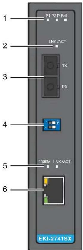
text_image
1 P1 P2 P-Fail 2 LNK /ACT 3 TX RX 4 1000M LNK /ACT 5 6 EKI-2741SXFigure 2.2 Front View
No. Item Description
1 System LED panel See "LED Indicators" on page 9 for further details.
2 LNK/ACT LED Link activity LED.
3 Fiber port 1000 Mbps fiber port with SC type connector.
4 DIP switch Confige operation mode for LFP (Link Fault Pass-through).
5 1000M, LNK/ACT LED 1000M LED and link activity LED.
6 ETH port 10/100/1000Base-T/TX ports x 1.
2.1.2 Rear View

natural_image
Diagram of a vertical panel with labeled components and a numbered marker (1), showing internal features without any readable text or symbols.Figure 2.3 Rear View
No. Item Description
1 DIN-Rail mounting plate
Mounting plate used for the installation to a standard DIN rail
2.1.3 Top View

text_image
PWR2 1A@24V PWR1 DC12 -48V V2- V2+ V1L P-Fall 1 2Figure 2.4 Top View
No. Item Description
1 Terminal block Connect cabling for power and alarm wiring
2 Ground terminal Screw terminal used to ground chassis
2.1.4 LED Indicators
| No. LED Name LED Color Description | |
| 1 P1 Green on Power input 1 is active. | |
| Off Power input 1 is inactive. | |
| 2 P2 Green on Power input 2 is active. | |
| Off Power input 2 is inactive. | |
| 3 P-Fail Red on Power input 1 or 2 has failed. | |
| Off Power input 1 and 2 are both functional, or no power input. | |
| 4 LINK/ACT (fiber) Green on Connected to network. | |
| Blinking Network is active. | |
| Off Not connected to network. | |
| 5 1000M (RJ45) Yellow on Link to 1000M bps network. | |
| Off Not connected to network. | |
| 6 LINK/ACT (RJ45) Green on Connected to network. | |
| Blinking Network is active. | |
| Off Not connected to network. | |
2.1.5 Dimensions
The following view applies to EKI-2741FI.
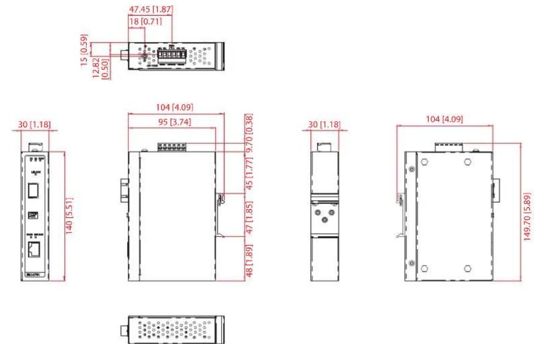
Figure 2.5 Dimensions
The following view applies to EKI-2741LXI and EKI-2741SXI.

text_image
15 [0.59] 12.82 [0.50] 47.45 [1.87] 18 [0.71]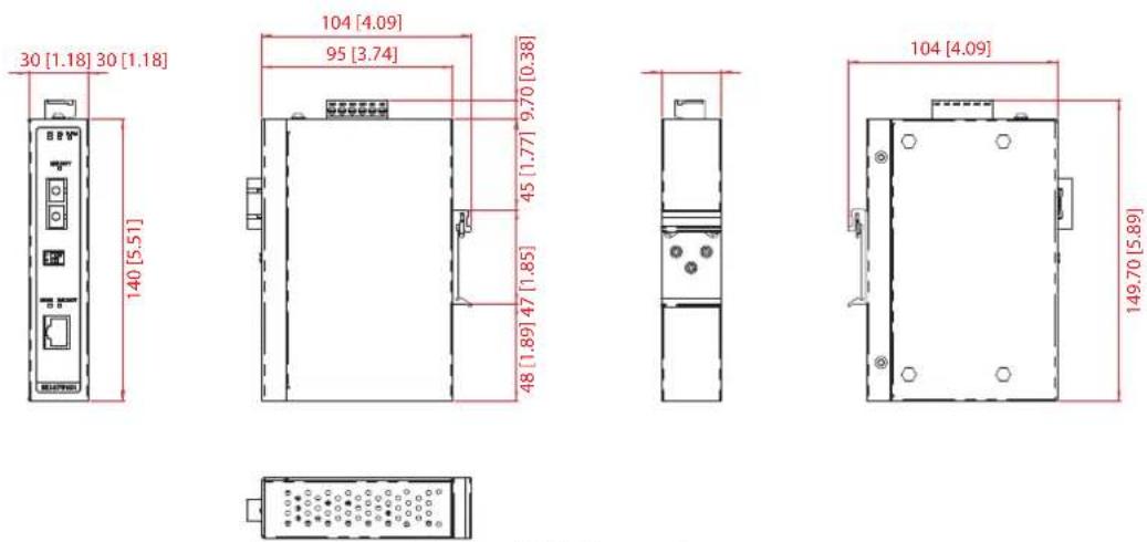
Figure 2.6 Dimensions
2.2 Connecting Hardware
2.2.1 Choosing a Location
2.2.1.1 DIN Rail Mounting
The DIN rail mount option is the quickest installation option. Additionally, it optimizes the use of rail space.
The metal DIN rail kit is secured to the rear of the device. The device can be mounted onto a standard 35mm (1.37") x 75 mm (3") height DIN rail. The devices can be mounted vertically or horizontally. Refer to the following guidelines for further information.
Note! A corrosion-free mounting rail is advisable.

When installing, make sure to allow for enough space to properly install the cabling.
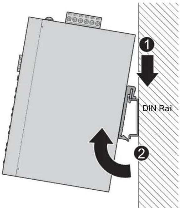
Installing the DIN-Rail Mounting Kit
- Insert the top back of the mounting bracket over the DIN rail.
- Push the bottom of the device towards the DIN rail until it snaps into place.
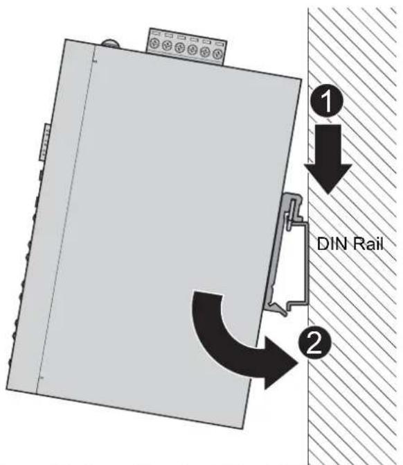
text_image
① ↓ DIN Rail ②Figure 2.7 Installing the DIN-Rail Mounting Kit
Removing the DIN-Rail Mounting Kit
- Push the device down to free the bottom of the plate from the DIN rail.
- Rotate the bottom of the device towards you and away from the DIN rail.
- Once the bottom is clear of the DIN rail, lift the device straight up to unhook it from the DIN rail.
text_image
1 ↓ DIN Rail 2Figure 2.8 Removing the DIN-Rail
2.2.1.2 Wall-Mounting
The wall mounting option provides better shock and vibration resistance than the DIN rail vertical mount.
Note! When installing, make sure to allow for enough space to properly install the cabling.

Before the device can be mounted on a wall, you will need to remove the DIN rail plate.
- Rotate the device to the rear side and locate the DIN mounting plate.
- Remove the screws securing the DIN mounting plate to the rear panel of the server.
- Remove the DIN mounting plate. Store the DIN mounting plate and provided screws for later use.
- Align the wall mounting plates on the rear side. The screw holes on the device and the mounting plates must be aligned, see the following illustration.
- Secure the wall mount plates with M3 screws, see the following figure.
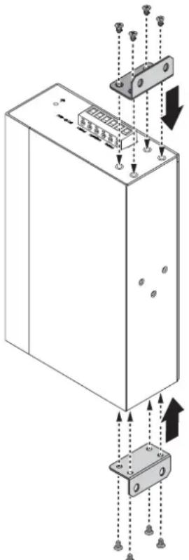
natural_image
Technical diagram of an electrical enclosure with mounting hardware and wiring connections (no text or symbols)Figure 2.9 Installing Wall Mount Plates
Once the wall mounting plates are secure on the device, you will need to attach the wall screws (x8).
- Locate the installation site and place the server against the wall, making sure it is the final installation location.
- Use the wall mount plates as a guide to mark the locations of the screw holes.
- Drill four holes over the four marked locations on the wall, keeping in mind that the holes must accommodate wall sinks in addition to the screws.
-
Insert the wall sinks into the walls.
-
To mount the wall plate, use screws of the size shown in the following illustration.

text_image
8.0 mm 4.0 mmFigure 2.10 Wall Mounting Screw Dimensions
Note!
■ Make sure the screws dimensions are suitable for use with the wall mounting plate.
Do not completely tighten the screws into the wall. A final adjustment may be needed before fully securing the wall mounting plates on the wall.
- Align the wall mount plate over the screws on the wall.
- Install the wall mount plate on the screws and slide it forward to lock in place, see the following figure.

text_image
Diagram showing a mechanical or electrical component with labeled parts and directional arrow, likely illustrating a process or assembly.Figure 2.11 Wall Mount Installation
- Once the device is installed on the wall, tighten the screws to secure the device.
2.2.2 DIP Switch
The DIP switch is used to configure operation mode for LFP (Link Fault Pass-Through) and operation mode for UTP/Fiber port. The default value of DIP switch is OFF.

Figure 2.12 DIP Switch
S/W No Status Description
1 ON Enables Power Alarm.
OFF Disable Power Alarm.
2 ON Enables LFP.
OFF Disables LFP.
Link Fault Pass-Through (DIP switch 2): When LFP is enabled, allowing UTP link failures to be reported to the fiber side and also allows Fiber link failures to be reported to the UTP side. Therefore, a link loss forwarding feature is provided in both UTP and Fiber side.
Note! When SW 2 is on, once the fiber or UTP/STP cable is disconnected, the

LNK/ACT LED off. When the cable is reconnected, the LNK/ACT LED blinks for 2 \~ 6 seconds which means the connection recovers from failure.
Note! Please don't change the DIP switch setting when UTP or fiber port is

transmitting or receiving data. It may cause some data error. Besides, if you change the DIP switch setting, please power off the converter and power on again to make the setting effective.
2.2.3 SFP Connection
EKI-2741FI has one SFP slot for connecting to the network segment with single or multi-mode fiber. You can choose appropriate mini-GBIC module to plug into the slot. Make sure the module is aligned correctly and then slide the module into the SFP slot until a click is heard. You can use proper multi-mode or single-mode fiber according to the used SFP module. With fiber optic, it transmits speed up to 1000 Mbps and you can prevent noise interference from the system and transmission distance up to 110 km, depending on the mini-GBIC module.
Also, if you insert the 100Mbps SFP transceiver into the SFP module even without a fiber connection to the remote, the connection of the accompanying copper port will link down immediately.
2.2.3.1 Installing SFP Modules
To connect the fiber transceiver and LC cable, use the following guidelines:
- Position the SFP transceiver with the handle on top, see the following figure.
- Locate the triangular marking in the slot and align it with the bottom of the transceiver.
- Insert the SFP transceiver into the slot until it clicks into place.
- Make sure the module is seated correctly before sliding the module into the slot. A click sounds when it is locked in place.
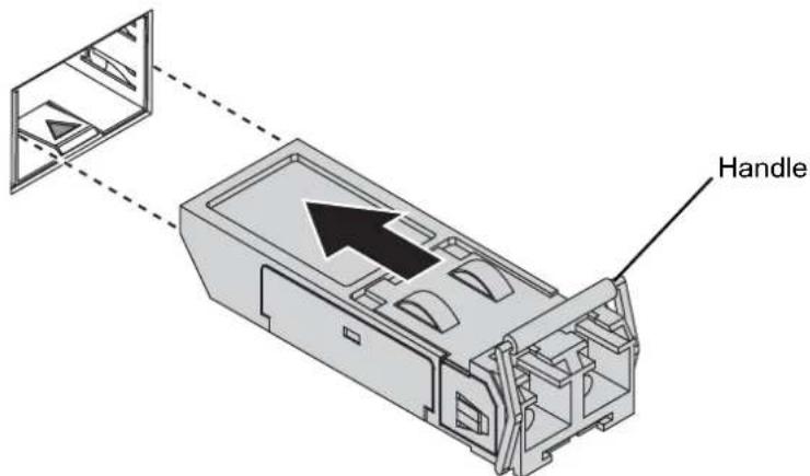
text_image
HandleFigure 2.13 Installing an SFP Transceiver
Note!If you are attaching fiber optic cables to the transceiver, continue with the following step. Otherwise, repeat the previous steps to install the remaining SFP transceivers in the device.
- Remove the protective plug from the SFP transceiver.
Note! Do not remove the dust plug from the transceiver if you are not installing the fiber optic cable at this time. The dust plug protects hardware from dust contamination.
- Insert the fiber cable into the transceiver. The connector snaps into place and locks.

natural_image
Technical illustration of a mechanical assembly with stairs and a directional arrow (no text or symbols)Figure 2.14 Attaching a Fiber Optic Cable to a Transceiver
- Repeat the previous procedures to install any additional SFP transceivers in the device.
The fiber port is now setup.
2.2.3.2 Removing SFP Modules
To disconnect an LC connector, use the following guidelines:
-
Press down and hold the locking clips on the upper side of the optic cable.
-
Pull the optic cable out to release it from the transceiver.

natural_image
Diagram of a mechanical device with directional arrows indicating flow or movement (no text or symbols present)Figure 2.15 Removing a Fiber Optic Cable to a Transceiver
- Hold the handle on the transceiver and pull the transceiver out of the slot.
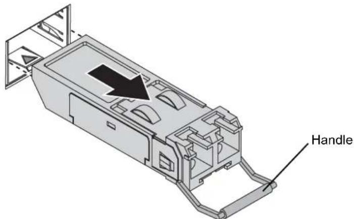
text_image
HandleFigure 2.16 Removing an SFP Transceiver
Note!Replace the dust plug on the slot if you are not installing a transceiver. The dust plug protects hardware from dust contamination.

2.2.4 Ethernet Connection
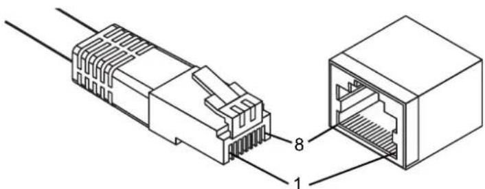
2.2.4.1 RJ45 Ethernet Cable Wiring
For RJ45 connectors, data-quality, twisted pair cabling (rated CAT5 or better) is recommended. The connector bodies on the RJ45 Ethernet ports are metallic and connected to the GND terminal. For best performance, use shielded cabling. Shielded cabling may be used to provide further protection.
| Straight-thru Cable Wiring Cross-over Cable Wiring |
| Pin 1 Pin 1 Pin 1 Pin 3 |
| Pin 2 Pin 2 Pin 2 Pin 6 |
| Pin 3 Pin 3 Pin 3 Pin 1 |
| Pin 6 Pin 6 Pin 6 Pin 2 |
text_image
Technical diagram showing two Ethernet connectors with labeled ports and connection pointsFigure 2.17 Ethernet Plug & Connector Pin Position
Maximum cable length: 100 meters (328 ft.) for 10/100/1000BaseT.
2.2.5 Fiber Connection
2.2.5.1 Fiber Cable Usage
Twisted-pair segment can use unshielded twisted pair (UTP) or shielded twisted pair (STP) cabling. The cable between the link partner (switch, hub, workstation, etc.) and the converter, must be less than 100 meters (328 ft.) long and comply with the IEEE 802.3ab 1000Base-T standard for Category 5e or above.
Fiber segment using single-mode connector type must use 9/125μm single-mode cable. You can connect two devices in the distance of 10 kilometers in full-duplex operation. For half-duplex operation, the recommended maximum distance is 412 meters (1,352 ft.).
Fiber segment using multi-mode connector type must use 50 or 62.5/125μm multimode fiber cable. You can connect two devices up to a 550 meters (1,804.46 ft.) distance.
2.2.5.2 Fiber Connection
The EKI-2741LXI or EKI-2741SXI has the SC type fiber port in single mode (10Km) or multi mode (550m). When you connect the fiber port to another one, please follow the below figure to connect it. Wrong connection will not allow the port to work normally.
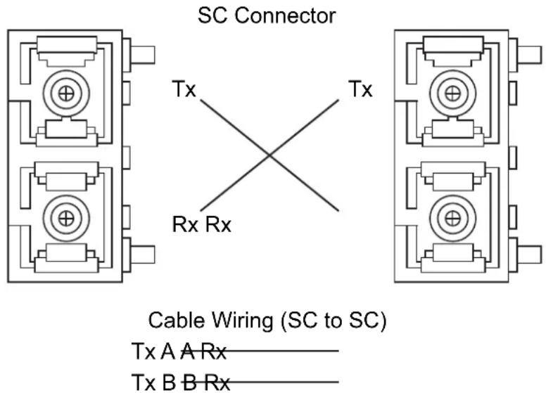
text_image
SC Connector Tx Tx Rx Rx Cable Wiring (SC to SC) Tx A A Rx——— Tx B B Rx———Figure 2.18 Pin Assignment of the SC Connector
Note! This is a Class 1 Laser/LED product. Don't stare into the Laser/LED Beam.

The EKI-2741LXI or EKI-2741SXI both have 1 x RJ-45 port that supports connection to 1000 Mbps Ethernet and half or full duplex operation. Both EKI-2741LXI and EKI-2741SXI can be connected to other hubs or switches through a twisted-pair straight through the cable or a crossover cable up to 100m long. The connection can be made from any TX port of the EKI-2741LXI or EKI-2741SXI (MDI-X) to another hub or switch either MDI-X or uplink MDI port.
Both EKI-2741LXI and EKI-2741SXI supports auto-crossover to make networking more easy and flexible. You can connect any RJ-45 (MDI-X) station port on the switch to any device such as a switch, bridge or router.
2.2.6 Power Connection
2.2.6.1 Overview
Warning!Power down and disconnect the power cord before servicing or wiring the serial device server.

Caution! Do not disconnect modules or cabling unless the power is first switched off.

The device only supports the voltage outlined in the type plate. Do not use any other power components except those specifically designated for the serial device server.
Caution! Disconnect the power cord before installation or cable wiring.

The EKI-2741FI/LXI/SXI supports dual 12 to 48 VDC power inputs and power-fail relay output.
The following figure illustrates a P-Fail alarm application example. The P-Fail alarm contacts are visible on the front view of the terminal block.
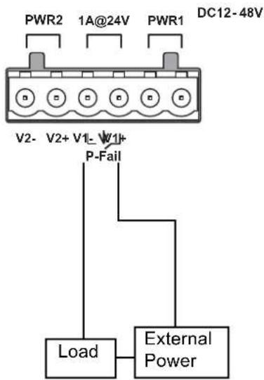
text_image
PWR2 1A@24V PWR1 DC12-48V V2-V2+ V1-W1+ P-Fail Load External PowerFigure 2.19 Power Wiring for EKI-2741FI/LXI/SXI
You can connect an alarm indicator, buzzer or other signaling equipment through the relay output. The relay opens if power input 1 or 2 fails. In a wiring example where an LED is connected to the relay output, the LED would be off in an Open state.
Chapter 3
Troubleshooting
3.1 Troubleshooting
1. Power Input
Verify that is using the right power cord/adapter (+12\~48 VDC), please don't use the power adaptor with DC output voltage higher than 48V, or it will burn this converter down.
2. Cable
Select the proper UTP/Fiber cable to construct your network. The single-mode converter must use single-mode fiber cable. Please check that you are using the right cable.
3. DIP Switch
Check the configuration DIP switch. It must be setting in the same operation mode with the link partner.
4. Diagnosing LED Indicators
The switch can be easily monitored through panel indicators, which describes common problems user may encounter and where user can find possible solutions, to assist in identifying.
If the power indicator does not light up when the power cord is plugged in, user may have a problem with power cord. Then check for loose power connections, power losses or surges at power outlet. If user still cannot resolve the problem, contact the local dealer for assistance.
If the Industrial switch LED indicators are normal and the connected cables are correct but the packets still cannot transmit, please check your system's Ethernet devices configuration or status.
ADVANTECH
Enabling an Intelligent Planet
www.advantech.com
Please verify specifications before quoting. This guide is intended for reference purposes only.
All product specifications are subject to change without notice.
No part of this publication may be reproduced in any form or by any means, electronic, photocopying, recording or otherwise, without prior written permission of the publisher.
All brand and product names are trademarks or registered trademarks of their respective companies.
© 2017 Advantech Co., Ltd.