MIC-715-NXA1 - Unknown Advantech - Free user manual and instructions
Find the device manual for free MIC-715-NXA1 Advantech in PDF.

User questions about MIC-715-NXA1 Advantech
0 question about this device. Answer the ones you know or ask your own.
Ask a new question about this device
Download the instructions for your Unknown in PDF format for free! Find your manual MIC-715-NXA1 - Advantech and take your electronic device back in hand. On this page are published all the documents necessary for the use of your device. MIC-715-NXA1 by Advantech.
USER MANUAL MIC-715-NXA1 Advantech
natural_image
Technical line drawing of a server rack with an AD-UNTECH unit, showing internal circuitry and mounting hardware (no text or symbols beyond branding)MIC-715
Ruggedized AI Inference System based on NVIDIA® Jetson Xavier NX
The documentation and the software included with this product are copyrighted 2022 by Advantech Co., Ltd. All rights are reserved. Advantech Co., Ltd. reserves the right to make improvements in the products described in this manual at any time without notice. No part of this manual may be reproduced, copied, translated, or transmitted in any form or by any means without the prior written permission of Advantech Co., Ltd. The information provided in this manual is intended to be accurate and reliable. However, Advantech Co., Ltd. assumes no responsibility for its use, nor for any infringements of the rights of third parties that may result from its use.
NVIDIA is a trademark of the NVIDIA Corporation.
All other product names or trademarks are properties of their respective owners.
Printed in Taiwan August 2022
Advantech warrants the original purchaser that each of its products will be free from defects in materials and workmanship for two years from the date of purchase.
This warranty does not apply to any products that have been repaired or altered by persons other than repair personnel authorized by Advantech, or products that have been subject to misuse, abuse, accident, or improper installation. Advantech assumes no liability under the terms of this warranty as a consequence of such events.
Because of Advantech's high quality-control standards and rigorous testing, most customers never need to use our repair service. If an Advantech product is defective, it will be repaired or replaced free of charge during the warranty period. For out-of-warranty repairs, customers will be billed according to the cost of replacement materials, service time, and freight. Please consult your dealer for more details.
If you believe your product is defective, follow the steps outlined below.
- Collect all the information about the problem encountered. (For example, CPU speed, Advantech products used, other hardware and software used, etc.) Note anything abnormal and list any onscreen messages displayed when the problem occurs.
- Call your dealer and describe the problem. Please have your manual, product, and any helpful information readily available.
- If your product is diagnosed as defective, obtain a return merchandise authorization (RMA) number from your dealer. This allows us to process your return more quickly.
- Carefully pack the defective product, a completed Repair and Replacement Order Card, and a proof of purchase date (such as a photocopy of your sales receipt) into a shippable container. Products returned without a proof of purchase date are not eligible for warranty service.
- Write the RMA number clearly on the outside of the package and ship the package prepaid to your dealer.
This equipment has been tested and found to comply with the limits for a Class A digital device, pursuant to part 15 of the FCC Rules. These limits are designed to provide reasonable protection against harmful interference when the equipment is operated in a commercial environment. This equipment generates, uses, and can radiate radio frequency energy and, if not installed and used in accordance with the instruction manual, may cause harmful interference to radio communications. Operation of this equipment in a residential area is likely to cause harmful interference. In this event, users are required to correct the interference at their own expense.
FCC A 级
Before system installation, check that the items listed below are included and in good condition. If any item does not accord with the list, contact your dealer immediately.
MIC-715
■ 1 x User manual (online download)
1 x China RoHS
■ 1 x Micro USB cable
■ 1 x Waterproof 6pin cable
■ 2 x MiniPCIe screw + 1 x M.2 screw
For more information on this and other Advantech products, please visit our website at:
http://www.advantech.com
For technical support and service, please visit our support website for MIC-715 at:
https://advt.ch/mic-715
Register your products on our website and get 2 months extra warranty for Free at:
http://www.register.advantech.com
- Read these safety instructions carefully.
- Retain this user manual for future reference.
- Disconnect the equipment from all power outlets before cleaning. Use only a damp cloth for cleaning. Do not use liquid or spray detergents.
- For pluggable equipment, the power outlet socket must be located near the equipment and easily accessible.
- Protect the equipment from humidity.
- Place the equipment on a reliable surface during installation. Dropping or letting the equipment fall may cause damage.
- The openings on the enclosure are for air convection. Protect the equipment from overheating. Do not cover the openings.
- Ensure that the voltage of the power source is correct before connecting the equipment to a power outlet.
- Position the power cord away from high-traffic areas. Do not place anything over the power cord.
- All cautions and warnings on the equipment should be noted.
- If the equipment is not used for a long time, disconnect it from the power source to avoid damage from transient overvoltage.
- Never pour liquid into an opening. This may cause fire or electrical shock.
- Never open the equipment. For safety reasons, the equipment should be opened only by qualified service personnel.
- If any of the following occurs, have the equipment checked by service personnel:
■ The power cord or plug is damaged. - Liquid has penetrated the equipment.
■ The equipment has been exposed to moisture.
The equipment is malfunctioning, or does not operate according to the user manual.
■ The equipment has been dropped and damaged.
■ The equipment shows obvious signs of breakage.
DISCLAIMER: These instructions are provided according to IEC 704-1 standards. Advantech disclaims all responsibility for the accuracy of any statements contained herein.
Follow these simple precautions to protect yourself from harm and the products from damage.
To avoid electrical shock, always disconnect the power from the PC chassis before manual handling. Do not touch any components on the CPU card or other cards while the PC is powered on.
Danger of explosion if battery is incorrectly replaced. Replace only with same or equivalent type recommended by the manufacture. Discard used batteries according to the manufacturer's instructions.
■ Replacement of a battery with an incorrect type that can defeat a safeguard
■ Disposal of a battery into fire or a hot oven, or mechanically crushing or cutting of a battery, that can result in an explosion.
■ Leaving a battery in an extremely high temperature surrounding environment that can result in an explosion or the leakage of flammable liquid or gas.
A battery subjected to extremely low air pressure that may result in an explosion or the leakage of flammable liquid or gas.
ATTENTION:
Chapter 1 General Introduction
概述
產品資訊1
1.1 Introduction/产品简介/產品簡介 2
Chapter 2 H/W Installation
硬件安装
硬體安裝7
2.1 I/O Overview/1/0 概观/1/0 概觀 8
2.2 Connectors/接口/介面 9
2.2.1 M16 Power Connector /电源端口/電源埠 9
2.2.2 4-CH M12 PoE LAN Ports 9
Figure 3.1 STM32L05 MCU Block Diagram 20
3.2 MCU STM32L0 Pin Assignment and Jumper Setting 21
Table 3.1: MCU Pin Assignment 21
Figure 3.2 SW1 Jumper.... 22
Table 3.2: SW1 Jumper Description.... 22
3.3 MCU Hardware Management 23
3.3.1 Vehicle Power Management (VPM).... 23
Figure 3.3 VPM State Machine.... 23
Table 3.3: VPM Parameters 23
Figure 3.4 Ignition Disable....26
3.3.2 |2C 28
Table 3.4: MIC-715PB I2C Device List.... 28
3.3.3 Firmware Upgrade 28
Figure 3.5 TM32flash update.... 28
3.4 MIC-715 UTILITY – VPM Controller (vpmctrl).... 29
3.4.1 vpmctrl Functions.... 29
Table 3.5: vpmctrl functions.... 29
3.4.2 NVidia Commands.... 31
3.4.3 Write the delay value to EEPROM.... 39
Figure 3.6 Delay time .... 39
3.5 Term and Definition.... 39
3.6 Reference 39
Chapter 1
General Introduction
概述
產品資訊
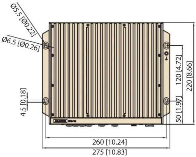
MIC-715 is embedded with NVIDIA Jetson Xavier NX, featuring compact fanless design in size 275 x 220 x 80 mm and 4.5 kg. MIC-715 has high tolerance in harsh environment, it has wide operating temperature from -25°C to 60°C. MIC-715 uses M12 connector, featuring IP67 rating for water and dust resistance. In order to manage the secure connection under vibration, all the I/O connectors are lockable.
Processor System -Jetson Xavier NX
Carmel CPU: ARMv8.2 (64-bit)HMP CPU architecture,3 x dual-core CPU clusters (6x NVIDIA Carmel processor cores) (Max. operating frequency: 1.9 GHz)
Volta GPU: 384 CUDA Core, 48 tensor cores, performance up to 21 TOPS (INT8) Max. operating frequency: 1100 MHz
■ Memory: 8GB LPDDR4
■ Storage: 16GB eMMC 5.1
Ethernet
■ 6 x Gigabit Ethernet (10/100/1000 Mbps), support 4 x PoE ports, IEEE 802.3af compliant
Peripheral I/O
1 x HDMI (Max. resolution 3840 x 2160 @ 60Hz. Waterproof connector, unmatching)
■ 2 x USB 3.0 (waterproof connector, unmatching)
■ 2 x CAN (Interface: M12 A-coded, 5-pin male)
■ 2 x Full size MiniPCIe with one SIM slot support
■ 1 x M.2 3052 B key + 1 x M.2 2280 M Key (NVMe, PCIex1)
■ 1 x OTG microUSB (Internal)
■ 1 x Micro SD card slot
Carmel CPU: ARMv8.2 (64-bit)HMP CPU architecture, 3 x dual-core CPU clusters (6x NVIDIA Carmel processor cores) (Max. Operating Frequency: 1.9 GHz)
Volta GPU: 384 CUDA Core, 48 Tensor Cores, Performance up to 21 TOPS (INT8) Max. operating frequency: 1100 MHz
■ Memory: 8GB LPDDR4
■ Storage: 16GB eMMC 5.1
网络:
6 x Gigabit Ethernet (10/100/1000 Mbps), support 4 x PoE ports, IEEE 802.3af compliant
I/0 界面:
1 x HDMI (Max. resolution 3840 x 2160 @ 60Hz. Waterproof connector, unmatching)
2 x USB 3.0 (waterproof connector, unmatching)
1 x USB 2.0(内部)
■ 2 x CAN (Interface: M12 A-coded, 5-pin male)
1 x RS-232/RS-422/RS-485
■ 2 x Full size MiniPCIe with one SIM slot support
1 x M. 2 3052 B key + 1 x M. 2 2280 M Key (NVMe, PCIex1)
1x OTG microUSB(内部)
1 x Reset 按钮 /1 x Recovery 按钮
1x Micro SD 卡槽
Carmel CPU: ARMv8.2 (64-bit) IIMP CPU architecture, 3 x dual-core CPU clusters (6x NVIDIA Carmel processor cores) (Max. Operating Frequency: 1.9 GHz)
Volta GPU: 384 CUDA Core, 48 Tensor Cores, Performance up to 21 TOPS (INT8) Max. operating frequency: 1100 MHz
■ Memory: 8GB LPDDR4
■ Storage: 16GB eMMC 5.1
網路:
6 x Gigabit Ethernet (10/100/1000 Mbps), support 4 x PoE ports, IEEE 802.3af compliant
I/0 介面:
natural_image
Simple line drawing of a rectangular frame with no text or symbolsUnit: mm
text_image
Ø5.5 [Ø0.22] Ø6.5 [Ø0.26] 4.5 [0.18] 260 [10.24] 275 [10.83] 120 [4.72] 50 [1.97] 220 [8.66]
natural_image
Simple line drawing of a rectangular door or cabinet (no text or symbols)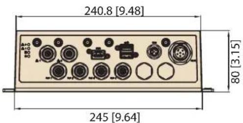
text_image
240.8 [9.48] 80 [3.15] 245 [9.64]natural_image
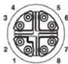
Exterior view of a modern office building (no signage)MIC-715 comes with M16 power connector in the front side of device.
natural_image
Back panel of a computer interface showing various ports and connectors (no readable text or symbols)
text_image
1 2 3 4 5 6 ① ② ③ ④ ⑤| Pin | Function |
| 1 | +Vin |
| 2 | +Vin |
| 3 | IGNITION |
| 4 | -Vin |
| 5 | -Vin |
| 6 | Power_ON Switch |
2.2.2 4-CH M12 PoE LAN Ports
MIC-715 comes with 4-channel M12 PoE LAN ports in the front side of the device.
text_image
Back panel of a computer interface showing labeled ports and connectors with a red highlight on the leftmost port.M12 X-Coding Female, 8 poles

| Pin | Function |
| 1 | MDI0+ (DC+) |
| 2 | MDI0- (DC+) |
| 3 | MDI1+ (DC-) |
| 4 | MDI1- (DC-) |
| 5 | MDI3+ |
| 6 | MDI3- |
| 7 | MDI2- |
| 8 | MDI2+ |
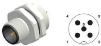
MIC-715 comes with one CANBus port in the front side of the device.
natural_image
Back panel of a computer interface showing ports, connectors, and a highlighted connector (no readable text or symbols)M12 A-coding Male, 5 poles
natural_image
Technical illustration of a white connector with threaded body and circular pinout (no text or symbols)*No pins for V+ and V-
| Pin | Function |
| 1 | CAN2_H |
| 2 | CAN2_L |
| 3 | GND |
| 4 | CAN1_H |
| 5 | CAN1_L |
2.2.4 M12 Ethernet (LAN) port/M12 网络端口/M12 網路连接埠
MIC-715 comes with 2 M12 LAN ports in the front side of the device.
text_image
Back panel of a device showing labeled ports and connectors with a red highlight on the left port.M12 X-Coding Female, 8 poles

natural_image
Close-up of a metallic connector with multiple pins, shown in two views (no text or symbols)| Pin | Function |
| 1 | MDI0+ |
| 2 | MDI0- |
| 3 | MDI1+ |
| 4 | MDI1- |
| 5 | MDI3+ |
| 6 | MDI3- |
| 7 | MDI2- |
| 8 | MDI2+ |
MIC-715 provides one microSD slot internally.
text_image
PUSH OPEN GF PWR1 PC50 N74 QF PWR2 QF PWR3 QF PWR4 QF PWR5 QF PWR6 QF PWR7 QF PWR8 QF PWR9 QF PWR10 QF PWR11 QF PWR12 QF PWR13 QF PWR14 QF PWR15 QF PWR16 QF PWR17 QF PWR18 QF PWR19 QF PWR20 QF PWR21 QF PWR22 QF PWR23 QF PWR24 QF PWR25 QF PWR26 QF PWR27 QF PWR28 QF PWR29 QF PWR30 QF PWR31 QF PWR32 QF PWR33 QF PWR34 QF PWR35 QF PWR36 QF PWR37 QF PWR38 QF PWR39 QF PWR40 QF PWR41 QF PWR42 QF PWR43 QF PWR44 QF PWR45 QF PWR46 QF PWR47 QF PWR48 QF PWR49 QF PWR50 QF PWR51 QF PWR52 QF PWR53 QF PWR54 QF PWR55 QF PWR56 QF PWR57 QF PWR58 QF PWR59 QF PWR60 QF PWR61 QF PWR62 QF PWR63 QF PWR64 QF PWR65 QF PWR66 QF PWR67 QF PWR68 QF PWR69 QF PWR70 QF PWR71 QF PWR72 QF PWR73 QF PWR74 QF PWR75 QF PWR76 QF PWR77 QF PWR78 QF PWR79 QF PWR80 QF PWR81 QF PWR82 QF PWR83 QF PWR84 QF PWR85 QF PWR86 QF PWR87 QF PWR88 QF PWR89 QF PWR90 QF PWR91 QF PWR92 QF PWR93 QF PWR94 QF PWR95 QF PWR96 QF PWR97 QF PWR98 QF PWR99 QF PWR1002.2.6 M.2 3052 Port/M.2 3052 端口/M.2 3052 埠
MIC-715 provides 1x M.2 3052 B key slot internally.
MIC-715 provides 1x M.2 2290 M key (NVMe, PCIe x1) slot internally.
MIC-715 provides 2 pcs mini-PCIE port internally.
text_image
Circuit board with labeled components and annotations, highlighting a red-circled area of interest on the circuit board.To update your MIC-715, you must be in Force USB Recovery Mode. When in Force USB Recovery Mode, you can update system software and write partition configuration to the device.
-
Please prepare one HOST PC. (About more HOST PC detail, please refer to software update SOP)
-
Before flashing MIC-715, you must turn MIC-715 into Force Recovery Mode manually.
(a) Shut down the MIC-715.
(b) Connect HOST PC and MIC-715 Internal Micro USB with USB cable.
(c) Press and hold internal SW_REC1 button.
(e) After 5s release the SW_REC1 button.
Make sure MIC-715 is recognized by HOST PC successfully:
Type command: Isusb in HOST PC. If you see: NVIDIA Corp. It means MIC-715 is in recovery mode.
* Root password of MIC-715: mic-715
natural_image
Technical line drawing of an electronic device chassis with exposed components and mounting holes (no text or labels)
text_image
mini PCIe module mini PCIe module M. 2-3052 module M. 2-2280 modulePart number notice:
- For M.2 module:
Screw: 1930007593-01
Thermal pad: (M.2-3052)1990030086N000
(M.2-2280)1990026184N000
- For miniPCIe:
Screw: 1930006203-01
Thermal pad: 1990032899N000
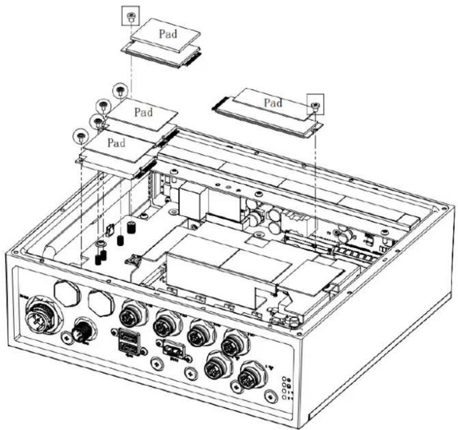
text_image
Pad Pad Pad Pad 0000Part number notice:
Screw: 1930008772
Heat spreader: 1970004928T000
Thermal pad: 1990021446N000

text_image
For M. 2-2260 Thermal pad (Between Bottom cover and Heat spreader) For 2 sets mini PCIe and M. 2-3052Chapter
3
MCU
3.1 Introduction
This document is used to introduce the MCU functionalities below.
– Vehicle Power Management (VPM) for Ignition
– GPIO configuration or pin assignments
- I2C device list
flowchart
graph TD
    A["Term. 4P"] -->|9~36V (24V)| B["Power Protect LT_LT4363IDE-2"]
    C["WaferBox"] -->|IGNITION PANSWIN#| D["LT3012EDE"]
    D -->|2.2V| E["APL5930CQBI"]
    E -->|2.2V| F["+V3.3_DCIN"]
    F --> G["ST STM32L051C8T6"]
    G --> H["MCU_RST"]
    G --> I["MCU_FW_UPDATE"]
    G --> J["UART0"]
    G --> K["MCU_I2C1"]
    K --> L["MOS"]
    L --> M["PG_PWRBRD"]
    L --> N["PANSWIN#"]
    L --> O["PG_MAIN_PWR#"]
    G --> P["SWD"]
    P --> Q["DIP_SW 4P"]
    G --> R["EEPROM"]
    R --> S["QSENSOR"]
    R --> T["RTC"]
    G --> U["EN"]
    G --> V["EN"]
    G --> W["EN"]
    G --> X["EN"]
    G --> Y["EN"]
    G --> Z["EN"]
    G --> AA["EN"]
    G --> AB["EN"]
    G --> AC["EN"]
    G --> AD["EN"]
    G --> AE["EN"]
    G --> AF["EN"]
    G --> AG["EN"]
    G --> AH["EN"]
    G --> AI["EN"]
    G --> AJ["EN"]
    G --> AK["EN"]
    G --> AL["EN"]
    G --> AM["EN"]
    G --> AN["EN"]
    G --> AO["EN"]
    G --> AP["EN"]
    G --> AQ["EN"]
    G --> AR["EN"]
    G --> AS["EN"]
    G --> AT["EN"]
    G --> AU["EN"]
    G --> AV["EN"]
    G --> AW["EN"]
    G --> AX["EN"]
    G --> AY["EN"]
    G --> AZ["EN"]
    G --> BA["EN"]
    G --> BB["EN"]
    G --> BC["EN"]
    G --> BD["EN"]
    G --> BE["EN"]
    G --> BF["EN"]
    G --> BG["EN"]
    G --> BH["EN"]
    G --> BI["EN"]
    G --> BJ["EN"]
    G --> BK["EN"]
    G --> BL["EN"]
    G --> BM["EN"]
    G --> BN["EN"]
    G --> BO["EN"]
    G --> BP["EN"]
    G --> BQ["EN"]
    G --> BR["EN"]
    G --> BS["EN"]
    G --> BT["EN"]
    G --> BU["EN"]
    G --> BV["EN"]
    G --> BW["EN"]
    G --> BX["EN"]
    G --> BY["EN"]
    G --> BZ["EN"]
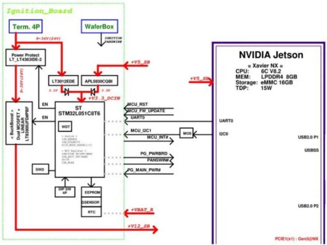
Figure 3.1 STM32L05 MCU Block Diagram
3.2 MCU STM32L0 Pin Assignment and Jumper Setting
| Table 3.1: MCU Pin Assignment | |||
| Port Port | Type Signal Name Notice | ||
| PA1 GPI | IGN_ENABLE | Low: ignition DisableHigh: ignition Enable | |
| PA2 GPI | IGN_POLARITY | Low: IGN_SW(PB2)=Low, thenEnable SystemHigh: IGN_SW(PB2)=High, thenEnable System | |
| PA3 GPI | DCIN_MODE_RANGE0 | DCIN_MODE_RANGEGE[1:0] :00 => 12V, 01 => 24V, 10 => 37.5V,11 => 48V | |
| PA4 GPI | DCIN_MODE_RANGE1 | ||
| PA6 ADC | _IN6 ADC_12V_24V ADC | ||
| PA7 ADC | _IN7 ADC_37V_48V ADC | ||
| PA9 USART1_TX | USART1_TX | Firmware upgrade | |
| PA10 | USART1_RX | USART1_RX | |
| PA12 | GPO | MCU_LT4363_SHDN | Low: Enable DCINHigh: Disable DCIN |
| PB1 | GPI PG_DCIN# | Low: DCIN Power GoodHigh: DCIN Power not ready | |
| PB2 | GPI IGN_SW | Low: IGN_POLARITY(PA2)=Low,then Enable SystemHigh: IGN_POLARITY(PA2)=High,then Enable System | |
| PB3 | GPO | EN_B_+V12SB | Low: Disable +V12SBHigh: Enable +V12SB |
| PB4 | GPI +V12_SB_D_PG# | Low: +V12_SB Power GoodHigh: +V12_SB Power not ready | |
| PB5 | GPO | PG_PWRBRD | Low: MIC-715PB Power not readyHigh: MIC-715PB Power Good |
| PB6 | GPI DCIN_M_PANSWIN# | Power BTN# input | |
| PB7 | GPO | DCIN MCU_B PAN-SWIN# | Power BTN# output |
| PB8 | I2C1_SCL | MCU_I2C1_R_SCL | Communication between System and MCU |
| PB9 | I2C1_SDA MCU | I2C1_R_SDA | |
| PB10 | I2C2_SCL | MCU_I2C2_R_SCL | Read/Write RTC & EEPROM & G-SENSOR |
| PB11 | I2C2_SDA MCU | I2C2_R_SDA | |
| PB12 | GPO | MCU_INT# | Communication between System and MCU |

text_image
+V3.3_STLINK RN1 10K 5% 8 7 6 5 4 3 2 1 SW1 1 ON 2 7 3 6 4 5 CHS-04TB(2) IGN_ENABLE IGN_POLARITY DCIN_MODE_RANGE0 DCIN_MODE_RANGE1Figure 3.2 SW1 Jumper
| Table 3.2: SW1 Jumper Description | ||
| Pin Name Description | ||
| 1 IGN_ENABLE | ON: ignition DisableOFF: ignition Enable (default) | |
| 2 IGN_POLARITY | ON: Active lowOFF: Active high (default) | |
| 3 DCIN_MODE_RANGE0 00: 12V (default) | 01: 24V10: 37.5V11: 48V | |
| 4 DCIN_MODE_RANGE1 | ||
3.3 MCU Hardware Management
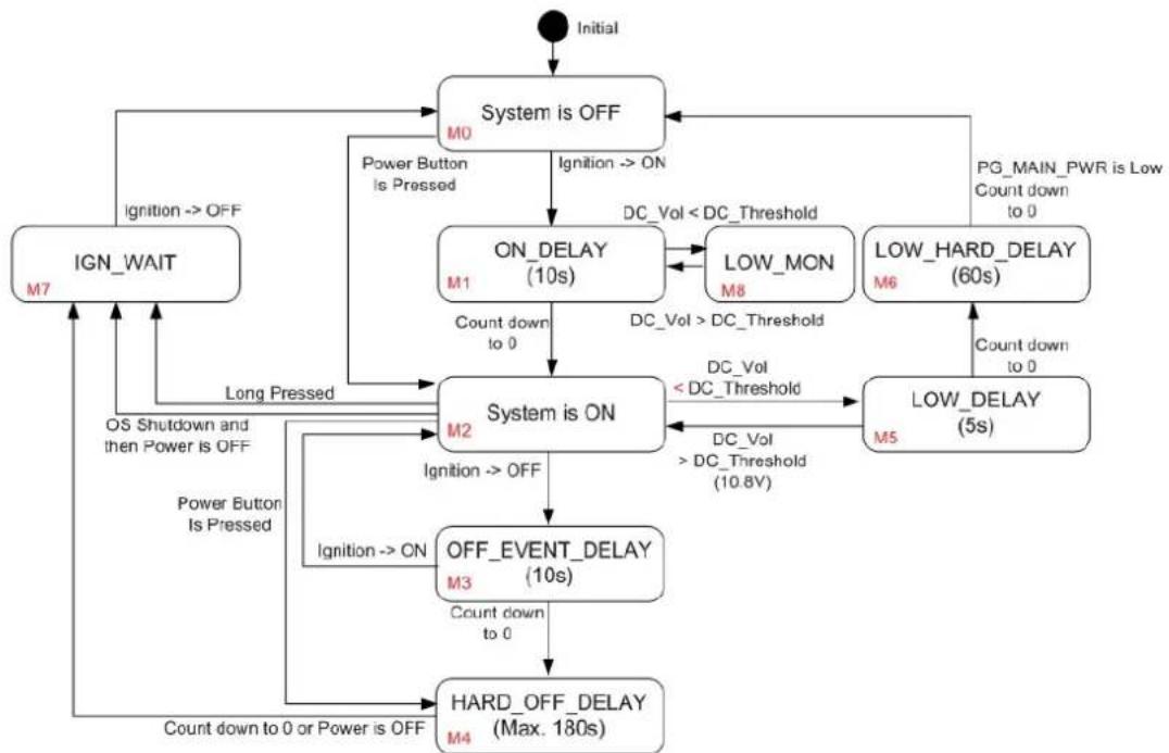
3.3.1 Vehicle Power Management (VPM)
The feature of Vehicle Power Management (VPM) is provided for users to fulfill the special requirements on in-vehicle applications. The following chart is the VPM state machine.
flowchart
graph TD
    A["Initial"] --> B["System is OFF"]
    B -->|Ignition --> ON| C["ON_DELAY (10s)"]
    C -->|Count down to 0| D["System is ON"]
    D -->|Ignition --> OFF| E["OFF_EVENT_DELAY (10s)"]
    E -->|Count down to 0 or Power is OFF| F["HARD_OFF_DELAY (Max. 180s)"]
    F -->|Count down to 0 or Power is OFF| G["IGN_WAIT"]
    G -->|Ignition --> OFF| H["Power Button Is Pressed"]
    H --> I["ON_DELAY (10s)"]
    I -->|DC_Vol < DC_Threshold| J["LOW_MON M8"]
    J -->|DC_Vol > DC_Threshold| K["LOW_DELAY (60s)"]
    K -->|Count down to 0| L["PG_MAIN_PWR is Low Count down to 0"]
    L --> B
    D -->|DC_Vol < DC_Threshold| M["LOW_DELAY (5s)"]
    M -->|DC_Vol > DC_Threshold (10.8V)| N["LOW_DELAY (60s)"]
    N -->|Count down to 0| O["Power Button is Pressed"]
    O --> P["ON_DELAY (10s)"]
    P -->|DC_Vol < DC_Threshold| Q["LOW_MON M8"]
    Q -->|DC_Vol > DC_Threshold| R["LOW_DELAY (60s)"]
    R -->|Count down to 0| S["PG_MAIN_PWR is Low Count down to 0"]
    S --> T["Power Button is Pressed"]
    T --> U["ON_DELAY (10s)"]
    U -->|DC_Vol < DC_Threshold| V["LOW_MON M8"]
    V -->|DC_Vol > DC_Threshold| W["LOW_DELAY (60s)"]
    W -->|Count down to 0| X["PG_MAIN_PWR is Low Count down to 0"]
    X --> Y["Power Button is Pressed"]
    Y --> Z["ON_DELAY (10s)"]
    Z -->|DC_Vol < DC_Threshold| AA["LOW_MON M8"]
    AA -->|DC_Vol > DC_Threshold| AB["LOW_DELAY (60s)"]
    AB -->|Count down to 0| AC["PG_MAIN_PWR is Low Count down to 0"]
Figure 3.3 VPM State Machine
The table below lists the user programmable parameters for VPM features:
| Table 3.3: VPM Parameters | ||
| Name Default Value Acceptable range (*) | ||
| ON_DELAY 10 seconds 1-18000 seconds | ||
| OFF_EVENT_DELAY 10 seconds 1-18000 seconds | ||
| HARD_OFF_DELAY 180 seconds 1-18000 seconds | ||
| LOW_THRESHOLD (12 V mode) | 10.8V | 10.09-12.25V |
| LOW_DELAY | 5 seconds | 1-3600 seconds |
| LOW_HARD_DELAY | 60 seconds 1-3600 seconds | |
3.3.1.1 Ignition On/Off
1. Turn on the system by ignition
For the cases of in-vehicle applications, an ignition signal is often used to turn on or shut down the system. When the system is in the OFF state and the ignition is turned ON, MCU will count down for ON_DELAY second(s); once it counts to zero, the system will be turned on immediately.
The MCU boot console is shown as below.
000000.001 Board: MIC-715PB
000000.004 Version: 211001
000000.007 DCIN_MODE_RANGE0: 1
000000.011 DCIN_MODE_RANGE1: 1
000000.014 IGN_ENABLE: 1
000000.017 IGN_POLARITY: 0
000000.021 I2C dev RTC 0x30 ret = 0 reg[0] = 0x00
000000.026 I2C dev EEPROM 0x57 ret = 0 reg[0] = 0xff
000000.032 main:86 [M0: System is OFF
Note, the rework might be needed for the MCU UART console.
Change SW1 to HIGH and SW2 to LOW respectively, Ignition is enabled.
000000.036 main:89[M0: System is IGN_SW and IGN_POLARITY on 000000.064 _Batt_Low_power_status:434 12.11v 000010.079 main:112 [M1: ON Delay 000012.428 main:120 [M2: System is on 000013.521 _Batt_Low_power_status:434 12.01v 000014.626 _Batt_Low_power_status:434 12.00v 000015.731 _Batt_Low_power_status:434 12.00v 000016.836 _Batt_Low_power_status:434 12.02v 000017.941 _Batt_Low_power_status:434 12.01v 000019.046 _Batt_Low_power_status:434 12.00v 000020.151 _Batt_Low_power_status:434 12.01v 000021.256 _Batt_Low_power_status:434 12.00v 000022.361 _Batt_Low_power_status:434 11.96v 000023.466 _Batt_Low_power_status:434 11.99v 000024.571 _Batt_Low_power_status:434 11.98v
2. Shutdown the system by ignition
When the system is powered on and the ignition is turned off, the OFF_EVENT_DELAY will start to count down. During this stage, if the ignition is backed to ON, MCU will stop the countdown and reset the OFF_EVENT_DELAY value.
If OFF_EVENT_DELAY counts to zero, MCU will send an event (power button press) to the system and start to count down HARD_OFF_DELAY.
000127.657 main:261 [M3: OFF EVENT DELAY
000137.671 main:275 [M4: HARD OFF DELAY
000169.507 main:87 [M0: System is OFF
Note, NV idia will pop a "Power Off" dialog when entering the power off state.
3. Accidentally touched shutdown menu
When the user accidentally touches a button or shuts down in a short case, the OS will pop out a window and the system will start counting for 30s to shut down.
At this time, if the window is closed via the mouse, the system will consider the behavior mode of improper shutdown and start counting down for 180s to shut down.
000201.744 AT button: 1
000202.008 AT button: 2
000202.021 main:146 [M2-1: power button short off
000202.026 main:229 [M4: HARD OFF DELAY
000383.011 main:220 [M7: POWER OFF DELAY
Note, NV idia will pop a "Power Off" dialog when entering the power off state.
4. Power LED OFF behavior
When the user switches to any function, as long as the final path is related to the M7 Function, the green Power LED will light off. At this time, the user needs to manually turn the switch back to OFF, and the system will return to the System OFF stage then proceed to the power-on and power-off options that the user needs.
5. Low battery protection
To avoid draining out the car battery, low-battery protection is involved to ensure the car battery is able to start the vehicle. When the system is ON, MCU will monitor the car battery voltage. If the battery voltage is lower than a programmable threshold (LOW_THRESHOLD), MCU will go into LOW_DELAY stage and start to count down. During the stage of LOW_DELAY countdown, if battery voltage rises to above LOW_THRESHOLD, MCU will stop counting down and return to the System ON stage. If LOW_DELAY counts to zero, MCU will send an event (power button pressed) to notify the system and go into LOW_HARD_DELAY stage and start to count down. Once LOW_HARD_DELAY counts to zero, MCU will cut off the system power immediately to avoid draining out the car battery.
000065.165 main:117 [M2: System is ON
000111.509 main:252 [M5: LOW DELAY
000111.513 _Batt_Low_power_status:438 Batt low 10.8 10.43
000112.521 _Batt_Low_power_status:438 Batt low 10.8 9.90
000113.528 _Batt_Low_power_status:438 Batt low 10.8 9.90
000114.535 _Batt_Low_power_status:438 Batt low 10.8 9.89
000115.542 _Batt_Low_power_status:438 Batt low 10.8 9.90
000116.549 main:266 [M6: LOW HARD DELAY
000148.385 main:86 [M0: System is OFF
000148.389 main:89 [M0: System is IGN_SW and IGN_POLARITY on
000148.416 _Batt_Low_power_status:438 Batt low 10.8 10.10
000148.422 main:243 [M8: check Battery
000148.427 _Batt_Low_power_status:438 Batt low 10.8 10.10
000149.434 _Batt_Low_power_status:438 Batt low 10.8 10.10
000150.441 _Batt_Low_power_status:438 Batt low 10.8 10.10
000151.448 _Batt_Low_power_status:438 Batt low 10.8 10.10
000152.455 _Batt_Low_power_status:438 Batt low 10.8 10.10
000153.462 _Batt_Low_power_status:438 Batt low 10.8 10.10
000154.469 _Batt_Low_power_status:438 Batt low 10.8 10.10
Note, NV idia will pop a "Power Off" dialog when entering the power off state.
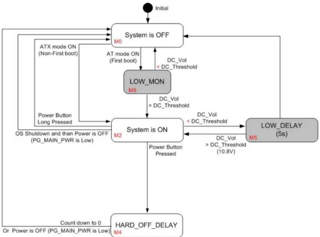
The feature of Vehicle Power Management (VPM) is provided for users to fulfill the special requirements on in-vehicle applications. The following chart is the VPM state machine.
flowchart
graph TD
    A["Initial"] --> B["System is OFF"]
    B --> C["AT mode ON (Non-First boot)"]
    B --> D["Power Button Long Pressed"]
    C --> E["LOW_MON M8"]
    D --> F["OS Shutdown and then Power is OFF (PG_MAIN_PWR is Low)"]
    E --> G["System is ON"]
    F --> G
    G --> H["HARD_OFF_DELAY M4"]
    H --> I["Count down to 0 Or Power is OFF (PG_MAIN_PWR is Low)"]
    B --> J["DC_Vol < DC_Threshold"]
    J --> K["Power Button Pressed"]
    K --> G
    G --> L["DC_Vol < DC_Threshold (10.8V)"]
    L --> M["LOW_DELAY (5s)"]
    M --> N["DC_Vol < DC_Threshold"]
    N --> G
    B --> O["DC_Vol < DC_Threshold"]
    O --> P["Power Button Pressed"]
    P --> G
Figure 3.4 Ignition Disable
1. Turn on the system when ignition disabled
For the cases of in-vehicle applications, an ignition signal is often used to turn on or shut down the system. When the system is in an OFF state and the ignition is disabled, after the AC is ON, the system will be turned on.
The MCU boot console is shown as below.
000000.001 Board: MIC-715PB
000000.004 Version: 211001
000000.008 DCIN_MODE_RANGE0: 1
000000.011 DCIN_MODE_RANGE1: 1
000000.015 IGN_ENABLE: 0
000000.018 IGN_POLARITY: 1
000000.021 I2C dev RTC 0x30 ret = 0 reg[0] = 0x00
000000.026 I2C dev EEPROM 0x57 ret = 0 reg[0] = 0xff
000000.032 main:321 [M0-1: AT mode system is on
000000.032_Batt_Low_power_status:438 12.46v
Note, the rework might be needed for the MCU UART console.
Change SW1 to LOW and SW2 to HIGH respectively, Ignition is disabled.
000004.417 main:323 [M2-1: AT mode system is on
000234.218 _Batt_Low_power_status:441 12.32v
000234.231 _Batt_Low_power_status:441 12.33v
000234.244 _Batt_Low_power_status:441 12.32v
000234.257 _Batt_Low_power_status:441 12.31v
000234.271 _Batt_Low_power_status:441 12.31v
000234.284 _Batt_Low_power_status:441 12.29v
000234.297 _Batt_Low_power_status:441 12.32
2. Shutdown the system by power button
When the system is powered on and the power button is long-pressed, the system will be powered off immediately. Afterward, once the power button is pressed again, the system will boot up with the ATX mode. When the system is powered on and the power button is short-pressed, the OS will pop out a window and start counting for 30 seconds to shut down. After the system has shut down, once the power button is pressed again, the system will boot up with the ATX mode.
000235.374_Batt_Low_power_status:441 12.30v
000235.600 button: 1
000235.630 button: 2
000235.883 button: 3
000236.136 button: 4
000236.389 button: 5
000236.642 button: 6
000236.644 main:365 [M2-1: power button short off
000236.650 main:411 [M4-1: HARD OFF DELAY
Note, NV idia will pop a "Power Off" dialog when entering the power off state.
3. Low battery protection
To avoid draining out the car battery, low-battery protection is involved to ensure the car battery is able to start the vehicle. When the system is ON, MCU will monitor the car battery voltage. If the battery voltage is lower than a programmable threshold (LOW_THRESHOLD), MCU will go into LOW_DELAY stage and start to count down. Once LOW_DELAY counts to zero, MCU will cut off the system power immediately to avoid draining out the car battery. Afterward, once the power button is pressed, MCU will send an event (power button pressed) to notify the system to boot up.
000010.453 main:323 [M2-1: AT mode system is on
000099.601 _Batt_Low_power_status:445 Batt low 10.8 10.49
000099.608 main:393 [M5-1: LOW DELAY
000099.612 _Batt_Low_power_status:445 Batt low 10.8 10.48
000100.620 _Batt_Low_power_status:445 Batt low 10.8 8.67
000101.627 _Batt_Low_power_status:445 Batt low 10.8 9.28
000102.634 _Batt_Low_power_status:445 Batt low 10.8 9.65
000103.641 _Batt_Low_power_status:445 Batt low 10.8 9.66
000161.495 main:334 [M0-1: Power Button on
000083.863 _Batt_Low_power_status:412 12.66v
000083.868 main:323 [M2-1: AT mode system is on
3.3.2 I2C
The I2C device table is shown as below.
| Table 3.4: MIC-715PB I2C Device List | |||
| Bus I2C Address Name Description | |||
| 2 0x30-0x37 RTC SEIKO_S-35390A | |||
| 2 0x57 EEPROM ST_M24512-RMN6TP | |||
The I2C devices of RTC, G-Sensor and EEPROM are present if ret=0.
000000.021 I2C dev RTC 0x30 ret= 0 reg[0] = 0x00
000000.027 I2C dev EEPROM 0x57 ret= 0 reg[0] = 0xff
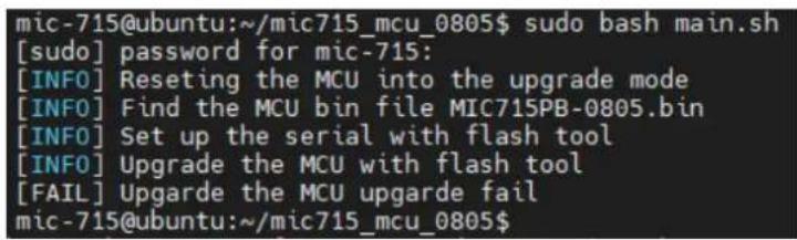
3.3.3 Firmware Upgrade
The firmware can be upgraded via ST-LINK or the Linux stm32flash utility on the host.
<h1 id="tar-jxf-mic715_mcu_0805tbz2">tar -jxf mic715_mcu_0805.tbz2</h1>
<h1 id="cd-mic715_mic">cd mic715_mic</h1>
<h1 id="sudo-bash-mainsh">sudo bash main.sh</h1>
It's recommended to have a clear power cycle after the firmware upgrade.
text_image
mic-715@ubuntu:~/mic715_mcu_0805$ sudo bash main.sh [sudo] password for mic-715: [INFO] Resetting the MCU into the upgrade mode [INFO] Find the MCU bin file MIC715PB-0805.bin [INFO] Set up the serial with flash tool [INFO] Upgrade the MCU with flash tool [FAIL] Upgarde the MCU upgarde fail mic-715@ubuntu:~/mic715_mcu_0805$Figure 3.5 TM32flash update
3.4 MIC-715 UTILITY – VPM Controller (vpmctrl)
The Vehicle Power Management (VPM) Controller (vpmctrl) is a host utility, it allows user to interact with MCU. The vpmctrl utility provides the command line interface (CLI) for the user operations. User can operate the features below by the vpmctrl utility.
■ Vehicle Power Management (VPM)
■ Monitor the system health (voltages)
Note! It's necessary to get the Root or Super User (sudo) permission during using the vpmctrl utility.

3.4.1 vpmctrl Functions
Currently the vpmctrl utility provides the functions as below. This command "vpmctrl help" will show the vpmctrl utility usage.
■ Access the MCU information.
■ Access DC information. (+12V/+24V/+37.5V/+48V)
■ Access Ignition information.
■ Access AT information
■ Access board-id information.
■ Access Delay information.
■ Access LOW VOL ERROR information.
■ Access reset MCU information.
■ Access VPM information.
| Table 3.5: vpmctrl functions | ||
| Function MCU Command Description | ||
| Access MCU information | get-api-version Get API Version | |
| get-firmware-version | Get MCU Firmware Version | |
| Access DC information | get-dc-mode | Get DC Mode |
| get-dc-voltage | Get DC Voltage (mV) | |
| get-12v-threshold | Get 12V Threshold (mV) | |
| set-12v-threshold | Set 12V Threshold (mV) | |
| Access Ignition information | get-ignition-status | Get Ignition Status |
| get-ignition-setting | Get Ignition Setting | |
| Access AT information | get-atx-mode | Get AT/ATX Mode |
| Access board-id information | get-board-product-id | Get Board Product ID |
| get-board-rev-num | Board Revision Number | |
| get-board-serial-num | Board Serial Number | |
| set-board-serial-num | Board Serial Number | |
Table 3.5: vpmctrl functions
| Access Delay information | get-low-delay LOW_DELAY | |
| set-low-delay LOW_DELAY | ||
| get-low-hard-delay LOW_HARD_DELAY | ||
| set-low-hard-delay LOW_HARD_DELAY | ||
| get-on-delay ON_DELAY | ||
| set-on-delay ON_DELAY | ||
| get-off-event-delay OFF_EVENT_DELAY | ||
| set-off-event-delay OFF_EVENT_DELAY | ||
| get-hard-off-delay HARD_OFF_DELAY | ||
| set-hard-off-delay HARD_OFF_DELAY | ||
| Access LOW VOL ERROR information | get-low-vol-err-count Get Low Voltage Error Count | |
| clear-low-vol-err-count Clear Voltage Error Count | ||
| Access reset MCU information | reset-mcu | Reset MCU |
| Access VPM information | get-all-info | Get All VPM Information |
Usage:
./vpmctrl.sh <cmd> [<arg>]
<cmd> : one of VPM commands below.
    get-api-version : Get API Version.
    get-firmware-version : Get Firmware Version.
    get-dc-mode : Get DC Mode.
    get-dc-voltage : Get DC Voltage (mV).
    get-ignition-status : Get Ignition Status.
    get-ignition-setting : Get Ignition Setting.
    get-atx-mode : Get AT/ATX Mode.
    get-board-product-id : Get Board Product ID.
    get-board-rev-num : Get Board Revision Number.
    get-board-serial-num : Get Board Serial Number.
    set-board-serial-num : Set Board Serial Number.
    get-low-delay : Get LOW_DELAY.
    set-low-delay : Set LOW_DELAY.
    get-low-hard-delay : Get LOW_HARD_DELAY
    set-low-hard-delay : Set LOW_HARD_DELAY.
    get-12v-threshold : Get 12V Threshold (mV).
    set-12v-threshold : Set 12V Threshold (mV).
    get-on-delay : Get ON_DELAY.
    set-on-delay : Set ON_DELAY.
    get-off-event-delay : Get OFF_EVENT_DELAY.
    set-off-event-delay : Set OFF_EVENT_DELAY.
    get-hard-off-delay : Get HARD_OFF_DELAY.
    set-hard-off-delay : Set HARD_OFF_DELAY.
    get-low-vol-err-count : Get Low Voltage Error Count.
    clear-low-vol-err-count: Clear Voltage Error Count.
    reset-mcu : Reset MCU.
    get-all-info : Get All VPM Information.
<arg> : VPM command argument to set, '?' for help.
3.4.2 NVidia Commands
The vpmctrl utility provides the NV idia BSP commands with the syntax and structure below for the user interaction. About the explanation of each command, please refer to the sections below for more details.
3.4.2.1 vpmctrl get-api-version
This command will get the API version.
Usage:
./vpmctrl get-api-version [?]
where
'?' : for help.
Example:
$ sudo ./vpmctrl get-api-version
API ver: 0
3.4.2.2 vpmctrl get-firmware-version
This command will get the MCU firmware version.
Usage:
./vpmctrl get-firmware-version [?]
where
'?' : for help.
Example:
$ sudo ./vpmctrl get-firmware-version
FW ver: 211008
3.4.2.3 vpmctrl get-dc-mode
This command will get the DC mode.
Usage:
./vpmctrl get-dc-mode [?]
where
'?' : for help.
Example:
$ sudo ./vpmctrl get-dc-mode
DC mode: 0 (12V)
3.4.2.4 vpmctrl get-dc-voltage
This command will get the DC voltage.
Usage:
./vpmctrl get-dc-voltage [?]
where
'?' : for help.
Example:
$ sudo ./vpmctrl get-dc-voltage
DC volt: 12094 mV
3.4.2.5 vpmctrl get-ignition-status
This command will get the ignition status.
Usage:
./vpmctrl get-ignition-status [?]
where
'?' : for help.
Example:
$ sudo ./vpmctrl get-ignition-status
IGN status: 0 (off)
3.4.2.6 vpmctrl get-ignition-setting
This command will get the ignition setting.
Usage:
./vpmctrl get-ignition-setting [?]
where
'?' : for help.
Example:
$ sudo ./vpmctrl get-ignition-setting
IGN setting: 1 (enable)
3.4.2.7 vpmctrl get-atx-mode
This command will get the AT/ATX mode.
Usage:
./vpmctrl get-atx-mode [?]
where
'?' : for help.
Example:
$ sudo ./vpmctrl get-atx-mode
AT/ATX mode: 1 (ATX)
3.4.2.8 vpmctrl get-board-product-id
This command will get the board product ID.
Usage:
./vpmctrl get-board-product-id [?]
where
'?' : for help.
Example:
$ sudo ./vpmctrl get-board-product-id
Board product ID: MIC-715PB
3.4.2.9 vpmctrl get-board-rev-num
This command will get the board revision number.
Usage:
./vpmctrl get-board-rev-num [?]
where
'?' : for help.
Example:
$ sudo ./vpmctrl get-board-rev-num
Board revision number: 0 (A101-1)
3.4.2.10 vpmctrl get-board-serial-num
This command will get the board serial number.
Usage:
./vpmctrl get-board-serial-num [?]
where
'?' : for help.
Example:
$ sudo ./vpmctrl get-board-serial-num
Board SN: ESPE012345
3.4.2.11 vpmctrl set-board-serial-num
This command will set the board serial number.
Usage:
./vpmctrl set-board-serial-num <sn>
./vpmctrl set-board-serial-num [?]

where
<sn> : board serial number to set.
'?' : for help.

Example:
$ sudo ./vpmctrl set-board-serial-num ESPE012345
Set board SN: 0 (OK)
3.4.2.12 vpmctrl get-low-delay
This command will get the LOW_DELAY (0-3600 sec).
Usage:
./vpmctrl get-low-delay [?]
where
'?' : for help.
Example:$ sudo ./vpmctrl get-low-delay
LOW_DELAY: 5 sec
3.4.2.13 vpmctrl set-low-delay
This command will the set low delay.
Usage:
./vpmctrl set-low-delay <delay>
./vpmctrl set-low-delay [?]

where
<delay> : LOW_DELAY (0-3600 sec) to set.
'?' : for help.

Example:
$ sudo ./vpmctrl set-low-delay 5
Set LOW_DELAY: 0 (OK)
3.4.2.14 vpmctrl get-low-hard-delay
This command will get the LOW_HARD_DELAY (0-3600 sec).
Usage:
./vpmctrl get-low-hard-delay [?]
where
'?' : for help.
Example:
$ sudo ./vpmctrl get-low-hard-delay
LOW_HARD_DELAY: 60 sec
3.4.2.15 vpmctrl set-low-hard-delay
This command will set the LOW_HARD_DELAY (0-3600 sec).
Usage:
./vpmctrl set-low-hard-delay <delay>
./vpmctrl set-low-hard-delay [?]

where
<delay> : LOW_HARD_DELAY (0-3600 sec) to set.
'?' : for help.

Example:
$ sudo ./vpmctrl set-low-hard-delay 60
Set LOW_HARD_DELAY: 0 (OK)
3.4.2.16 vpmctrl get-12v-threshold
This command will get the 12V threshold (10090-12250 mV).
Usage:
./vpmctrl get-12v-threshold [?]
where
'?' : for help.
Example:
$ sudo ./vpmctrl get-12v-threshold
12V Threshold: 10800 mV
3.4.2.17 vpmctrl set-12v-threshold
This command will set the 12V threshold (10090-12250 mV).
Usage:
./vpmctrl set-12v-threshold <thr>
./vpmctrl set-12v-threshold [?]

where
<thr> : 12V Threshold (10090-12250 mV) to set.
'?' : for help.

Example:
$ sudo ./vpmctrl set-12v-threshold 10800
Set 12V Threshold: 0 (OK)
3.4.2.18 vpmctrl get-on-delay
This command will get the ON_DELAY (0-18000 sec).
Usage:
./vpmctrl get-on-delay [?]
where
'?' : for help.
Example:
$ sudo ./vpmctrl get-on-delay
ON_DELAY: 10 sec
3.4.2.19 vpmctrl set-on-delay
This command will set the ON_DELAY (0-18000 sec).
Usage:
./vpmctrl set-on-delay <delay>
./vpmctrl set-on-delay [?]

where
<delay> : ON_DELAY (0-18000 sec) to set.
'?' : for help.

Example:
$ sudo ./vpmctrl set-on-delay 10
Set ON_DELAY: 0 (OK)
3.4.2.20 vpmctrl get-off-event-delay
This command will get the OFF_EVENT_DELAY (0-18000 sec).
Usage:
./vpmctrl get-off-event-delay [?]
where
'?' : for help.
Example:
$ sudo ./vpmctrl get-off-event-delay
OFF EVENT DELAY: 10 sec
3.4.2.21 vpmctrl set-off-event-delay
This command will set the OFF_EVENT_DELAY (0-18000 sec).
Usage:
./vpmctrl set-off-event-delay <delay>
./vpmctrl set-off-event-delay [?]

where
<delay> : OFF_EVENT_DELAY (0-18000 sec) to set.
'?' : for help.

Example:
$ sudo ./vpmctrl set-off-event-delay 10
Set OFF_EVENT_DELAY: 0 (OK)
3.4.2.22 vpmctrl get-hard-off-delay
This command will get the HARD_OFF_DELAY (0-18000 sec).
Usage:
./vpmctrl get-hard-off-delay [?]
where
'?' : for help.
Example:
$ sudo ./vpmctrl get-hard-off-delay
HARD_OFF_DELAY: 180 sec
3.4.2.23 vpmctrl set-hard-off-delay
This command will set the HARD_OFF_DELAY (0-18000 sec).
Usage:
./vpmctrl set-hard-off-delay <delay>
./vpmctrl set-hard-off-delay [?]

where
<delay> : HARD_OFF_DELAY (0-18000 sec) to set.
'?' : for help.

Example:
$ sudo ./vpmctrl set-hard-off-delay 180
Set HARD_OFF_DELAY: 0 (OK)
3.4.2.24 vpmctrl get-low-vol-err-count
This command will get the low voltage error count.
Usage:
./vpmctrl get-low-vol-err-count [?]
where
'?' : for help.
Example:
$ sudo ./vpmctrl get-low-vol-err-count
Low Volt Err Cnt: 0
3.4.2.25 vpmctrl clear-low-vol-err-count
This command will clear the low voltage error count.
Usage:
./vpmctrl clear-low-vol-err-count [?]
where
'?' : for help.
Example:
$ sudo ./vpmctrl clear-low-vol-err-count
Clear Low Volt Err Cnt: 0 (OK)
3.4.2.26 vpmctrl reset-mcu
This command will reset (reboot) MCU.
Usage:
./vpmctrl reset-mcu [?]
where
'?' : for help.
Example:
$ sudo ./vpmctrl reset-mcu
Reset MCU: 0 (OK)
3.4.2.27 vpmctrl get-all-inf o
This command will get all the VPM information.
Usage:
./vpmctrl get-all-info [?]
where
'?' : for help.

Example:
$ sudo ./vpmctrl get-all-info
API ver: 0
FW ver: 211008
DC mode: 0 (12V)
DC volt: 12084 mV
IGN status: 0 (off)
IGN setting: 1 (enable)
AT/ATX mode: 1 (ATX)
Board product ID: MIC-715PB
Board revision number: 0 (A101-1)
Board SN: ESPE012345
LOW_DELAY: 5 sec
LOW_HARD_DELAY: 60 sec
12V Threshold: 10800 mV
ON_DELAY: 10 sec
OFF_EVENT_DELAY: 10 sec
HARD_OFF_DELAY: 180 sec
Low Volt Err Cnt: 0
3.4.3 Write the delay value to EEPROM
Please open test_init_delay_time.sh.
<h1 id="cd-tool">cd tool</h1>
<h1 id="sudo-chmod-x-test_init_delay_timesh">sudo chmod +x test_init_delay_time.sh</h1>
<h1 id="sudo-vim-test_init_delay_timesh">sudo vim test_init_delay_time.sh</h1>
We can adjust this value to meet our booting or shutdown time. For example, change "set-on-delay 10" to "set-on-delay 20". After the modification, as shown in the Figure 6, turn the AC OFF/ON of the machine again.
echo; echo "----[ init delay time ]----"
echo; ./vpmctrl set-low-delay 5; ./vpmctrl get-low-delay
echo; ./vpmctrl set-low-hard-delay 60; ./vpmctrl get-low-hard-delay
echo; ./vpmctrl set-on-delay 10; ./vpmctrl get-on-delay
echo; ./vpmctrl set-off-event-delay 10; ./vpmctrl get-off-event-delay
echo; ./vpmctrl set-hard-off-delay 180; ./vpmctrl get-hard-off-delay
It's recommended to have a clear power cycle after the modification has been written to MCU.

text_image
mic-715@ubuntu:~/test$ sudo ./test_init_delay_time.sh ================[ init delay time ]================= Set LOW_DELAY: 0 (OK) LOW_DELAY: 10 sec Set LOW_HARD_DELAY: 0 (OK) LOW_HARD_DELAY: 60 sec Set ON_DELAY: 0 (OK) ON_DELAY: 20 sec Set OFF_EVENT_DELAY: 0 (OK) OFF_EVENT_DELAY: 10 sec Set HARD_OFF_DELAY: 0 (OK) HARD_OFF_DELAY: 180 sec mic-715@ubuntu:~/test$Figure 3.6 Delay time
3.5 Term and Definition
| Abbreviations Definitions | |
| VPM Vehicle Power Management (VPM) | |
3.6 Reference
| ID Description | |
| 1 TREK-570_User_Manual, v004 | |
| 2 MIC-715PB Schematics, Terry.Lin | |
| 3 MIC-715PB Ignition Specification v1.04, Terry.Lin | |
限用物質含有情況標示聲明書
Declaration of the Presence Condition of the Restricted Substances Marking
| 設備名稱:電腦Equipment name | 型號(型式):MTC-715Type designation (Type) | ||||||
| 單元Unit | 限用物質及其化學符號Restricted substances and its chemical symbols | ||||||
| 鉛Lead(Pb) | 汞Mercury(Hg) | 鈉Cadmium(Cd) | 六價鉻Hexavalent chromium(Cr+6) | 多溴聯苯Polybrominated biphenyls (PBB) | 多溴二苯醚Polybrominated diphenyl ethers(PBDE) | 相對應排除專案依據(D1~D37) | |
| 電路板 | -○○ | ○○○ | D13,D14,D16,D17 | ||||
| 內外殼 | -○○ | ○○○D13 | |||||
| 線材 | ○○○ | ○○○ | |||||
| 其它固定組件(螺絲,螺柱) | -○○ | ○○○D13 | |||||
| 電源供應器 | -○○ | ○○○D14 | D16 | ||||
| 散熱模組 | -○○ | ○○○D14 | D16 | ||||
| 備考1.“超出0.1 wt%”及“超出0.01 wt%”係指限用物質之百分比含量超出百分比含量基準值。Note 1:“Exceeding 0.1 wt %” and “exceeding 0.01 wt %” indicate that the percentage content of the restricted substance exceeds the reference percentage value of presence condition.備考2.“○”係指該項限用物質之百分比含量未超出百分比含量基準值。Note 2:“○” indicates that the percentage content of the restricted substance does not exceed the percentage of reference value of presence.備考3.“—”係指該項限用物質為排除項目。Note 3: The “-” indicates that the restricted substance corresponds to the exemption. | |||||||
系列型号
| MIC715NX2201-T | MIC715NX2202-T | MIC715NX2203-T |
| MIC715NX2204-T | MIC715NX2205-T | MIC715NX2301-T |
| MIC715NX2302-T | MIC715NX2303-T | MIC715NX2304-T |
| MIC715NX2305-T | MIC715NX2401-T | MIC715NX2402-T |
| MIC715NX2403-T | MIC715NX2404-T | MIC715NX2405-T |
| MIC715NX2501-T | MIC715NX2502-T | MIC715NX2503-T |
www.advantech.com
Please verify specifications before quoting. This guide is intended for reference purposes only.
All product specifications are subject to change without notice.
No part of this publication may be reproduced in any form or by any means, such as electronically, by photocopying, recording, or otherwise, without prior written permission from the publisher.
All brand and product names are trademarks or registered trademarks of their respective companies.
© Advantech Co., Ltd. 2022
www.advantech.com.cn