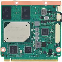
SOM-3569 - Unknown Advantech - Free user manual and instructions
Find the device manual for free SOM-3569 Advantech in PDF.


| Product Type | System on Module (SOM) |
| Dimensions | 82 mm x 50 mm |
| Weight | 50 g |
| Power Supply | 5 V DC, via carrier board |
| Power Consumption | 10 W (typical) |
| Processor | Intel Atom E3900 series |
| Memory | Up to 8 GB DDR4 |
| Storage | eMMC 5.1, up to 64 GB |
| Operating Temperature | -40°C to 85°C |
| Operating Systems Supported | Windows 10, Linux, Android |
| Main Functions | High-performance computing, multimedia, industrial IoT |
| Interfaces | HDMI, USB 3.0, Gigabit Ethernet, PCIe, I2C |
| Maintenance and Cleaning | Keep dry; clean with anti-static cloth; avoid solvents |
| Safety | ESD sensitive; handle with antistatic precautions |
| Spare Parts and Repairability | Non-serviceable; replace module if faulty |
| General Information | SMARC 2.1 compliant, designed for embedded systems |
Frequently Asked Questions - SOM-3569 Advantech
User questions about SOM-3569 Advantech
0 question about this device. Answer the ones you know or ask your own.
Ask a new question about this device
Download the instructions for your Unknown in PDF format for free! Find your manual SOM-3569 - Advantech and take your electronic device back in hand. On this page are published all the documents necessary for the use of your device. SOM-3569 by Advantech.
USER MANUAL SOM-3569 Advantech
natural_image
Illustration of four electronic circuit boards with white outlines on a purple background (no text or symbols)SOM-3569
Copyright
The documentation and the software included with this product are copyrighted 2018 by Advantech Co., Ltd. All rights are reserved. Advantech Co., Ltd. reserves the right to make improvements in the products described in this manual at any time without notice. No part of this manual may be reproduced, copied, translated or transmitted in any form or by any means without the prior written permission of Advantech Co., Ltd. Information provided in this manual is intended to be accurate and reliable. However, Advantech Co., Ltd. assumes no responsibility for its use, nor for any infringements of the rights of third parties, which may result from its use.
Acknowledgements
Intel and Pentium are trademarks of Intel Corporation.
Microsoft Windows and MS-DOS are registered trademarks of Microsoft Corp.
All other product names or trademarks are properties of their respective owners.
Product Warranty (2 years)
Advantech warrants to you, the original purchaser, that each of its products will be free from defects in materials and workmanship for two years from the date of purchase.
This warranty does not apply to any products which have been repaired or altered by persons other than repair personnel authorized by Advantech, or which have been subject to misuse, abuse, accident or improper installation. Advantech assumes no liability under the terms of this warranty as a consequence of such events.
Because of Advantech's high quality-control standards and rigorous testing, most of our customers never need to use our repair service. If an Advantech product is defective, it will be repaired or replaced at no charge during the warranty period. For out-of-warranty repairs, you will be billed according to the cost of replacement materials, service time and freight. Please consult your dealer for more details.
If you think you have a defective product, follow these steps:
-
Collect all the information about the problem encountered. (For example, CPU speed, Advantech products used, other hardware and software used, etc.) Note anything abnormal and list any onscreen messages you get when the problem occurs.
-
Call your dealer and describe the problem. Please have your manual, product, and any helpful information readily available.
-
If your product is diagnosed as defective, obtain an RMA (return merchandize authorization) number from your dealer. This allows us to process your return more quickly.
-
Carefully pack the defective product, a fully-completed Repair and Replacement Order Card and a photocopy proof of purchase date (such as your sales receipt) in a shippable container. A product returned without proof of the purchase date is not eligible for warranty service.
-
Write the RMA number visibly on the outside of the package and ship it prepaid to your dealer.
Part No. 2006356900 Edition 1
Printed in Taiwan May 2018
Declaration of Conformity
CE
This product has passed the CE test for environmental specifications. Test conditions for passing included the equipment being operated within an industrial enclosure. In order to protect the product from being damaged by ESD (Electrostatic Discharge) and EMI leakage, we strongly recommend the use of CE-compliant industrial enclosure products.
FCC Class B
Note: This equipment has been tested and found to comply with the limits for a Class B digital device, pursuant to part 15 of the FCC Rules. These limits are designed to provide reasonable protection against harmful interference in a residential installation. This equipment generates, uses and can radiate radio frequency energy and, if not installed and used in accordance with the instructions, may cause harmful interference to radio communications. However, there is no guarantee that interference will not occur in a particular installation. If this equipment does cause harmful interference to radio or television reception, which can be determined by turning the equipment off and on, the user is encouraged to try to correct the interference by one or more of the following measures:
■ Reorient or relocate the receiving antenna.
■ Increase the separation between the equipment and receiver.
■ Connect the equipment into an outlet on a circuit different from that to which the receiver is connected.
Consult the dealer or an experienced radio/TV technician for help.
FM
This equipment has passed the FM certification. According to the National Fire Protection Association, work sites are classified into different classes, divisions and groups, based on hazard considerations. This equipment is compliant with the specifications of Class I, Division 2, Groups A, B, C and D indoor hazards.
Technical Support and Assistance
- Visit the Advantech website at http://support.advantech.com where you can find the latest information about the product.
- Contact your distributor, sales representative, or Advantech's customer service center for technical support if you need additional assistance. Please have the following information ready before you call:
– Product name and serial number
– Description of your peripheral attachments
– Description of your software (operating system, version, application software, etc.)
– A complete description of the problem
– The exact wording of any error messages
Warnings, Cautions and Notes
Warning! Warnings indicate conditions, which if not observed, can cause personal injury!

Caution! Cautions are included to help you avoid damaging hardware or losing data. e.g.

There is a danger of a new battery exploding if it is incorrectly installed. Do not attempt to recharge, force open, or heat the battery. Replace the battery only with the same or equivalent type recommended by the manufacturer. Discard used batteries according to the manufacturer's instructions.
Note! Notes provide optional additional information.

Document Feedback
To assist us in making improvements to this manual, we would welcome comments and constructive criticism. Please send all such - in writing to: support@advantech.com
Packing List
Before setting up the system, check that the items listed below are included and in good condition. If any item does not accord with the table, please contact your dealer immediately.
■ SOM-3569 CPU module
■ 1 x Heatspreader (1960083260N001 or 1960083261N001)
Safety Instructions
- Read these safety instructions carefully.
- Keep this User Manual for later reference.
- Disconnect this equipment from any AC outlet before cleaning. Use a damp cloth. Do not use liquid or spray detergents for cleaning.
- For plug-in equipment, the power outlet socket must be located near the equipment and must be easily accessible.
- Keep this equipment away from humidity.
- Put this equipment on a reliable surface during installation. Dropping it or letting it fall may cause damage.
- The openings on the enclosure are for air convection. Protect the equipment from overheating. DO NOT COVER THE OPENINGS.
- Make sure the voltage of the power source is correct before connecting the equipment to the power outlet.
- Position the power cord so that people cannot step on it. Do not place anything over the power cord.
- All cautions and warnings on the equipment should be noted.
- If the equipment is not used for a long time, disconnect it from the power source to avoid damage by transient overvoltage.
- Never pour any liquid into an opening. This may cause fire or electrical shock.
- Never open the equipment. For safety reasons, the equipment should be opened only by qualified service personnel.
- If one of the following situations arises, get the equipment checked by service personnel:
■ The power cord or plug is damaged.
- Liquid has penetrated into the equipment.
■ The equipment has been exposed to moisture.
The equipment does not work well, or you cannot get it to work according to the user's manual.
■ The equipment has been dropped and damaged.
■ The equipment has obvious signs of breakage.
-
DO NOT LEAVE THIS EQUIPMENT IN AN ENVIRONMENT WHERE THE STORAGE TEMPERATURE MAY GO BELOW -20°C (-4°F) OR ABOVE 60°C (140°F). THIS COULD DAMAGE THE EQUIPMENT. THE EQUIPMENT SHOULD BE IN A CONTROLLED ENVIRONMENT.
-
CAUTION: DANGER OF EXPLOSION IF BATTERY IS INCORRECTLY REPLACED. REPLACE ONLY WITH THE SAME OR EQUIVALENT TYPE RECOMMENDED BY THE MANUFACTURER, DISCARD USED BATTERIES ACCORDING TO THE MANUFACTURER'S INSTRUCTIONS.
The sound pressure level at the operator's position according to IEC 704-1:1982 is no more than 70 dB (A).
DISCLAIMER: This set of instructions is given according to IEC 704-1. Advantech disclaims all responsibility for the accuracy of any statements contained herein.
Safety Precaution - Static Electricity
Follow these simple precautions to protect yourself from harm and the products from damage.
To avoid electrical shock, always disconnect the power from your PC chassis before you work on it. Don't touch any components on the CPU card or other cards while the PC is on.
- Disconnect power before making any configuration changes. The sudden rush of power as you connect a jumper or install a card may damage sensitive electronic components.
Chapter 1 General Information ....1
1.1 Introduction ...... 2
1.2 Functional Block Diagram 4
1.3 Product Specification 5
1.3.1 Compliance 5
1.3.2 Feature List 5
1.3.3 Processor System....6
1.3.4 Memory 6
1.3.5 Graphics / Audio 6
1.3.6 Expansion Interface 6
1.3.7 Serial Bus....6
1.3.8 I/O 7
1.3.9 Power Management....8
1.3.10 Environment....9
1.3.11 MTBF 9
1.3.12 OS Support (duplicate with SW chapter) 9
1.3.13 Advantech iManager 9
1.3.14 Power Consumption.... 10
1.3.15 Performance ...... 10
1.3.16 Selection Guide w/ P/N 11
1.3.17 Packing list.... 11
1.3.18 Development Board 11
1.3.19 Optional Accessory 11
1.3.20 Pin Description.... 11
Chapter 2 Mechanical Information ....13
2.1 Board Information.... 14
Figure 2.1 Board chips identify - Front.... 14
Figure 2.2 Board chips identify - Rear 14
2.2 Mechanical Drawing.... 15
Figure 2.3 Board Mechanical Drawing - Front 15
Figure 2.4 Board Mechanical Drawing - Rear.... 15
Figure 2.5 Board Mechanical Drawing - Side 16
2.3 Assembly Drawing 17
Figure 2.6 Assembly Drawing.... 17
2.4 CPU Mechanical Drawing 18
Figure 2.7 Main Chip Height and Tolerance 18
Figure 2.8 Main Chip Height and Tolerance 18
Chapter 3 AMI BIOS....19
3.1 Introduction 20
Figure 3.1 Setup program initial screen.... 20
3.2 Entering Setup 21
3.3 Main Setup 21
Figure 3.2 Main setup screen 21
3.4 Advanced BIOS Features Setup 22
Figure 3.3 Advanced BIOS features setup screen 22
3.4.1 Trusted Computing 23
Figure 3.4 Trusted Computing 23
3.4.2 ACPI Settings.... 24
Figure 3.5 ACPI Settings 24
3.4.3 Embedded Controller 25
Figure 3.6 Embedded Controller.... 25
Figure 3.7 Serial Port 1 Configuration 26
Figure 3.8 Serial Port 2 Configuration 27
Figure 3.9 Hardware Monitor....28
3.4.4 Serial Port Console Redirection.... 28
Figure 3.10 Serial Port console Redirection ...... 28
3.4.5 CPU Configuration.... 30
Figure 3.11CPU Configuration 30
Figure 3.12Socket 0 CPU Information.... 31
Figure 3.13CPU Power Management.... 32
3.4.6 Network Stack Configuration 33
Figure 3.14 Network Stack Configuration.... 33
3.4.7 CSM Configuration 34
Figure 3.15CSM Configuration 34
3.4.8 NVMe Configuration 35
Figure 3.16NVMe Configuration 35
3.4.9 SDIO Configuration.... 35
Figure 3.17SDIO Configuration 35
3.4.10 USB Configuration 36
Figure 3.18USB Configuration.... 36
3.4.11 Platform Trust Technology.... 37
Figure 3.19 Platform Trust Technology 37
3.4.12 Security Configuration 38
Figure 3.20Security Configuration 38
3.5 Chipset Setup 39
Figure 3.21 Chipset Setup.... 39
3.5.1 North Bridge 40
Figure 3.22 North Bridge 40
3.5.2 South Bridge 41
Figure 3.23South Bridge.... 41
3.5.3 Uncore Configuration.... 42
Figure 3.24Uncore Configuration 42
3.5.4 South Cluster Configuration.... 43
Figure 3.25South Cluster Configuration 43
Figure 3.26HD-Audio Configuration 44
Figure 3.27PCI Express Configuration 45
Figure 3.28LAN 46
Figure 3.29PCI Express Root Port 0 47
Figure 3.30PCI Express Root Port 1 48
Figure 3.31PCI Express Root Port 2 49
Figure 3.32PCI Express Root Port 3 50
Figure 3.33SATA Drives.... 51
Figure 3.34SCC Configuration 52
Figure 3.35USB Configuration.... 53
Figure 3.36 Miscellaneous Configuration 54
3.6 Security Chipset 55
Figure 3.37Security Chipset 55
3.7 Boot Setup 56
Figure 3.38Boot Setup.... 56
3.8 Save & Exit 57
Figure 3.39Save & Exit....57
Chapter 4 S/W Introduction & Installation...... 59
4.1 S/W Introduction 60
4.2 Driver Installation 60
4.2.1 Windows Driver Setup 60
4.2.2 Other OS....60
4.3 Advantech iManager 60
Appendix A Pin Assignment....63
A.1 SOM-3569 Qseven R2.1 Pin Assignment.... 64
Appendix B Watchdog Timer 67
B.1 Programming the Watchdog Timer 68
Appendix C System Assignments ......69
C.1 System I/O Ports 70
C.2 Interrupt Assignments 72
C.3 1st MB Memory Map 73
Chapter 1
General Information
This chapter gives background information on the SOM-3569 CPU Computer on Module
Sections include:
Introduction
Functional Block Diagram
Product Specification
1.1 Introduction
SOM-3569 is equipped with Intel Atom®processor E3900 series, Celeron® & Pentium®N series platform, which are manufactured on Intel 14nm process technology. SOM-3569 non-ECC memory supports LPDDR4 2400MT/s with 1.2V power design, and up to 8GB dual channel. SOM-3569 is able to support 4 PCIex1 with Gen2 technology, as well as PCIe x1, x2, x4 configurations if requested. Most importantly, SOM-3569 adopts a 13.2mm heatsink passive thermal solution and supports CPU TDP up to 12 watt at 60°C ambient (option accessory) temp. This is suitable for multiple I/O designs for high performance applications, such as for in mobile, automation, HMI equipment, and control monitoring fields.
SOM-3569 offers over 30% growth in processor performance over previous platforms. It supports DX12, OpenGL 4.3, OGL ES 3.0, and OpenCL 2.0. In addition, dual displays are supported, as is HDMI/DisplayPort with 4K2K resolution, and dual channel LVDS at 1920x1200 full HD resolution is also available.
Advantech iManager & WISE-PaaS/RMM is designed to satisfy a lot of embedded application requirements such as multi-level watchdog timer, voltage and temperature monitoring, thermal protection and mitigation through processor throttling, LCD backlight on/off and brightness control, embedded storage for customized information, and more. Combining Advantech WISE-PaaS/RMM, it can remotely monitor and control devices through the internet. All Advantech Qseven modules integrate iManager and WISE-PaaS/RMM to benefit customer's applications.
With extreme performance, embedded platform power consumption, and various extensions and I/O interfaces, SOM-3569 is suitable for computing intensive designs, thermal sensitive designs, graphics/media sensitive designs, and all I/O demanding applications.
Acronyms
| Term Define | |
| AC'97 Audio CODEC (Coder-Decoder) | |
| ACPI | Advanced Configuration Power Interface – standard to implement power saving modes in PC-AT systems |
| BIOS | Basic Input Output System – firmware in PC-AT system that is used to initialize system components before handing control over to the operating system |
| CAN | Controller-area network (CAN or CAN-bus) is a vehicle bus standard designed to allow micro controllers to communicate with each other within a vehicle without a host computer |
| DDI Digital Display Interface – containing DisplayPort, HDMI/DVI, and SDVO | |
| EAPI | Embedded Application Programmable InterfaceSoftware interface for COM Express® specific industrial functionSystem informationWatchdog timerI2C BusFlat Panel brightness controlUser storage areaGPIO |
| GbE Gigabit Ethernet | |
| HDA | Intel High Definition Audio (HD Audio) refers to the specification released by Intel in 2004 for delivering high definition audio that is capable of playing back more channels at higher quality than AC'97 |
| I2C | Inter Integrated Circuit – 2 wire (clock and data) signaling scheme allowing communication between integrated circuit, primarily used to read and load register values |
| ME Management Engine | |
| PC-AT | "Personal Computer – Advanced Technology" – an IBM trademark term used to refer to Intel based personal computer in 1990s |
| PEG PCI Express Graphics | |
| RTC | Real Time Clock – battery backed circuit in PC-AT systems that keeps system time and date as well as certain system setup parameters |
| SPD | Serial Presence Detect – refers to serial EEPROM on DRAMs that has DRAM Module configuration information |
| TPM | Trusted Platform Module – chip to enhance the security features of a computer system |
| UEFI Unified Extensible Firmware Interface | |
| WDT Watch Dog Timer | |
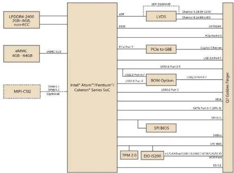
1.2 Functional Block Diagram
Block Diagram
flowchart
graph TD
    A["LPDDR4-2400 2GB~8GB, non-ECC"] --> B["Intel® Atom™/Pentium™/ Celeron® Series SoC"]
    C["eMMC 4GB-64GB"] --> D["Optical"]
    E["MIP1-CSI2"] --> F["Optical"]
    B --> G["LVDS"]
    B --> H["BOM Option"]
    H --> I["SPI BIOS"]
    H --> J["TPM 2.0"]
    H --> K["EIO-IS200"]
    G --> L["Channel A 24-bit LVDS"]
    G --> M["Channel B 24-bit LVDS"]
    H --> N["USB2.0 Port 0-7"]
    H --> O["USB3.0 Port 1"]
    H --> P["SATA Port 0.1 (SPX 3)"]
    H --> Q["SPI BUS"]
    H --> R["SMBus"]
    H --> S["LPC BUS"]
    H --> T["SD 3.0"]
    L --> U["PCIe to GBE"]
    M --> V["Gusbit Ethernet"]
    N --> W["USB 3.0 Port 1"]
    O --> X["USB2.0 Port 0-7"]
    P --> Y["USB3.0 Port 1"]
    Q --> Z["SATA Port 0.1 (SPX 3)"]
    R --> AA["SMBus"]
    S --> AB["LPC BUS"]
    T --> AC["SD 3.0"]
1.3 Product Specification
1.3.1 Compliance
PICMG Seven Revision 2.1
■ Basic Size - 70 x707mm
■ Pin-out Seven R2.1 compatible
1.3.2 Feature List
| Seven Features R2.1 SOM-3569 | ||||
| System I/O Interface | x86 Based Mini-mum Configura-tion | Maximum Con-figuration | Default Option | |
| PCI Express Lanes 1 (x1 link) 4 4 - | ||||
| Serial ATA Channels 0 2 2 - | ||||
| USB2.0 ports 4 8 6 8 | ||||
| USB3.0 ports 0 3 2 1 | ||||
| LVDS channels/embedded DisplayPort | 00 | Dual Channel24-bit2 | Dual Cannel24-bit0 | 01 |
| DisplayPort/TMDS | 0 | 1 | 1 | - |
| HD Audio/AC'97/I2S | 0 1 1 (HD Audio) | - | ||
| Ethernet (10/100/Giga-bit) | 0 | 1 (Gigabit Ethernet) | 1 | - |
| UART | 0 1 1 2 | |||
| LPC | 0 1 1 - | |||
| SDIO 4-bit for SD/MMC Card | 0 1 1 (4-bit) | - | ||
| SMBus | 1 1 1 - | |||
| I2C Bus | 1 1 1 - | |||
| SPI Bus | 0 1 1 - | |||
| CAN Bus | 0 1 1 - | |||
| Watchdog Trigger | 1 1 1 - | |||
| Power Button | 1 1 1 - | |||
| Power Good | 1 1 1 - | |||
| Reset Button | 1 1 1 - | |||
| LID Button | 0 1 1 - | |||
| Sleep Button | 0 1 1 - | |||
| Suspend to RAM (S3 mode) | 0 | 1 | 1 | - |
| Wake | 0 | 1 | 1 - | |
| Battery Low Alarm | 0 1 1 - | |||
| Thermal Control | 0 1 1 - | |||
| FAN Control | 0 1 1 - | |||
1.3.3 Processor System
| CPU Std. Free. | Max. Turbo Free. | Core | Cache (MB) | TDP(W) |
| Pentium N4200 | 1.1GHz 2.5GHz 4 2 6 | |||
| Celeron N3350 | 1.1GHz 2.4GHz 2 2 6 | |||
| Atom X7-E3950 | 1.6GHz 2.0GHz 4 2 12 | |||
| Atom X5-E3940 | 1.6GHz 1.8GHz 4 2 9 | |||
| Atom X5-E3930 | 1.3GHz 1.8GHz 2 2 6 |
1.3.4 Memory
Dual channels onboard LPDDR4 2400MHz up to 8GB (non-ECC).
1.3.5 Graphics / Audio
Graphic Core: Intelligent 9.0 LP Graphic supports DX9.3/10/11.3/12; OpenGL 4.3; OGL ES 3.0; OpenCL 2.0, HEVC/H265, VC1/WMV9 HW decode/encode acceleration.
| CPU Graphic Core Base Free. | Max Free. | ||
| Pentium N4200 Gen9 HD Graphic | 200MHz | 750MHz | |
| Celeron N3350 | Gen9 HD Graphic | 200MHz | 650MHz |
| Atom X7-E3950 | Gen9 HD Graphic | 500MHz | 650MHz |
| Atom X5-E3940 | Gen9 HD Graphic | 400MHz | 600MHz |
| Atom X5-E3930 | Gen9 HD Graphic | 400MHz | 550MHz |
1.3.6 Expansion Interface
1.3.6.1 PCIe x1
PCI Express x1: Supports default 4 ports PCIe x1 compliant to PCIe Gen2 (5.0 GT/s) specification, configurable to PCIe x4 or PCIe x2 upon request. Several configurable combinations may need BIOS modifications. Please contact Advantech sales or FAE for more details.
| So | P0 | P1 | P2 | P3 | P4 | P5 |
| Default | X1 | X1 | X1 | X1 | GBE | |
| Option | X4 | GBE | ||||
| Other 1 | X2 | X2 | GBE | |||
| Other 2 | X2 | X1 | X1 | GBE | ||
1.3.6.2 LPC
Supports Low Pin Count (LPC) 1.1 specification, without DMA or bus mastering. Allows connection to Super I/O, embedded controller, or TPM. LPC clock is 25MHz.
1.3.7 Serial Bus
1.3.7.1 SMBus
Supports SMBus 2.0 specification.
1.3.7.2 I2C Bus
Supports I2C bus 7-bit and 10-bit address modes, up to 400KHz.
1.3.8 I/O
1.3.8.1 Gigabit Ethernet
Ethernet: Intel I211AT Gigabit LAN supports 100/1000 Mbps Speed.
1.3.8.2 SATA
Support 2 ports SATA Gen3 (6.0 Gb/s), backward compliant to SATA Gen2 (3.0 Gb/s) and Gen1 (1.5 Gb/s). Maximum data rate is 600 MB/s. Supports AHCI 1.3.1 mode.
1.3.8.3 USB3.0/USB2.0
1 ports USB3.0 (5.0 Gaps) and 8 ports USB2.0 (480 Mbps) which are backward compatible to USB1.x.
1.3.8.4 USB3.0
| Seven P0 P1 | ||
| So P0 P1 | ||
| Schematics USB_0_1_OC | ||
| SoC USB_OC# OC0# | ||
1.3.8.5 USB2.0
| Qseven P0 P1 P2 | P3 | P4 | |||
| SoC | P0 P1 P2 P3 | P4 | |||
| Schematics | USB_0_1_OC | USB_2_3_OC | USB_4_5_OC | ||
| SoC USB_OC# | OC0# OC1# | ||||
1.3.8.6 HDA
Supports HD-Audio and LPE Audio for DDI[1:0] (DisplayPort and HDMI), 1.8V signal level, up to 24 MHz serial data clock.
1.3.8.7 SPI Bus
Supports Master SPI operation only. SPI clock can be 50MHz, 33MHz, or 20MHz, capacity up to 16MB.
1.3.8.8 eMMC
eMMC v5.0 HS400 DDR Mode. Supports transfer the data in 1-bit, 4-bit, and 8-bit modes. Maximum HS400 Dual Rate 400 MB/s (200 MHz).
1.3.8.9 SD
SD Memory Card Specification v3.01. SD clock frequency at 25, 50, 100, and 200 MHz. Data Rate up to 104 MB/s using 4 parallel data lines (SDR104 mode).
1.3.8.10 SDIO
Supports one SDIO 3.0 interface
1.3.8.11 TXE
Trusted Execution Engine 3.0 (TXE3.0).
1.3.8.12 SMBus
SMBus 2.0 specification. Supports SMBALERT# signal. Signal level 3.3V or 1.8V selectable.
1.3.8.13 Serial port
2 ports 4-wire HSUART signal interface using RTS/CTS control only
■ Programmable FIFO enable/disable
■ 64B iDMA FIFO per channel with up to 32B burst capability
■ Even, odd, or no parity bit selectable
■ 1, 1.5, or 2 stop bit selectable
1.3.8.14 MIPI
Supports CSI2 image sensors connected using both D-PHY 1.1 and D-PHY 1.2. SoC has 4 dedicated DPHY1.2 lanes and 2 differential clock lanes, supporting peak transfer rates of 2.5Gb/s per lane.
1.3.8.15 TPM
Supports TPM 2.0 module by default.
1.3.8.16 BIOS
BIOS chip is on module by default. Also allows users to place a BIOS chip on the carrier board with appropriate design and a pull-down to GND on BIOS_DISABLE# pin.
Note! If the system COMS is cleared, we strongly suggest to go to the BIOS setup menu and load default settings on first boot up.

1.3.9 Power Management
1.3.9.1 Power Supply
Supports both ATX and AT power modes. VSB is for suspend power and can be option if not require standby (suspend-to-RAM) support. RTC Battery may be option if keep time/date is not require.
VCC: 5V +/- 5%
■ VSB: 5V +/- 5% (Suspend power)
■ RTC Battery Power: 2.0V - 3.3V
1.3.9.2 PWROK
Power OK from main power supply. A high value indicates that the power is good. This signal can be used to hold off Module startup to allow Carrier based FPGAs or other configurable devices time to be programmed.
1.3.9.3 Power Sequence
Refer to Qseven R2.1 electrical specification
1.3.9.4 Wake Event
Various wake-up events supporting allow user to apply into different scenario.
Wake-on-LAN(WOL): Wake to S0 from S3/S4/S5
USB Wake: Wake to S0 from S3
PCIe Device Wake: depends on user inquiry and may need customized BIOS
LPC Wake: depends on user inquiry and may need customized BIOS
1.3.9.5 Advantech S5 ECO Mode (Deep Sleep Mode)
Advantech iManager provides additional feature to allow system enter a very low suspend power mode - S5 ECO mode. In this mode, Module will cut all power including suspend and active power into chipset and keep an on-module controller active. Therefore, only an under 50mW power will consume which means user's battery pack can last longer time. While this mode enable in BIOS, system (or module) only allow a power button to boot rather than others such as WOL.
1.3.10 Environment
1.3.10.1 Temperature
Operating: 0 \~ 60°C (32 \~ 140°F), Storage: -40°C \~ 85°C (-40 \~ 185°F)
Extended temperature support: -40\~85°C(-40 \~ 185°F)
1.3.10.2 Humidity
Operating: 40°C@95% relative humidity, non-condensing
Storage: 60°C@95% relative humidity, non-condensing
1.3.10.3 Vibrations
3.5G, 5\~500Hz X/Y/Z Axis
1.3.10.4 Drop Test (Shock)
Federal Standard 101 Method 5007 test procedure with standard packing
1.3.10.5 EMC
CE EN55022 Class B and FCC Certifications: validate with standard development boards in Advantech chassis
1.3.11 MTBF
Please refer Advantech SOM-3569 Series Reliability Prediction Report No: TBD. (estimated date is 2018, January.)
1.3.12 OS Support (duplicate with SW chapter)
The mission of Advantech Embedded Software Services is to "Enhance quality of life with Advantech platforms and Microsoft Windows embedded technology." We enable Windows Embedded software products on Advantech platforms to more effectively support the embedded computing community. Customers are freed from the hassle of dealing with multiple vendors (Hardware suppliers, System integrators, Embedded OS distributor) for projects. Our goal is to make Windows Embedded Software solutions easily and widely available to the embedded computing community.
To install the drivers, please connect to internet and browse the website http://support.advantech.com.tw to download the setup file.
1.3.13 Advantech iManager
Support APIs for GPIO, smart fan control, multi-stage watchdog timer and output, temperature sensor, hardware monitor, etc. Follow by PICMG EAPI 1.0 specification that provides backward compatibility.
1.3.14 Power Consumption
| Power Consumption Table (Watt.) | ||||||
| VCC=12V, VSB=5V Active Power Domain Suspend Power Domain | Mechanical off | |||||
| Power State S0 Max. Load S0 Burn-in S0 Idle S5 S5 Deep Sleep RTC (uA) | ||||||
| SOM-3569CN0C-S2A1 | 8.22W | 5.89W | 3.71W | 0.73W | - | - |
Hardware Configurations:
- MB: SOM-3569CN0C-S2A1 (PCB_A101-2)
- DRAM: 8Gb LPDDR4 2400MHz *4 (4GB)
- Carrier board: SOM-DB3520-00A1E
Test Condition:
- Test temperature: room temperature (about 25°C)
- Test voltage: rated voltage DC +12.0V
- Test loading:
3.1 Maximum load mode: According to Intel thermal/power test tools
3.2 Burn-in mode: Burn-In Test V8.1 Pro(1013)(CPU, RAM, 2D&3D Graphics and Disk
with 100%)
3.3 Idle mode: DUT power management off and no running any program.
4. OS: Windows 10 Enterprise
1.3.15 Performance
For reference performance or benchmark data that compare with other module, please refer to "Advantech COM Performance & Power Consumption Table".
1.3.16 Selection Guide w/ P/N
| Part No. | CPU | Freq. | Core | CPU TDP | Memory | eMMC | Thermal Solution | Operating Temperature |
| SOM-3569CNOC-S2A1 | Pentium N4200 | 1.1GHz | 4C | 6W | 4GB | N/A | Passive | 0 ~ 60 °C |
| SOM-3569CNOC-S1A1 | Celeron N3350 | 1.1GHz | 2C | 6W | 4GB | N/A | Passive | 0 ~ 60 °C |
| SOM-3569CNBC-S7A1 | Atom E3950 | 1.6GHz | 4C | 12W | 4GB | 32GB | Passive | 0 ~ 60 °C |
| SOM-3569CNOC-S6A1 | Atom E3940 | 1.6GHz | 4C | 9W | 4GB | N/A | Passive | 0 ~ 60 °C |
| SOM-3569CNOC-S3A1 | Atom E3930 | 1.3GHz | 2C | 6W | 4GB | N/A | Passive | 0 ~ 60 °C |
1.3.17 Packing list
| Part No. | Description | Quantity |
| - | SOM-3569 Qseven CPU Module | 1 |
| 1960083260N001 | SOM-3569 non-I-APL Heatspreader (N4200 & N3350) | 1 |
| 1960083261N001 | SOM-3569 I-APL Heatspreader (E3930, E3940 & E3950) | 1 |
1.3.18 Development Board
| Part No. | Description |
| SOM-DB3520-00A1E | Qseven Development Board |
1.3.19 Optional Accessory
| Part No. | Description |
| 1960058145N001 | Semi-Heatsink, 70L x 63W x 13.2H (0 ~ 60 °C) |
| 1960061089N001 | Semi-Heatsink, 70L x 63W x 34H (-40 ~ 85 °C) |
1.3.20 Pin Description
Advantech provides useful checklists for schematic design and layout routing. A schematic checklist will specify details about each pin's electrical properties and how to connect for different applications. The layout checklist will specify the layout constraints and recommendations for trace length, impedance, and other necessary information during design and development. Please contact your nearest Advantech branch office or call to request design documents and further advanced support.
Chapter 2
Mechanical Information
This chapter gives mechanical information on the SOM-3569 CPU Computer on Module
Sections include:
Board Information
Mechanical Drawing
Assembly Drawing
2.1 Board Information
The figures below indicate the main chips on SOM-3569 Computer-on-Module. Be aware of these positions while designing a carrier board to avoid mechanical and thermal issues for the best thermal dispassion performance.

Figure 2.1 Board chips identify - Front
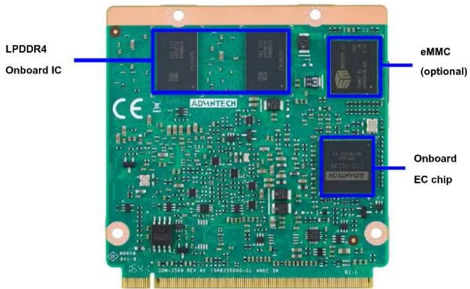
Figure 2.2 Board chips identify - Rear
2.2 Mechanical Drawing
For more details about 2D/3D models, please look on the Advantech COM support service website http://com.advantech.com.

Figure 2.3 Board Mechanical Drawing - Front
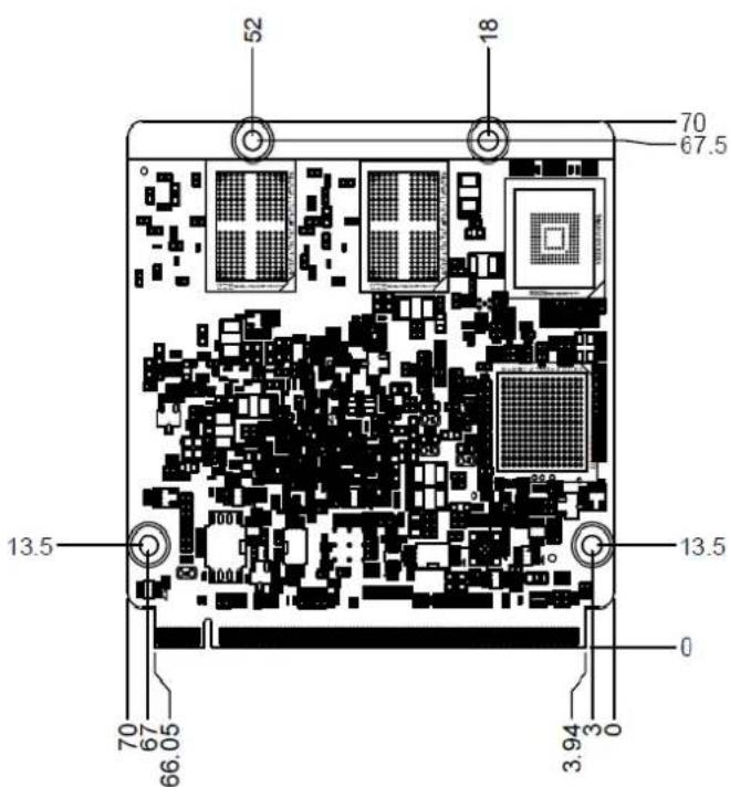
Figure 2.4 Board Mechanical Drawing - Rear
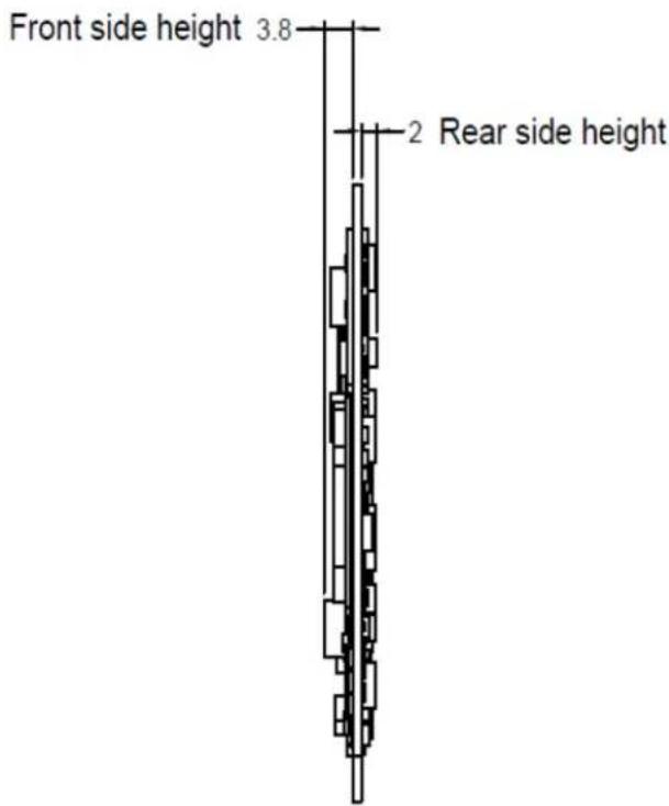
Figure 2.5 Board Mechanical Drawing - Side
2.3 Assembly Drawing
These figures demonstrate the assembly order from the thermal module and COM module to the carrier board.

natural_image
Technical line drawing of an electronic circuit board with cooling fans and internal components (no text or symbols)Figure 2.6 Assembly Drawing
There are 4 reserved screw holes for SOM-3569 to be pre-assembled with the heat spreader.
2.4 CPU Mechanical Drawing
Carefully consider the CPU and chip height tolerance when designing your thermal solution.
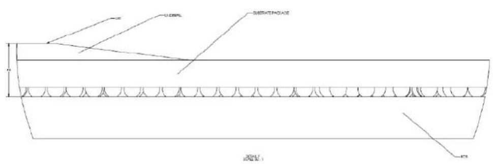
Intel® Pentium and Celeron N and J Series Processors
Figure 2.7 Main Chip Height and Tolerance

Intel® Pentium and Celeron N and J Series Processors
Figure 2.8 Main Chip Height and Tolerance
Chapter 3
AMI BIOS
This chapter gives BIOS setup information for the SOM-3569 CPU computer-on module
Sections include:
Introduction
Entering Setup
Hot/Operation Key
■ Exit BIOS Setup Utility
3.1 Introduction
AMI BIOS has been integrated into many motherboards for over a decade. With the AMI BIOS Setup Utility, users can modify BIOS settings and control various system features. This chapter describes the basic navigation of the BIOS Setup Utility.
![Aptio Setup Utility - Copyright (C) 2017 American Megatrends, Inc. Main Advanced Chipset Security Boot Save & Exit BIOS Information BIOS Vendor American Megatrends Core Version 5.0.1.2 0.28 x64 Compliance UEFI 2.5.0; PI 1.4 Project Version SOM 35690000060X021 Build Date and Time 10/23/2017 16:20:55 Access Level Administrator Memory Information Total Memory 2048 MB Memory Speed 2400 MHz System Date [Thu 10/26/2017] System Time [15:48:40] Set the Date. Use Tab to switch between Date elements. Default Ranges: Year: 2005-2099 Months: 1-12 Days: dependent on month +: Select Screen ↑↓: Select Item Enter: Select +/-: Change Opt. F1: General Help F2: Previous Values F3: Optimized Defaults F4: Save & Exit ESC: Exit Version 2.10.1263. Copyright (C) 2017 American Megatrends, Inc.](/content/2026/06/1246723/images/67983b7ef2bd54dcca3f80d36f6fb5bd93d5521e3bfccbe1ea52e6d70ebfeaa3.jpg)
Figure 3.1 Setup program initial screen
AMI's BIOS ROM has a built-in Setup program that allows users to modify the basic system configuration. This information is stored in flash ROM so it retains the Setup information when the power is turned off.
3.2 Entering Setup
Turn on the computer and then press or
3.3 Main Setup
When users first enter the BIOS Setup Utility, users will enter the Main setup screen. Users can always return to the Main setup screen by selecting the Main tab. There are two Main Setup options. They are described in this section. The Main BIOS Setup screen is shown below.
![Aptio Setup Utility - Copyright (C) 2017 American Megatrends, Inc. Main Advanced Chipset Security Boot Save & Exit BIOS Information BIOS Vendor American Megatrends Core Version 5.0.1.2 0.28 x64 Compliancy UEFI 2.5.0; PI 1.4 Project Version SCM 35690000060X021 Build Date and Time 10/23/2017 16:20:55 Access Level Administrator Memory Information Total Memory 2048 MB Memory Speed 2400 MHz System Date [Thu 10/26/2017] System Time [15:48:40] Set the Date. Use Tab to switch between Date elements. Default Ranges: Year: 2005-2099 Months: 1-12 Days: dependent on month +: Select Screen ↑↓: Select Item Enter: Select +/-: Change Opt. F1: General Help F2: Previous Values F3: Optimized Defaults F4: Save & Exit ESC: Exit Version 2.18.1263. Copyright (C) 2017 American Megatrends, Inc.](/content/2026/06/1246723/images/b24491c7102a9af81fbfd5c22deedb7a6d2e5fca38406dc6e1d53974c4f3435e.jpg)
Figure 3.2 Main setup screen
The Main BIOS setup screen has two main frames. The left frame displays all the options that can be configured. Grayed-out options cannot be configured; options in blue can. The right frame displays the key legend.
Above the key legend is an area reserved for a text message. When an option is selected in the left frame, it is highlighted in white. Often a text message will accompany it.
System time / System date
Use this option to change the system time and date. Highlight System Time or System Date using the
3.4 Advanced BIOS Features Setup
Select the Advanced tab from the SOM-3569 setup screen to enter the Advanced BIOS Setup screen. Users can select any item in the left frame of the screen, such as CPU Configuration, to go to the sub menu for that item. Users can display an Advanced BIOS Setup option by highlighting it using the

Figure 3.3 Advanced BIOS features setup screen
Trusted Computing
Trusted Computing Settings
ACPI Settings
System ACPI Parameters
Embedded Controller
Embedded Controller Parameters
Serial Port Console Redirection
Serial Port Console Redirection
CPU Configuration
CPU Configuration Parameters
Network Stack Configuration
Network Stack Settings
CSM Configuration
CSM configuration: Enable/Disable, Option ROM execution settings, etc.
NVMe Configuration
NVMe Device Options Settings
SDIO Configuration
SDIO Configuration Parameters
USB Configuration
USB Configuration Parameters
Platform Trust Technology
Platform Trust Technology
Security Configuration
Intel(R) Anti-Theft Technology Configuration
3.4.1 Trusted Computing
![Aptio Setup Utility - Copyright (C) 2017 American Megatrends, Inc. Advanced Configuration Security Device Support [Disable] NO Security Device Found Enables or Disables BIOS support for security device. O.S. will not show Security Device. TCG EFI protocol and INT1A interface will not be available. ++: Select Screen ↑↓: Select Item Enter: Select +/-: Change Opt. F1: General Help F2: Previous Values F3: Optimized Defaults F4: Save & Exit ESC: Exit Version 2.18.1263. Copyright (C) 2017 American Megatrends, Inc.](/content/2026/06/1246723/images/5dbe0802ef1db7a929c2fec83484b19afcc1cb1cfb4e5d32f7bf7939329d94e7.jpg)
Figure 3.4 Trusted Computing
Security Device Support
Enables or Disables BIOS support for security device. The OS will not show Security Device. TCG EFI protocol and INT1A interface will not be available.
3.4.2 ACPI Settings
![Aptio Setup Utility - Copyright (C) 2017 American Megatrends, Inc. Advanced ACPI Settings Enable ACPI Auto Configuration [Disabled] Enable Hibernation [Enabled] ACPI Sleep State [S3 (Suspend to RAM)] Lock Legacy Resources [Disabled] Enables or Disables BIOS ACPI Auto Configuration. ++: Select Screen 11: Select Item Enter: Select +/-: Change Opt. F1: General Help F2: Previous Values F3: Optimized Defaults F4: Save & Exit ESC: Exit Version 2.18.1263. Copyright (C) 2017 American Megatrends, Inc.](/content/2026/06/1246723/images/7b534a5e8db4a72982b73f774c80b65766d9630b14dbbd1f15d8882413fb3579.jpg)
Figure 3.5 ACPI Settings
Enable ACPI Auto Configuration
Enables or Disables BIOS ACPI Auto Configuration.
Enable Hibernation
Enables or Disables System ability to Hibernate (OS/S4 Sleep State). This option may be not effective with some OS.
ACPI Sleep State
Select the highest ACPI sleep state the system will enter when the SUSPEND button is pressed.
Lock Legacy Resources
Enables or Disables Lock of Legacy Resources
3.4.3 Embedded Controller
![Aptio Setup Utility - Copyright (C) 2017 American Megatrends, Inc. Advanced Embedded Controller Embedded Controller EIO-IS200 Firmware Version V01060266 CPU Shutdown Temperature [Disable] Smart Fan - Carrier Board [Auto] Backlight Enable Polarity [Native] Brightness PWM Polarity [Native] Power Saving Mode [Normal] Serial Port 1 Configuration Serial Port 2 Configuration Hardware Monitor CPU Shutdown Temperature +: Select Screen ↑↓: Select Item Enter: Select +/-: Change Opt. F1: General Help F2: Previous Values F3: Optimized Defaults F4: Save & Exit ESC: Exit Version 2.18.1263. Copyright (C) 2017 American Megatrends, Inc.](/content/2026/06/1246723/images/0227aa07bfa8631ddbba88525c57fe9297c7df0751e5841dead069f39b814aa0.jpg)
Figure 3.6 Embedded Controller
CPU Shutdown Temperature
CPU Shutdown Temperature
Smart Fan - Carrier Board
Control Carrier Board Smart FAN function. Get value from EC and only set value when Save Changes.
Backlight Enable Polarity
Switch Backlight Enable Polarity for Native or Invert
Brightness PWM Polarity
Backlight Control Brightness PWM Polarity for Native or Invert
Power Saving Mode
Select Power Saving Mode
Serial Port 1 Configuration
Set Parameters of Serial Port 1 (COMA)
Serial Port 2 Configuration
Set Parameters of Serial Port 2 (COMB)
Hardware Monitor
Monitor hardware status
3.4.3.1 Serial Port 1 Configuration
![Aptio Setup Utility - Copyright (C) 2017 American Megatrends, Inc. Advanced Serial Port 1 Configuration Serial Port [Enabled] Device Settings IC=3F8h; IRQ=4; Change Settings [Auto] Enable or Disable Serial Port (COM) +: Select Screen ↑↓: Select Item Enter: Select +/-: Change Opt. F1: General Help F2: Previous Values F3: Optimized Defaults F4: Save & Exit ESC: Exit Version 2.18.1263. Copyright (C) 2017 American Megatrends, Inc.](/content/2026/06/1246723/images/b9956ae5fe5de0036f3b3f6ea0329247c036efa61c85ef9e1e0f5324ad5faa5d.jpg)
Figure 3.7 Serial Port 1 Configuration
Serial Port
Enable or Disable Serial Port (COM)
Device Settings
Set Parameters of Serial Port 1 (COMA)
Change Settings
Select an optimal settings for Super IO Device
3.4.3.2 Serial Port 2 Configuration
![Aptio Setup Utility - Copyright (C) 2017 American Megatrends, Inc. Advanced Serial Port 2 Configuration Serial Port [Enabled] Device Settings IO=2F3h; IRQ=3; Change Settings [Auto] Enable or Disable Serial Port (COM) +: Select Screen ↓: Select Item Enter: Select +/-: Change Opt. F1: General Help F2: Previous Values F3: Optimized Defaults F4: Save & Exit ESC: Exit Version 2.18.1263. Copyright (C) 2017 American Megatrends, Inc.](/content/2026/06/1246723/images/b192f893cd74fcaef215c0ce1aa5e3d0acb563e8a005fc7a6a1393a55f012fdf.jpg)
Figure 3.8 Serial Port 2 Configuration
Serial Port
Enable or Disable Serial Port (COM)
Device Settings
Set Parameters of Serial Port 2 (COMB)
Change Settings
Select an optimal settings for Super IO Device
3.4.3.3 Hardware Monitor
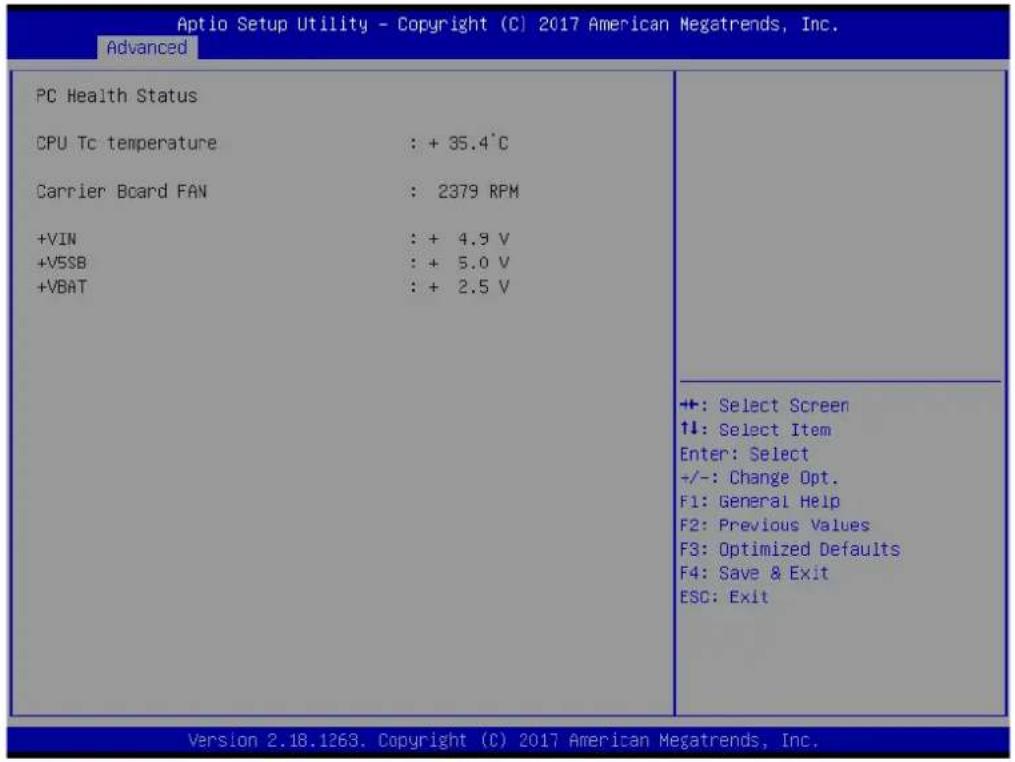
Figure 3.9 Hardware Monitor
3.4.4 Serial Port Console Redirection
![Aptio Setup Utility - Copyright (C) 2017 American Megatrends, Inc. Advanced COM1 Console Redirection [Disabled] ► Console Redirection Settings COM2 Console Redirection [Disabled] ► Console Redirection Settings Legacy Console Redirection ► Legacy Console Redirection Settings Serial Port for Out-of-Band Management/ Windows Emergency Management Services (EMS) Console Redirection [Disabled] ► Console Redirection Settings Console Redirection Enable or Disable. ++: Select Screen 11: Select Item Enter: Select +/-: Change Opt. F1: General Help F2: Previous Values F3: Optimized Defaults F4: Save & Exit ESC: Exit Version 2.18.1263. Copyright (C) 2017 American Megatrends, Inc.](/content/2026/06/1246723/images/58547e72b18ba9b9ce41b0e9540ee0281d13c91c51b8fe8cc5fa20285ffba5b1.jpg)
Figure 3.10 Serial Port console Redirection
COM1
Console Redirection
Console Redirection Enable or Disable.
Console Redirection Settings
The settings specify how the host computer and the remote computer (which the user is using) will exchange data. Both computers should have the same or compatible settings.
COM2
Console Redirection
Console Redirection Enable or Disable.
Console Redirection Settings
The settings specify how the host computer and the remote computer (which the user is using) will exchange data. Both computers should have the same or compatible settings.
Legacy Console Redirection
Legacy Console Redirection Settings
Legacy Console Redirection Settings
Serial Port for Out-of-Band Management/ Windows Emergency Management Services (EMS)
Console Redirection
Console Redirection Enable or Disable.
Console Redirection Settings
The settings specify how the host computer and the remote computer (which the user is using) will exchange data. Both computers should have the same or compatible settings.
3.4.5 CPU Configuration
![Aptio Setup Utility - Copyright (C) 2017 American Megatrends, Inc. Advanced CPU Configuration Socket 0 CPU Information Speed 1100 MHz 64-bit Supported CPU Power Management Active Processor Cores [Disabled] Intel Virtualization Technology [Enabled] VT-d [Disabled] Monitor Mwait [Auto] Socket specific CPU Information +: Select Screen ↓: Select Item Enter: Select +/-: Change Opt. F1: General Help F2: Previous Values F3: Optimized Defaults F4: Save & Exit ESC: Exit Version 2.18.1263. Copyright (C) 2017 American Megatrends, Inc.](/content/2026/06/1246723/images/b998fe0b980212423fa02b026c0029ae530ad33fe2b288522a61b60a10de3062.jpg)
Figure 3.11 CPU Configuration
Socket 0 CPU Information
Socket specific CPU Information
Speed
Displays the Processor Speed.
64-bit
Displays if 64-bit is supported
CPU Power Management
CPU Power Management options
Active Processor Cores
Number of cores to enable in each processor package.
Intel Virtualization Technology
When enabled, a VMM can utilize the additional hardware capabilities provided by Vanderpool Technology
VT-d
Enable/Disable CPU VT-d
Monitor Mwait
Enable/Disable Monitor Mwait.
3.4.5.1 Socket 0 CPU Information

Figure 3.12 Socket 0 CPU Information
CPU Signature
Displays CPU Signature
Microcode Patch
CPU Microcode Patch Revision
Max CPU Speed
Displays the Max CPU Speed
Min CPU Speed
Displays the Max CPU Speed
Processor Cores
Displays number of cores.
Intel HT Technology
When Hyper-threading is enabled, 2 logical CPUS per core is present.
Intel VT-x Technology
CPU VMX hardware support for virtual machines.
L1 Data Cache
L1 Data Cache Size
L1 Code Cache
L1 Code Cache Size
L2 Cache
L2 Cache Size
L3 Cache
L3 Cache Size
3.4.5.2 CPU Power Management
![Aptio Setup Utility - Copyright (C) 2017 American Megatrends, Inc. Advanced CPU Power Management Configuration EIST [Enabled] Turbo Mode [Enabled] Boot performance mode [Max Performance] C-States [Enabled] Power Limit 1 Enable [Disabled] Enable/Disable Intel SpeedStep +: Select Screen ↑↓: Select Item Enter: Select +/-: Change Opt. F1: General Help F2: Previous Values F3: Optimized Defaults F4: Save & Exit ESC: Exit Version 2.18.1263. Copyright (C) 2017 American Megatrends, Inc.](/content/2026/06/1246723/images/aa73618b51be97f4fa6fefc61ff9dcb89d6a05882d83d524d0cdb310843107c4.jpg)
Figure 3.13 CPU Power Management
EIST
Enable/Disable Intel SpeedStep
Turbo Mode
Turbo Mode.
Boot performance mode
Select the performance state that the BIOS will set before OS handoff.
C-States
Enable/Disable C States
Power Limit 1 Enable
Enable/Disable Power Limit 1
3.4.6 Network Stack Configuration
![Aptio Setup Utility - Copyright (C) 2017 American Megatrends, Inc. Advanced Network Stack [Disabled] Enable/Disable UEFI Network Stack +: Select Screen ↑↓: Select Item Enter: Select +/-: Change Opt. F1: General Help F2: Previous Values F3: Optimized Defaults F4: Save & Exit ESC: Exit Version 2.18.1263. Copyright (C) 2017 American Megatrends, Inc.](/content/2026/06/1246723/images/504fc76227405723d5fa99b8968ff5b209de2c21ad2d479d5872e5066b5e2436.jpg)
Figure 3.14 Network Stack Configuration
Network Stack
Enable/Disable UEFI Network Stack
3.4.7 CSM Configuration
![Aptio Setup Utility - Copyright (C) 2017 American Megatrends, Inc. Advanced Compatibility Support Module Configuration CSM Support [Enabled] CSM16 Module Version 07.79 GateA20 Active [Upon Request] INT19 Trap Response [Immediate] Boot option filter [UEFI only] Option ROM execution Network [Do not launch] Storage [UEFI] Video [UEFI] Other PCI devices [UEFI] Enable/Disable CSM Support. +: Select Screen ↑↓: Select Item Enter: Select +/-: Change Opt. F1: General Help F2: Previous Values F3: Optimized Defaults F4: Save & Exit ESC: Exit Version 2.18.1263. Copyright (C) 2017 American Megatrends, Inc.](/content/2026/06/1246723/images/ecef2c3c7d48097bcf38b6205c4484978085306257940b6c5d8a70c41c4227b3.jpg)
Figure 3.15 CSM Configuration
CSM Support
Enable/Disable CSM Support.
CSM16 Module Version
CSM16 Module Version
GateA20 Active
UPON REQUEST - GA20 can be disabled using BIOS services. Do not allow disabling GA20; this option is useful when any RT code is executed above 1MB.
Option ROM Messages
Set display mode for Option ROM
INT19 Trap Response
BIOS reaction on INT19 trapping by Option ROM: IMMEDIATE - execute the trap right away; POSTPONED - execute the trap during legacy boot.
Boot option filter
This option controls Legacy/UEFI ROMs priority
Option ROM execution
Network
Controls the execution of UEFI and Legacy PXE OpROM
Storage
Controls the execution of UEFI and Legacy Storage OpROM
Video
Controls the execution of UEFI and Legacy Video OpROM
Other PCI devices
Determines OpROM execution policy for devices other than Network, Storage, or Video
3.4.8 NVMe Configuration
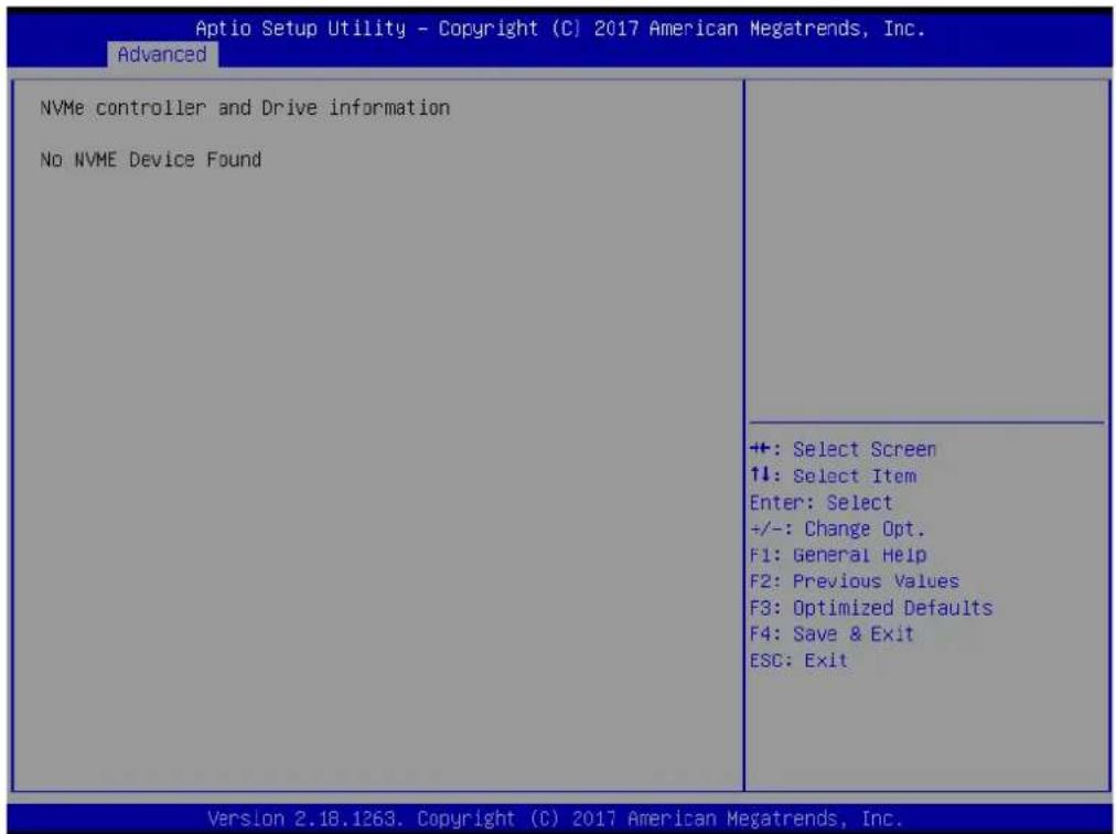
Figure 3.16 NVMe Configuration
3.4.9 SDIO Configuration
![Aptio Setup Utility - Copyright (C) 2017 American Megatrends, Inc. Advanced SDIO Configuration SDIO Access Mode [Auto] Auto Option: Access SD device in DMA mode if controller supports it,otherwise in PIO mode.DMA Option: Access SD device in DMA mode.PIO Option: Access SD device in PIO mode. +: Select Screen ↑1: Select Item Enter: Select +/-: Change Opt. F1: General Help F2: Previous Values F3: Optimized Defaults F4: Save & Exit ESC: Exit Version 2.18.1263. Copyright (C) 2017 American Megatrends, Inc.](/content/2026/06/1246723/images/e596dedd6200330f48e9057195d02bdfeb7d1b260e4a3849756d22ec93aee988.jpg)
Figure 3.17 SDIO Configuration
SDIO Access Mode
Auto Option: Access SD device in DMA mode if the controller supports it, otherwise in PIO mode.DMA Option: Access SD device in DMA mode.PIO Option: Access SD device in PIO mode.
3.4.10 USB Configuration
| Optio Setup Utility - Copyright (C) 2017 American Megatrends, Inc. Advanced | |
| USB Configuration USB Module Version 17 USB Controllers: 1 XHCI USB Devices: 1 Drive, 1 Keyboard Legacy USB Support [Enabled] XHCI Hand-off [Enabled] USB Mass Storage Driver Support [Enabled] | Enables Legacy USB support. AUTO option disables legacy support if no USB devices are connected. DISABLE option will keep USB devices available only for EFI applications. |
| USB hardware delays and time-outs: USB transfer time-out [20 sec] Device reset time-out [20 sec] Device power-up delay [Auto] | +: Select Screen ↑↓: Select Item Enter: Select +/-: Change Opt. F1: General Help F2: Previous Values F3: Optimized Defaults F4: Save & Exit ESC: Exit |
| Mass Storage Devices: Kingmax USB2.0 FlashDisk1.00 [Auto] | |
| Version 2.18.1263. Copyright (C) 2017 American Megatrends, Inc. | |
Figure 3.18 USB Configuration
Legacy USB Support
Enables Legacy USB support. AUTO option disables legacy support if no USB devices are connected. DISABLE option will keep USB devices available only for EFI applications.
XHCI Hand-off
This is a workaround for OS without XHCI hand-off support. The XHCI ownership change should be claimed by XHCI driver.
USB Mass Storage Driver Support
Enable/Disable USB Mass Storage Driver Support.
USB transfer time-out
The time-out value for Control, Bulk, and Interrupt transfers.
Device reset time-out
USB mass storage device Start Unit command time-out.
Device power-up delay
Maximum time the device will take before it properly reports itself to the Host Controller. 'Auto' uses default value: for a Root port it is 100 ms, for a Hub port the delay is taken from Hub descriptor.
Device power-up delay in seconds
Delay range is 1...40 seconds, in one second increments.
3.4.11 Platform Trust Technology
![Aptio Setup Utility - Copyright (C) 2017 American Megatrends, Inc. Advanced TPM Configuration fTPM [Disabled] Enable/Disable fTPM +: Select Screen 1+: Select Item Enter: Select +/-: Change Opt. F1: General Help F2: Previous Values F3: Optimized Defaults F4: Save & Exit ESC: Exit Version 2.18.1263. Copyright (C) 2017 American Megatrends, Inc.](/content/2026/06/1246723/images/013cea0ddf98baf89bf7627fd5ba43f9ad48c9eafb08754b1dfefd36ff98aee1.jpg)
Figure 3.19 Platform Trust Technology
fTPM
Enable/Disable fTPM
3.4.12 Security Configuration
![Aptio Setup Utility - Copyright (C) 2017 American Megatrends, Inc. Advanced TXE FW 3.0.12.1138 TXE HMRFPC [Disabled] TXE EOP Message [Enabled] +: Select Screen ↑↓: Select Item Enter: Select +/-: Change Opt. F1: General Help F2: Previous Values F3: Optimized Defaults F4: Save & Exit ESC: Exit Version 2.18.1263. Copyright (C) 2017 American Megatrends, Inc.](/content/2026/06/1246723/images/0426eb032033e52b32e51cb04e3cb815989911f0b5895703d857a461db0c4dc8.jpg)
Figure 3.20 Security Configuration
TXE HMRFPO
TXE EOP Message
Send EOP Message Before Enter OS
3.5 Chipset Setup
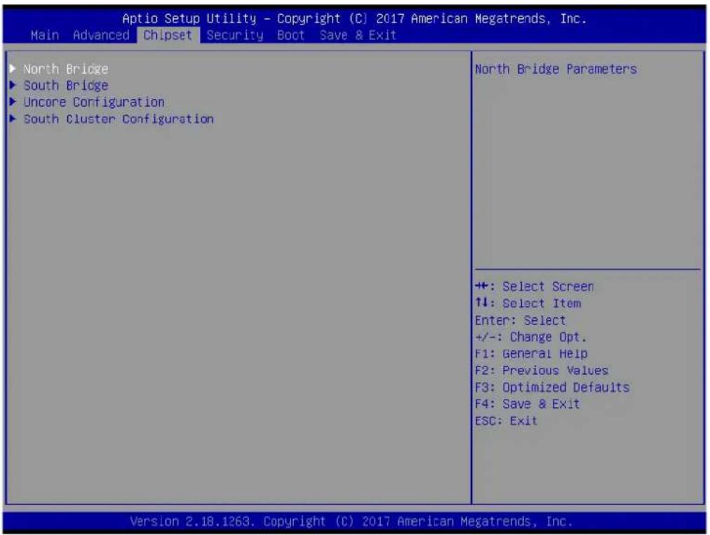
Figure 3.21 Chipset Setup
North Bridge
North Bridge Parameters
South Bridge
South Bridge Parameters
Uncore Configuration
Uncore Configuration
South Cluster Configuration
South Cluster Configuration
3.5.1 North Bridge
![Aptio Setup Utility - Copyright (C) 2017 American Megatrends, Inc. Chipset Memory Information Total Memory 2048 MB (LPDDR4) Memory Slot0 1024 MB (LPDDR4) Memory Slot1 1024 MB (LPDDR4) Memory Slot2 Not Present Memory Slot3 Not Present Above 4GB MMIO BIOS assignment [Disabled] Enable/Disable above 4GB MemoryMappedIO BIOS assignment This is disabled automatically when Aperture Size is set to 2048MB. +: Select Screen ↑↓: Select Item Enter: Select +/-: Change Opt. F1: General Help F2: Previous Values F3: Optimized Defaults F4: Save & Exit ESC: Exit Version 2.18.1263. Copyright (C) 2017 American Megatrends, Inc.](/content/2026/06/1246723/images/b66a9a55d463429b5048d363f9b785904876e841a9aa6c31cd2db3de948049aa.jpg)
Figure 3.22 North Bridge
Total Memory
Total Memory in the System.
Memory Slot0
Memory in the slot.
Memory Slot1
Memory in the slot.
Memory Slot2
Memory in the slot.
Memory Slot3
Memory in the slot.
Above 4GB MMIO BIOS assignment
Enable/Disable above 4GB MemoryMappedIO BIOS assignment. This is disabled automatically when Aperture Size is set to 2048MB.
3.5.2 South Bridge
![Aptio Setup Utility - Copyright (C) 2017 American Megatrends, Inc. Chipset Serial IRQ Mode [Continuous] Configure Serial IRQ Mode. +: Select Screen ↓: Select Item Enter: Select +/-: Change Opt. F1: General Help F2: Previous Values F3: Optimized Defaults F4: Save & Exit ESC: Exit Version 2.18.1263. Copyright (C) 2017 American Megatrends, Inc.](/content/2026/06/1246723/images/7422d3ebc75a6ef9410a73abc3b6ea5a25daa828745b32af27fe52d038d8bb51.jpg)
Figure 3.23 South Bridge
Serial IRQ Mode
Configure Serial IRQ Mode.
3.5.3 Uncore Configuration
![Aptio Setup Utility - Copyright (C) 2017 American Megatrends, Inc. Chipset IGD Configuration RC6(Render Standby) [Enable] IGD - LCD Control NXP non-EDID Support [Enabled] Color depth and packing format [JEDIA or VESA (18 bpp)] Dual LVDS mode [Single LVDS bus mode] LCD Panel Type [600x600] Check to enable render standby support, RC6 should be enabled if SOix is enabled. This item will be read only if SOix is enabled +: Select Screen ↑↓: Select Item Enter: Select +/-: Change Opt. F1: General Help F2: Previous Values F3: Optimized Defaults F4: Save & Exit ESC: Exit Version 2.18.1263. Copyright (C) 2017 American Megatrends, Inc.](/content/2026/06/1246723/images/da6a5b83c81b6e1a893a84d5e72849f5be3441d5aee7b6af3598f5a06b0f88ce.jpg)
Figure 3.24 Uncore Configuration
IGD Configuration
RC6(Render Standby)
Check to enable render standby support, RC6 should be enabled if S0ix is enabled. This item will be read only if S0ix is enabled.
IGD - LCD Control
NXP non-EDID Support
NXP PTN3460 Support: Enable: Used internal EDID setting; Disable: Get EDID from DDC bus.
Color depth and packing format
Color depth and packing format
Dual LVDS mode
Dual LVDS mode
LCD Panel Type
Select LCD panel used by Internal Graphics Device by selecting the appropriate setup item.
3.5.4 South Cluster Configuration
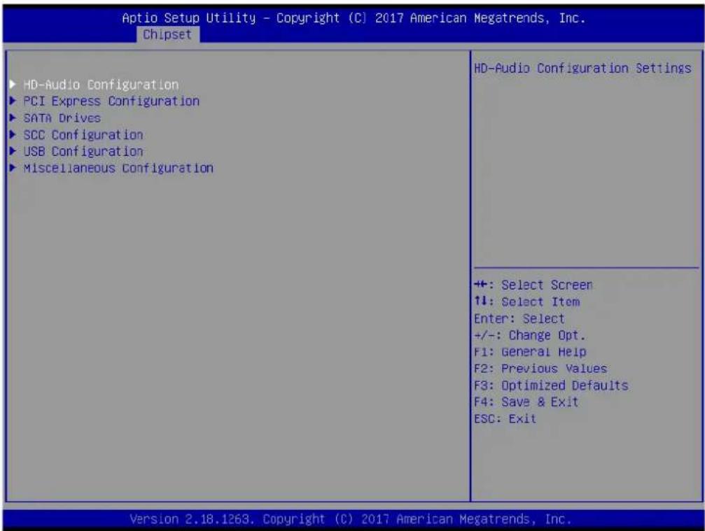
Figure 3.25 South Cluster Configuration
HD-Audio Configuration
HD-Audio Configuration Settings
PCI Express Configuration
PCI Express Configuration Settings
SATA Drives
Press
SCC Configuration
SCC Configuration Settings
USB Configuration
USB Configuration Settings
Miscellaneous Configuration
Enable/Disable Misc. Features
3.5.4.1 HD-Audio Configuration
![Aptio Setup Utility - Copyright (C) 2017 American Megatrends, Inc. Chipset HD-Audio Configuration HD-Audio Support [Enable] Enable/Disable HD-Audio Support ++: Select Screen ↑↓: Select Item Enter: Select +/-: Change Opt. F1: General Help F2: Previous Values F3: Optimized Defaults F4: Save & Exit ESC: Exit Version 2.18.1263. Copyright (C) 2017 American Megatrends, Inc.](/content/2026/06/1246723/images/898dff057899444138e69b54ad38d79c2f402a5ab321246799dbf503c3093b38.jpg)
Figure 3.26 HD-Audio Configuration
HD-Audio Support
Enable/Disable HD-Audio Support
3.5.4.2 PCI Express Configuration
![Aptio Setup Utility - Copyright (C) 2017 American Megatrends, Inc. Chipset PCI Express Configuration Compliance Mode [Disabled] ► LAN ► PCI Express Root Port 0 ► PCI Express Root Port 1 ► PCI Express Root Port 2 ► PCI Express Root Port 3 Compliance Mode Enable/Disable +: Select Screen ↑↓: Select Item Enter: Select +/-: Change Opt. F1: General Help F2: Previous Values F3: Optimized Defaults F4: Save & Exit ESC: Exit Version 2.18.1263. Copyright (C) 2017 American Megatrends, Inc.](/content/2026/06/1246723/images/c353470ea96866dd66f8a7684c73be5c7ab8dc7bdfa8df4dcc5eb6de7dcef82c.jpg)
Figure 3.27 PCI Express Configuration
Compliance Mode
Compliance Mode Enable/Disable
LAN
Control the PCI Express Root Port. AUTO: To disable unused root port automatically for the most optimum power savings. Enable: Enable PCIe root port Disable: Disable PCIe root port
PCI Express Root Port 0
Control the PCI Express Root Port. AUTO: To disable unused root port automatically for the most optimum power savings. Enable: Enable PCIe root port Disable: Disable PCIe root port
PCI Express Root Port 1
Control the PCI Express Root Port. AUTO: To disable unused root port automatically for the most optimum power savings. Enable: Enable PCIe root port Disable: Disable PCIe root port
PCI Express Root Port 2
Control the PCI Express Root Port. AUTO: To disable unused root port automatically for the most optimum power savings. Enable: Enable PCIe root port Disable: Disable PCIe root port
PCI Express Root Port 3
Control the PCI Express Root Port. AUTO: To disable unused root port automatically for the most optimum power savings. Enable: Enable PCIe root port Disable: Disable PCIe root port
LAN
![Aptio Setup Utility - Copyright (C) 2017 American Megatrends, Inc. Chipset LAN [Enable] If DISABLED, goto ENABLE first the ASPM [Disable] PCIe Speed [Auto] Control the PCI Express Root Port. AUTO: To disable unused root port automatically for the most optimum power savings. Enable: Enable PCIe root port Disable: Disable PCIe root port +: Select Screen ↑↓: Select Item Enter: Select +/-: Change Opt. F1: General Help F2: Previous Values F3: Optimized Defaults F4: Save & Exit ESC: Exit Version 2.18.1263. Copyright (C) 2017 American Megatrends, Inc.](/content/2026/06/1246723/images/65cede566a73685e418bcb0a46646832b9d6b1b5744b036d6572a8deacd5105a.jpg)
Figure 3.28 LAN
LAN
Control the PCI Express Root Port. AUTO: To disable unused root port automatically for the most optimum power savings. Enable: Enable PCIe root port Disable: Disable PCIe root port
ASPM
PCI Express Active State Power Management settings
PCIe Speed
Configure PCIe Speed
PCI Express Root Port 0
![Aptio Setup Utility - Copyright (C) 2017 American Megatrends, Inc. Chipset PCI Express Root Port 0 [Enable] If DISABLED, goto ENABLE first the ASPM [Disable] PCIe Speed [Auto] Control the PCI Express Root Port. AUTO: To disable unused root port automatically for the most optimum power savings. Enable: Enable PCIe root port Disable: Disable PCIe root port +: Select Screen ↑↓: Select Item Enter: Select +/-: Change Opt. F1: General Help F2: Previous Values F3: Optimized Defaults F4: Save & Exit ESC: Exit Version 2.18.1263. Copyright (C) 2017 American Megatrends, Inc.](/content/2026/06/1246723/images/2d24e1a2d2bc135096f72674f925087c00cdf1a091035693de7ab703337ec29c.jpg)
Figure 3.29 PCI Express Root Port 0
PCI Express Root Port 0
Control the PCI Express Root Port. AUTO: To disable unused root port automatically for the most optimum power savings. Enable: Enable PCIe root port Disable: Disable PCIe root port
ASPM
PCI Express Active State Power Management settings
PCIe Speed
Configure PCIe Speed
PCI Express Root Port 1
![Aptio Setup Utility - Copyright (C) 2017 American Megatrends, Inc. Chipset PCI Express Root Port 1 [Enable] If DISABLED, goto ENABLE first the ASPM [Disable] PCIe Speed [Auto] Control the PCI Express Root Port. AUTO: To disable unused root port automatically for the most optimum power savings. Enable: Enable PCIe root port Disable: Disable PCIe root port +: Select Screen ↑↓: Select Item Enter: Select +/-: Change Opt. F1: General Help F2: Previous Values F3: Optimized Defaults F4: Save & Exit ESC: Exit Version 2.18.1263. Copyright (C) 2017 American Megatrends, Inc.](/content/2026/06/1246723/images/97a50ddea0750c69a5255cf8c32b1b3ff96756f3cf5937626344602ebf393e98.jpg)
Figure 3.30 PCI Express Root Port 1
PCI Express Root Port 1
Control the PCI Express Root Port. AUTO: To disable unused root port automatically for the most optimum power savings. Enable: Enable PCIe root port Disable: Disable PCIe root port
ASPM
PCI Express Active State Power Management settings
PCIe Speed
Configure PCIe Speed
PCI Express Root Port 2
![Aptio Setup Utility - Copyright (C) 2017 American Megatrends, Inc. Chipset PCI Express Root Port 2 [Enable] If DISABLED, goto ENABLE first the ASPM [Disable] PCIe Speed [Auto] Control the PCI Express Root Port. AUTO: To disable unused root port automatically for the most optimum power savings. Enable: Enable PCIe root port Disable: Disable PCIe root port +: Select Screen ↑↓: Select Item Enter: Select +/-: Change Opt. F1: General Help F2: Previous Values F3: Optimized Defaults F4: Save & Exit ESC: Exit Version 2.18.1263. Copyright (C) 2017 American Megatrends, Inc.](/content/2026/06/1246723/images/09cae0f50f0e20e139f0f9c4436169c51973d520b6acebe83f51f24b7f3d2051.jpg)
Figure 3.31 PCI Express Root Port 2
PCI Express Root Port 2
Control the PCI Express Root Port. AUTO: To disable unused root port automatically for the most optimum power savings. Enable: Enable PCIe root port Disable: Disable PCIe root port
ASPM
PCI Express Active State Power Management settings
PCIe Speed
Configure PCIe Speed
PCI Express Root Port 3
![Aptio Setup Utility - Copyright (C) 2017 American Megatrends, Inc. Chipset PCI Express Root Port 3 [Enable] If DISABLED, goto ENABLE first the ASPM [Disable] PCIe Speed [Auto] Control the PCI Express Root Port. AUTO: To disable unused root port automatically for the most optimum power savings. Enable: Enable PCIe root port Disable: Disable PCIe root port +: Select Screen ↓: Select Item Enter: Select +/-: Change Opt. F1: General Help F2: Previous Values F3: Optimized Defaults F4: Save & Exit ESC: Exit Version 2.18.1263. Copyright (C) 2017 American Megatrends, Inc.](/content/2026/06/1246723/images/57bca26a47270a937c173a90fb4a865d0b67168e9fb81b74056ed95287b09156.jpg)
Figure 3.32 PCI Express Root Port 3
PCI Express Root Port 3
Control the PCI Express Root Port. AUTO: To disable unused root port automatically for the most optimum power savings. Enable: Enable PCIe root port Disable: Disable PCIe root port
ASPM
PCI Express Active State Power Management settings
PCIe Speed
Configure PCIe Speed
3.5.4.3 SATA Drive
![Aptio Setup Utility - Copyright (C) 2017 American Megatrends, Inc. Chipset SATA Drives Chipset-SATA Controller Configuration Chipset SATA [Enable] SATA Mode Selection [AHCI] SATA Port 0 [Not Installed] Port 0 [Enabled] SATA Port 1 [Not Installed] Port 1 [Enabled] Enables or Disables the Chipset SATA Controller. The Chipset SATA controller supports the 2 black internal SATA ports (up to 3Gb/s supported per port). +: Select Screen ↑↓: Select Item Enter: Select +/-: Change Opt. F1: General Help F2: Previous Values F3: Optimized Defaults F4: Save & Exit ESC: Exit Version 2.18.1263. Copyright (C) 2017 American Megatrends, Inc.](/content/2026/06/1246723/images/6003fb7df1a5aaffbaba0788d9071a1b10939bce129e698dcd51393fe2f3b6b4.jpg)
Figure 3.33 SATA Drives
Chipset-SATA Controller Configuration
Chipset SATA
Enables or Disables the Chipset SATA Controller. The Chipset SATA controller supports the 2 black internal SATA ports (up to 3Gb/s supported per port).
SATA Mode Selection
Determines how SATA controller(s) operate.
SATA Port 0
Port 0
Enable or Disable SATA Port
SATA Port 1
Port 1
Enable or Disable SATA Port
3.5.4.4 SCC Configuration
![Aptio Setup Utility - Copyright (C) 2017 American Megatrends, Inc. Chipset SCC SD Card Support (D27:F0) [Enable] SCC eMMC Support (D28:F0) [Enable] eMMC Max Speed [HS400] Enable/Disable SCC SD Card Support +: Select Screen ↑↓: Select Item Enter: Select +/-: Change Opt. F1: General Help F2: Previous Values F3: Optimized Defaults F4: Save & Exit ESC: Exit Version 2.18.1263. Copyright (C) 2017 American Megatrends, Inc.](/content/2026/06/1246723/images/40764d92be9ea3fe27837c153091c522c5a09b526e6bb4df6bedf8b136240a78.jpg)
Figure 3.34 SCC Configuration
SCC SD Card Support (D27:F0)
Enable/Disable SCC SD Card Support
SCC eMMC Support (D28:F0)
Enable/Disable SCC eMMC Support
eMMC Max Speed
Select the eMMC max Speed allowed.
3.5.4.5 USB Configuration
![Aptio Setup Utility - Copyright (C) 2017 American Megatrends, Inc. Chipset XHCI Mode [Enable] XDCI Support [Disable] USB HW MODE AFE Comparators [Disable] Once disabled, XHCI controller would be function disabled, none of the USB devices are detectable and usable during boot and in OS. Do not disable it unless for debug purpose. ++ : Select Screen ↑↓: Select Item Enter: Select +/-: Change Opt. F1: General Help F2: Previous Values F3: Optimized Defaults F4: Save & Exit ESC: Exit Version 2.18.1253. Copyright (C) 2017 American Megatrends, Inc.](/content/2026/06/1246723/images/55500033cdb117cdfa687186756b5e9ffe9f8478383e8968ad190c1f53115a66.jpg)
Figure 3.35 USB Configuration
xHCI Mode
Once disabled, XHCI controller would be function disabled, none of the USB devices are detectable and usable during boot and in OS. Do not disable it unless for debug purpose.
XDCI Support
Enable/Disable XDCI
USB HW MODE AFE Comparators
Enable/Disable USB HW MODE AFE Comparators
3.5.4.6 Miscellaneous Configuration
![Aptio Setup Utility - Copyright (C) 2017 American Megatrends, Inc. Chipset Miscellaneous Configuration State After G3 [S5 State] Wake On Lan [Enable] BIOS Lock [Enabled] Specify what state to go to when power is re-applied after a power failure (G3 state). S0 State: System will boot directly as soon as power applied. S5 State: System keeps in power-off state until power button is pressed. +: Select Screen ↑↓: Select Item Enter: Select +/-: Change Opt. F1: General Help F2: Previous Values F3: Optimized Defaults F4: Save & Exit ESC: Exit Version 2.18.1263. Copyright (C) 2017 American Megatrends, Inc.](/content/2026/06/1246723/images/ac8e8d610e26586cbd1991c5a4693f88d3cbf0c5eac30a9e860de2d936b7eb91.jpg)
Figure 3.36 Miscellaneous Configuration
State After G3
Specify what state to go to when power is re-applied after a power failure (G3 state). S0 State: System will boot directly as soon as power applied. S5 State: System keeps in power-off state until power button is pressed.
Wake On Lan
Enable or Disable the Wake on Lan.
BIOS Lock
Enable/Disable the SC BIOS Lock Enable feature. Required to be enabled to ensure SMM protection of flash.
3.6 Security Chipset
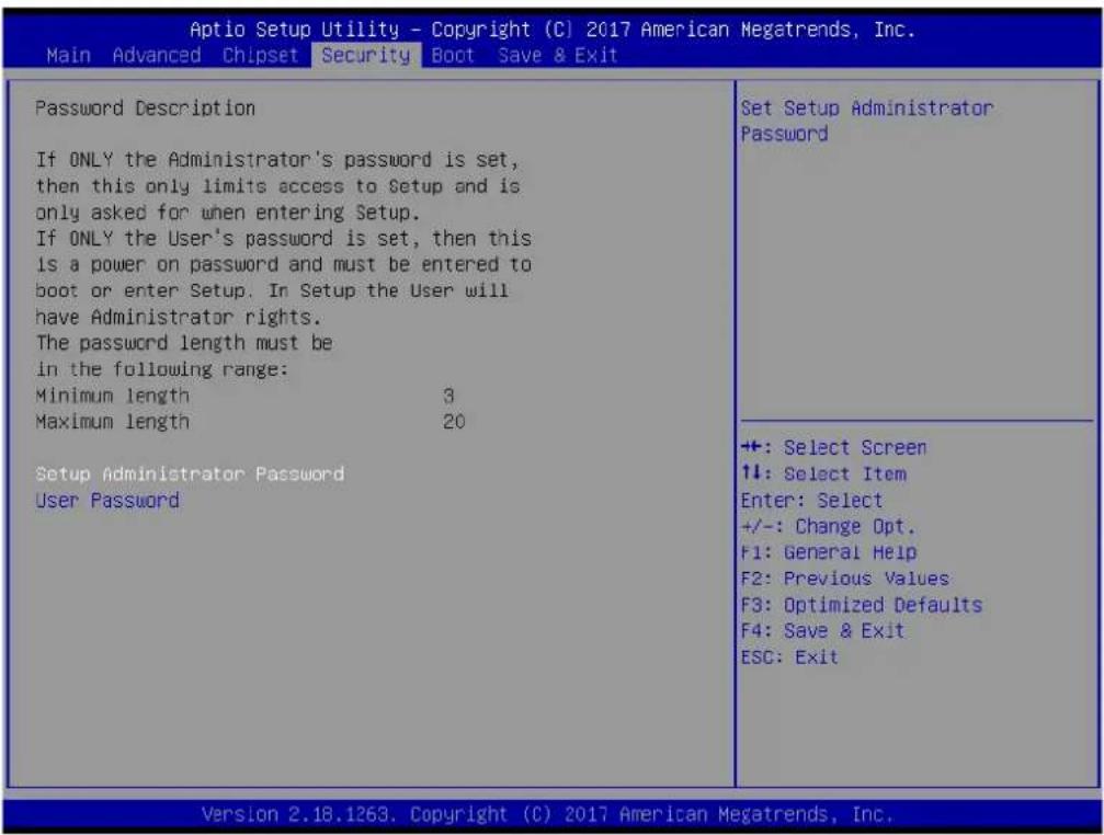
Figure 3.37 Security Chipset
Setup Administrator Password
Set Setup Administrator Password
User Password
Set User Password
3.7 Boot Setup
![Aptio Setup Utility - Copyright (C) 2017 American Megatrends, Inc. Main Advanced Chipset Security Boot Save & Exit Boot Configuration Setup Prompt Timeout Bootup NumLock State Quiet Boot Boot Option Priorities Boot Option #1 Fast Boot 1 [On] [Disabled] [LEFI: Kingmax USB2...] [Disable] Number of seconds to wait for setup activation key. 65535(0xFFFF) means indefinite waiting. +: Select Screen ↑↓: Select Item Enter: Select +/-: Change Opt. F1: General Help F2: Previous Values F3: Optimized Defaults F4: Save & Exit ESC: Exit Version 2.18.1263. Copyright (C) 2017 American Megatrends, Inc.](/content/2026/06/1246723/images/589893de70b148bcf5d44655f0f8d0ee18f61083e226c796565accffaac16f00.jpg)
Figure 3.38 Boot Setup
Boot Configuration
Setup Prompt Timeout
Number of seconds to wait for setup activation key. 65535(0xFFFF) means indefinite waiting.
Bootup NumLock State
Select the keyboard NumLock state
Quiet Boot
Enables or disables Quiet Boot option
Boot Option Priorities
Boot Option #1
Sets the system boot order
Fast Boot
Enable or Disable FastBoot features. Most probes are skipped to reduce time cost during boot.
3.8 Save & Exit
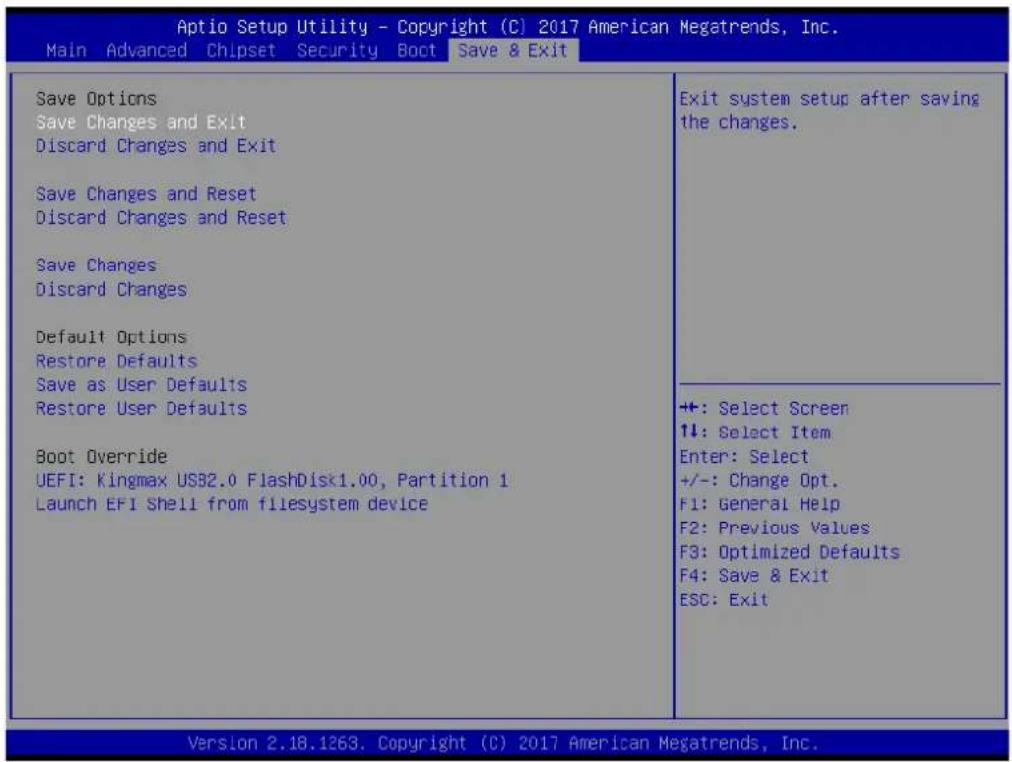
Figure 3.39 Save & Exit
Save Options
Save Changes and Exit
Exit system setup after saving the changes.
Discard Changes and Exit
Exit system setup without saving any changes.
Save Changes and Reset
Reset the system after saving the changes.
Discard Changes and Reset
Reset system setup without saving any changes.
Default Options
Restore Defaults
Restore/Load Default values for all the setup options.
Save as User Defaults
Save the changes done so far as User Defaults.
Restore the User Defaults to all the setup options.
Boot Override
Launch EFI Shell from file system device
Attempts to Launch EFI Shell application (Shell.efi) from one of the available filesystem devices
Chapter 4
S/W Introduction & Installation
S/W Introduction
Driver Installation
Advantech iManager
4.1 S/W Introduction
The mission of Advantech Embedded Software Services is to "Enhance quality of life with Advantech platforms and Microsoft Windows embedded technology." We enable Windows Embedded software products on Advantech platforms to more effectively support the embedded computing community. Customers are freed from the hassle of dealing with multiple vendors (Hardware suppliers, System integrators, Embedded OS distributor) for projects. Our goal is to make Windows Embedded Software solutions easily and widely available to the embedded computing community.
4.2 Driver Installation
The Intel Chipset Software Installation (CSI) utility installs the Windows INF files that outline to the operating system how the chipset components will be configured.
4.2.1 Windows Driver Setup
To install the drivers on a windows-based operation system, please connect to internet and browse the website http://support.advantech.com.tw and download the drivers that you want to install and follow Driver Setup instructions to complete the installation.
4.2.2 Other OS
SOM-3569 supports Linux.
4.3 Advantech iManager
Advantech's platforms come equipped with iManager, a micro controller that provides embedded features for system integrators. Embedded features have been moved from the OS/BIOS level to the board level, to increase reliability and simplify integration.
iManager runs whether the operating system is running or not; it can count the boot times and running hours of the device, monitor device health, and provide an advanced watchdog to handle errors just as they happen. iManager also comes with a secure & encrypted EEPROM for storing important security key or other customer define information. All the embedded functions are configured through API and provide corresponding utilities to demonstrate. These APIs comply with PICMG EAPI (Embedded Application Programmable Interface) specification and unify in the same structures. It makes these embedded features easier to integrate, speed up developing schedule, and provide the customer's software continuity while upgrade hardware. More detail of how to use the APIs and utilities, please refer to Advantech iManager 2.0 Software API User Manual.
Control

GPIO
General Purpose Input/Output is a flexible parallel interface that allows a variety of custom connections. It allows users to monitor the level of signal input or set the output status to switch on/off a device. Our API also provides Programmable GPIO, which allows developers to dynamically set the GPIO input or output status.

SMBus
SMBus is the System Management Bus defined by Intel® Corporation in 1995. It is used in personal computers and servers for low-speed system management communications. The SMBus API allows a developer to interface a embedded system environment and transfer serial messages using the SMBus protocols, allowing multiple simultaneous device control.

PC
PC is a bi-directional two wire bus that was developed by Philips for use in their televisions in the 1960s. The PC API allows a developer to interface with an embedded system environment and transfer serial messages using the PC protocols, allowing multiple simultaneous device control.
Display

Brightness Control
The Brightness Control API allows a developer to interface with an embedded device to easily control brightness.

Backlight
The Backlight API allows a developer to control the backlight (screen) on/off in an embedded device.
Monitor

Watchdog
A watchdog timer (WDT) is a device that performs a specific operation after a certain period of time if something goes wrong and the system does not recover on its own. A watchdog timer can be programmed to perform a warm boot (restarting the system) after a certain number of seconds.

Hardware Monitor
The Hardware Monitor (HWM) API is a system health supervision API that inspects certain condition indexes, such as fan speed, temperature and voltage.

Hardware Control
The Hardware Control API allows developers to set the PWM (Pulse Width Modulation) value to adjust fan speed or other devices; it can also be used to adjust the LCD brightness.
Power Saving

CPU Speed
Make use of Intel SpeedStep technology to reduce power power consumption. The system will automatically adjust the CPU Speed depending on system loading.

System Throttling
Refers to a series of methods for reducing power consumption in computers by lowering the clock frequency. These APIs allow the user to lower the clock from 87.5% to 12.5%.
Appendix A
Pin Assignment
This appendix gives you the information about the hardware pin assignment of the SOM-3569 CPU System on Module
Sections include:
■ SOM-3569 Qseven R2.1 Pin Assignment
A.1 SOM-3569 Qseven R2.1 Pin Assignment
This section gives SOM-3569 pin assignment on Qseven golden finger which compliant with Qseven R2.1 pin-out definitions. More details about how to use these pins and get design reference. Please contact to Advantech for design guide, checklist, reference schematic, and other hardware/software supports.
| Odd number | R2.1 SOM-3569 A101-2 | Even number | R2.1 SOM-3569 A101-2 |
| 1 | G | N | D |
| 3 GBE_MDI3- 4 GBE_MDI2- | |||
| 5 | GBE_MDI3+ | 6 | GBE_MDI2+ |
| 7 | GBE_LINK100# | 8 | GBE_LINK1000# |
| 9 | GBE_MDI1- | 10 | GBE_MDI0- |
| 11 | GBE_MDI1+ | 12 | GBE_MDI0+ |
| 13 | GBE_LINK# | 14 | GBE_ACT# |
| 15 NC 16 SUS_S4# | |||
| 17 WAKE# 18 SUS_S3# | |||
| 19 GPO0 | 20 PWRBTN# | ||
| 21 | SLP_BTN# | 22 | LID_BTN# |
| 23 | GND | 24 | GNC |
| KEY | KEY | ||
| 25 | GND | 26 | PWC |
| 27 | BATLOW# | 28 | RSTBTN# |
| 29 | SATA0_TX+ | 30 | SATA1_TX+ |
| 31 | SATA0_TX- | 32 | SATA1_TX- |
| 33 | SATA_ACT# | 34 | GND |
| 35 | SATA0_RX+ | 36 | SATA1_RX+ |
| 37 | SATA0_RX- | 38 | SATA1_RX- |
| 39 GND | 40 GND | ||
| 41 BIOS_DISABLE# | 42 SDIO_CLK# | ||
| 43 | SDIO_CD# | 44 | NC |
| 45 SDIO_CMD | 46 SDIO_WP | ||
| 47 SDIO_PWR# | 48 SDIO_DAT1 | ||
| 49 | SDIO_DAT0 | 50 | SDIO_DAT3 |
| 51 | SDIO_DAT2 | 52 | NC |
| 53 NC 54 NC | |||
| 55 NC 56 USB_OTG_PEN | |||
| 57 | GND | 58 | GNC |
| 59 | HDA_SYNC | 60 | SMB_CLK |
| 61 | HDA_RST# | 62 | SMB_DAT |
| 63 | HDA_BITCLK | 64 | SMB_ALERT# |
| 65 | HDA_SDI | 66 | I2C_CLK |
| 67 HDA_SDO | 68 I2C_DAT | ||
| 69 | THRM# | 70 | WDTRIG# |
| 71 | THRMTRIP# | 72 | WDOUT |
| 73 | GND | 74 | |
| 75 USB_SSTX0- 76 USB_SSRX0- | |||
| 77 USB_SSTX0+ 78 USB_SSRX0+ | |||
| 79 USB_6_7_OC# 80 USB_4_5_OC# | |||
| 81 | USB_P5- | 82 | USB_P4- |
| 83 | USB_P5+ | 84 | USB_P4+ |
| 85 | USB_2_3_OC# | 86 | USB_0_1_OC# |
| 87 | USB_P3- | 88 | USB_P2- |
| 89 | USB_P3+ | 90 | USB_P2+ |
| 91 USB_VBUS 92 USB_ID | |||
| 93 | USB_P1- | 94 | USB_P0- |
| 95 | USB_P1+ | 96 | USB_P0+ |
| 97 | GND | 98 | |
| 99 eDP0_TX0+ / LVDS_A0+ 100 LVDS_B0+ | |||
| 101 eDP0_TX0- / LVDS_A0- 102 LVDS_B0- | |||
| 103 eDP0_TX1+ / LVDS_A1+ 104 LVDS_B1+ | |||
| 105 eDP0_TX1- / LVDS_A1- 106 LVDS_B1- | |||
| 107 eDP0_TX2+ / LVDS_A2+ 108 LVDS_B2+ | |||
| 109 eDP0_TX2- / LVDS_A2- 110 LVDS_B2- | |||
| 111 | LVDS_PPEN | 112 | LVDS_BLEN |
| 113 | eDP0_TX3+ / LVDS_A3+ | 114 | LVDS_B3+ |
| 115 | eDP0_TX3- / LVDS_A3- 116 LVDS_B3- | ||
| 117 | GND | 118 | GND |
| 119 | eDP0_AUX+ / LVDS_A_CLK+ | 120 LVDS_B_CLK+ | |
| 121 eDP0_AUX- / LVDS_A_CLK- | 122 LVDS_B_CLK- | ||
| 123 | LVDS_BLT_CTRL | 124 | NC |
| 125 | LVDS_DID_DAT | 126 | eDP0_HPD# |
| 127 | LVDS_DID_CLK | 128 | NC |
| 129 CAN0_TX | 130 CAN0_RX | ||
| 131 DP_LANE3+ | 132 USB_SSTX1- | ||
| 133 DP_LANE3- | 134 USB_SSTX1+ | ||
| 135 | GND | 136 | |
| 137 | DP_LANE1+ | 138 | DP_AUX+ |
| 139 DP_LANE1- | 140 DP_AUX- | ||
| 141 | GND | 142 | |
| 143 DP_LANE2+ | 144 USB_SSRX1- | ||
| 145 DP_LANE2- | 146 USB_SSRX1+ | ||
| 147 | GND | 148 | |
| 149 DP_LANE0+ | 150 HDMI_CTRL_DAT | ||
| 151 DP_LANE0- | 152 HDMI_CTRL_CLK | ||
| 153 | HDMI_HPD# | 154 | DP_HPD# |
| 155 | PCIE_CLK_REF+ | 156 | PCIE_WAKE# |
| 157 | PCIE_CLK_REF- | 158 | PCIE_RST# |
| 159 | GND | 160 | |
| 161 | PCIE3_TX+ | 162 | PCIE3_RX+ |
| 163 | PCIE3_TX- | 164 | PCIE3_RX- |
| 165 | GND | 166 | |
| 167 | PCIE2_TX+ | 168 | PCIE2_RX+ |
| 169 PCIE2_TX- 170 PCIE2_RX- | |||
| 171 UART0_TX 172 UART0_RTS# | |||
| 173 | PCIE1_TX+ | 174 | PCIE1_RX+ |
| 175 | PCIE1_TX- | 176 | PCIE1_RX- |
| 177 | UART0_RX | 178 | UART0_CTS# |
| 179 | PCIE0_TX+ | 180 | PCIE0_RX+ |
| 181 | PCIE0_TX- | 182 | PCIE0_RX- |
| 183 | GND | 184 | G |
| 185 | LPC_AD0 | 186 | LPC_AD1 |
| 187 | LPC_AD2 | 188 | LPC_AD3 |
| 189 | LPC_CLK | 190 | LPC_FRAM |
| 191 | SERIRQ | 192 | NC |
| 193 | VCC_RTC | 194 | SPKR |
| 195 | FAN_TACHOIN | 196 | FAN_PWMOUT |
| 197 | GND | 198 | G |
| 199 SPI_MOSI 200 SPI_CS0# | |||
| 201 SPI_MISO 202 SPI_CS1# | |||
| 203 SPI_SCK 204 PULL LOW | |||
| 205 | VCC_5V_SB | 206 | VCC_5V_SB |
| 207 RDC_COM2_CTS# 208 RDC_COM2_SIN | |||
| 209 RDC_COM2_SOUT 210 RDC_COM2_RTS# | |||
| 211 NC 212 NC | |||
| 213 NC 214 NC | |||
| 215 NC 216 NC | |||
| 217 NC 218 NC | |||
| 219 | VCC | 220 | V |
| 221 | VCC | 222 | V |
| 223 | VCC | 224 | V |
| 225 | VCC | 226 | V |
| 227 | VCC | 228 | V |
| 229 | VCC | 230 | V |
Appendix B
Watchdog Timer
This appendix gives you the information about the watchdog timer programming on the SOM-3569 CPU System on Module
Sections include:
■ Watchdog Timer Programming
B.1 Programming the Watchdog Timer
Trigger Event Note
IRQ (BIOS setting default disable)**
NMI N/A
SCI Power button event
Power Off Support
H/W Restart Support
WDT Pin Activate Support
** WDT new driver support automatically select available IRQ number from BIOS, and then set to EC. Only Win10 support it.
In other OS, it will still use IRQ number from BIOS setting as usual.
For details, please refer to iManager & Software API User Manual.
Appendix C
System Assignments
This appendix gives you the information about the system resource allocation on the SOM-3569 CPU System on Module
Sections include:
System I/O ports
■ DMA Channel Assignments
Interrupt Assignments
1st MB Memory Map
C.1 System I/O Ports
Table C.1: System I/O ports
| Resource Device | |
| 0x00000299-0x0000029A Motherboard resources | |
| 0x000002C0-0x000002DF Motherboard resources | |
| 0x000002A0-0x000002BF Motherboard resources | |
| 0x00000290-0x0000029F Motherboard resources | |
| 0x0000029E-0x000002AD Motherboard resources | |
| 0x00000060-0x0000006F Motherboard resources | |
| 0x00000280-0x0000028F Motherboard resources | |
| 0x000002F0-0x000002F7 Motherboard resources | |
| 0x0000002E-0x0000002F Motherboard resources | |
| 0x0000004E-0x0000004F Motherboard resources | |
| 0x00000061-0x00000061 Motherboard resources | |
| 0x00000063-0x00000063 Motherboard resources | |
| 0x00000065-0x00000065 Motherboard resources | |
| 0x00000067-0x00000067 Motherboard resources | |
| 0x00000070-0x00000070 Motherboard resources | |
| 0x00000070-0x00000070 System CMOS/real time clock | |
| 0x00000080-0x0000008F Motherboard resources | |
| 0x00000092-0x00000092 Motherboard resources | |
| 0x000000B2-0x000000B3 Motherboard resources | |
| 0x00000680-0x0000069F Motherboard resources | |
| 0x00000400-0x0000047F Motherboard resources | |
| 0x00000500-0x000005FE Motherboard resources | |
| 0x00000600-0x0000061F Motherboard resources | |
| 0x0000164E-0x0000164F Motherboard resources | |
| 0x00000062-0x00000062 Microsoft ACPI-Compliant Embedded Controller | |
| 0x00000066-0x00000066 Microsoft ACPI-Compliant Embedded Controller | |
| 0x0000F040-0x0000F05F Intel(R) Celeron(R)/Pentium(R) Processor SMBUS - 5AD4 | |
| 0x000003F8-0x000003FF Communications Port (COM1) | |
| 0x000002F8-0x000002FF Communications Port (COM2) | |
| 0x00000200-0x0000027F FuncDrv_CANController_IO for ACPI PNP1070 | |
| 0x00000000-0x0000006F PCI Express Root Complex | |
| 0x00000078-0x00000CF7 PCI Express Root Complex | |
| 0x00000D00-0x0000FFFF PCI Express Root Complex | |
| 0x00000020-0x00000021 Programmable interrupt controller | |
| 0x00000024-0x00000025 Programmable interrupt controller | |
| 0x00000028-0x00000029 Programmable interrupt controller | |
| 0x0000002C-0x0000002D Programmable interrupt controller | |
| 0x00000030-0x00000031 Programmable interrupt controller | |
| 0x00000034-0x00000035 Programmable interrupt controller | |
| 0x00000038-0x00000039 Programmable interrupt controller | |
| 0x0000003C-0x0000003D Programmable interrupt controller | |
| 0x000000A0-0x000000A1 Programmable interrupt controller | |
| 0x000000A4-0x000000A5 Programmable interrupt controller | |
| 0x000000A8-0x000000A9 Programmable interrupt controller | |
| 0x000000AC-0x000000AD Programmable interrupt controller | |
| 0x000000B0-0x000000B1 Programmable interrupt controller | |
| 0x000000B4-0x000000B5 Programmable interrupt controller | |
| 0x000000B8-0x000000B9 Programmable interrupt controller | |
| 0x000000BC-0x000000BD Programmable interrupt controller | |
| 0x000004D0-0x000004D1 Programmable interrupt controller | |
| 0x0000F000-0x0000F03F Intel(R) HD Graphics | |
| 0x0000E000-0x0000EFFF | Intel(R) Celeron(R)/Pentium(R) Processor PCI Express Root Port - 5AD7 |
| 0x0000F090-0x0000F097 Standard SATA AHCI Controller | |
| 0x0000F080-0x0000F083 Standard SATA AHCI Controller | |
| 0x0000F060-0x0000F07F Standard SATA AHCI Controller | |
| 0x00000040-0x00000043 System timer | |
| 0x00000050-0x00000053 System timer | |
C.2 Interrupt Assignments
Table C.2: Interrupt Assignments
| Resource Device | |
| IRQ 0 System timer | |
| IRQ 3 Communications Port (COM2) | |
| IRQ 4 Communications Port (COM1) | |
| IRQ 6 FuncDrv_CANController_IO for ACPI PNP1070 | |
| IRQ 8 System CMOS/real time clock | |
| IRQ 14 Intel(R) Serial IO GPIO Host Controller - INT3452 | |
| IRQ 14 ApolloLake SD Card - 5ACA | |
| IRQ 25 High Definition Audio Controller | |
| IRQ 31 Intel(R) Serial IO I2C Host Controller - 5AB4 | |
| IRQ 39 ApolloLake eMMC - 5ACC | |
| IRQ 1024 ApolloLake SD Card - 5ACA | |
| IRQ 4294967279 Intel(R) Imaging Signal Processor 2600 | |
| IRQ 4294967280 Intel(R) USB 3.0 eXtensible Host Controller - 1.0 (Microsoft) | |
| IRQ 4294967281~ Intel(R) I211 Gigabit Network Connection | |
| IRQ 4294967286 | |
| IRQ 4294967287 Intel(R) Trusted Execution Engine Interface | |
| IRQ 4294967288 Intel(R) HD Graphics | |
| IRQ 4294967289 Standard SATA AHCI Controller | |
| IRQ 4294967290 | Intel(R) Celeron(R)/Pentium(R) Processor PCI Express Root Port - 5AD7 |
| IRQ 4294967291 | Intel(R) Celeron(R)/Pentium(R) Processor PCI Express Root Port - 5ADB |
| IRQ 4294967292 | Intel(R) Celeron(R)/Pentium(R) Processor PCI Express Root Port - 5ADA |
| IRQ 4294967293 | Intel(R) Celeron(R)/Pentium(R) Processor PCI Express Root Port - 5AD9 |
| IRQ 4294967294 | Intel(R) Celeron(R)/Pentium(R) Processor PCI Express Root Port - 5AD8 |
C.3 1st MB Memory Map
Table C.3: 1st MB Memory Map
| Resource Device | |
| 0xE0000000-0xEFFFFFFF Motherboard resources | |
| 0xE0000000-0xEFFFFFFF PCI Express Root Complex | |
| 0xFEA00000-0xFEAFFFFFF Motherboard resources | |
| 0xFED01000-0xFED01FFF Motherboard resources | |
| 0xFED03000-0xFED03FFF Motherboard resources | |
| 0xFED06000-0xFED06FFF Motherboard resources | |
| 0xFED08000-0xFED09FFF Motherboard resources | |
| 0xFED80000-0xFEDBFFFF Motherboard resources | |
| 0xFED1C000-0xFED1CFFF Motherboard resources | |
| 0xFEE00000-0xFEEFFFFFF Motherboard resources | |
| 0x82210000-0x82213FFF High Definition Audio Controller | |
| 0x82000000-0x820FFFFFF High Definition Audio Controller | |
| 0x82216000-0x822160FF | Intel(R) Celeron(R)/Pentium(R) Processor SMBUS - 5AD4 |
| 0x82218000-0x82218FFF ApolloLake eMMC - 5ACC | |
| 0x82217000-0x82217FFF ApolloLake eMMC - 5ACC | |
| 0x8221C000-0x8221CFFF Intel(R) Serial IO I2C Host Controller - 5AB4 | |
| 0x8221B000-0x8221BFFF Intel(R) Serial IO I2C Host Controller - 5AB4 | |
| 0xFED00000-0xFED003FF High precision event timer | |
| 0x82200000-0x8220FFFF | Intel(R) USB 3.0 eXtensible Host Controller - 1.0 (Microsoft) |
| 0xA0000-0xBFFFF | PCI Express Root Complex |
| 0xC0000-0xDFFFF | PCI Express Root Complex |
| 0xE0000-0xFFFF | PCI Express Root Complex |
| 0x7C000001-0x7FFFFFF | PCI Express Root Complex |
| 0x7B800001-0x7BFFFFFF | PCI Express Root Complex |
| 0x80000000-0xCFFFFFF | PCI Express Root Complex |
| 0x82221000-0x82221FFF Intel(R) Trusted Execution Engine Interface | |
| 0x81000000-0x81FFFFFF | Intel(R) HD Graphics |
| 0x90000000-0x9FFFFFF Intel(R) HD Graphics | |
| 0xD0C00000-0xD0C00653 | Intel(R) Serial IO GPIO Host Controller - INT3452 |
| 0x82100000-0x821FFFF | Intel(R) Celeron(R)/Pentium(R) Processor PCI Express Root Port - 5AD7 |
| 0x82100000-0x821FFFF Intel(R) I211 Gigabit Network Connection | |
| 0x8221A000-0x8221AFFF ApolloLake SD Card - 5ACA | |
| 0x82219000-0x82219FFF ApolloLake SD Card - 5ACA | |
| 0x82214000-0x82215FFF Standard SATA AHCI Controller | |
| 0x8221E000-0x8221E0FF | Standard SATA AHCI Controller |
| 0x8221D000-0x8221D7FF | Standard SATA AHCI Controller |
| 0x82120000-0x82123FFF Intel(R) I211 Gigabit Network Connection | |
| 0xCF000000-0xCFFFFFF Intel(R) Imaging Signal Processor 2600 | |
ADVANTECH
Enabling an Intelligent Planet
www.advantech.com
Please verify specifications before quoting. This guide is intended for reference purpOS only.
All product specifications are subject to change without notice.
No part of this publication may be reproduced in any form or by any means, electronic, photocopying, recording or otherwise, without prior written permission of the publisher.
All brand and product names are trademarks or registered trademarks of their respective companies.
© Advantech Co., Ltd. 2018
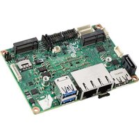

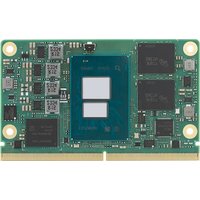
- Copyright
- Acknowledgements
- Product Warranty (2 years)
- Declaration of Conformity
- CE
- FCC Class B
- FM
- Technical Support and Assistance
- Warnings, Cautions and Notes
- Document Feedback
- Packing List
- Safety Instructions
- Safety Precaution - Static Electricity
- Chapter 1 General Information ....1
- Chapter 2 Mechanical Information ....13
- Chapter 3 AMI BIOS....19
- Chapter 4 S/W Introduction & Installation...... 59
- Appendix A Pin Assignment....63
- Appendix B Watchdog Timer 67
- Appendix C System Assignments ......69
- Chapter 1
- General Information
- Introduction
- Functional Block Diagram
- Product Specification
- Compliance
- Feature List
- Processor System
- Memory
- Graphics / Audio
- Expansion Interface
- PCIe x1
- LPC
- Serial Bus
- SMBus
- I2C Bus
- I/O
- Gigabit Ethernet
- SATA
- USB3.0/USB2.0
- USB3.0
- USB2.0
- HDA
- SPI Bus
- eMMC
- SD
- SDIO
- TXE
- SMBus
- Serial port
- MIPI
- TPM
- BIOS
- Power Management
- Power Supply
- PWROK
- Power Sequence
- Wake Event
- Advantech S5 ECO Mode (Deep Sleep Mode)
- Environment
- Temperature
- Humidity
- Vibrations
- Drop Test (Shock)
- EMC
- MTBF
- OS Support (duplicate with SW chapter)
- Advantech iManager
- Power Consumption
- Performance
- Selection Guide w/ P/N
- Packing list
- Development Board
- Optional Accessory
- Pin Description
- Chapter 2
- Mechanical Information
- Board Information
- Mechanical Drawing
- Assembly Drawing
- CPU Mechanical Drawing
- Chapter 3
- AMI BIOS
- Introduction
- Entering Setup
- Main Setup
- System time / System date
- Advanced BIOS Features Setup
- Trusted Computing
- ACPI Settings
- Embedded Controller
- Serial Port Console Redirection
- CPU Configuration
- Network Stack Configuration
- CSM Configuration
- NVMe Configuration
- SDIO Configuration
- Trusted Computing
- Security Device Support
- ACPI Settings
- Enable ACPI Auto Configuration
- Enable Hibernation
- ACPI Sleep State
- Lock Legacy Resources
- Embedded Controller
- CPU Shutdown Temperature
- Smart Fan - Carrier Board
- Backlight Enable Polarity
- Brightness PWM Polarity
- Power Saving Mode
- Serial Port 1 Configuration
- Serial Port 2 Configuration
- Hardware Monitor
- Serial Port 1 Configuration
- Serial Port
- Device Settings
- Change Settings
- Serial Port 2 Configuration
- Hardware Monitor
- Serial Port Console Redirection
- COM1
- Console Redirection
- Console Redirection Settings
- COM2
- Legacy Console Redirection
- Legacy Console Redirection Settings
- Serial Port for Out-of-Band Management/ Windows Emergency Management Services (EMS)
- CPU Configuration
- Socket 0 CPU Information
- CPU Signature
- Microcode Patch
- Max CPU Speed
- Min CPU Speed
- Processor Cores
- Intel HT Technology
- Intel VT-x Technology
- L1 Data Cache
- L1 Code Cache
- L2 Cache
- L3 Cache
- CPU Power Management
- EIST
- Turbo Mode
- Boot performance mode
- C-States
- Power Limit 1 Enable
- Network Stack Configuration
- CSM Configuration
- NVMe Configuration
- SDIO Configuration
- SDIO Access Mode
- USB Configuration
- Legacy USB Support
- XHCI Hand-off
- USB Mass Storage Driver Support
- USB transfer time-out
- Device reset time-out
- Device power-up delay
- Device power-up delay in seconds
- Platform Trust Technology
- Security Configuration
- TXE HMRFPO
- Chipset Setup
- North Bridge
- Total Memory
- Memory Slot0
- Memory Slot1
- Memory Slot2
- Memory Slot3
- Above 4GB MMIO BIOS assignment
- South Bridge
- Uncore Configuration
- IGD Configuration
- RC6(Render Standby)
- IGD - LCD Control
- NXP non-EDID Support
- Color depth and packing format
- Dual LVDS mode
- LCD Panel Type
- South Cluster Configuration
- HD-Audio Configuration
- HD-Audio Support
- PCI Express Configuration
- Compliance Mode
- LAN
- PCI Express Root Port 0
- PCI Express Root Port 1
- PCI Express Root Port 2
- PCI Express Root Port 3
- ASPM
- PCIe Speed
- SATA Drive
- Chipset-SATA Controller Configuration
- Chipset SATA
- SATA Mode Selection
- SATA Port 0
- SATA Port 1
- SCC Configuration
- USB Configuration
- xHCI Mode
- XDCI Support
- USB HW MODE AFE Comparators
- Miscellaneous Configuration
- State After G3
- Wake On Lan
- BIOS Lock
- Security Chipset
- Boot Setup
- Boot Configuration
- Setup Prompt Timeout
- Bootup NumLock State
- Quiet Boot
- Boot Option Priorities
- Boot Option #1
- Fast Boot
- Save & Exit
- Chapter 4
- S/W Introduction & Installation
- S/W Introduction
- Driver Installation
- Windows Driver Setup
- Other OS
- Advantech iManager
- Control
- Display
- Monitor
- Power Saving
- Appendix A
- Pin Assignment
- A.1 SOM-3569 Qseven R2.1 Pin Assignment
- Appendix B
- Watchdog Timer
- B.1 Programming the Watchdog Timer
- Trigger Event Note
- Appendix C
- System Assignments
- Sections include:
- C.1 System I/O Ports
- C.2 Interrupt Assignments
- C.3 1st MB Memory Map
- ADVANTECH
- www.advantech.com
Brand : Advantech
Model : SOM-3569
Category : Unknown