MED-M200 - Monitor Stand NeoMounts - Free user manual and instructions
Find the device manual for free MED-M200 NeoMounts in PDF.

User questions about MED-M200 NeoMounts
0 question about this device. Answer the ones you know or ask your own.
Ask a new question about this device
Download the instructions for your Monitor Stand in PDF format for free! Find your manual MED-M200 - NeoMounts and take your electronic device back in hand. On this page are published all the documents necessary for the use of your device. MED-M200 by NeoMounts.
USER MANUAL MED-M200 NeoMounts
Adjustment and operation p. 7
Safety notes p. 8
Maintenance p. 10
natural_image
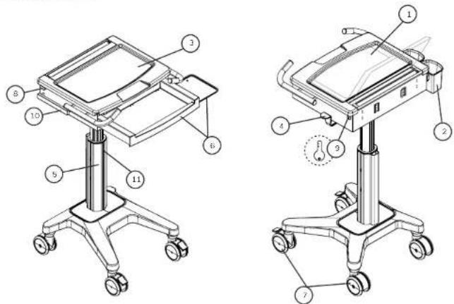
Line drawing of a medical or laboratory stand with four wheels and a central support (no text or symbols)PARTS

(x1)

[x1]

(x4)

|x2|

[Non-Text]

(x4)

|x2|

1x21

(1)

4 m

|×2|

|x2|
(x1)

5 mm (x1) (x3) (x1)


2
FEATURES
text_image
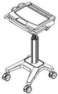
Technical diagram of a medical device with numbered components for identification and assembly reference.FEATURES
-
Laptop compartment
-
Storage basket
-
Work surface
-
Lift brake release (release brake to raise or lower the car)
-
Cable management
-
Sliding keyboard tray with mouse holder and sliding mouse tray (to accommodate both right and left hand users)
-
Casters (2 rear non-locking and 2 front locking)
-
Latch
-
Key and lock hole
-
Hanger for accessories
-
Track for accessories mounted
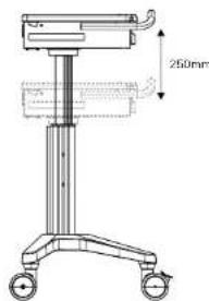
ADJUSTMENT DIRECTION
natural_image
Technical line drawing of a medical or laboratory apparatus with a 250mm height dimension label (no text or symbols beyond the dimension)natural_image
Technical line drawing of a mechanical device with wheels and a 350mm height dimension (no text or symbols beyond measurement label)3
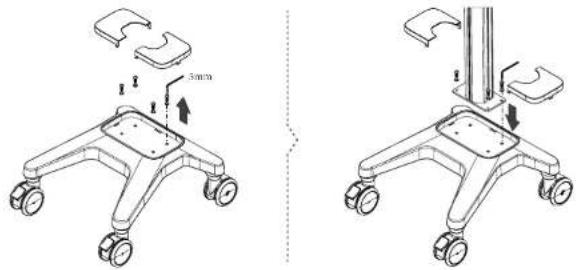
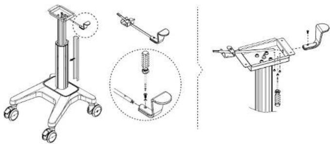
STEP 1
text_image
3mm 3mmSTEP 4
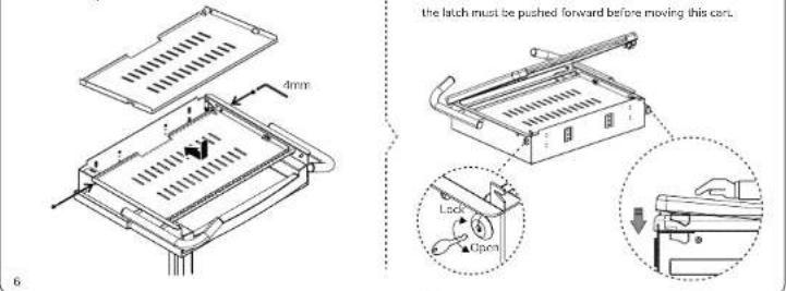
Use a 4mm Allen key to loosen the screws. Push the cooling pad forward to take it out.

text_image
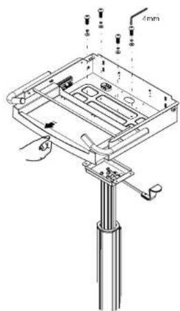
4mmUse the screws to combine the top plate and the middle pilar.
text_image
Technical diagram of a mechanical assembly with labeled parts and dimension annotation '4mm'STEP 2
natural_image
Technical line drawings of a medical or robotic device with exploded and assembled views (no text or symbols)
natural_image
Technical line drawing of a mechanical housing or enclosure with internal components and mounting holes (no text or symbols)STEP 3
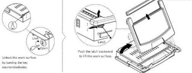
text_image
Unlock the work surface by turning the key counterclockwise. Push the latch backward to lift the work surface.STEP 6
Place the storage baskets on the side of the cart.

natural_image
Technical line drawing of a mechanical assembly with two components and a magnified inset showing internal structure (no text or symbols)Place the storage baskets at the back of the cart
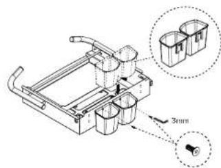
text_image
Technical diagram of a mechanical device with labeled components and a 3mm dimension annotationSTEP 7
Direction of cable management and accessory assembly.
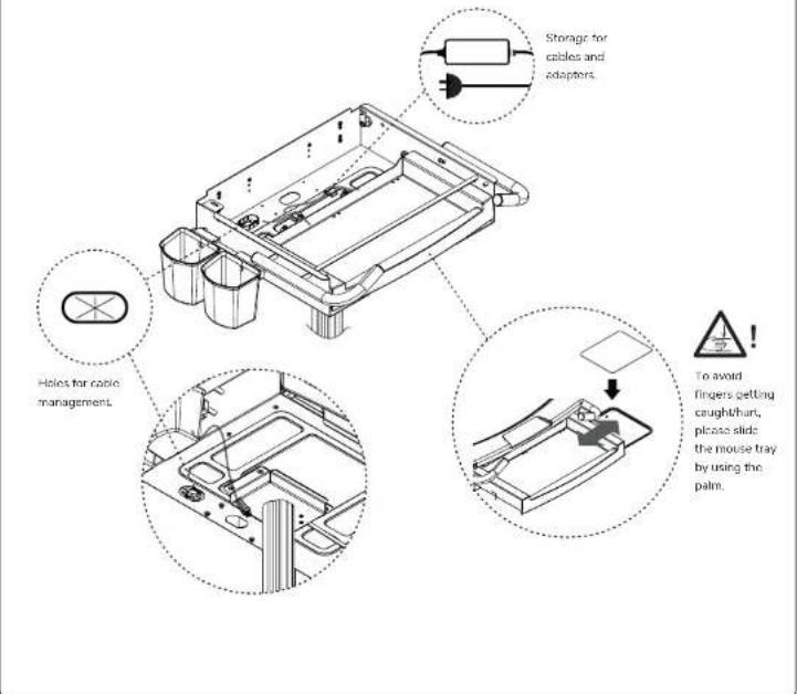
text_image
Storage for cables and adapters. Helios for cable management. To avoid fingers getting caught/hurt, please slide the mouse tray by using the palm.STEP 8
Put back the cooling pad and fasten the screws by using a Amm Alion key.
text_image
the latch must be pushed forward before moving this can. Lock OpenADJUSTMENT AND OPERATION

In case of cart damage, do not adjust the lift mechanism with an empty cart, since this may cause the work surface to rise too quickly.
Notice:
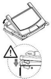
Make sure to put a hand on both sides of the work surface while releasing the brake to higher or lower the work surface, as shown in the figure. Do not push the center of the work surface to lower the height. When raising the work surface, use two hands to slightly lift the surface if it remains motionless.

text_image
250mm Release brake to adjust the height.SAFETY NOTES
WARNING
Please notice that the latch must be pushed forward after placing back the work surface.
text_image
Safety warning sign and safety instruction diagram showing no liability, warning symbol, and hazard symbol for a vehicle or equipment component.
text_image
Diagram illustrating a mechanical assembly with warning symbols and a magnified detail showing a component with a tool.WARNING
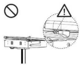
When moving the cart over irregular surface or thresholds, please lift the cart from the bottom of the keyboard compartment, as shown in the figure. Do not lift the cart from the handles.
natural_image
Illustration of a medical or laboratory apparatus with a stand and directional arrow, no text or symbols present.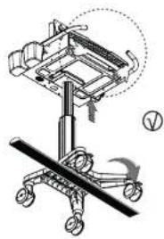
natural_image
Technical line drawing of a mechanical device with a handle and wheels, no visible text or symbolsWARNING
When the cart is in its place/not moving, make sure to put the brake on the two front casters.


natural_image
Line drawing of a mechanical device with a hand holding a knob, no text or symbols presentWARNING
Make sure to put a hand on both sides of the work surface while releasing the brake to higher or lower the work surface, as shown in the figure. Do not push the center of the work surface to lower the height. When raising the work surface, use two hands to slightly lift the surface if it remains motionless.


text_image
Height adjustment buttonWARNING
Please do not apply pressure to the work surface, especially not in the center area, except when adjusting the height.
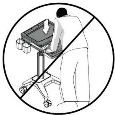
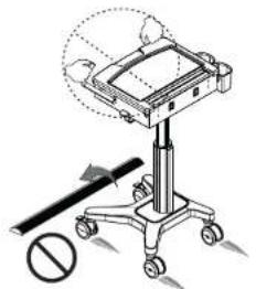
natural_image
Illustration of a person using a medical cart with a diagonal line crossing it, no text or symbols present3
9
MAINTENANCE
All cart maintenance must be carried out at least once a month by a professional technician.
Cleaning warning
Because the cart is in the environment of electrical equipment, the usage of inflammable cleansers are strictly forbidden.
- Before cleaning the cart, please make sure the cart is unplugged from the mains and switched off.
- Please ensure the cart is entirely dry before plugging the power into the socket.
- While cleaning the cart, please use a damp cloth to wipe off the superficial cleansers until completely dry.
- The car is not to be used in a moist environment and liquids have to be avoided from running into the car.
- To avoid the finishing of the surface being damaged, do not use any abrasive materials for cleaning.
- Before using any cleanser on the cart, please test them on a small part to see whether it affects the surface or not.
Please note that these guidelines give no guarantee whatsoever in terms of infection control. Kindly consult your medical infection control specialist for cleaning advice.
Cleaning recommendations
- Please use non-abrasive or diluted products such as soap water and diluted alcohol to clean the plastic components
- In case of spots of pen or maker on the cart's surface, a soft cloth with 91% isopropyl alcohol is suggested for cleaning.
- In case of iodine spots on the cart's surface, a soft cloth with soap water or diluted alcohol is suggested for cleaning.
The following chemicals are strictly forbidden for cleaning the cart: Abrasive cleansers, acetone, mineral spirits, point thinner or any other harsh or toxic chemicals.
Inspections
All cart inspections must be carried out at least once a month by a professional technician.
In case of faults or damage occurring, stop operating the cart and contact your distributor for further assistance.
Casters
To allow the cart to move as intended, please inspect the casters regularly and keep the cart away from damaged and irregular surfaces.
Fasteners
If fasteners/ screws become loose and need to be tightened, do not over tighten them. Over tightened fasteners/ screws might not only cause damage to the screws but also to the components.
Troubleshooting
The cart is difficult to move
Ensure the two front locking casters are not locked. Check if any doors is sticking to casters and remove it.
The cart is difficult to adjust in height
Ensure the lift brake is pressed completely and lift the work surface slightly, to prevent the work surface to rise too quickly. If the lift mechanism still doesn't work, please contact your distributor for further assistance. Also contact your distributor for assistance if the lift mechanism keeps going up automatically.
10
Neomounts®
BY NEWSTAR
EN ! CAUTION
- To ensure safety, please read this manual carefully before installation and follow the instructions. Store this manual in a secure place for future reference.
- The manufacturer shall not be legally responsible for any equipment damage or personal injury caused by incorrect installation or operation other than that covered in this manual.
- The mount is designed for easy installation and removal. The manufacturer shall not be liable for damage to equipment or personal injuries arising out of human factors or acts of nature, such as earthquake or typhoon.
- It is recommended that the mount be installed by qualified personnel only.
- At least two persons are needed to install or remove the product to avoid hazard of failing objects.
- Please carefully inspect the area where the mount is to be installed:
- Avoid places that are subject to high temperatures, humidity or contact with water
- Do not install the product near air conditioning vents or areas with excess dust and fumes.
- Only install on vertical walls and avoid slanted surfaces
- Do not install in places subject to any shock or vibration.
- Do not install in places subject to direct exposure to bright light, as it may cause eye fatigue when viewing the display panel.
- Maintain sufficient space around the display to ensure adequate ventilation.
- To ensure safe installation, first check the structure of the wall, ceiling or floor and select a secure mounting location.
- The wall, ceiling or floor should be strong enough to sustain a weight of at least four times of the display and mount combined. The mounting location must be able to withstand earthquake or other strong shock.
- Do not modify any accessories or use broken parts. Contact your dealer with any questions.
- Tighten all screws (do not exert excessive force to avoid breaking the screw or damaging its thread).
- Drill holes and bolts will be left in the wall, ceiling or floor once the display and bracket are removed. Stains may occur after extended use.
- Since the manufacturer has no way to control the wall, ceiling or floor type and installation of the mount, the warranty of the product shall only cover the body of the mount. The warranty period of the product is 5 years.
- Please consult the English language manual for any dispute on conditions.