FM52 - Pregnant JBL - Free user manual and instructions
Find the device manual for free FM52 JBL in PDF.

User questions about FM52 JBL
0 question about this device. Answer the ones you know or ask your own.
Ask a new question about this device
Download the instructions for your Pregnant in PDF format for free! Find your manual FM52 - JBL and take your electronic device back in hand. On this page are published all the documents necessary for the use of your device. FM52 by JBL.
USER MANUAL FM52 JBL
natural_image
White speaker chamber with black lens inside an orange circular frame (no text or symbols)FM52, FM62, FM82, FM65C & FM8SUB simple set-up guide
thank you for choosing JBL. For over 50 years, JBL has been involved in every aspect of musical and film recording and reproduction, from live performances to monitoring the recordings you play in your home, car, or office.
We're confident that the JBL loudspeakers you have chosen will provide every note of enjoyment that you expected – and that when you think about purchasing additional audio equipment for your home, car, or office you will once again choose JBL.
Please take a moment to complete the enclosed profile card. It enables us to keep you posted on our latest advancements, and helps us to better understand our customers and build products that meet your needs and expectations.
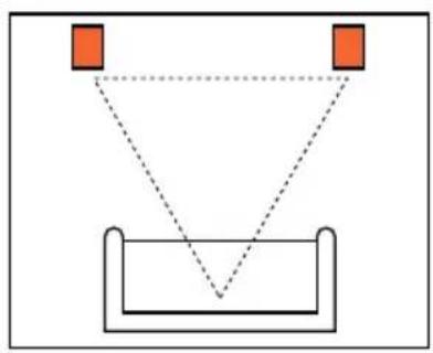
one. Speaker Placement
FM52, FM62, FM82 as front speakers
natural_image
Simple geometric diagram showing two orange squares above a V-shaped container with dashed lines indicating alignment or measurement (no text or symbols)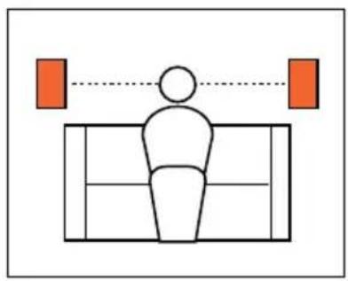
natural_image
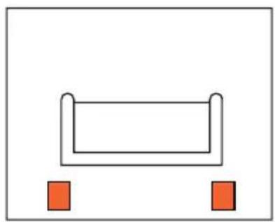
Simple line drawing of a person sitting on a bench with two orange squares above, connected by a dotted line (no text or symbols)FM52, FM62, FM82 as rear speakers
natural_image
Simple diagram of a rectangular object with two small red squares at the bottom (no text or symbols)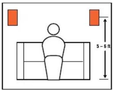
text_image
5 - 6 ftFM65C in ceiling
natural_image
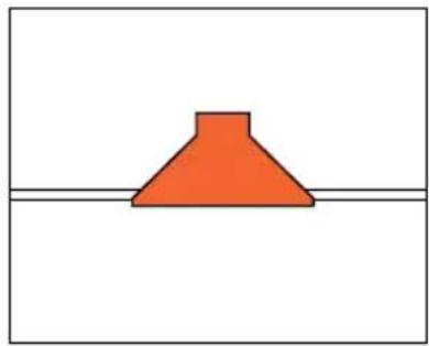
Simple diagram of a red conical shape above a horizontal line (no text or symbols)FM8SUB subwoofer in wall

natural_image
Simple diagram with three black speaker icons and a central orange square (no text or symbols)two. Speaker Connections
Connection Tips
Wire Length Recommended Size
Up to 20 ft. 16 gauge
Up to 30 ft. 12 gauge
Greater than 30 ft. 10 gauge
The wires for both speakers should be the same length. If one speaker is placed closer to the amplifier than the other, hide the excess wire behind the wall.
natural_image
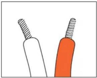
Illustration of two stylized tools with textured surfaces, one white and one orange, against a plain background (no text or symbols)Speakers and electronics terminals have corresponding (+) and (−) terminals. It is important to connect both speakers identically: (+) on the speaker to (+) on the amplifier and (−) on the speaker to (−) on the amplifier. Wiring “out of phase” results in thin sound, weak bass and a poor stereo image.
FM52, FM62, FM82, FM65C
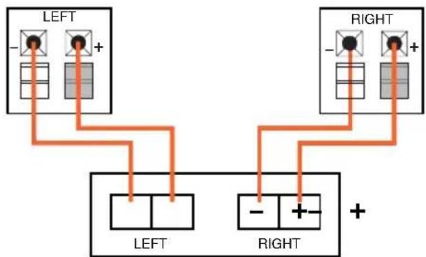
flowchart
graph TD
    A["LEFT"] --> B["+"]
    C["LEFT"] --> D["-"]
    E["RIGHT"] --> F["+"]
    G["RIGHT"] --> H["-"]
Front or Rear Speaker Outputs
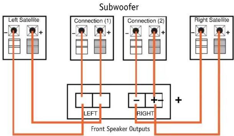
FM8SUB
The FM8SUB has two speaker connections. Connect one set of terminals, along with your left satellite to the left channel of your amplifier. Connect the other set of terminals, along
with your right satellite to the right channel of your amplifier.
flowchart
graph TD
    A["Left Satellite"] --> B["Left"]
    C["Right Satellite"] --> D["Right"]
    E["Connection (1)"] --> F["LEFT"]
    G["Connection (2)"] --> H["RIGHT"]
    I["Left Satellite"] --> J["Left"]
    K["Right Satellite"] --> L["Right"]
    M["Connection (1)"] --> N["Left"]
    O["Connection (2)"] --> P["Right"]
    Q["Left Satellite"] --> R["Left"]
    S["Right Satellite"] --> T["Right"]
    U["Left Satellite"] --> V["Left"]
    W["Right Satellite"] --> X["Right"]
    Y["Connection (1)"] --> Z["Left"]
    AA["Connection (2)"] --> AB["Right"]
    AC["Left Satellite"] --> AD["Left"]
    AE["Right Satellite"] --> AF["Right"]
    AG["Left Satellite"] --> AH["Left"]
    AI["Right Satellite"] --> AJ["Right"]
    AK["Connection (1)"] --> AL["Left"]
    AM["Connection (2)"] --> AN["Right"]
    AO["Left Satellite"] --> AP["Left"]
    AQ["Right Satellite"] --> AR["Right"]
    AS["Left Satellite"] --> AT["Left"]
    AU["Right Satellite"] --> AV["Right"]
    AW["Left Satellite"] --> AX["Left"]
    AY["Right Satellite"] --> AZ["Right"]
three. Installation
The FM Series flush-mount speakers were designed to be easily installed. However, if you are unsure of your ability to
properly install these loud-speakers, please contact your dealer or a qualified installer.
Tools Needed

Phillips #2 screwdriver
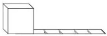
natural_image
Simple line drawing of a 3D block and a horizontal line with four equal segments (no text or symbols)Measuring tape

Utility knife

Pencil

text_image
Carpenter's levelCarpenter's level

Awl
FM52, FM62, FM82
Installation Kit
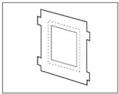
natural_image
Pure geometric diagram of a square with dashed inner lines, no text or symbols presentTemplate

natural_image
Isometric line drawing of a rectangular enclosure with mounting holes and internal compartments (no text or symbols)Speaker frame

natural_image
Illustration of multiple pointed nails arranged diagonally (no text or symbols)Thread-forming screws
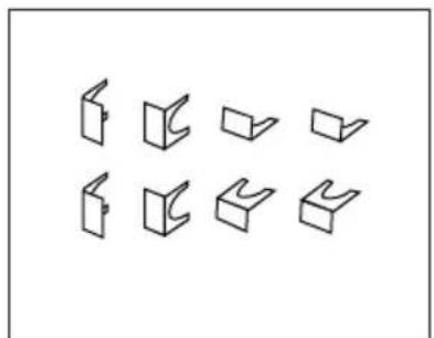
natural_image
Pure geometric diagram of nine 3D rectangular blocks arranged in two rows (no text or symbols)Retainer clips

natural_image
Technical line drawing of a rectangular plate with bolt holes and dotted pattern (no text or symbols)Mounting brackets
Existing Construction

natural_image
Technical line drawing of a mechanical component with a screwdriver inserted (no text or symbols)Step One:
Remove the grille from the speaker frame.
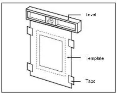
text_image
Level Template TapeStep Two:
Determine the correct speaker location.

text_image
±1-1/2" ±1-1/2" ±1-1/2"Step Three:
Determine the speaker-frame location.

natural_image
Pure technical line drawing of a mechanical component with no text or symbolsStep Four:
Cut the dry wall.
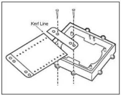
text_image
Kerf LineStep Five:
Place the mounting bracket on the speaker frame using the mounting guides (marked 3/8", 1/2", 5/8", and 3/4") corresponding to the thickness of the dry wall.
natural_image
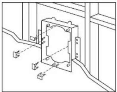
Technical line drawing of a mechanical assembly with mounting holes and wiring (no text or symbols)Step Six:
Place the frame assembly in the wall.
natural_image
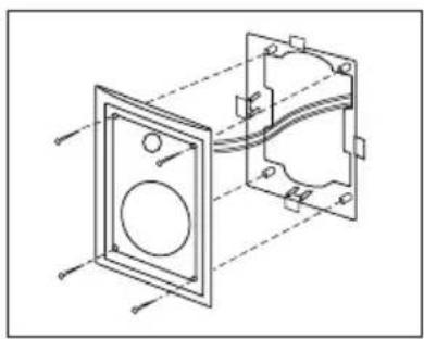
Technical line drawing of a mechanical assembly with two views (front and side), no text or symbols presentStep Seven:
Connect the speaker wires to the baffle assembly and install baffle assembly in frame.
Do not overtighten the baffle screws.

natural_image
Simple line drawing of a rectangular frame with four orange arrows pointing outward from its sides (no text or symbols)Step Eight:
Replace the metal grille.
New Construction
natural_image
Line drawing of a mechanical device with a tool inserted, showing no text or symbolsStep One:
Remove the grille from the speaker frame.

natural_image
Technical line drawing of a mechanical housing assembly with mounting holes and bolted joints (no text or symbols)Step Two:
Attach the proper mounting bracket, marked and preset at 3/8", 1/2", 5/8", and 3/4" to the speaker frame.

text_image
Ø1-1/2" Ø1-1/2"Step Three:
Determine the correct speaker location.

natural_image
Technical line drawing of a mechanical assembly with mounting brackets and alignment guides (no text or symbols)Step Four:
Nail or screw the speaker frame assembly to the wall studs and route the wires through the frame opening.
After the Drywall is Installed

natural_image
Pure technical line drawing of a mechanical component with no text or symbolsStep Five:
Cut the drywall.

natural_image
Technical line drawing of a mechanical component with mounting holes and internal features (no text or symbols)Step Six:
Connect the speaker wires to the baffle assembly and install baffle assembly in frame. Do not overtighten the baffle screws.

natural_image
Simple line drawing of a rectangular frame with four orange arrows pointing inward (no text or symbols)Step Seven:
Replace the metal grille.
FM8SUB
natural_image
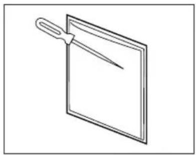
Simple line drawing of a pair of scissors placed on a blank sheet (no text or symbols)Step One:
Remove the grille from the subwoofer frame.
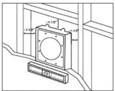
text_image
-1-1/2" ≥1-1/2"Step Two:
Determine the correct subwoofer location.
natural_image
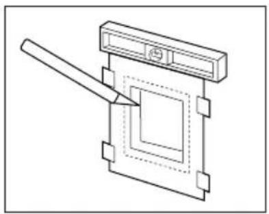
Pure technical line drawing of a mechanical component with no text or symbolsStep Three
Cut the drywall.
natural_image
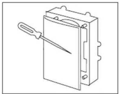
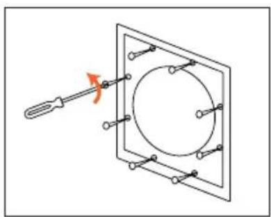
Diagram of a screwdriver inserted into a square frame with a circular component, no text or symbols presentStep Four:
Loosen the eight phillips head screws until the locking tabs turn inward.
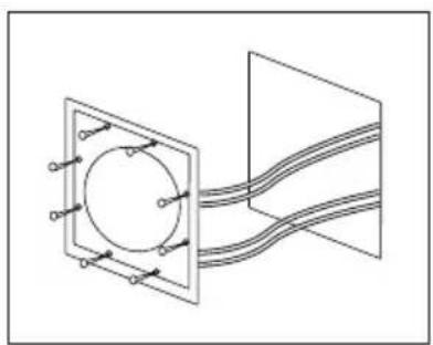
natural_image
Pure electrical circuit lines without any symbolsStep Five
Connect the speaker wires to the baffle assembly.
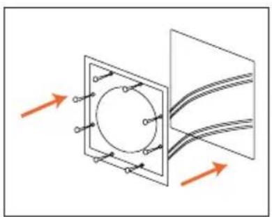
natural_image
Diagram showing a circular component inside a square frame with arrows indicating direction, no text or symbols present.Step Six:
Place the subwoofer in the wall.
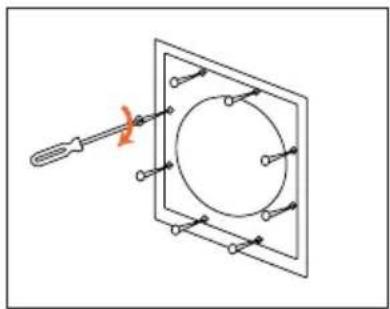
natural_image
Pure electrical circuit lines without any symbolsStep Seven:
Screw down each of the eight phillips head screws. The tabs will swivel into place and secure the unit to the rear surface of the drywall.

natural_image
Simple line drawing of a square panel with arrows indicating direction (no text or symbols)Step Eight
Replace the metal grille.
FM65CX
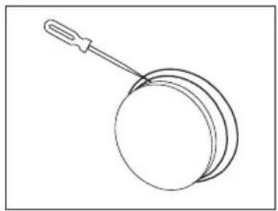
natural_image
Simple line drawing of a round object with a handle, resembling a pan or stand (no text or symbols)Step One:
Remove the grille from the speaker frame.
text_image
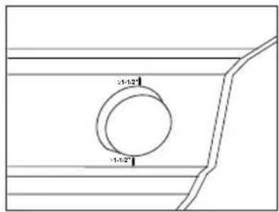
21-12" 11-12"Step Two:
Determine the correct speaker location in the ceiling.
natural_image
Pure technical line drawing of a mechanical component with no text or symbolsStep Three:
Cut the drywall.
Remove 4 phillips head screws that attach speaker to frame.
natural_image
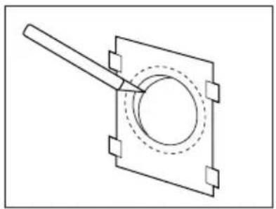
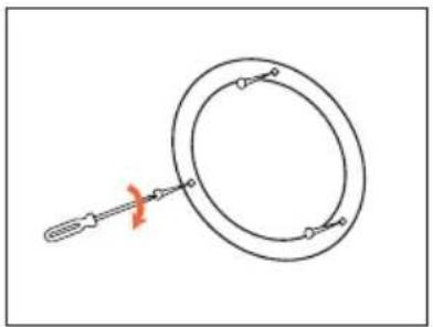
Simple line drawing of a magnifying glass with a screwdriver inserted, no text or symbols presentStep Five:
Loosen the three phillips head screws on the frame, until the locking tabs turn inward.
natural_image
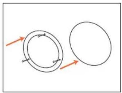
Two circular diagrams with arrows indicating direction, no text or symbols presentStep Six:
Place the frame assembly in the wall.
natural_image
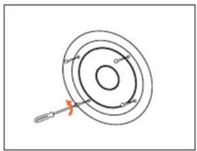
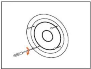
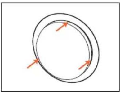
Simple line drawing of a ring with a tool, no text or symbols presentStep Seven:
Screw down each of the three phillips head screws. The tabs will swivel into place and secure the unit to the rear surface of the drywall.
natural_image
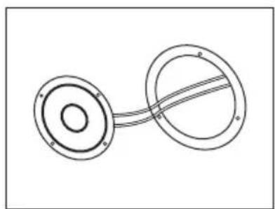
Pure mechanical diagram showing two circular components connected by a curved line (no text or symbols)Step Eight:
Connect the speaker wires to the speaker.
natural_image
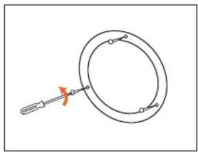
Diagram of concentric circular rings with a tool inserted, no text or symbols presentStep Nine:
Reinstall speaker in frame, using 4 phillips head screws.
natural_image
Simple diagram of two concentric circles with arrows indicating direction (no text or symbols)Step Ten:
Replace the metal grille.
Painting the Speaker Frame and Grille
FM Series loudspeakers can be painted to match any style of decor. If you wish to change their color, the satin finish on the grille and frame will function as a primer coat. Before painting install the paint guard (in the assembly kit) securely into the recess in the baffle. This will protect the speaker components and baffle from paint residue.
Use a high-quality spray paint, and apply a thin coat of color. Be certain the grille perforations remain free of paint. Filling them with paint will diminish the sound quality.
Note: Gently remove the acoustical blanket from the back of the grille before painting. Reattach the acoustical blanket after the paint has dried.
Troubleshooting
If there is no sound from either of the speakers, check the following:
- Receiver/amplifier is on and a source is playing.
- Check all wires and connections between receiver/amplifier, in-wall room volume control and speakers. Make sure all wires are connected. Make sure none of the speaker wires are frayed, cut, or punctured.
- Review proper operation of your receiver/amplifier.
If there is no sound coming from one speaker, check the following:
- Check the "Balance" control on your receiver/amplifier.
- Check all wires and connections between receiver/amplifier, and speakers. Make sure all wires are connected. Make sure none of the speaker wires are frayed, cut, or punctured.
If there is low bass output, check the following:
- Make sure the connections to the left and right "Speaker Inputs" have the correct polarity (+ and -).
If the system plays at low volumes but shuts off as volume is increased, check the following:
- Check all wires and connections between receiver/amplifier and speakers. Make sure all wires are connected. Make sure none of the speaker wires are frayed, cut, or punctured.
- If more than one pair of main speakers is being used, check the minimum impedance requirements of your receiver/amplifier.
Specifications
SYSTEM FM52 FM62 FM65C
Frequency Response (-6dB): 50Hz - 20kHz 40Hz - 20kHz 45Hz - 20kHz
Recommended Maximum
Amplifier Power*: 40 watts 50 watts 50 watts
Sensitivity: 88dB 90dB 90dB
Impedance: 8 ohms nominal 8 ohms nominal 8 ohms nominal
Crossover Frequency: 6kHz 5kHz 7kHz
Woofer: 5-1/4" 6-1/2" 6-1/2"
Tweeter: 1" titanium 1" titanium 1" titanium
Outside Dimensions (HxW): 11 x 7-1/2 inches 13 x 7-1/2 inches 8-1/8 inches (dia.)
280 × 190mm 330 × 190mm 206mm (dia.)
SYSTEM FM82 FM8SUB
Frequency Response (-6dB): 35Hz - 20kHz 32Hz - 300Hz
Recommended Maximum
Amplifier Power*: 60 watts 120 watts
Sensitivity: 88dB 88dB
Impedance: 8 ohms 8 ohms
Crossover Frequency: 5kHz 300Hz
Woofer: 8" 8"
Tweeter: 1" titanium N/A
Outside Dimensions (HxW): 15-1/8 x 11 inches 11-13/16 x 11-13/16 inches
385 x 280mm 300 x 300mm
Occasional refinements may be made to existing products without notice, but will always meet or exceed original specifications unless otherwise stated.
*The maximum recommended amplifier power rating will ensure proper system headroom to allow for occasional peaks.
We do not recommend sustained operation at these maximum power levels.
JBL
Home Entertainment
JBL Incorporated
8500 Balboa Boulevard, Northridge, CA 91329
1-800-336-4JBL (4525) (USA only)
© 1996 JBL, Incorporated.
JBL is a registered trademark of JBL, Incorporated.
Printed in USA 7/96
Part No. FMOM
harman consumer group
Declaration of Conformity

We, JBL Europe A/S
Kongevejen 194B
DK-3460 Birkerød
DENMARK
declare in own responsibility, that the products described
In this owner's manual are in compliance with technical
standards:
EN 50 081-1/1992
EN 50 082-1/3.1995

Steen Michaelsen
JBL Europe A/S
Birkerød. DENMARK. 7/96