Stadium Marine 62 - Pregnant JBL - Free user manual and instructions
Find the device manual for free Stadium Marine 62 JBL in PDF.

User questions about Stadium Marine 62 JBL
0 question about this device. Answer the ones you know or ask your own.
Ask a new question about this device
Download the instructions for your Pregnant in PDF format for free! Find your manual Stadium Marine 62 - JBL and take your electronic device back in hand. On this page are published all the documents necessary for the use of your device. Stadium Marine 62 by JBL.
USER MANUAL Stadium Marine 62 JBL
JBL STADIUM 6, STADIUM 8, AND STADIUM 10 MARINE SPEAKER

JBL Stadium 6, Stadium 8, and Stadium 10 marine speaker - Owner's Manual
Your JBL product has been designed to provide you with the performance and ease of operation you would expect from JBL.
ABOUT THE MANUAL
This manual describes general installation guidelines. However, please note that proper installation of marine audio components requires qualified experience. If you do not have the knowledge and tools to successfully perform this installation, we strongly recommend consulting an authorized JBL dealer about your installation options. Keep all instructions and sales receipts for reference.
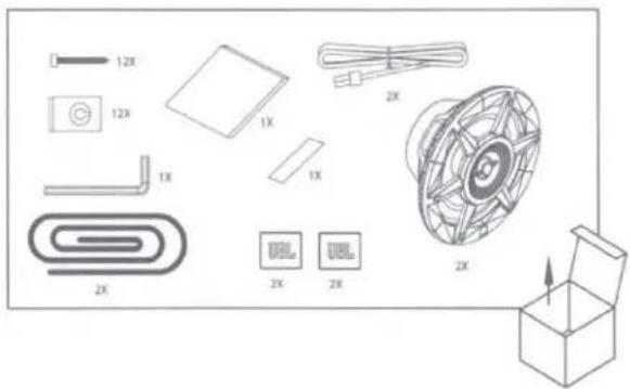
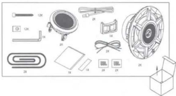
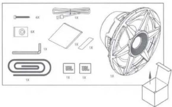
WHAT'S IN THE BOX
Stadium 6
text_image
12X 12X 1X 1X 1X 2X 2X 2X 2X 2X 2XStadium 8
text_image
12X 12X 1X 2X 1X 2X 1X 2X 2X 2XStadium 10
text_image
6X 6X 1X 1X 1X 1X 1X 1X 1X 1X 1X 1X 1X 1X 1X 1X 1X 1X 1X 1X 1X 1X 1X 1X 1X 1X 1X 1X 1X 1X 1X 1X 1X 1X 1X 1xDIMENSIONS
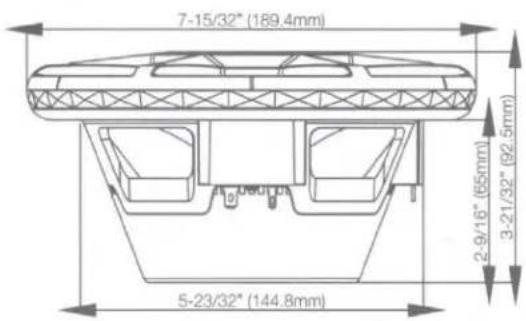
Stadium 6
text_image
7-15/32" (189.4mm) 2-9/16" (65mm) 3-21/32" (92.5mm) 5-23/32" (144.8mm)Stadium 8

text_image
9-1/2"(241.0mm) 4-5/8"(117.2mm) 3-3/16"(80.5mm) 7"(177.4mm)Stadium 10

text_image
11-5/8" (295.3mm) 6-7/6" (12.5mm) 6-9/10" (100mm) 9-9/16" (235.8mm)SPEAKER SIGNAL WIRING
To send signal to the JBL marine speaker, connect the positive (+) and negative (-) speaker wires to the appropriate speaker outputs of your source unit or amplifier. Be sure to observe proper polarity.

natural_image
Technical line drawing of a mechanical component with labeled terminals (+, RGB) and connection lines (no text or symbols beyond labels)SPEAKER LED WIRING
To provide power for the LEDs, plug the 24-gauge black (+), blue, green, and red LED wires from the speaker into the included female connector, then run the wires from the female connector to your compatible 12-volt power source or light controller (sold separately). If using a separate controller, be sure to connect each wire to the proper output.

text_image
Blue Green Red Black To power source To speakerIf hardwiring the LEDs directly to your power source, you can choose the color of the LEDs by connecting the black wire to the positive (+) terminal, and the appropriate R, G, and/or B single wire or combination of wires to the negative (-) terminal.
There are 7 possible colors, depending on the wiring configuration you choose:
| Wire connected to positive (+12V) terminal | Wire connected to negative (-) terminal | Color produced |
| Black | Red | Red |
| Green | Green | |
| Blue | Blue | |
| Red + Green | Yellow | |
| Red + Blue | Purple | |
| Blue + Green | Aquamarine | |
| Red + Blue + Green | White |
APPLYING FOAM SEAL
To help seal your installation against water, and to provide an airtight acoustic seal, apply the self-adhesive foam seal to the speaker frame.

natural_image
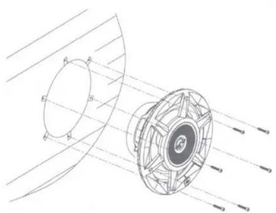
Technical line drawing of a mechanical component with a coiled spring and flange (no text or symbols)MOUNTING THE SPEAKER
Use the included screws to mount the speaker to the location. Use the included speed clips if necessary to provide a secure mount.
NOTE: Use caution when cutting and using screws with fiberglass to prevent scratches and cracks.
Stadium 6 and Stadium 8
natural_image
Technical line drawing of a mechanical component with no visible text or symbolsStadium 10
natural_image
Technical line drawing of a mechanical component with radial lines and circular features (no text or symbols)REMOVING THE TWEETER FOR SEPARATE MOUNTING (STADIUM 8 ONLY)
Use the included 2-pin tool to remove the tweeter from the woofer housing. Place the pins of the tool in the holes of the tweeter grille and rotate 45 degrees clockwise to loosen and remove.

natural_image
Technical line drawing of a mechanical component showing three sequential steps: disassembly, assembly, and final assembly (no text or symbols present)FLUSH-MOUNTING THE TWEETER
Place the tweeter in the mounting bracket and use the tool to secure by turning 45 degrees counter-clockwise.

natural_image
Three technical line drawings of a mechanical component with a 45° angle indicator (no text or symbols present)To transmit audio signal to the tweeter, make sure the woofer and tweeter are connected with the included cable.
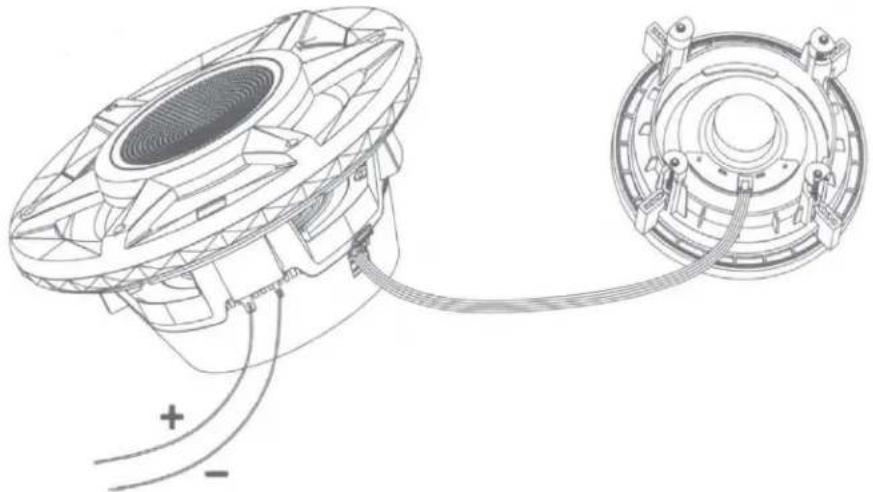
natural_image
Technical line drawing of a speaker with attached circular components and wiring (no text or symbols)EN
Place the tweeter in the mounting location, then turn each setscrew clockwise to tighten mounting brackets. Use caution so as not to overtighten. Snap the included outer ring over the mounting bracket to hide the setscrews.

natural_image
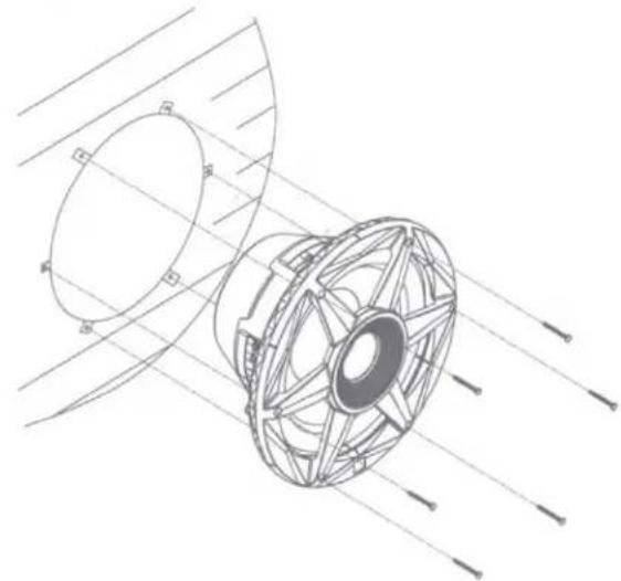
Mechanical assembly diagram showing progressive assembly of a bearing housing (no text or labels)MOUNTING IN AN ENCLOSURE (STADIUM 10 ONLY)

natural_image
Technical line drawing of a mechanical component with concentric circular features and light rays, no text or symbols presentSEALED-BOX VOLUME (INCLUDES DRIVER DISPLACEMENT)

natural_image
Technical line drawing of a mechanical assembly or enclosure with no visible text or symbolsV_BOX
| Size | Tuning frequency |
| Free air | 40Hz |
| 2 ft3 (56.6L) | 52.2Hz |
| 3 ft3 (85L) | 48.3Hz |
| 4 ft3 (113L) | 46.3Hz |
VENTED-BOX VOLUME (INCLUDES DRIVER DISPLACEMENT)

text_image
Diameter = 3-15/16" (100mm)V_BOX
| Size | Port length | Port diameter | Tuning frequency |
| 2 ft3 (56.6L) | 7-9/32" (185mm) | 3-15/16" (100mm) | 41Hz |
| 3 ft3 (85L) | 5-1/2" (140mm) | 3-15/16" (100mm) | 40.6Hz |
| 4 ft3 (113L) | 4-1/4" (108mm) | 3-15/16" (100mm) | 40.4Hz |
| TECHNICAL DATATHIELE-SMALL PARAMETERS | Stadium Marine 10"(250mm) Subwoofer 2-ohm | Stadium Marine 10"(250mm) Subwoofer 4-ohm | |
| Voice coil DC resistance: | R_EVC (OHMs) | 1.96 | 3.7 |
| Electrical inductance: | L_CES (mH) | 10.49 | 17.52 |
| Driver radiating area: | S_D (CM2) | 356.33 | 356.33 |
| Motor force factor: | B_i (TM) | 8.953 | 11.491 |
| Compliance Volume: | V_AS (Liters) | 23.5 | 23.8 |
| Suspension compliance: | C_MS (mm/N) | 0.131 | 0.133 |
| Moving mass, air load: | M_MS (Grams) | 107.338 | 106.389 |
| Moving mass, without air load: | M_MD (Grams) | 99.737 | 98.789 |
| Free-air resonance: | F_S (Hz) | 42.5 | 42.4 |
| Mechanical Q: | Q_MS | 9.913 | 4.025 |
| Electrical Q: | Q_ES | 0.699 | 0.793 |
| Total Q: | Q_TS | 0.653 | 0.663 |
| SPL, 1W/1m @ 4ohm: | Lm (dB) | 86.14 | 85.62 |
| Specifications | Stadium 6 | Stadium 8 | Stadium 10 |
| Continuous power handling | 100W | 200W | 300W |
| Peak power handling | 300W | 500W | 900W |
| Frequency response | 40Hz – 25kHz | 30Hz – 22kHz | 20Hz – 2kHz |
| Nominal impedance | 3 Ohms* | 3 Ohms* | 2 or 4 Ohms (use switch to select) |
| Sensitivity | 92dB | 92dB | 89dB |
| External diameter | 7-15/32" (189.4mm) | 9-1/2" (241mm) | 11-5/8" (295.3mm) |
| Mounting cutout diameter | 5-23/32" (144.8mm) | Woofer: 7" (177.4mm)Tweeter bracket: 4-9/16"(115.9mm) | 9-9/16" (235.6mm) |
| Total depth | 3-21/32" (92.5mm) | 4-5/8" (117.2mm) | 6-9/16" (167mm) |
| Mounting depth | 2-9/16" (65mm) | 3-3/16" (80.5mm) | 4-7/8" (123mm) |
*NOTE: Because of the woofer's low impedance, do not wire two or more in parallel to an amplifier; doing so can result in overheating and damage to the amplifier.