CBT1000E - Pregnant JBL - Free user manual and instructions
Find the device manual for free CBT1000E JBL in PDF.

User questions about CBT1000E JBL
0 question about this device. Answer the ones you know or ask your own.
Ask a new question about this device
Download the instructions for your Pregnant in PDF format for free! Find your manual CBT1000E - JBL and take your electronic device back in hand. On this page are published all the documents necessary for the use of your device. CBT1000E by JBL.
USER MANUAL CBT1000E JBL
natural_image
Line drawing of a cylindrical industrial or gas storage unit with a top lid and side panel (no text or symbols)CBT1000

natural_image
Line drawing of a cylindrical industrial or gas storage unit with mounting holes and a control panel (no text or symbols)CBT1000E
Hardware Included with CBT1000:
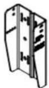
WALL BRACKETS
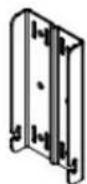
SPEAKER
BRACKETS

ARM
LINK
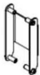

SWIVEL
BRACKETS
4 Bracket Parts for UPPER Mounting Position on Cabinet (when set for 0° or for down-tilting)

Tools Required:
M6 Hex Wrench

2 Phillips Head Screwdriver
Note: When setting system for UP tilting, the UPPER and LOWER parts get reversed on the cabinet -- see instructions.
M6 x 115 mm
PAN HEADS

M6 x 125 mm
PAN HEADS

M6 x 20 mm
OCKET HEAD

M8 x 20 mm
PAN HEADS

M6
FLAT WASHERS

M6 SPLIT
LOCK WASHERS

M6 RUBBER
WASHERS
M8
WASHERS
M8 SPLIT
CK WASHERS

M6
P NUTS

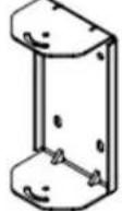
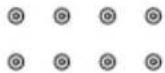
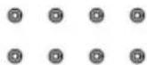
Hardware Included with CBT1000E:
natural_image
Technical line drawing of a metal bracket with mounting holes (no text or symbols)M8 x 20 mm PAN HEADS

M8 FLAT WASHERS

M8 SPLIT LOCK WASHERS

Tools Required:
2 Phillips Head Screwdriver
Instructions for CBT 1000 Alone (without 1000E):
The BRACKET ASSEMBLY consists of 2 pieces of SPEAKER BRACKETS (the parts that mount on the speaker), 2 pieces of WALL BRACKETS (the parts that mount on the wall), 2 pcs of SWIVEL BRACKETS (which get added to the SPEAKER BRACKETS if utilized for horizontal swivel/pan aiming capability), and an ARM LINK (which is utilized for the larger tilt angles).
1) RUN WIRING -- Run the wiring from the power amplifier to the location desired for mounting the JBL CBT Loudspeakers. Note: Connect wire to speaker terminals at a point in the installation process when convenient for your installation circumstances.
2) ATTACHING WALL BRACKET TO WALL -- Using a level to ensure that the WALL BRACKET is straight, secure the WALL BRACKET to the wall. Be sure to use the appropriate wall anchors for attaching the bracket. Use as many of the screw holes as possible for maximum integrity and safety.
CAUTION: Installation must be done by qualified persons using safe rigging standards.
The installer is responsible for proper selection and use of mounting hardware to properly and safely wall-mount the speakers.
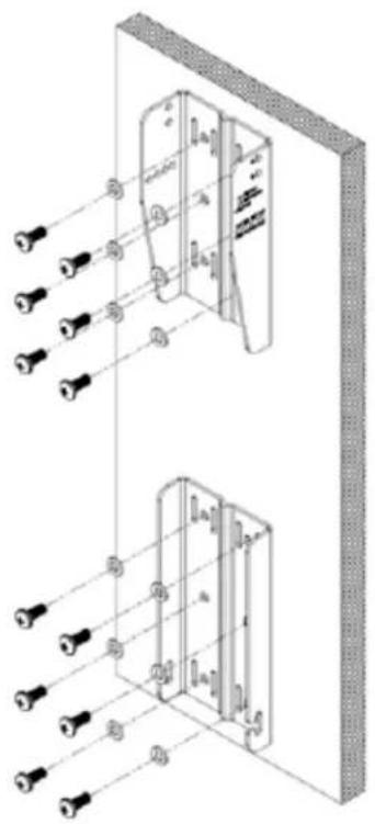
natural_image
Technical line drawing of a wall-mounted electrical enclosure with multiple lighting fixtures (no text or symbols)Hardware attaching WALL BRACKET to wall is not included. Utilize proper hardware for particular wall structure.
(Drawings show upper and lower bracket orientation as set for down-tilt or 0°. Wall brackets to be reversed in location and flipped for up-tilt applications (see further instructions).
text_image
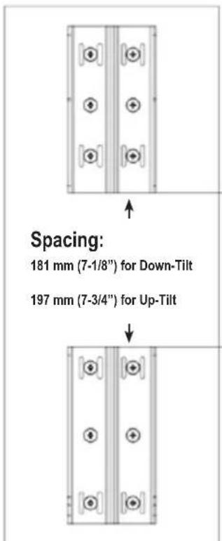
Spacing: 181 mm (7-1/8") for Down-Tilt 197 mm (7-3/4") for Up-TiltSpacing needed between upper and lower WALL BRACKET parts with CBT1000 depends on whether speaker will be set with down-tilt or up-tilt.
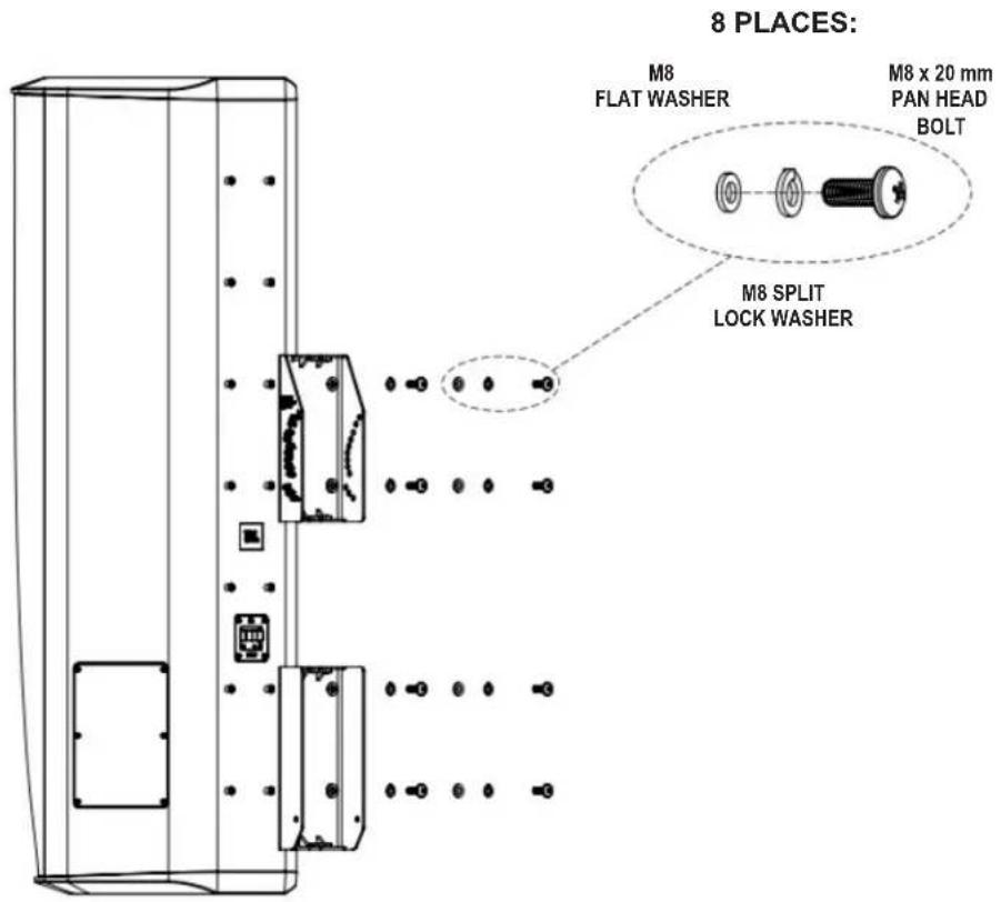
Mount the SPEAKER BRACKET (2 pcs) to the speaker with the provided M8 x20 mm pan-head bolts, in the locations shown and in the orientation shown in the diagram below.
Option 3a) CBT 1000 with No Swivel (for Down-Tilt Capability [or 0° tilt] and No Horizontal Swivel/Pan).
text_image
8 PLACES: M8 FLAT WASHER M8 x 20 mm PAN HEAD BOLT M8 SPLIT LOCK WASHERDown-tilt range 0° to -15°
Option 3b) CBT 1000 with Up-Tilt Capability -- No Horizontal Swivel/Pan
8 PLACES:

text_image
M8 FLAT WASHER M8 x 20 mm PAN HEAD BOLT M8 SPLIT LOCK WASHERUp-tilt range 0° to +15°
Option 3c) CBT1000 Mounting with Down-Tilt Capability and SWIVEL BRACKET (for Horizontal Swivel/Pan aiming capability)
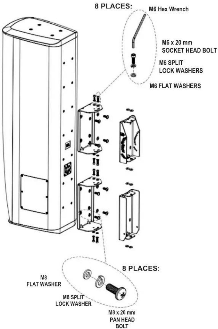
text_image
8 PLACES: M6 Hex Wrench M6 x 20 mm SOCKET HEAD BOLT M6 SPLIT LOCK WASHERS M6 FLAT WASHERS 8 PLACES: M8 FLAT WASHER M8 SPLIT LOCK WASHER M8 x 20 mm PAN HEAD BOLTDown-tilt range 0° to -15°
Option 3d) CBT1000 Mounting with Up-Tilt Capability and SWIVEL BRACKET (for Horizontal Swivel/Pan aiming capability)
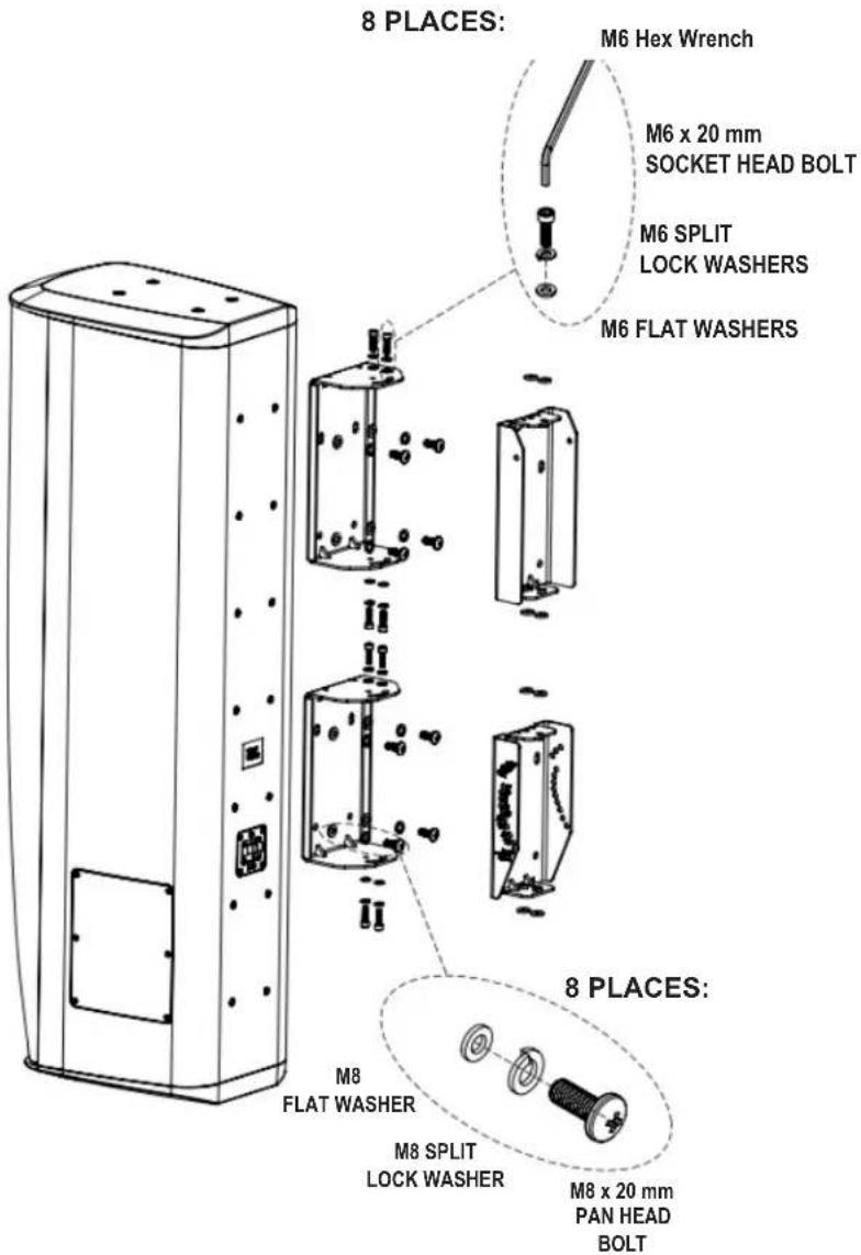
text_image
8 PLACES: M6 Hex Wrench M6 x 20 mm SOCKET HEAD BOLT M6 SPLIT LOCK WASHERS M6 FLAT WASHERS 8 PLACES: M8 FLAT WASHER M8 SPLIT LOCK WASHER M8 x 20 mm PAN HEAD BOLTUp-tilt range 0° to +15°
For Options 3c and 3d (configurations that include the SWIVEL BRACKET), place RUBBER WASHERS as shown when using SWIVEL BRACKET:
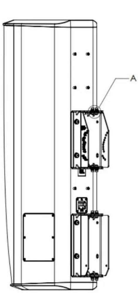
natural_image
Technical line drawing of a device casing with internal components and mounting holes (no text or symbols)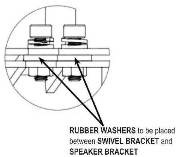
text_image
RUBBER WASHERS to be placed between SWIVEL BRACKET and SPEAKER BRACKET4) Jump to page 15 for CBT 1000 tilt angling instructions.
Instructions for CBT 1000+1000E System:
The BRACKET ASSEMBLY consists of 2 pieces of SPEAKER BRACKETS (the parts that mount on the speaker), 2 pieces of WALL BRACKETS (the parts that mount on the wall), 2 pcs of SWIVEL BRACKETS (which get added to the SPEAKER BRACKETS if utilized for horizontal swivel/pan aiming capability), and an ARM LINK (which is utilized for the larger tilt angles).
1) RUN WIRING -- Run the wiring from the power amplifier to the location desired for mounting the JBL CBT Loudspeakers. Note: Connect wire to speaker terminals at a point in the installation process when convenient for your installation circumstances.
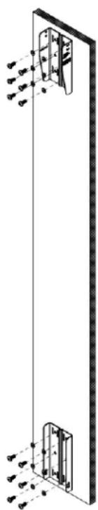
2) ATTACHING WALL BRACKET TO WALL -- Using a level to ensure that the WALL BRACKET is straight, secure the WALL BRACKET to the wall. Be sure to use the appropriate wall anchors for attaching the bracket. Use as many of the screw holes as possible for maximum integrity and safety.
CAUTION: Installation must be done by qualified persons using safe rigging standards.
The installer is responsible for proper selection and use of mounting hardware to properly and safely wall-mount the speakers.
(Drawings show upper and lower bracket orientation as set for down-tilt or 0°. Wall brackets to be reversed in location and flipped for up-tilt applications (see further instructions).
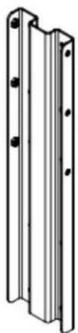
natural_image
Technical diagram of a vertical panel assembly with mounting holes and internal components (no text or labels)Hardware attaching WALL BRACKET to wall is not included. Utilize proper hardware for particular wall structure.
text_image
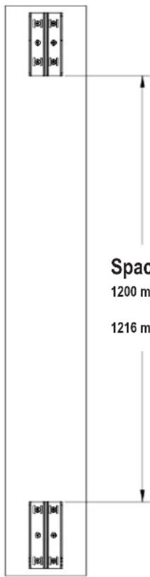
Space 1200 m 1216 mSpacing:
1200 mm (47-1/4") for Down-Tilt
1216 mm (47-7/8") for Up-Tilt
Spacing needed between upper and lower WALL BRACKET parts with CBT1000 and CBT1000E depends on whether speaker will be set with down-tilt or up-tilt
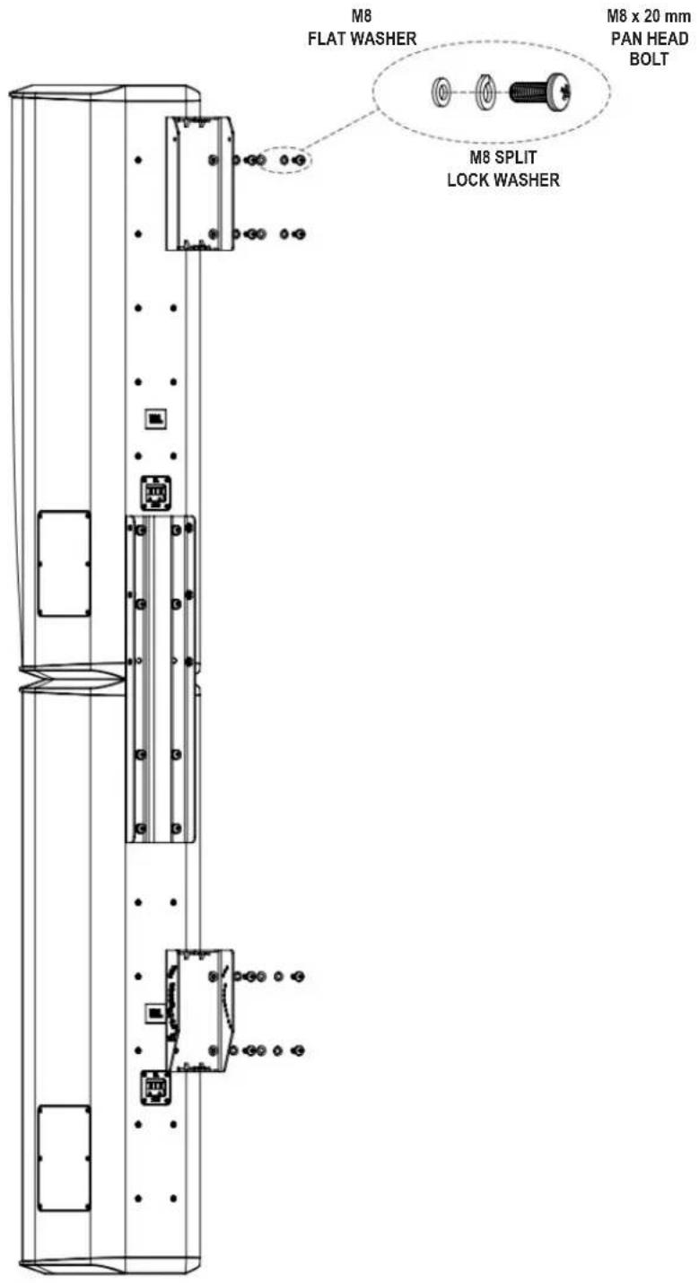
3) ATTACHING COUPLER PLATE -- Connect the CBT 1000 and CBT 1000E together by attaching COUPLER PLATE to bottom four (4) insert points of the CBT 1000 and to top four (4) insert points of CBT 1000E using 8 pcs M8 x 20 PAN-HEAD PHILLIPS BOLTS with LOCK WASHERS and FLAT WASHERS. Tighten.
IMPORTANT: WHEN THE CBT 1000E IS LOCATED ON THE TOP VERSUS ON THE BOTTOM
The diagram below shows the COUPLER PLATE attachment method for when the CBT 1000 is on the top and the CBT 1000E on the bottom. For utilizing with the CBT 1000E on top and the CBT 1000 on the bottom, the depth of the cabinets are different at the junction between them, so it is necessary to use the optional MTC-CBT-OS3 Offset Bracket (which is part of the CBT1K-ACC1 kit). See Appendix A for attaching together in this orientation utilizing the MTC-CBT-OS3 bracket.

text_image
8 PLACES: M8 FLAT WASHER M8 x 20 mm PAN HEAD BOLT M8 SPLIT LOCK WASHER Hint: One strategy for orient attaching the COUPLER PL both speakers on a non-scr surface on their sides.Hint: One strategy for orienting speakers for attaching the COUPLER PLATE is to place both speakers on a non-scratching floor surface on their sides.
(for Down-Tilt Capability [or 0° tilt] and No Horizontal Swivel/Pan)
8 PLACES:

text_image
M8 FLAT WASHER M8 x 20 mm PAN HEAD BOLT M8 SPLIT LOCK WASHERDown-tilt range 0° to -5.25°
Option 4b) CBT1000+1000E System with Up-Tilt Capability
(No Horizontal Swivel/Pan)
8 PLACES:
text_image
M8 FLAT WASHER M8 x 20 mm PAN HEAD BOLT M8 SPLIT LOCK WASHERUp-tilt range 0° to +5.25°
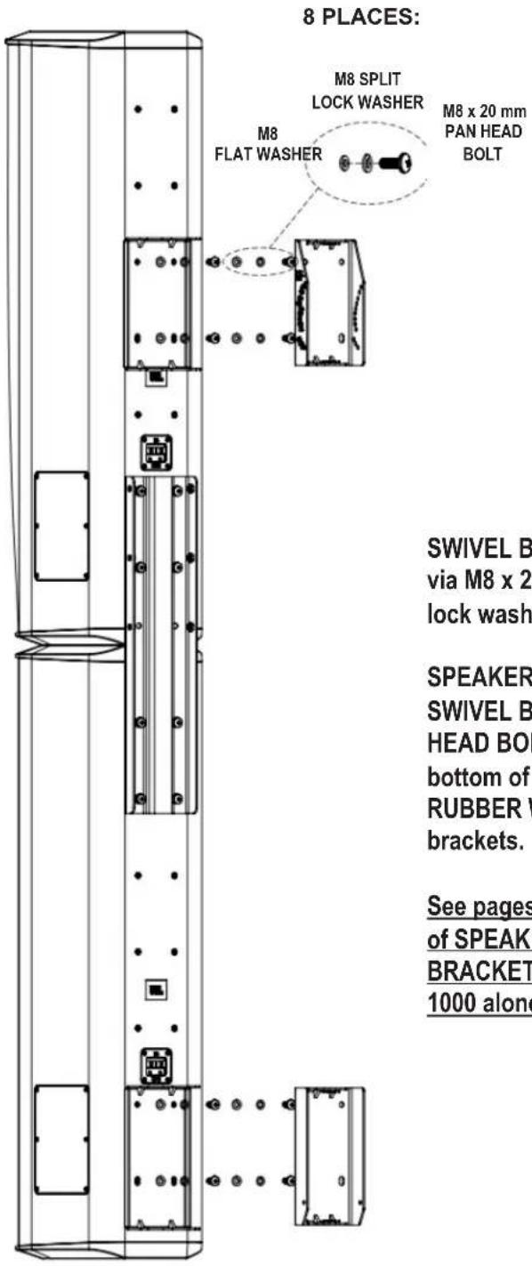
Option 4c) CBT1000+1000E System with Down-Tilt Capability and Horizontal Swivel/Pan
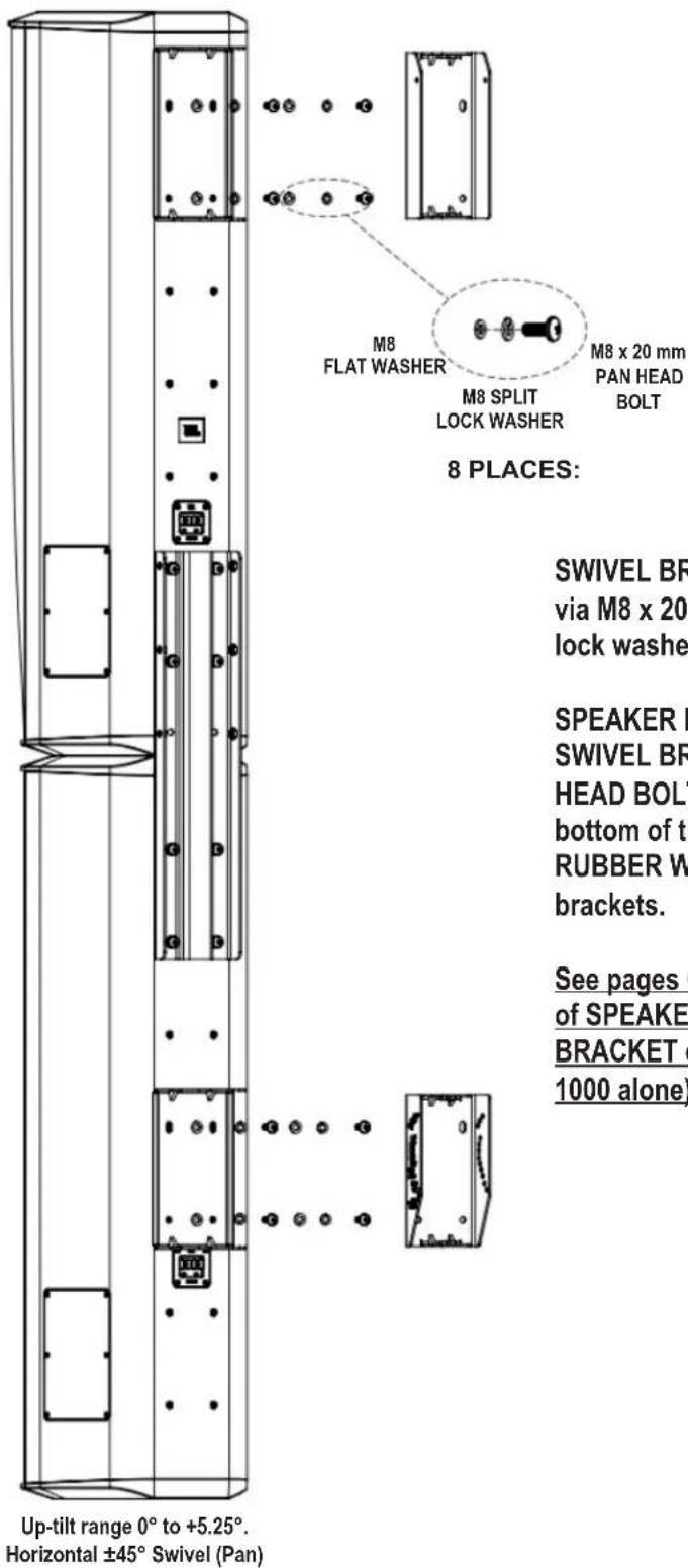
text_image
8 PLACES: M8 SPLIT LOCK WASHER M8 x 20 mm PAN HEAD BOLT M8 FLAT WASHER SWIVEL B via M8 x 2 lock wash SPEAKER SWIVEL B HEAD BOI bottom of RUBBER V brackets. See pages of SPEAKI BRACKET 1000 aloneDown-tilt range 0° to -5.25°. Horizontal ±45° Swivel (Pan)
SWIVEL BRACKET attaches to speaker via M8 x 20 mm PAN HEAD BOLTS (with lock washers and flatwashers).
SPEAKER BRACKET attaches to SWIVEL BRACKET via M6 x 20 SOCKET HEAD BOLTS inserted from the top and bottom of the SWIVEL BRACKET, with RUBBER WASHERS between the two brackets.
See pages 6 and 7 for detailed drawings of SPEAKER BRACKET / SWIVEL BRACKET connection (as shown on CBT 1000 alone).
Option 4d) CBT1000+1000E System with Up-Tilt Capability and Horizontal Swivel/Pan
text_image
M8 FLAT WASHER M8 SPLIT LOCK WASHER M8 x 20 mm PAN HEAD BOLT 8 PLACES: SWIVEL BR via M8 x 20 lock washe SPEAKER B SWIVEL BR HEAD BOLT bottom of th RUBBER W brackets. See pages ( of SPEAKE BRACKET ( 1000 alone) Up-tilt range 0° to +5.25°. Horizontal ±45° Swivel (Pan)SWIVEL BRACKET attaches to speaker via M8 x 20 mm PAN HEAD BOLTS (with lock washers and flatwashers).
SPEAKER BRACKET attaches to SWIVEL BRACKET via M6 x 20 SOCKET HEAD BOLTS inserted from the top and bottom of the SWIVEL BRACKET, with RUBBER WASHERS between the two brackets.
See pages 6 and 7 for detailed drawings of SPEAKER BRACKET / SWIVEL BRACKET connection (as shown on CBT 1000 alone).
The following instructions apply to both the CBT1000 by itself and to the CBT 1000+1000E System.
(For simplicity, drawings are shown with CBT1000 only.)
Make sure the PIVOT BOLT is installed in-place in the SPEAKER BRACKET. The PIVOT BOLT ASSEMBLY consists of the M6 x 125 mm bolt with lock washer and flat washer on the head and secured in place with flat washer, lock washer and M6 cap nut. IMPORTANT: Leave the nut loose (do not tighten).
Slide the speaker forward so that the SPEAKER BRACKET engages into the WALL BRACKET, dropping the PIVOT BOLT ASSEMBLY into the hook slot of the WALL BRACKET.
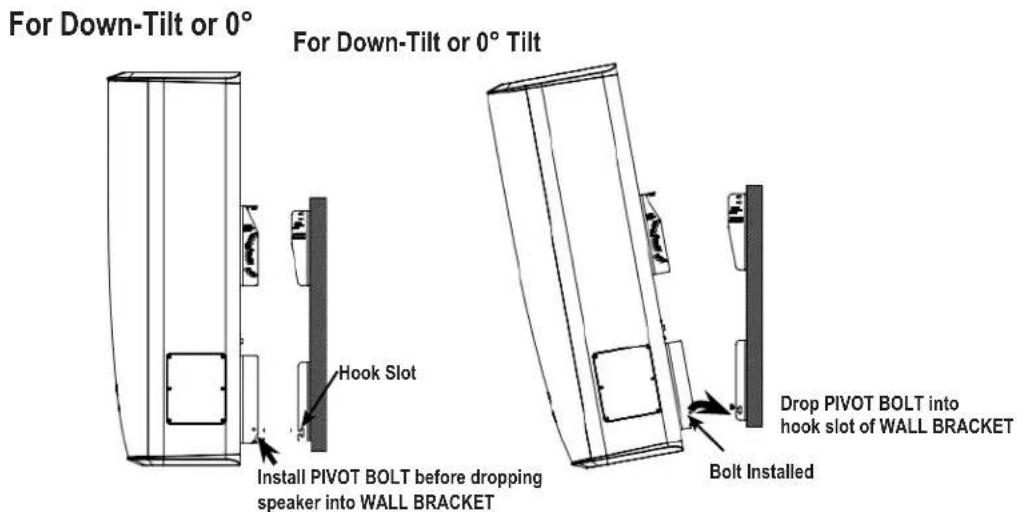
text_image
For Down-Tilt or 0° For Down-Tilt or 0° Tilt Hook Slot Install PIVOT BOLT before dropping speaker into WALL BRACKET Drop PIVOT BOLT into hook slot of WALL BRACKET Bolt Installed
text_image
For Up-Tilt Install PIVOT BOLT before dropping speaker into WALL BRACKET Hook Slot Bolt Installed Drop PIVOT BOLT into hook slot of WALL BRACKET6) SET THE TILT ANGLE
6a) For Setting Shallow Tilt Angles (0° to -3° for CBT1000; 0° to -0.9° for CBT1000+1000E System), do NOT use ARM LINK.
Slide the M6 x 125 mm BOLT into labeled hole for desired down-tilt angle. Use LOCK WASHER and FLAT WASHER on head and FLATWASHER, LOCK WASHER, and CAP NUT on end of bolt.
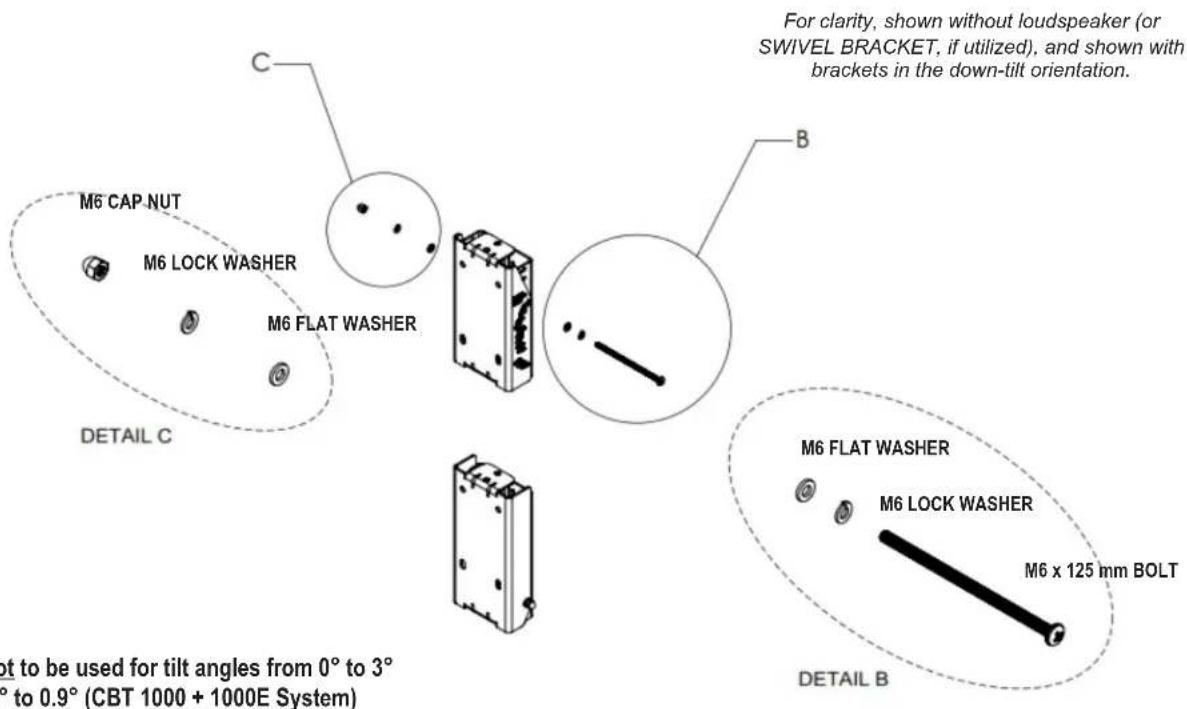
text_image
M6 CAP NUT M6 LOCK WASHER M6 FLAT WASHER DETAIL C C B For clarity, shown without loudspeaker (or SWIVEL BRACKET, if utilized), and shown with brackets in the down-tilt orientation. M6 FLAT WASHER M6 LOCK WASHER M6 x 125 mm BOLT DETAIL B not to be used for tilt angles from 0° to 3° ° to 0.9° (CBT 1000 + 1000E System)ARM LINK is not to be used for tilt angles from 0° to 3° (CBT1000) or 0° to 0.9° (CBT 1000 + 1000E System)
See full size Tilt Angle Settings Diagram for detail of markings and settings

text_image
Diagram showing a vertical layout with circular elements and directional arrows, possibly representing a layout or process with labeled components.CBT 1000: 0° CBT 1000 + 1000E: 0° Use Points "C"

text_image
Diagram showing a vertical structure with circular elements and labeled points, possibly representing a mechanical or structural component.CBT 1000: 1^ CBT 1000 + 1000E: 0.3^

text_image
Diagram showing a mechanical or electrical component with labeled parts and directional arrows indicating flow or movement.CBT 1000: 2^ CBT 1000 + 1000E: 0.6^

text_image
Diagram showing a mechanical or electrical component with labeled parts and symbols, possibly indicating a system or assembly.CBT 1000: 3^ CBT 1000 + 1000E: 0.9^
6b) For Setting Larger Tilt Angles (-4° to -15° for CBT1000; -1.25° to -5.25° for CBT1000+E System), Use ARM LINK.
Loosely attach the ARM LINK to the WALL BRACKET using the M6 x 115 mm bolt in hole A or B (depending on desired tilt angle -- refer to TILT ANGLE SETTINGS DIAGRAM). Use LOCK WASHER and FLAT WASHER on head and FLATWASHER, LOCK WASHER, and CAP NUT on end of bolt.
IMPORTANT: Do not tighten yet (leave loose).
Attach the other end of ARM LINK to SPEAKER BRACKET. Slide the M6 x 125 mm BOLT into labeled hole for desired down-tilt angle through the holes in the lower end of the ARM LINK. Use LOCK WASHER and FLAT WASHER on head and FLATWASHER, LOCK WASHER, and CAP NUT on end of bolt.
Tighten all bolts.
For clarity, shown without SPEAKER BRACKET (and SWIVEL BRACKET, if used), and shown with brackets in the down-tilt orientation.

text_image
M6 x 115 mm BOLT DETAIL F M6 LOCK WASHER M6 FLAT WASHER F G M6 x 125 mm BOLT M6 LOCK WASHER M6 FLAT WASHER DETAIL G DETAIL D M6 FLAT WASHER M6 LOCK WASHER M6 CAP NUTARM LINK is to be used for tilt angles greater than 3^ (CBT 1000) or 0.9^ (CBT 1000 + 1000E System). ARM LINK is to be installed to WALL BRACKET first before setting angle.
Tilt Angle Settings Diagram
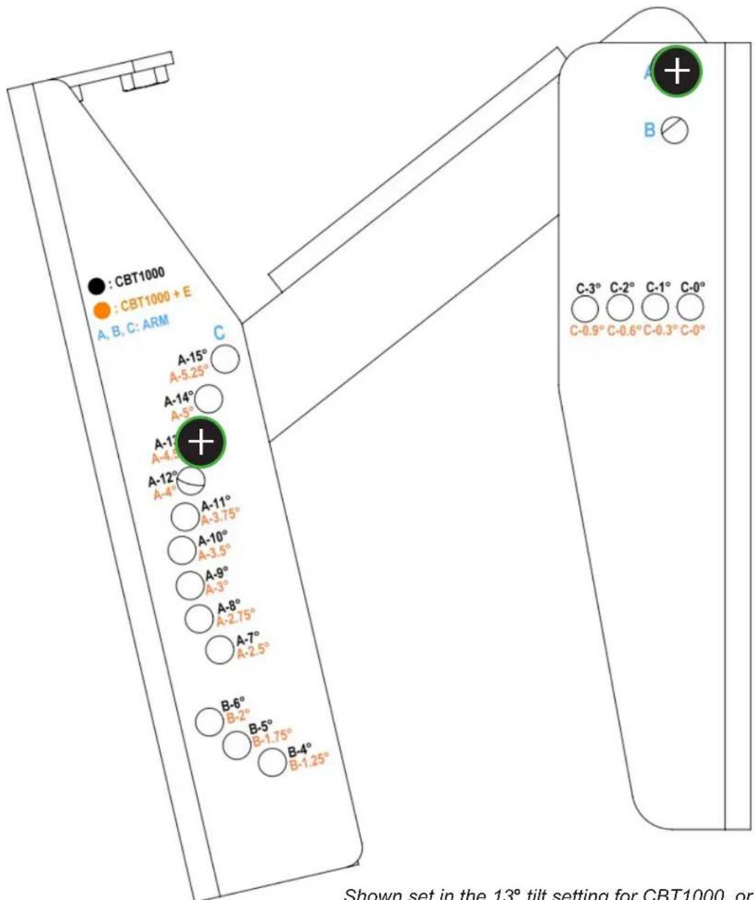
text_image
: CBT1000 : CBT1000 + E A, B, C: ARM A-15° A-5.25° A-14° A-5° A-17° A-4.5° A-12° A-4° A-11° A-3.75° A-10° A-3.5° A-9° A-3° A-8° A-2.75° A-7° A-2.5° B-6° B-2° B-5° B-1.75° B-4° B-1.25° C C-3° C-2° C-1° C-0° C-0.9° C-0.6° C-0.3° C-0° Shown set in the 13° tilt setting for CBT1000, orShown set in the 13° tilt setting for CBT1000, or 4.5° tilt setting for CBT 1000 + 1000E System (Marked A-13° in black and A-4.5° in orange, so other end of LINK ARM is at Point "A")
See full size Tilt Angle Settings Diagram on previous page for detail of markings and settings
ARM LINK Not Utilized

text_image
Use Point "C" CBT 1000: 0° System: 0°“System” = CBT 1000 + 1000E

text_image
CBT 1000: 1° System: 0.3°
text_image
CBT 1000: 2° System: 0.6°- = Bolt Setting Location(s)
text_image
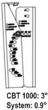
CBT 1000: 3° System: 0.9°- = Bolt Setting Location(s)
ARM LINK Utilized
“System” = CBT 1000 + 1000E

text_image
Use Point "B" CBT 1000: 4° System: 1.25° CBT 1000: 5° System: 1.75° CBT 1000: 6° System: 2.0°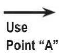

text_image
CBT 1000: 7° System: 2.5°
text_image
CBT 1000: 8° System: 2.75°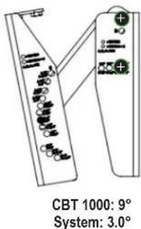
text_image
CBT 1000: 9° System: 3.0°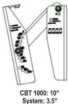
text_image
CBT 1000: 10° System: 3.5°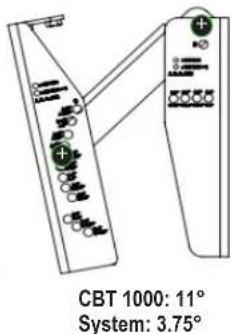
text_image
CBT 1000: 11° System: 3.75°
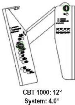
text_image
CBT 1000: 12° System: 4.0°
text_image
CBT 1000: 13° System: 4.5°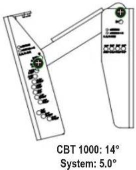
text_image
CBT 1000: 14° System: 5.0°
text_image
CBT 1000: 15° System: 5.25°7) SETTING HORIZONTAL SWIVEL (PAN) AIMING – With the 8 M6 x 20 mm SOCKET HEAD swivel screws loose (4 on top bracket and 4 on bottom bracket), set the horizontal swivel (pan) aiming angle. Tighten all 8 swivel screws.
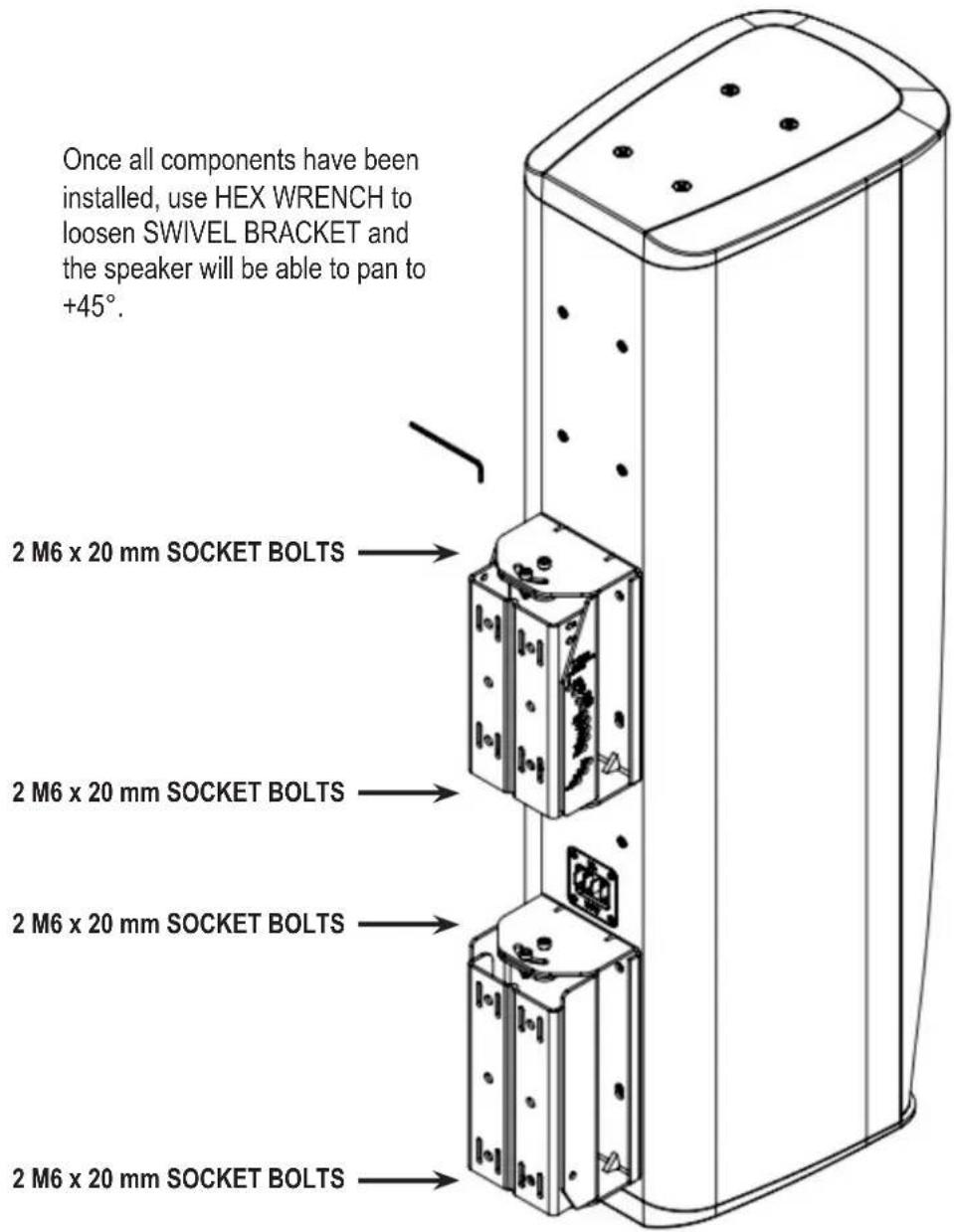
text_image
Once all components have been installed, use HEX WRENCH to loosen SWIVEL BRACKET and the speaker will be able to pan to +45°. 2 M6 x 20 mm SOCKET BOLTS 2 M6 x 20 mm SOCKET BOLTS 2 M6 x 20 mm SOCKET BOLTS 2 M6 x 20 mm SOCKET BOLTSBRACKET PARTS DIMENSIONAL DIAGRAMS
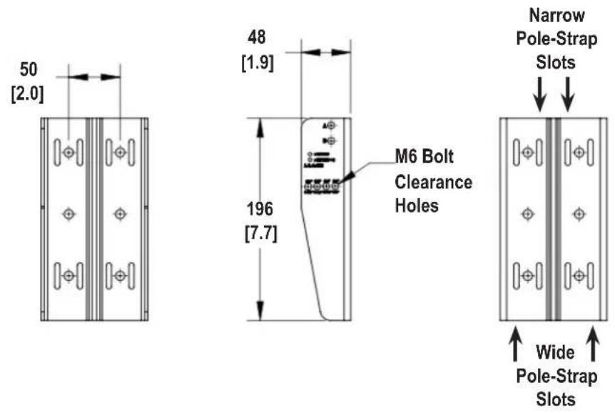
WALL BRACKET TOP/BOTTOM SECTIONS
text_image
50 [2.0] 48 [1.9] 196 [7.7] M6 Bolt Clearance Holes Narrow Pole-Strap Slots Wide Pole-Strap Slots
text_image
50 [2.0] 184 [7.3] 104 [4.1] 24 [1.0]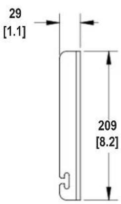
text_image
29 [1.1] 209 [8.2]
text_image
Center Recessed Channel for Improved Pole-Mount StabilityDims in mm [in]
SPEAKER BRACKET TOP/BOTTOM SECTIONS
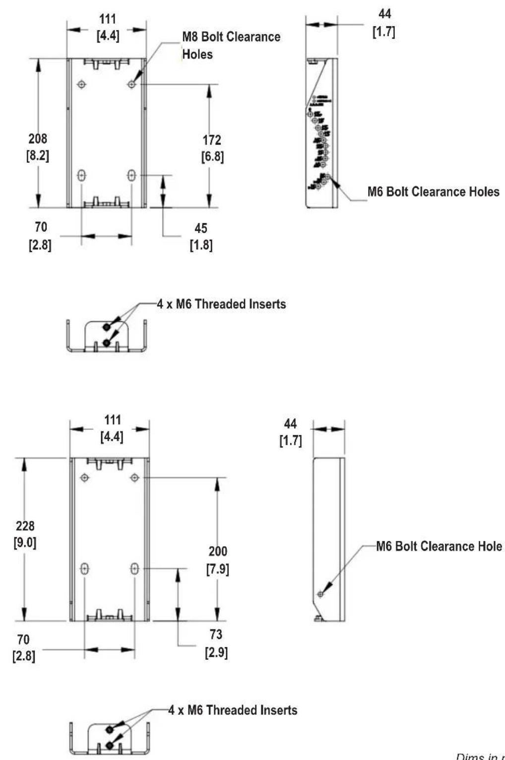
Dims in mm [in]
SWIVEL BRACKET TOP/BOTTOM SECTIONS

text_image
70 [2.8] 220 [8.7] 180 [7.1] 53
text_image
87 [3.4]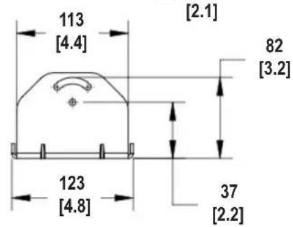
text_image
113 [4.4] [2.1] 82 [3.2] 123 [4.8] 37 [2.2]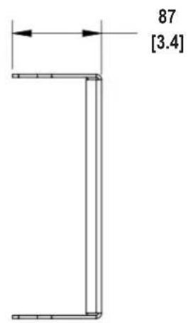
text_image
87 [3.4]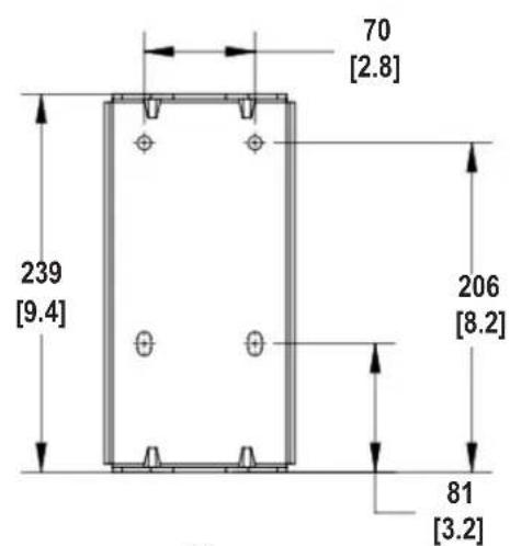
text_image
70 [2.8] 239 [9.4] 206 [8.2] 81 [3.2]
text_image
110 [4.3] 82 [3.2] 120 [4.7] 57 [2.2]Dims in mm [in]
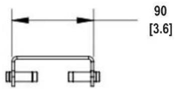
LINK ARM
text_image
90 [3.6]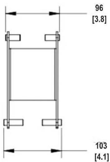
text_image
96 [3.8] 103 [4.1]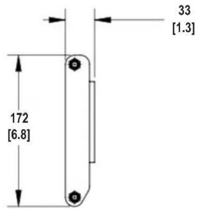
text_image
172 [6.8] 33 [1.3]APPENDIX A - MTC-CBT-OS2 Offset Bracket
MTC-CBT-OS3 Offset Bracket must be used when the CBT 1000E (extender) is located on the top versus on the bottom of the CBT 1000 (full-range speaker).
The optional MTC-CBT-OS3 bracket is part of the CBT1K-ACC1 kit.
Hardware Included with MTC-CBT-OS3:
MTC-
CBT-OS3
BRACKET

natural_image
Technical line drawing of a metal bracket with mounting holes and mounting holes (no text or symbols)M8 x 20 mm
PAN HEAD
BOLTS

M6
FLAT WASHERS

M6 SPLIT
LOCK WASHERS

Tool Required:

2 Phillips Head
Screwdriver
1) Attach MTC-CBT-OS3 to bottom 4 inserts of CBT 1000E using M8 PAN HEAD BOLTS with LOCKWASHERS AND FLATWASHERS
2) Attach top of COUPLER PLATE to MTC-CBT-OS3 BRACKET by inserting bolts through holes in MTC-CBT-OS3 BRACKET (3 on left side; 3 on right side) and thread into captured nuts in COUPLER PLATE (6 places)
3) Attach bottom of COUPLER PLATE to CBT 1000 via the normal method, using M8 PAN HEAD BOLTS with LOCK WASHERS and FLAT WASHERS (4 places)
4) Insert 2 bolts through middle holes in the back panel of the COUPLER PLATE and thread into captured nuts at the bottom of MTC-CBT-OS3 bracket.
Make sure all bolts are tight.
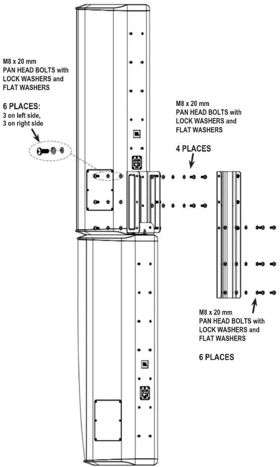
text_image
M8 x 20 mm PAN HEAD BOLTS with LOCK WASHERS and FLAT WASHERS 6 PLACES: 3 on left side, 3 on right side M8 x 20 mm PAN HEAD BOLTS with LOCK WASHERS and FLAT WASHERS 4 PLACES M8 x 20 mm PAN HEAD BOLTS with LOCK WASHERS and FLAT WASHERS 6 PLACES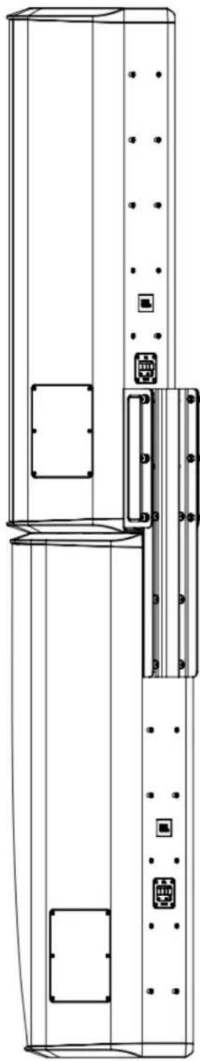
natural_image
Technical line drawing of a vertical cabinet or elevator shaft with mounting holes and control panel (no text or symbols)Completed Assembly

by HARMAN
JBL Professional
8500 Balboa Blvd.
Northridge, CA 91329
U.S.A.
CBT1000 Brkt RevC
10/17