
EI-52-S2A1 - Unknown Advantech - Free user manual and instructions
Find the device manual for free EI-52-S2A1 Advantech in PDF.

| Product Type | Embedded Industrial Computer |
| Brand | Advantech |
| Model | EI-52-S2A1 |
| Dimensions (approx.) | 200 x 150 x 40 mm |
| Weight (approx.) | 1.0 kg |
| Power Supply | 24 V DC, 2.5 A min, UL certified adapter (FSP060-DAAN2) |
| Battery | Real-time clock battery (CR2032 or equivalent) |
| Operating Temperature | 0 °C to 60 °C |
| Storage Temperature | -40 °C to 85 °C |
| Humidity | Avoid humidity, do not expose to liquids |
| Noise Level | ≤ 70 dB (A) at operator position |
| Certifications | IEC 704-1, UL for power adapter |
| Main Functions | Embedded computing, real-time clock, connectivity (ports not specified) |
| Maintenance and Cleaning | Unplug before cleaning; use a damp cloth, no liquid detergent |
| Safety Instructions | Do not cover openings, avoid drops, do not open, use original components |
| Spare Parts and Repairability | Contact a qualified technician; replace battery only with same type |
| General Information | Install in restricted access area; unplug if not used for a long time |
Frequently Asked Questions - EI-52-S2A1 Advantech
User questions about EI-52-S2A1 Advantech
0 question about this device. Answer the ones you know or ask your own.
Ask a new question about this device
Download the instructions for your Unknown in PDF format for free! Find your manual EI-52-S2A1 - Advantech and take your electronic device back in hand. On this page are published all the documents necessary for the use of your device. EI-52-S2A1 by Advantech.
USER MANUAL EI-52-S2A1 Advantech
natural_image
Illustration of four electronic circuit boards with white outlines on a purple background, no text or symbols present.EI-52
Fanless Edge Intelligence System
Attention!
This product contains a hard copy of the Chinese user manual for China CCC certification purposes. A PDF of the English user manual is included on the accompanying CD. Please disregard the hard copy Chinese user manual if the product is not sold and/or installed in China.
Copyright
The documentation and the software included with this product are copyrighted 2021 by Advantech Co., Ltd. All rights are reserved. Advantech Co., Ltd. reserves the right to improve the products described in this manual at any time without notice. No part of this manual may be reproduced, copied, translated, or transmitted in any form or by any means without the prior written permission of Advantech Co., Ltd. The information provided in this manual is intended to be accurate and reliable. However, Advantech Co., Ltd. assumes no responsibility for its use, nor for any infringements on the rights of third parties that may result from its use.
Acknowledgments
Award is a trademark of Award Software International, Inc
VIA is a trademark of VIA Technologies, Inc
IBM, PC/AT, PS/2 and VGA are trademarks of International Business Machines Corporation
Intel® and Pentium® are trademarks of Intel Corporation
Microsoft Windows® is a registered trademark of Microsoft Corp
RTL is a trademark of Realtek Semi-Conductor Co., Ltd
ESS is a trademark of ESS Technology, Inc
UMC is a trademark of United Microelectronics Corporation
SMI is a trademark of Silicon Motion, Inc
Creative is a trademark of Creative Technology LTD
CHRONTEL is a trademark of Chronel Inc
All other product names or trademarks are properties of their respective owners
For more information about this or other Advantech products, visit our website at http://www.advantech.com/
https://www.advantech.com/products/fanless-embedded-computers/sub_1-2jkeuf
For technical support and customer service, visit our support website at http://support.advantech.com.tw/support/
Part No. 2006005210 Edition 1
Printed in China August 2021
Product Warranty (2 Years)
Advantech warrants the original purchaser that all of its products will be free from defects in materials and workmanship for two years from the date of purchase.
This warranty does not apply to any products that have been repaired or altered by persons other than repair personnel authorized by Advantech, or products that have been subject to misuse, abuse, accident, or improper installation. Advantech assumes no liability under the terms of this warranty as a consequence of such events.
Because of Advantech's high quality-control standards and rigorous testing, most customers never need to use our repair service. If an Advantech product is defective, it will be repaired or replaced free of charge during the warranty period. For out-of-warranty repairs, customers are billed according to the cost of replacement materials, service time, and freight. Please consult your dealer for more details.
If you believe that your product is defective, follow the steps outlined below.
-
Collect all the information about the problem encountered. (For example, CPU speed, Advantech products used, other hardware and software, etc.) Note anything abnormal and list any on-screen messages displayed when the problem occurs.
-
Call your dealer and describe the problem. Please have your manual, product, and any helpful information readily available.
-
If your product is diagnosed as defective, obtain a return merchandise authorization (RMA) number from your dealer. This allows us to process your return more quickly.
-
Carefully pack the defective product, a completed Repair and Replacement Order Card, and a proof of purchase date (such as a photocopy of your sales receipt) into a shippable container. Products returned without a proof of purchase date are not eligible for warranty service.
-
Write the RMA number clearly on the outside of the package, and ship the package prepaid to your dealer.
Declaration of Conformity
FCC Class B
This equipment has been tested and found to comply with the limits for a Class B digital device, pursuant to part 15 of the FCC Rules. These limits are designed to provide reasonable protection against harmful interference in residential installations. This equipment generates, uses, and can radiate radio frequency energy and, if not installed and used in accordance with the instructions, may cause harmful interference to radio communications. However, there is no guarantee that interference will not occur in a particular installation. If this equipment does cause harmful interference to radio or television reception, which can be determined by turning the equipment off and on, users are encouraged to try to correct the interference by one or more of the following measures:
■ Reorient or relocate the receiving antenna
■ Increase the separation between the equipment and receiver
■ Connect the equipment into an outlet on a circuit different from that to which the receiver is connected
- Consult your dealer or an experienced radio/TV technician for help
Technical Support and Assistance
-
Visit the Advantech website at www.advantech.com/support to obtain the latest product information.
-
Contact your distributor, sales representative, or Advantech's customer service center for technical support if you need additional assistance. Please have the following information ready before calling:
– Product name and serial number
– Description of your peripheral attachments
– A complete description of the problem
– The exact wording of any error messages
– Description of your software (operating system, version, application software, etc.)
Warnings, Cautions, and Notes
Warning! Warnings indicate conditions that if not observed can cause personal injury!

Caution! Cautions are included to help prevent hardware damage and data losses.

Note! Notes provide additional optional information.

Safety Instructions
- Read these safety instructions carefully.
- Retain this user manual for future reference.
-
Disconnect the equipment from all AC outlets before cleaning. Use only a damp cloth for cleaning. Do not use liquid or sprayed detergent.
-
For pluggable equipment, the power outlet should be near the equipment and easily accessible.
-
Protect the equipment from humidity.
-
Place the equipment on a reliable surface during installation. Dropping or letting the equipment fall may cause damage.
-
The openings on the enclosure are for air convection and protect the equipment from overheating. Do not cover the openings.
-
Ensure that the voltage of the power source is correct before connecting the equipment to a power outlet.
-
Position the power cord away from high-traffic areas. Do not place anything over the power cord.
-
All cautions and warnings on the equipment should be noted.
-
If the equipment is not used for a long time, disconnect the equipment from the power source to avoid damage from transient over-voltage.
-
Never pour liquid into an opening as this can cause fire or electrical shock.
-
Never open the equipment. For safety reasons, only qualified service personnel should open the equipment.
-
If one of the following occurs, have the equipment checked by service personnel:
■ The power cord or plug is damaged.
- Liquid has penetrated into the equipment.
■ The equipment has been exposed to moisture.
The equipment is malfunctioning or does not operate according to the user manual.
■ The equipment has been dropped and damaged.
■ The equipment shows obvious signs of breakage.
-
Do not leave the equipment in an environment with a storage temperature of below -40 °C (-40 °F) or above 85 °C (185 °F) as this may cause damage. The equipment should be stored in a controlled environment.
-
Any unverified component may cause unexpected damage. To ensure correct installation, always use the components (e.g., screws) provided in the accessory box.
-
CAUTION: The equipment is equipped with a battery-powered real-time clock circuit. There is a risk of explosion if a battery is incorrectly replaced. Replace only with same or equivalent type as recommended by the manufacturer. Discard all used batteries according to the manufacturer's instructions.
-
Always disconnect the power cord from the chassis before manually handling the hardware. Do not implement connections or configuration changes while the device is powered on. Sudden power surges may damage sensitive electronic components.
-
In accordance with IEC 704-1:1982 specifications, the sound pressure level at the operator's position does not exceed 70 dB (A).
-
The equipment should only be installed in a restricted access area.
-
DISCLAIMER: These instructions are provided according to IEC 704-1 specifications. Advantech disclaims all responsibility for the accuracy of any statements contained herein.
-
This model is intended to be supplied by an UL-certified power supply (Adapter: FSP/ FSP060-DAAN2) suitable for use at TMA 60 °C (140 °F) min., and the output is rated 24 VDC, 2.5A min., ES1. If you need further assistance, contact Advantech for additional information.
Before installation, check that the following items were included with the product:
1 x EI-52 unit
■ 1 x Power adapter (DC 19V, 90W)
■ 1 x Registration and 2-year warranty card
1 x China RoHS
■ 1 x WISE-DeviceOn and Edge X brief card
■ 1 x Simplified Chinese user manual
Ordering Information
| Model Number Description |
| EI-52-S6A1 Intel Core i5-1145G7E, w/ 16GB DDR4 RAM, 64GB SATA Slim SSD built-in |
| EI-52-S2A1 Intel Core i3-1115G4E, w/ 8GB DDR4 RAM, 64GB SATA Slim SSD built-in |
| EI-52-U0A1 Intel Celeron 6305E, w/ 8GB DDR4 Memory, 64GB SATA Slim SSD built-in |
Optional Accessories
| Part Number Description |
| 1700001524 Power Cable 3-pin 180cm, USA type |
| 170203183C Power Cable 3-pin 180cm, Europe type |
| 170203180A Power Cable 3-pin 180cm, UK type |
| 1700008921 Power Cable 3-pin PSE Mark 183cm |
| AMK-A0038 VEGA-330 and thermal kit for EI-52(including VEGA-330 module and thermal solution) |
| AMK-A0039 Thermal solution and Antenna for EI-52+AIW-355 5G module.(AIW-355 module is not included in AMK-A0039 and need to be ordered separately.) |
| AMK-A0040 VESA and DIN-Rail Mounting kit for EI-52 |
| AMO-I026A MiniPCIe to M.2, support M.2 Key B USB signal module (for using AIW-355 5G module on EI-52) |
Contents
Chapter 1 General Introduction ......1
1.1 Introduction ...... 2
1.2 Product Features.... 2
1.2.1 General 2
1.2.2 Display 3
1.2.3 Ethernet 3
1.3 Chipset 3
1.3.1 Functional Specifications 3
1.4 Mechanical Specifications.... 4
1.4.1 System Dimensions .... 4
Figure 1.1 EI-52 Mechanical Dimensions .... 4
1.4.2 Weight.... 4
1.5 Power Requirements.... 5
1.5.1 System Power.... 5
1.5.2 RTC Battery 5
1.6 Environmental Specifications 5
1.6.1 Operating Temperature....5
1.6.2 Relative Humidity 5
1.6.3 Storage Temperature....5
1.6.4 Vibration Tolerance....5
1.6.5 Shock Tolerance 5
1.6.6 Safety Certification....5
1.6.7 EMC Certification 5
Chapter 2 Hardware Installation ....7
2.1 Introduction 8
2.2 Jumpers 8
2.2.1 Jumper Description 8
2.2.2 Jumper List 8
Table 2.1: Jumper Settings....8
2.2.3 Jumper Location 9
2.2.4 Jumper Settings 9
Table 2.2: JCOMS1 Clear CMOS....9
Table 2.3: PSON1 Auto Power On Setting....9
2.3 System I/O 10
2.4 External I/O 11
2.4.1 Power On/Off Button.... 11
Figure 2.1 Power On/Off Button 11
2.4.2 Power Input Connector 11
2.4.3 Ethernet Connector (LAN) 11
Figure 2.2 Ethernet Connector (LAN) 11
Table 2.4: Ethernet Connector (LAN) Pin Definition.... 11
2.4.4 USB 3.0 Connector 12
Figure 2.3 USB Connector....12
Table 2.5: USB Connector Pin Definition 12
2.4.5 Audio Connector 12
Figure 2.4 Audio Connector....12
Table 2.6: Audio Connector Pin Definition.... 12
2.4.6 COM Connector 13
Figure 2.5 COM Connector....13
Table 2.7: COM Connector Pin Definition 13
2.4.7 DP Connector 13
Table 2.8: DP Connector Pin Definition.... 13
2.4.8 HDMI Connector 14
Figure 2.6 HDMI Connector.... 14
Table 2.9: HDMI Connector Pin Definition ...... 14
2.4.9 Antenna Socket 14
Figure 2.7 Antenna Socket .... 14
2.5 Installation.... 15
2.5.1 M.2 Installation.... 15
2.5.2 Mini PCIe Installation 17
2.5.3 EI-52 Wall Mount 18
2.5.4 EI-52 DIN-Rail and VESA Mount (Optional AMK-A0040).... 18
Chapter 3 BIOS Settings ...... 19
3.1 Introduction ...... 20
3.2 Entering BIOS Setup.... 21
3.2.1 Main Setup.... 21
3.2.2 Advanced BIOS Setup.... 22
3.2.3 Chipset Configuration 40
3.2.4 Security.... 49
3.2.5 Boot 50
3.2.6 Save & Exit 51
Appendix A LAN Order Change Method...... 53
A.1 Problem Statement 54
Figure A.1 The physical connector label is LAN 1 for I219, and LAN 2 for I210. 54
Figure A.2 After users install I219 LAN driver manually, I219 is set to Ethernet 2 (LAN 2), which does not match the order in Figure 1. 54
A.2 Addressing the LAN Order.... 55
Figure A.3 Disable the LAN 2 controller in BIOS (BIOS → Chipset → PCH-IO Configuration → Onboard LAN2 controller → [Disabled])....... 55
Figure A.4 Before installing I219 LAN driver, there is no any LAN adapter shown in device manager. 55
Figure A.5 After installing I219 LAN driver, I219 will be recognized and shown in device manager.... 55
Figure A.6 Users should see that LAN 1 is I219, and LAN 2 is I210 in OS, which matches the printing on I/O plate as shown in Figure 1. 56
Chapter 1
General Introduction
This chapter gives background information on the EI-52 series
1.1 Introduction
EI-52 is an edge intelligence system with Intel 11th generation Core i5/Celeron processor. The built in Intel 12th Iris Xe graphics and Vector Neural Network Instructions (VNNI) offers high graphic performance and AI inference acceleration. EI-52 supports Advantech WISE-DeviceOn and Edge X data acquisition API, which can fulfill diverse data acquisition demand in various applications, such as self-service kiosk, smart city and factory automation.
Intel 11th Gen. High Performance Processors
EI-52 is with high performance Intel 11th generation Core i5/Celeron processor. The built-in Intel 12th Iris Xe graphic chipset and vector neural network instructions (VNNI) offers powerful graphic computing performance and AI inference acceleration through Intel OpenVINO toolkit.
HDMI+DP Dual Display & Compact-size with Multiple I/Os
EI-52 is fanless design, built-in DDR4 memory and SATA Slim SSD, and supports - 10 \~ 50°C operating temperature. The system dimensions is 156 x 112 x 60 mm compact size but with multiple I/Os, including 2 x RS-232/422/485, 2 x GbE, 6 x USB and support M.2 2280 M key and full-size mini PCIe expansions.
Advantech WISE-DeviceOn, Edge X Data Acquisition API integrated
EI-52 integrates with Advantech WISE-DeviceOn and Edge X data acquisition API for edge to cloud data acquisition applications. With WISE-DeviceOn, users can easily monitor device status in real time with graphic user interface and enhance device security. On the other hand, Edge X API empowers users to collect data from edge sensors to cloud, including various public cloud platforms such as Azure, AWS and Alibaba cloud. Users can also do 2nd development with Edge X SDK for their own applications.
1.2 Product Features
1.2.1 General
CPU:
- Intel Core i5-1145G7E
- Intel Core i3-1115G4E
– Intel Celeron 6305E
BIOS: AMI 256 Mbit Flash BIOS
System Memory:
- i5 SKU: Built-in 1 x 16GB DDR4 260 pin SO-DIMM (-20\~85 °C)
- i3 & Celeron SKU: Built-in 1 x 8GB DDR4 260 pin SO-DIMM (-20\~ 85 °C)
Serial Port: 2 x RS-232/422/485 with auto flow control
USB: 4x USB 3.0, 2x USB 2.0
■ Audio: High-definition (HD) audio, Line Out, Mic In
■ Storage: 1 x SATA Slim 64G SSD Built-in
■ Expansion Interface:
- 1x M.2 2280 M key
- 1x Full-size Mini PCIe
1.2.2 Display
■ Controller: Intel 12th Gen. graphic chipset
Resolution:
- 1x HDMI 2.0b, supports up to 4096x2304@60Hz
- 1x DP 1.4a, supports up to 7680x4320@60Hz
Dual Display: HDMI + DP
1.2.3 Ethernet
Chipset:
- LAN1 Intel® i219
- LAN2 Intel® i210
■ Speed: 10/100/1000 Mbps
Interface: 2 x RJ45
Standard: Compliant with IEEE 802.3, IEEE 802.3u, IEEE 802.3x, IEEE 802.3y, IEEE 802.ab.
If it is necessary for the LAN order recognized by OS and the LAN order printed on I/O plate to be exactly the same, please do not order EI-52 207 OS image. To make the LAN order be the same for OS and physical connector printed on I/O plate, please follow the instructions in Appendix "Fixing the LAN order" section.
1.3 Chipset
1.3.1 Functional Specifications
1.3.1.1 Processor
| Processor | - Intel Core i5-1145G7E- Intel Core i3-1115G4E- Intel Celeron 6305E |
| Memory | - i5 SKU: Built-in 1 x 16GB DDR4 260 pin SO-DIMM (-20~85 °C)- i3 & Celeron SKU: Built-in 1 x 8GB DDR4 260 pin SO-DIMM (-20~85°C) |
1.3.1.2 Chipset
| Internal GraphicsFeatures | Direct X 12.1, OpenGL 4.6Display Ports HDMI 2.0b + DP 1.4a |
| Video Accelerator | H/W accelerated video decodingVideo decoder: Support H.265/HEVC, H.264/AVC, VP9, SCCVideo Encoder: Support H.265/HEVC, H.264/AVC, VP9, SCC |
| SATA Interface | Supports several optional sections of Serial ATA II: Extensions to Serial ATA 1.0 specification, Revision 1.0Supports SATA transfers to 300 Mbytes/sec. |
| USB Interface | USB host interface with support for 4x USB 3.0 and 2x USB 2.0 portsAll ports are High-Speed, Full-Speed, and Low-Speed capableSupports legacy keyboard/mouse software |
| BIOS AMI 256 Mbit Flash BIOS | |
1.3.1.3 Others
| Serial Ports ■ 2 x RS-232/422/485, supports auto-flow control | |
| Ethernet | LAN1 Intel i219, LAN2 Intel i210Compliant with IEEE 802.3, IEEE 802.3u, IEEE 802.3x, IEEE 802.3y, and IEEE 802.abSupports 10/100/1000 Mbps.LAN Connectors: Phone Jack RJ45 8P 90D(F) |
| Audio | Audio Codec: Realtek ALC888S:Compliant with HD audio specificationsSupports 16/20/24-bit DAC and 16/20/24-bit ADC resolutionSupports Line Out and Mic In audioConnectors: 1 x Earphone jack |
| Battery ■ 1 x 3V/210 mAh battery with wire | |
1.4 Mechanical Specifications
1.4.1 System Dimensions
156 × 112 × 60 mm
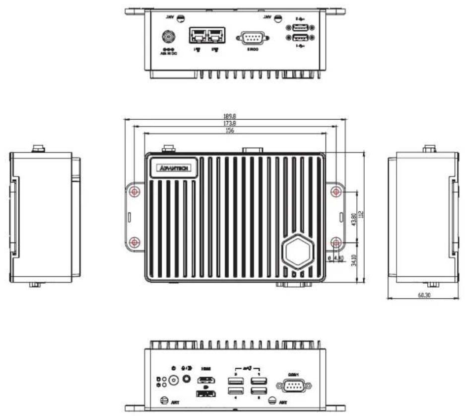
Figure 1.1 EI-52 Mechanical Dimensions
1.4.2 Weight
0.94 Kg
1.5 Power Requirements
1.5.1 System Power
■ Power Input: DC In 19V
1.5.2 RTC Battery
Lithium: 3 V/210 mAH
1.6 Environmental Specifications
1.6.1 Operating Temperature
-10 \~ 50 °C, with 0.7m/s air flow
1.6.2 Relative Humidity
■ 95% @ 40 °C (104 °F) (non-condensing)
1.6.3 Storage Temperature
-40 \~ 85 °C (-40 \~ 185 °F)
1.6.4 Vibration Tolerance
When the system is equipped with an SSD/mSATA: 3 Grms, IEC 60068-2-64, random, 5 \~ 500 Hz, 1 hr/axis, (x, y, z) 3 axes
1.6.5 Shock Tolerance
■ When the system is equipped with an SSD/mSATA: 30 G, IEC 60068-2-27, half sine, 11 ms duration
1.6.6 Safety Certification
UL, CB, CCC, BSMI
1.6.7 EMC Certification
CE, FCC, CCC, BSMI
Chapter 2
Hardware Installation
This chapter details instructions for installing EI-52 hardware and external I/O
2.1 Introduction
The following sections demonstrate the internal jumper settings and the external connector pin assignments.
2.2 Jumpers
2.2.1 Jumper Description
EI-52 can be configured to satisfy specific application requirements by setting jumpers. A jumper is a metal bridge used to close an electric circuit. It consists of two metal pins and a small metal clip (often protected by a plastic cover) that slides over the pins to connect them. To close a jumper, connect the pins with the clip. To open a jumper, remove the clip. Sometimes a jumper will have three pins, labeled 1, 2, and 3. For these jumpers, connect either pins 1 and 2, or 2 and 3.

The jumper settings are schematically diagramed in this manual as follows:

open

closed

closed 2-3
A pair of needle-nose pliers may be necessary when working with jumpers. Users with concerns regarding the ideal hardware configuration for your application should contact your local distributor or sales representative before making any changes. Usually, only a standard cable is required to make most connections.
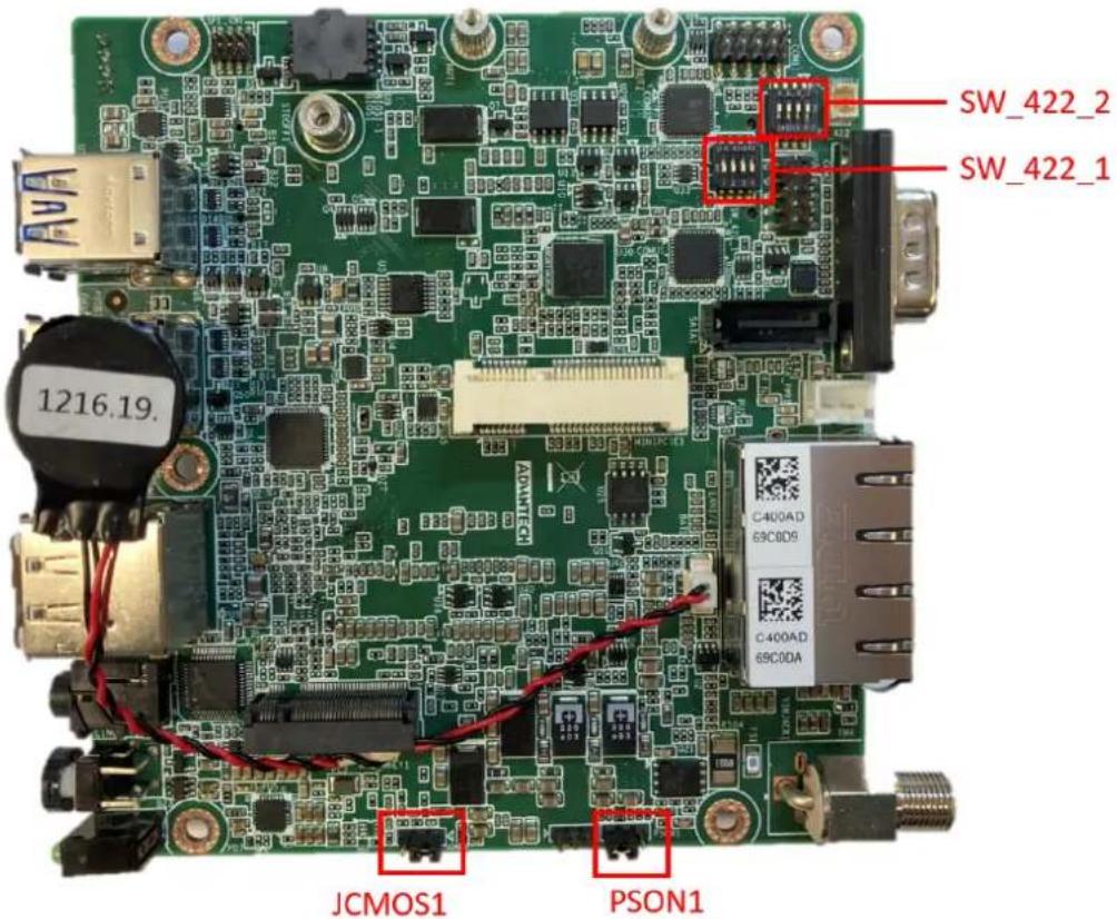
2.2.2 Jumper List
Table 2.1: Jumper Settings
| Location Function | |
| JCMOS1 Clear CMOS | |
| PSON1 Auto Power On Setting | |
| SW_422_1 | RS485/RS422 Fail Safe Enabled/Disabled |
| SW_422_2 | RS485/RS422 Fail Safe |
2.2.3 Jumper Location
2.2.4 Jumper Settings
Table 2.2: JCOMS1 Clear CMOS
Part Number 1653003101
| Description PIN HEADER 3x1P 2.0mm 180D(M) DIP 2000-13 WS |
| Default Setting (1-2) |
| Jumper Setting (2-3): Clear CMOS |
Table 2.3: PSON1 Auto Power On Setting
Part Number 1653003101
| Description PIN HEADER 3x1P 2.0mm 180D(M) DIP 2000-13 WS |
| Default Setting (2-3): ATX mode |
| Jumper Setting (1-2): AT mode |
SW_422_2 RS485 RS422 Fail Safe Off
Part Number 1600000402
| Description PIN HEADER 3x1P 2.0mm 180D(M) DIP 2000-13 WS |
| Jumper Setting (1-8) OFF: RS485 RS422 Fail Safe Off |
| Jumper Setting (2-7) OFF: RS485 RS422 Fail Safe Off |
| Jumper Setting (3-6) OFF: RS485 RS422 Fail Safe Off |
| Jumper Setting (4-5) OFF: RS485 RS422 Fail Safe Off |
SW_422_1 RS485 RS422 Fail Safe Enabled Disabled
Part Number 1600000402
Description DIP SW SMD 8P SPST P=1.27mm W=5.4mm KHS42E
Jumper Setting (1-8) OFF: RS485/RS422 Fail Safe Enabled Disabled
Jumper Setting (2-7) OFF: RS485/RS422 Fail Safe Enabled Disabled
Jumper Setting (3-6) OFF: RS485/RS422 Fail Safe Enabled Disabled
Jumper Setting (4-5) OFF: RS485/RS422 Fail Safe Enabled Disabled
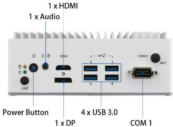
2.3 System I/O
Front View
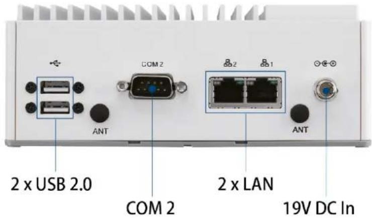
Rear View
2.4 External I/O
2.4.1 Power On/Off Button
EI-52 features a Power On/Off button with an LED indicators on the top side that show On status (Green LED)

Figure 2.1 Power On/Off Button
2.4.2 Power Input Connector
The power input connector supports DC in 19V.

2.4.3 Ethernet Connector (LAN)
EI-52 is equipped with one Intel® i219 and one Intel® i210 Ethernet controllers that are fully compliant with IEEE 802.3u 10/100/1000 Mbps CSMA/CD standards and connected to LAN1 and LAN2. The Ethernet port provides a standard RJ45 jack connector with LED indicators on the front side to show its Active/Link status (Green LED) and Speed status (Yellow LED).
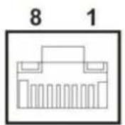
Figure 2.2 Ethernet Connector (LAN)
| Table 2.4: Ethernet Connector (LAN) Pin Definition |
| Pin 10/100/1000 Mbps Signal Name |
| 1 BI_DA+(GHz) |
| 2 BI_DA-(GHz) |
| 3 BI_DB+(GHz) |
| 4 BI_DC+(GHz) |
| 5 BI_DC-(GHz) |
| 6 BI_DB-(GHz) |
| 7 BI_DD+(GHz) |
| 8 BI_DD-(GHz) |
| H3 GND |
| H4 GND |
2.4.4 USB 3.0 Connector
EI-52 supports four USB 3.0 interfaces, which support Plug-and-Play functionality and hot swapping for up to 127 external devices. The USB interfaces comply with USB UHCI, Rev. 3.0.
USB 3.0 connectors contain legacy pins to interface to USB 2.0 devices and a new set of pins for USB 3.0 connectivity.
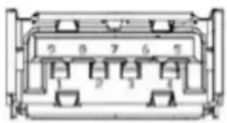
Figure 2.3 USB Connector
Table 2.5: USB Connector Pin Definition
| Pin Signal Name |
| 1 +5V |
| 2 D-_0 |
| 3 D+_0 |
| 4 GND |
| 5 USB0_SSRX- |
| 6 USB0_SSRX+ |
| 7 GND |
| 8 USB0_SSTX- |
| 9 USB0_SSTX+ |
2.4.5 Audio Connector
EI-52 features one phone jack connectors that support stereo Line Out and Mic In audio ports. The audio chip is controlled by ALC888S and compliant with the Azalea standard.

Figure 2.4 Audio Connector
Table 2.6: Audio Connector Pin Definition
| Pin Signal Name |
| 1 Mic In |
| 2 Line Out |
2.4.6 COM Connector
EI-52 provides two 9-pin D-sub connector, which supports RS232/422/485 serial communication interface ports. The default setting is RS-232, if you want to use RS-422/485, you can use the BIOS manual to change settings.

Figure 2.5 COM Connector
Table 2.7: COM Connector Pin Definition
| Pin RS-232 RS-422 RS-485 | ||
| 1 DCD Tx- DATA- | ||
| 2 RxD Tx+ DATA+ | ||
| 3 TxD Rx+ | NC | |
| 4 DTR | Rx- | NC |
| 5 GND | GND | GND |
| 6 DSR | NC NC | |
| 7 RTS | NC NC | |
| 8 CTS | NC NC | |
| 9 RI | NC NC | |
| NC represents “No Connection”. | ||
2.4.7 DP Connector
EI-52 offers one DP interface. The DP interface supports resolution up to 7680x4320.
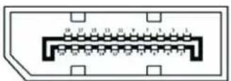
Table 2.8: DP Connector Pin Definition
| Pin | Signal Name | Pin | Signal Name |
| 1 | ML_Lane 0 (p) | 2 | GND |
| 2 | ML_Lane 0 (n) | 4 | ML_Lane 1 (p) |
| 5 | GND | 6 | ML_Lane 1 (n) |
| 7 | ML_Lane 2 (p) | 8 | GND |
| 9 | ML_Lane 2 (n) | 10 | ML_Lane 3 (p) |
| 11 | GND | 12 | ML_Lane 3 (n) |
| 13 | GND | 14 | GND |
| 15 | AUX CH (p) | 16 | GND |
| 17 | AUX CH (n) | 18 | Hot Plug |
| 19 | GND | 20 | DP_PWR |
Please notice that the DP cable in use should meet DP standard. If using DP cable which does not meet the standard, the cable may cause electricity leakage.
2.4.8 HDMI Connector
EI-52 offers two integrated 19-pin receptacle connector HDMI 2.0b interfaces. The HDMI link supports resolutions up to 4096 x 2304 @ 60 Hz.

Figure 2.6 HDMI Connector
Table 2.9: HDMI Connector Pin Definition
| Pin Signal Name |
| 1 HDMI_TX2+ |
| 2 GND |
| 3 HDMI_TX2- |
| 4 HDMI_TX1+ |
| 5 GND |
| 6 HDMI_TX1- |
| 7 HDMI_TX0+ |
| 8 GND |
| 9 HDMI_TX0- |
| 10 HDMI_CLK+ |
| 11 GND |
| 12 HDMI_CLK- |
| 13 NC |
| 14 NC |
| 15 HDMI_DCLK |
| 16 HDMI_DDAT |
| 17 GND |
| 18 +V5_HDMI-HPD |
| 19 DDP0_HPD |
| NC represents “No Connection”. |
2.4.9 Antenna Socket
EI-52 reserves four antenna sockets for installing wireless/LTE device antennas. Each antenna socket is labeled "ANT" for easy identification.

Figure 2.7 Antenna Socket
2.5 Installation
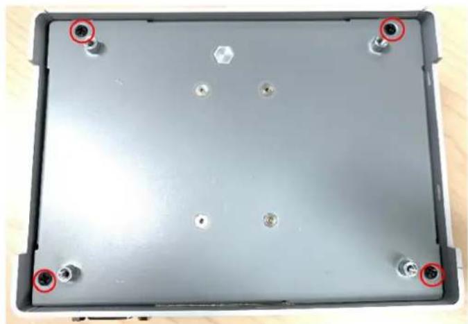
2.5.1 M.2 Installation
- Loosen the 4 screws affixing screws and remove the bottom cover.
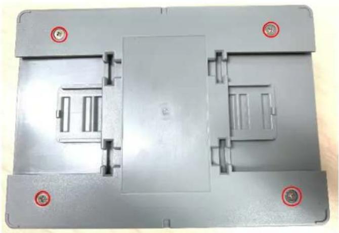
natural_image
Top-down view of a gray plastic enclosure with mounting holes and internal compartments (no text or symbols visible)- Loosen the 4 screws and remove the mechanical plate for storage.

natural_image
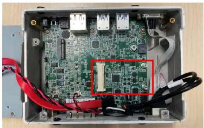
Top-down view of a gray electronic device casing with four mounting holes and metallic components (no text or symbols visible)- Install the M.2 2280 M key module.

natural_image
Interior view of an electronic device enclosure showing a green circuit board with red and black wires, no visible text or symbols.- Reinstall the mechanical plate for storage and bottom cover and secure it with screws (each 4x screws).

natural_image
Top-down view of a gray electronic device casing with four red circular markers on the front face (no text or symbols visible)
natural_image
Top-down view of a gray plastic enclosure with mounting holes and internal compartments (no text or symbols visible)2.5.2 Mini PCIe Installation
- Loosen the 4 screws affixing screws and remove the bottom cover.

natural_image
Top-down view of a gray plastic enclosure with mounting holes and internal compartments (no text or symbols visible)- Loosen the 4 screws and remove the mechanical plate for storage.
natural_image
Top-down view of a gray electronic device casing with four mounting points and a central hexagonal component (no text or symbols visible)- Install full-size mini PCIe module.
natural_image
Interior view of an electronic device enclosure showing a green circuit board with exposed components and red cables (no text or symbols visible)2.5.3 EI-52 Wall Mount
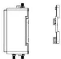
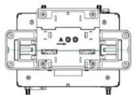
EI-52 default supports wall mount with the two wings on the bottom cover.

natural_image
Line drawing of a heat exchanger or server unit with cooling fins and ports (no text or symbols)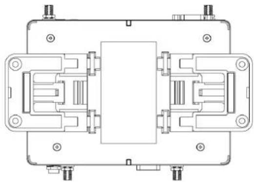
natural_image
Technical line drawing of a mechanical or electronic component assembly (no text or symbols visible)2.5.4 EI-52 DIN-Rail and VESA Mount (Optional AMK-A0040)
EI-52 default supports optional DIN-Rail and VESA mount with optional AMK-A0040 mounting kit.
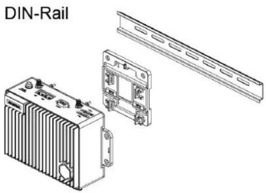

Assemble DIN-Rail/VESA Mounting bracket with EI-52:
Step 1
natural_image
Technical line drawing of a rectangular electronic component with mounting holes and side profile views (no text or symbols)Step 2
natural_image
Technical line drawing of an electrical component with mounting holes and internal circuitry (no text or symbols)Chapter 3
BIOS Settings
This chapter details the BIOS configuration instructions
3.1 Introduction
The AMI BIOS ROM has a built-in setup program - the BIOS Setup Utility - that allows users to modify the basic system configuration. All configuration data is stored in battery-backed CMOS to ensure the setup information is retained when the power is turned off.
This chapter describes the basic navigation of the EI-52 BIOS setup screens
![Aptio Setup - AMI Main Advanced Chipset Security Boot Save & Exit BIOS Vendor American Megatrends Core Version 5.0.1.9 0.02 x64 Compliancy UEFI 2.7.0; PI 1.6 Project Version EI EI52000U060X013 Build Date and Time 04/14/2021 11:00:50 Access Level Administrator Power Type [ATX Mode] Memory Information Total Memory 32768 MB Memory Frequency 2400 MT/s System Date [Wed 04/14/2021] System Time [11:25:34] Set the Date. Use Tab to switch between Date elements. Default Ranges: Year: 1998-9999 Months: 1-12 Days: Dependent on month Range of Years may vary. +: Select Screen 1↓: Select Item Enter: Select +/-: Change Opt. F1: General Help F2: Previous Values F3: Optimized Defaults F4: Save & Exit ESC: Exit Version 2.21.1278 Copyright (C) 2021 AMI](/content/2026/06/1228873/images/b3f27c2e11311a15735596ba1665733e6ea39f3a0e5caee2309f51b064f5ff0a.jpg)
3.2 Entering BIOS Setup
Turn on the computer and then press to enter the BIOS Setup menu.
3.2.1 Main Setup
Upon accessing the BIOS Setup Utility, users are presented with the Main setup page. Users can always return to the Main setup page by selecting the Main tab. The Main BIOS Setup page is shown below.
![Aptio Setup - AMI Main Advanced Chipset Security Boot Save & Exit BIOS Vendor American Megatrends Core Version 5.0.1.9 0.02 x64 Compliancy UEFI 2.7.0; PI 1.6 Project Version EI EIS2000U060X013 Build Date and Time 04/14/2021 11:00:50 Access Level Administrator Power Type [RTX Mode] Memory Information Total Memory 32768 MB Memory Frequency 2400 MT/s System Date [Wed 04/14/2021] System Time [11:25:34] Set the Date, Use Tab to switch between Date elements. Default Ranges: Year: 1998-9999 Months: 1-12 Days: Dependent on month Range of Years may vary. +:- Select Screen ↑↓: Select Item Enter: Select +/-: Change Opt. F1: General Help F2: Previous Values F3: Optimized Defaults F4: Save & Exit ESC: Exit Version 2.21.1278 Copyright (C) 2021 AMI](/content/2026/06/1228873/images/790355ba23b4bd381a089a7774e61027fd9750ad5248ec817f5280513582b9ce.jpg)
The Main BIOS setup page has two main frames. The left frame displays all the items accessible on the Main page. Items that are grayed out cannot be configured, whereas items presented in blue text can be configured. The right frame displays the key legend.
Located above the key legend is an area reserved for a text message. When an item is selected in the left frame, the item is presented in white text and often accompanied by a text message.
System Time/System Date
Use this option to change the system time and date. Highlight System Time or System Date using the
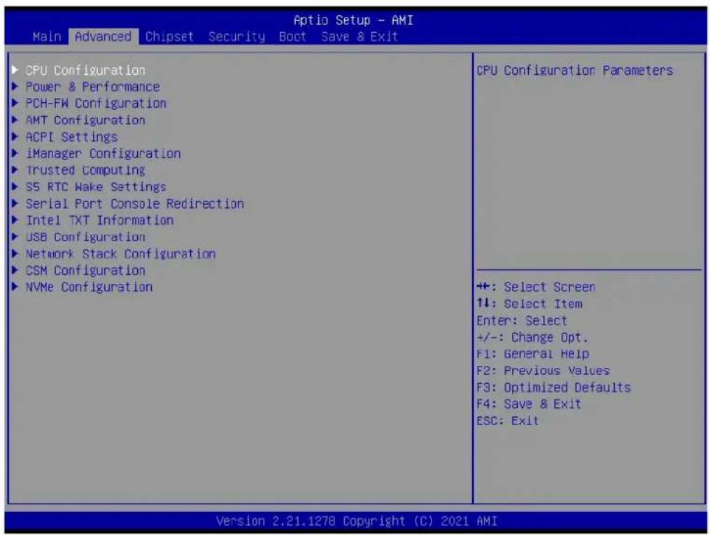
3.2.2 Advanced BIOS Setup
Select the Advanced tab from the BIOS Setup Utility to enter the Advanced BIOS Setup page. Select any of the items in the left frame of the screen, such as CPU Configuration, to access the sub menu for that item. The options for any of the Advanced BIOS Setup items can be displayed by highlighting the item using the
3.2.2.1 CPU Configuration
![Advanced CPU Configuration Type 11th Gen Intel(R) Core(TM) i5-1145G7E @ 2.60GHz ID 0x806C1 Speed 1500 MHz L1 Data Cache 48 KB x 4 L1 Instruction Cache 32 KB x 4 L2 Cache 1280 KB x 4 L3 Cache 8 MB L4 Cache N/A VMX Supported SMX/TXT Supported Intel (VMX) Virtualization [Enabled] Technology Active Processor Cores [All] Hyper-Threading [Enabled] MachineCheck [Enabled] MonitorMWait [Enabled] Intel Trusted Execution Technology [Disabled] Alias Check Request [Disabled] DPR Memory Size (MB) 4 Reset AUX Content [no] When enabled, a VMM can utilize the additional hardware capabilities provided by Vanderpool Technology. +: Select Screen ↑↓: Select Item Enter: Select +/-: Change Opt. F1: General Help F2: Previous Values F3: Optimized Defaults F4: Save & Exit ESC: Exit Version 2.21.1278 Copyright (C) 2021 AMI](/content/2026/06/1228873/images/1329b3e6f6b1d76469a3aeffa1ac8fe7b00986ae03f84624af85910333e0c7b0.jpg)
Intel (VMX) Virtualization Technology
When enabled, a VMM can utilize the additional hardware capabilities provided by Vanderpool Technology.
■ Active Processor Cores
Number of cores to enable in each processor package.
Hyper-Threading
Enable or Disable Hyper-Threading Technology.
MachineCheck
Enable/Disable Machine Check.
MonitorMWait
Enable/Disable MonitorMWait.
Intel Trusted Execution Technology
Enables utilization of additional hardware capabilities provided by Intel (R) Trusted Execution Technology. Changes require a full power cycle to take effect.
Alias Check Request
Enables Txt Alias Checking capability. Changes require full Txt capability before it will take effect. It is a one time only change, next reboot will be reset.
■ DPR Memory Size (MB)
Reserve DPR memory size (0-255) MB
Reset AUX Content
Reset TPM Aux content. Txt may not functional after AUX content gets reset.
3.2.2.2 Power & Performance

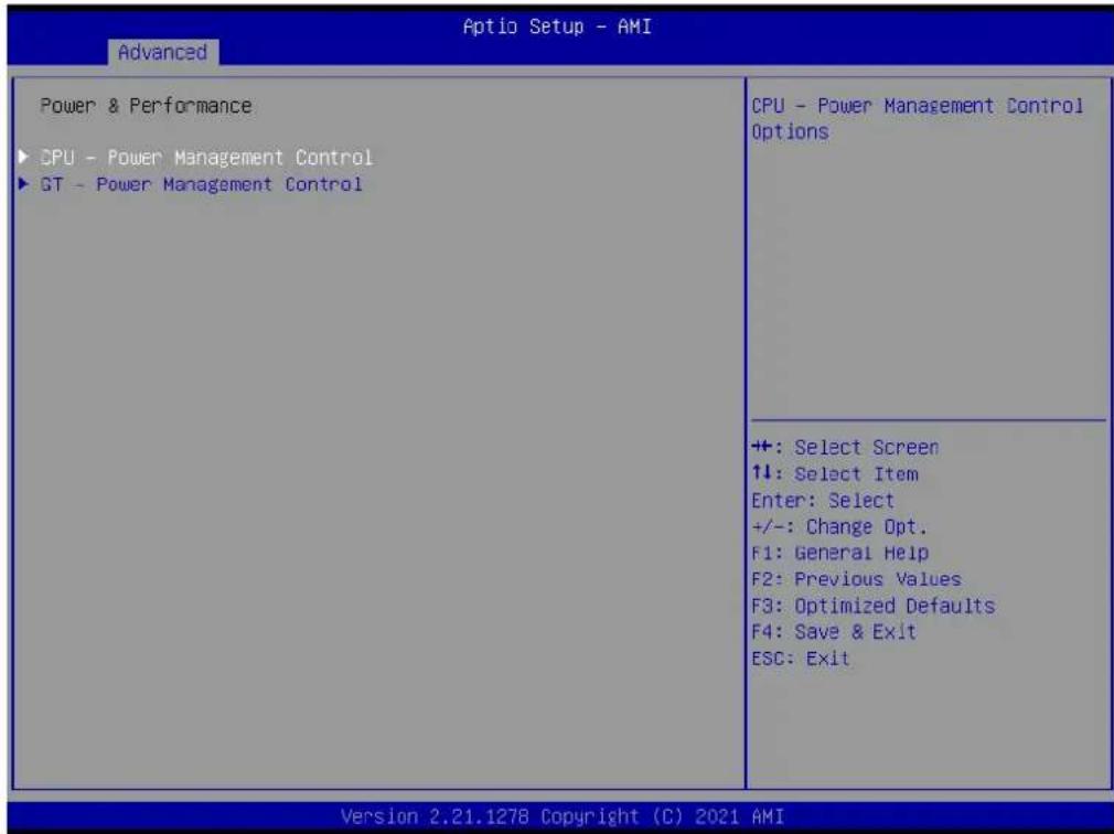
CPU - Power Management Control
■ Boot performance mode
Select the performance state that the BIOS will set starting from reset vector.
Intel(R) SpeedStep(tm)
Allows more than two frequency ranges to be supported.
Turbo Mode
Enable/Disable processor Turbo Mode (requires EMTTM enabled too). AUTO means enabled.
C state
Enable/Disable CPU Power Management. Allows CPU to go to C states when it's not 100% utilized.
GT - Power Management Control
RC6(Render Standby)
Check to enable render standby support.
■ Maximum GT frequency
Maximum GT frequency limited by the user.
■ Disable Turbo GT frequency
Enabled: Disables Turbo GT frequency. Disabled: GT frequency is not limited
3.2.2.3 PCH-FW Configuration

![Advanced Optio Setup - AMI ME Firmware Version 15.0.10.1414 ME Firmware Mode Normal Mode ME Firmware SKU Corporate SKU ME Firmware Status 1 0x90000255 ME Firmware Status 2 0x38858106 ME State [Enabled] Manageability Features State [Enabled] AMT BIOS Features [Enabled] ME Unconfig on RTC Clear [Enabled] ▶ Firmware Update Configuration When Disabled ME will not be unconfigured on RTC Clear ++: Select Screen 1↓: Select Item Enter: Select +/-: Change Opt. F1: General Help F2: Previous Values F3: Optimized Defaults F4: Save & Exit ESC: Exit Version 2.21.1278 Copyright (C) 2021 AMI](/content/2026/06/1228873/images/22f6a51b49fc694f6bd30faba8a94f4a10154a6dde80545c657a598448c5aa96.jpg)
![Optio Setup - AMI Advanced ME Firmware Version 15.0.10.1414 ME Firmware Mode Normal Mode ME Firmware SKU Corporate SKU ME Firmware Status 1 0x90000255 ME Firmware Status 2 0x3B858106 ME State [Enabled] Manageability Features State [Enabled] AMT BIOS Features [Enabled] ME Unconfig on RTC Clear [Enabled] ► Firmware Update Configuration Configure Management Engine Technology Parameters ++: Select Screen ↑↓: Select Item Enter: Select +/-: Change Opt. F1: General Help F2: Previous Values F3: Optimized Defaults F4: Save & Exit ESC: Exit Version 2.21.1278 Copyright (C) 2021 AMI](/content/2026/06/1228873/images/c6b8365d9382fd1e52c7016f9ed16565467897790b40d58be058aad5964eb53f.jpg)
![Aptio Setup - AMI Advanced Me FW Image Re-Flash [Disabled] FW Update [Enabled] Enable/Disable Me FW Image Re-Flash function. +: Select Screen ↑↓: Select Item Enter: Select +/-: Change Opt. F1: General Help F2: Previous Values F3: Optimized Defaults F4: Save & Exit ESC: Exit Version 2.21.1278 Copyright (C) 2021 AMI](/content/2026/06/1228873/images/fd6d7981247ae31200286941c4dcbe18269ecce983e56459843c509d868a1838.jpg)
ME State
When Disabled ME will be put into ME Temporarily Disabled Mode.
■ Manageability Features State
Enable/Disable Intel(R) Manageability features.
■ AMT BIOS Features
When disabled AMT BIOS Features are no longer supported and user is no longer able to access MEBx Setup.
■ ME Unconfig on RTC Clear
When Disabled ME will not be unconfigured on RTC Clear
Firmware Update Configuration
■ Me FW Image Re-Flash
Enable/Disable Me FW Image Re-Flash function.
FW Update
Enable/Disable ME FW Update function.
OEM Flags Settings
■ MEBx hotkey Pressed
Enable automatic MEBx hotkey press.
■ MEBx Selection Screen
Enable MEBx selection screen with 2 options: Press 1 to enter ME Configuration Screens. Press 2 to initiate a remote connection.
■ Hide Unconfigure ME Confirmation Prompt
Hide Unconfigure ME confirmation prompt when attempting ME unconfiguration.
■ MEBx OEM Debug Menu Enable
Enable OEM debug menu in MEBx.
Unconfigure ME
Unconfigure ME with resetting MEBx password to default.
3.2.2.4 ACPI Settings

![Advanced Aptio Setup - AMI ACPI Settings Enable ACPI Auto Configuration [Disabled] Enable Hibernation [Enabled] ACPI Sleep State [S3 (Suspend to RAM)] S3 Video Repost [Disabled] Enables or Disables BIOS ACPI Auto Configuration. ++: Select Screen ↑↓: Select Item Enter: Select +/-: Change Opt. F1: General Help F2: Previous Values F3: Optimized Defaults F4: Save & Exit ESC: Exit Version 2.21.1278 Copyright (C) 2021 AMI](/content/2026/06/1228873/images/3ef906180abecc7be502d7d50805d3316e09247cbee840edd37144e3dc3dd8a1.jpg)
■ Enable ACPI Auto Configuration
Enables or Disables BIOS ACPI Auto Configuration.
■ Enable Hibernation
nables or Disables System ability to Hibernate (OS/S4 Sleep State). This option may not be effective with some operating systems.
ACPI Sleep State
Select the highest ACPI sleep state the system will enter when the SUSPEND button is pressed.
S3 Video Repost
Enable or Disable S3 Video Repost.
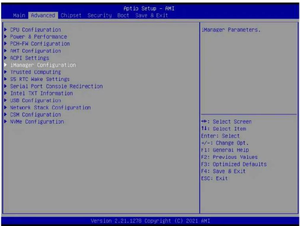
3.2.2.5 iManager Configuration
![Aptio Setup - AMI Advanced iManager Configuration iManager Chipset EIO-211 Firmware Version A01067788 Power Saving Mode [Normal] ► Serial Port 1 Configuration ► Serial Port 2 Configuration ► Hardware Monitor ► Watch Dog Timer Configuration Select Power Saving Mode ++: Select Screen ↑↓: Select Item Enter: Select +/-: Change Opt. F1: General Help F2: Previous Values F3: Optimized Defaults F4: Save & Exit ESC: Exit Version 2.21.1278 Copyright (C) 2021 AMI](/content/2026/06/1228873/images/4d0d317d62db48d10880002062f8c94c6d6f91c91a20947c61eb382d763cc4ef.jpg)
Power Saving Mode
Select Power Saving Mode.
Serial Port 1 Configuration
Serial Port
Eanble or Disable serial port.
Change Settings
Select an optimal settings for Super IO device.
COM1 Mode
COM1 mode select.
Serial Port 2 Configuration
Serial Port
Enable or Disable serial port.
Change Settings
Select an optimal settings for Super IO device.
COM2 Mode
COM2 mode select.
Hardware Monitor
Provide hardware monitor information
Watch Dog Timer Configuration
■ Watch Dog Timer
Enabled or Disabled
Watch Dog Timer function (Start before boot to OS and must stop by self)
3.2.2.6 Trusted Computing

![Advanced TPM 2.0 Device Found Firmware Version: 7.63 Vendor: IFX Security Device Support [Enable] Active PCR banks SHA256 Available PCR banks SHA-1,SHA256 SHA-1 PCR Bank [Disabled] SHA256 PCR Bank [Enabled] Pending operation [None] TPM 2.0 InterfaceType [TIS] Enables or Disables BIOS support for security device. 0.S. will not show Security Device. TCG EFI protocol and INT1A interface will not be available. +: Select Screen ↑↓: Select Item Enter: Select +/-: Change Opt. F1: General Help F2: Previous Values F3: Optimized Defaults F4: Save & Exit ESC: Exit Version 2.21.1278 Copyright (C) 2021 AMI](/content/2026/06/1228873/images/e3bf40ad46c199bdddfe091ddaf6d7643fc9d59664d8105ea025766edfdc13af.jpg)
■ Security Device Support
Enables or Disables BIOS support for security device.
SHA-1 PCR Bank
Enable or Disable SHA-1 PCR Bank.
SHA256 PCR Bank
Enable or Disable SHA256 PCR Bank.
Pending operation
Schedule an Operation for the security device.
3.2.2.7 S5 RTC Wake Settings
■ Wake System from S5
Enable or disable System wake on alarm event. When enabled, System will wake on the hr::min::sec specified
| Aptio Setup - AMI Main Advanced Chipset Security Boot Save & Exit | |
| CPU Configuration Power & Performance PCH-FW Configuration AMT Configuration ACPI Settings iManager Configuration Trusted Computing 35 RTC Wake Settings Serial Port Console Redirection Intel TXT Information USB Configuration Network Stack Configuration CSM Configuration NVMe Configuration | Enable system to wake from S5 using RTC alarm |
| +: Select Screen 1↓: Select Item Enter: Select +/-: Change Opt. F1: General Help F2: Previous Values F3: Optimized Defaults F4: Save & Exit ESC: Exit | |
| Version 2.21.1278 Copyright (C) 2021 AMI | |
| Advanced Aptio Setup - AMI | |
| Wake system from S5 [Disabled] | Enable or disable System wake on alarm event. Select FixedTime, system will wake on the hr::min::sec specified. Select DynamicTime, System u11 wake on the current time + Increase minute(s) |
| +: Select Screen ↑↓: Select Item Enter: Select +/-: Change Opt. F1: General Help F2: Previous Values F3: Optimized Defaults F4: Save & Exit ESC: Exit | |
| Version 2.21.1278 Copyright (C) 2021 AMI | |
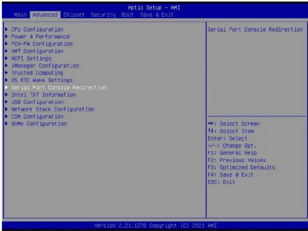
3.2.2.8 Serial Port Console Redirection
■ Console Redirection
Console Redirection Enable or Disable.
![Aptio Setup - AMI Advanced COMI Console Redirection [Disabled] ► Console Redirection Settings Console Redirection Enable or Disable. +: Select Screen ↑↓: Select Item Enter: Select +/-: Change Opt. F1: General Help F2: Previous Values F3: Optimized Defaults F4: Save & Exit ESC: Exit Version 2.21.1278 Copyright (C) 2021 AMI](/content/2026/06/1228873/images/a034d86c69e06f6b9b9b7279edc062142dfd7d87055e126600ea8b0fbcb6420b.jpg)
3.2.2.9 Intel TXT Information

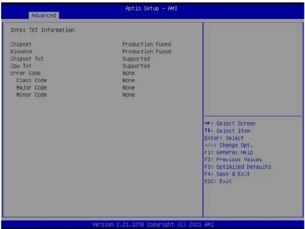
Provide Intel TXT information.
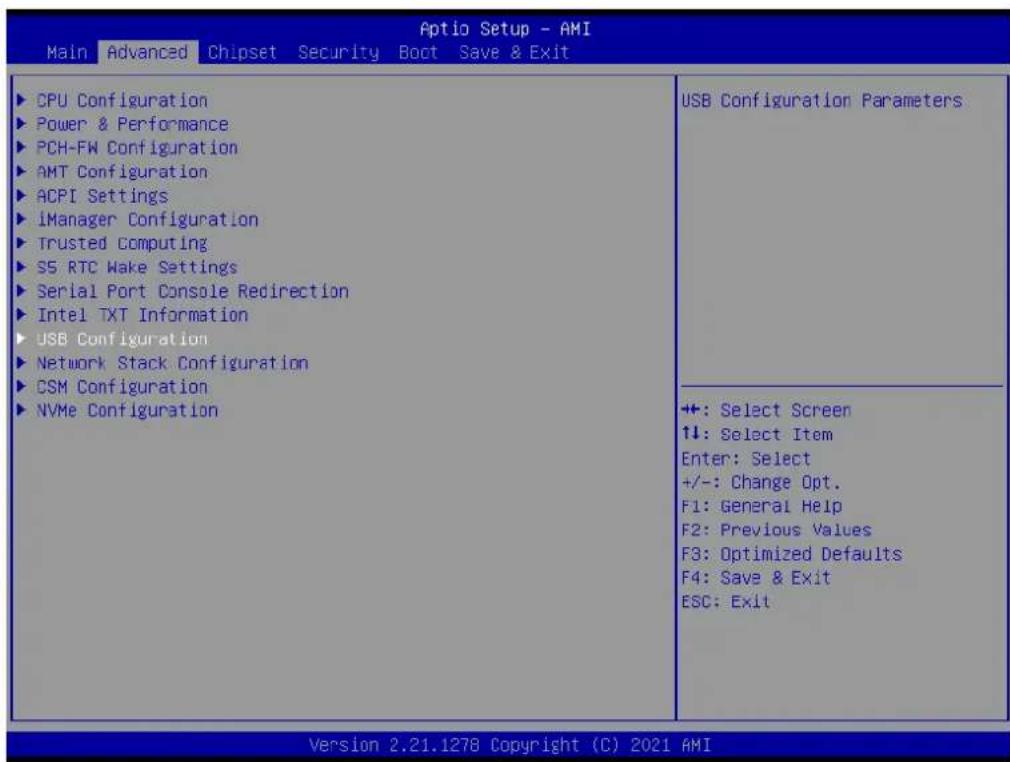
3.2.2.10 USB Configuration
![Advanced Optio Setup - AMI USB Configuration USB Module Version 26 USB Controllers: 1 XHCI USB Devices: 1 Drive, 1 Keyboard, 1 Mouse, 1 Hub Legacy USB Support [Enabled] XHCI Hand-off [Enabled] USB Mass Storage Driver Support [Enabled] USB hardware delays and time-outs: USB transfer time-out [20 sec] Device reset time-out [20 sec] Device power-up delay [Auto] Mass Storage Devices: JetFlashTS4GJFV30 8.07 [Auto] Enables Legacy USB support. AUTO option disables legacy support if no USB devices are connected. DISABLE option will keep USB devices available only for EFI applications. +: Select Screen ↑↓: Select Item Enter: Select +/-: Change Opt. F1: General Help F2: Previous Values F3: Optimized Defaults F4: Save & Exit ESC: Exit Version 2.21.1278 Copyright (C) 2021 AMI](/content/2026/06/1228873/images/88c3ea44fcabf34b65454e37c2f60321a58cedfaa40d5db38a3862feca22e85e.jpg)
Legacy USB Support
Enables Legacy USB support.
XHCI Hand-Off
This is a workaround for OSes without XHCI hand-off support.
USB Mass Storage Driver Support: Enable/Disable USB Mass Storage Driver Support.
USB transfer time-out
The time-out value for Control, Bulk, and Interrupt transfers.
■ Device Reset Timeout
USB mass storage device Start Unit command time-out.
■ Device Power-Up Delay
Maximum time the device will take before it properly reports itself to the Host Controller.
3.2.2.11 Network Stack Configuration
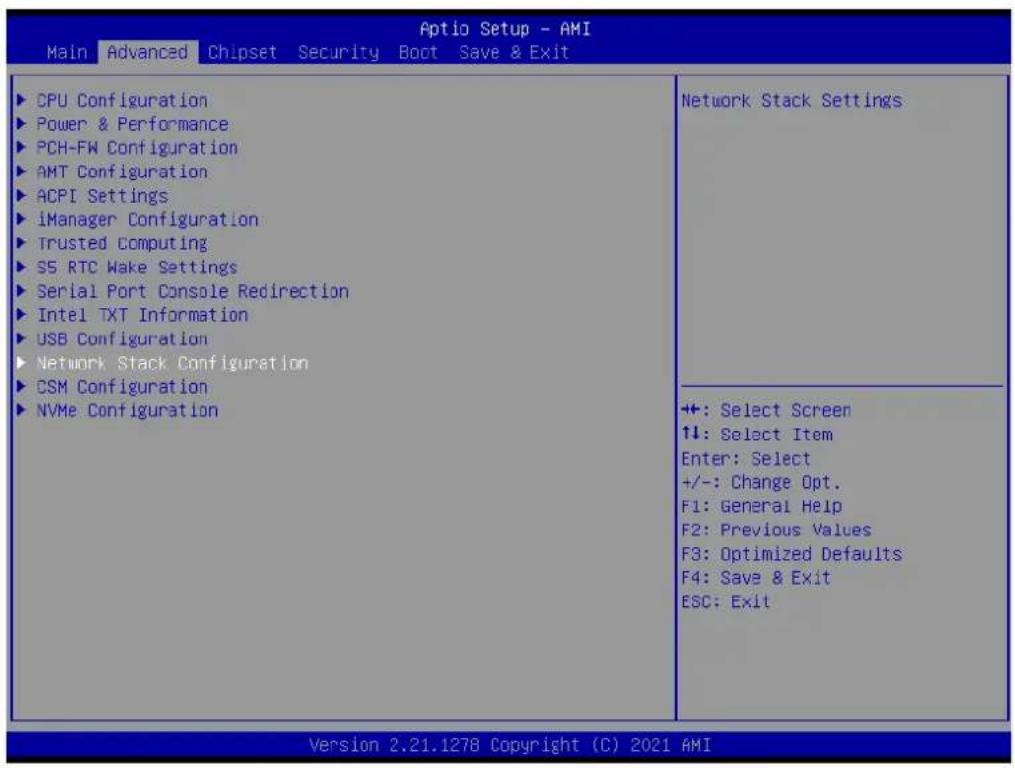
![Advanced Aptio Setup - AMI Network Stack [Disabled] Enable/Disable UEFI Network Stack +: Select Screen ↑↓: Select Item Enter: Select +/-: Change Opt. F1: General Help F2: Previous Values F3: Optimized Defaults F4: Save & Exit ESC: Exit Version 2.21.1278 Copyright (C) 2021 AMI](/content/2026/06/1228873/images/513c538a59c2353a3dd12a3dba16be86be2566e26cb79982561d9024e447534a.jpg)
Network Stack
Enable/Disable UEFI network stack.
3.2.2.12 CSM Configuration

![Aptio Setup - AMI Advanced Compatibility Support Module Configuration CSM Support [Disabled] Enable/Disable CSM Support. +: Select Screen ↑↓: Select Item Enter: Select +/-: Change Opt. F1: General Help F2: Previous Values F3: Optimized Defaults F4: Save & Exit ESC: Exit Version 2.21.1278 Copyright (C) 2021 AMI](/content/2026/06/1228873/images/5f4db32cc8a7c1fa453a9fb60971b730231099cafe88c3362d45f8a3e368aa58.jpg)
CSM Support
Enable/Disable CSM support.
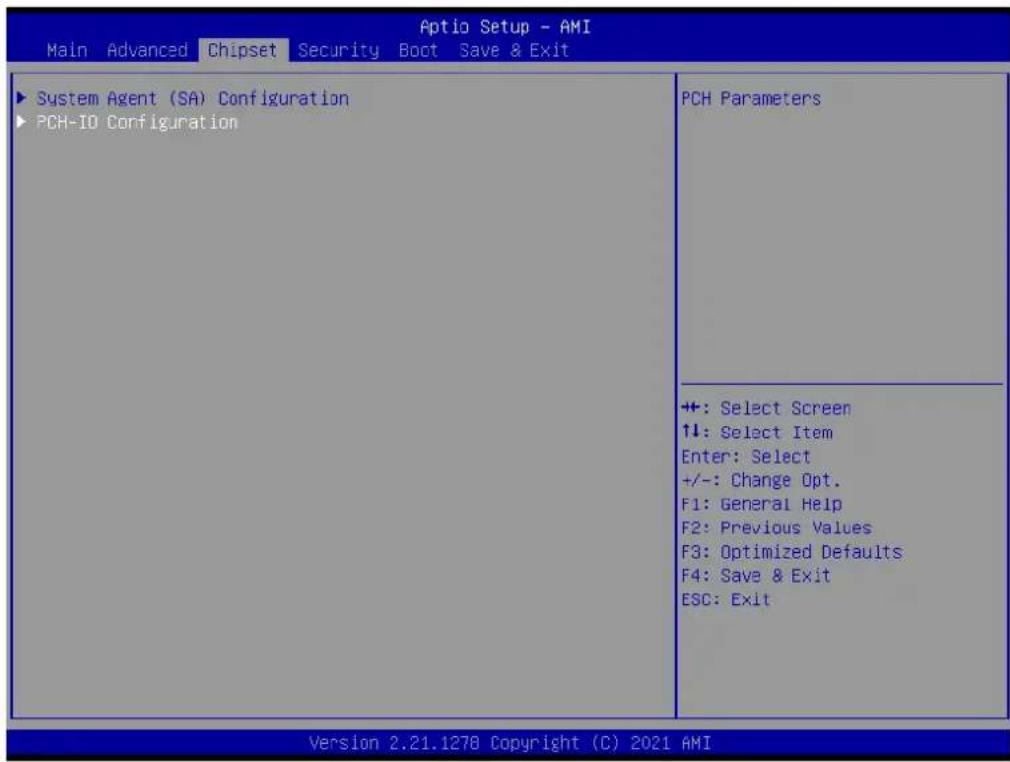
3.2.3 Chipset Configuration
3.2.3.1 System Agent (SA) Configuration
Memory Configuration
Display memory information.
VT-d
VT-d capability.
■ Above 4GB MMIO BIOS assignment
Enable/Disable above 4GB MemoryMappedIO BIOS assignment. This is enabled automatically when Aperture Size is set to 2048MB.

![Chipset Aptio Setup - AMI System Agent (SA) Configuration VT-d Supported ► Memory Configuration VT-d [Enabled] Above 4GB MMIO BIOS assignment [Enabled] Memory Configuration Parameters +: Select Screen ↑↓: Select Item Enter: Select +/-: Change Opt. F1: General Help F2: Previous Values F3: Optimized Defaults F4: Save & Exit ESC: Exit Version 2.21.1278 Copyright (C) 2021 AMI](/content/2026/06/1228873/images/5e3cf1d40ae2a562b984ff881d4d0ea829797748eee1918263e7f2f2b43013af.jpg)
3.2.3.2 PCH-IO Configuration
| Aptio Setup - AMI Chipset | |
| PCH-IO ConfigurationPCI Express ConfigurationSATA And RST ConfigurationUSB ConfigurationSecurity ConfigurationHD Audio Configuration | PCI Express Configuration settings |
| PCH LAN Controller [Enabled]LAN1 PXE OpROM [Disabled]Wake on LAN Enable [Enabled] | |
| Onboard LAN2 Controller [Enabled]LAN2 PXE OpROM [Disabled] | |
| PCIE Wake [Disabled]Restore AC Power Loss [Power Off] | +: Select Screen↑↓: Select ItemEnter: Select+/-: Change Opt.F1: General HelpF2: Previous ValuesF3: Optimized DefaultsF4: Save & ExitESC: Exit |
![Aptio Setup - AMI Chipset PCI Express Configuration M.2 E Key [Enabled] Select to Enable or Disable M.2 E Key. ++: Select Screen ↑↓: Select Item Enter: Select +/-: Change Opt. F1: General Help F2: Previous Values F3: Optimized Defaults F4: Save & Exit ESC: Exit Version 2.21.1278 Copyright (C) 2021 AMI](/content/2026/06/1228873/images/f43f4384bc9bbbe828de031ee544a9479d46bc5eb616f3212a4a78de1ff5a6a9.jpg)
PCI Express Configuration
M.2 E Key
Select to enable or disable M.2 E Key.
![Aptio Setup - AMI Chipset PCH-IO Configuration ► PCI Express Configuration ► SATA And RST Configuration ► USB Configuration ► Security Configuration ► HD Audio Configuration PCH LAN Controller [Enabled] LAN1 PXE OpROM [Disabled] Make on LAN Enable [Enabled] Onboard LAN2 Controller [Enabled] LAN2 PXE OpROM [Disabled] PCIE Wake [Disabled] Restore AC Power Loss [Power Off] SATA Device Options Settings +: Select Screen ↑↓: Select Item Enter: Select +/-: Change Opt. F1: General Help F2: Previous Values F3: Optimized Defaults F4: Save & Exit ESC: Exit Version 2.21.1278 Copyright (C) 2021 AMI](/content/2026/06/1228873/images/113e34c701614236c875c7faa47a9e3ec3878b6245aa4e5ba6fc59b80547d6ec.jpg)
![Aptio Setup - AMI Chipset SATA And RST Configuration SATA Controller(s) [Enabled] SATA Controller Speed Limit [Default] ► Software Feature Mask Configuration Aggressive LPM Support [Disabled] Serial ATA Port 1 Empty Port 1 [Enabled] SATA Device Type [Solid State Drive] Enable/Disable SATA Device. ++: Select Screen ↑↓: Select Item Enter: Select +/-: Change Opt. F1: General Help F2: Previous Values F3: Optimized Defaults F4: Save & Exit ESC: Exit Version 2.21.1278 Copyright (C) 2021 AMI](/content/2026/06/1228873/images/e267b5ce38c0ee8329899377d656b31d13fa6127c198c6a54e105a2be371d627.jpg)
SATA And RST Configuration
■ SATA Controller(s)
Enable/Disable SATA Device.
■ SATA Controller Speed Limit
Indicates the maximum speed the SATA controller can support.
■ HDD Unlock
If enabled, indicates that the HDD password unlock in the OS is enabled.
LED Locate
If enabled, indicates that the LED/SGPIO hardware is attached and ping to locate feature is enabled on the OS.
Aggressive LPM Support
Enable PCH to aggressively enter link power state.
Port 1
Enable or disable SATA port.
■ SATA Device Type
Identify the SATA port is connected to Solid State Drive or Hard Disk Drive
![Aptio Setup - AMI Chipset PCH-IO Configuration ► PCI Express Configuration ► SATA And RST Configuration ► USB Configuration ► Security Configuration ► HD Audio Configuration PCH LAN Controller [Enabled] LAN1 PXE OpROM [Disabled] Make on LAN Enable [Enabled] Onboard LAN2 Controller [Enabled] LAN2 PXE OpROM [Disabled] PCIE Wake [Disabled] Restore AC Power Loss [Power Off] USB Configuration settings ++: Select Screen ↑↓: Select Item Enter: Select +/-: Change Opt. F1: General Help F2: Previous Values F3: Optimized Defaults F4: Save & Exit ESC: Exit Version 2.21.1278 Copyright (C) 2021 AMI](/content/2026/06/1228873/images/d2117eca360b569ba2664bc6d82486a4e3266a88c2fe2324c8507ad8f7266bac.jpg)
![Chipset Aptio Setup - AMI USB Configuration xDCI Support [Disabled] USB2 PHY Sus Well Power Gating [Enabled] USB3 Link Speed Selection [GEN2] USB PDU Programming [Enabled] USB Overcurrent [Enabled] USB Overcurrent Lock [Enabled] USB Port Disable Override [Disabled] Enable/Disable xDCI (USB OTG Device). ++: Select Screen 1↓: Select Item Enter: Select +/-: Change Opt. F1: General Help F2: Previous Values F3: Optimized Defaults F4: Save & Exit ESC: Exit Version 2.21.1278 Copyright (C) 2021 AMI](/content/2026/06/1228873/images/c624dd282c71cedabfdcdb0c639214e7435c137fdb1a6fb35b30446366e85f5a.jpg)
USB Configuration
xDCI Support
Enable/Disable xDCI (USB OTG Device).
USB2 PHY Sus Well Power Gating
Select 'Enabled' to enable SUS Well PG for USB2 PHY.
USB3 Link Speed Selection
This option is to select USB3 Link Speed GEN1 or GEN2
USB PDO Programming
Select 'Enabled' if Port Disable Override functionality is used.
USB Overcurrent
Select 'Disabled' for pin-based debug.
USB Overcurrent Lock
Select 'Enabled' if Overcurrent functionality is used. Enabling this will make xHCI controller consume the Overcurrent mapping data.
USB Port Disable Override
Selectively Enable/Disable the corresponding USB port from reporting a Device Connection to the controller.
| Chipset Aptio Setup - AMI | |
| PCH-IO Configuration ► PCI Express Configuration ► SATA And RST Configuration ► USB Configuration ► Security Configuration ► HD Audio Configuration | Security Configuration settings |
| PCH LAN Controller [Enabled] LAN1 PXE OpROM [Disabled] Wake on LAN Enable [Enabled] | |
| Onboard LAN2 Controller [Enabled] LAN2 PXE OpROM [Disabled] | |
| PCIE Wake [Disabled] Restore AC Power Loss [Power Off] | +: Select Screen ↑↓: Select Item Enter: Select +/-: Change Opt. F1: General Help F2: Previous Values F3: Optimized Defaults F4: Save & Exit ESC: Exit |
![Chipset Aptio Setup - AMI Security Configuration RTC Memory Lock [Enabled] BIOS Lock [Enabled] Enable will lock bytes 38h-3Fh in the lower/upper 128-byte bank of RTC RAM ++: Select Screen ↑↓: Select Item Enter: Select +/-: Change Opt. F1: General Help F2: Previous Values F3: Optimized Defaults F4: Save & Exit ESC: Exit Version 2.21.1278 Copyright (C) 2021 AMI](/content/2026/06/1228873/images/4007a51ef19329c2653b7214fded51d4c6e2fa92b35753f785651c40d53070c0.jpg)
Security Configuration
■ RTC Memory Lock
Enable will lock bytes 38h-3Fh in the lower/upper 128-byte bank of RTC RAM.
BIOS Lock
Enable/Disable the PCH BIOS Lock Enable feature. Required to be enabled to ensure SMM protection of flash.
![Chipset Aptio Setup - AMI PCH-IO Configuration ► PCI Express Configuration ► SATA And RST Configuration ► USB Configuration ► Security Configuration ► HD Audio Configuration PCH LAN Controller [Enabled] LAN1 PXE OpROM [Disabled] Make on LAN Enable [Enabled] Onboard LAN2 Controller [Enabled] LAN2 PXE OpROM [Disabled] PCIE Wake [Disabled] Restore AC Power Loss [Power Off] HD Audio Subsystem Configuration Settings +: Select Screen 11: Select Item Enter: Select +/-: Change Opt. F1: General Help F2: Previous Values F3: Optimized Defaults F4: Save & Exit ESC: Exit Version 2.21.1278 Copyright (C) 2021 AMI](/content/2026/06/1228873/images/56c42c5b31b8d7c7eb4c305b9c0c7139e29ae3a19ea8bd631abeb44883c97672.jpg)
![Aptio Setup - AMI Chipset HD Audio Subsystem Configuration Settings HD Audio [Enabled] Control Detection of the HD-Audio device. Disabled = HDA will be unconditionally disabled Enabled = HDA will be unconditionally enabled. +: Select Screen ↑↓: Select Item Enter: Select +/-: Change Opt. F1: General Help F2: Previous Values F3: Optimized Defaults F4: Save & Exit ESC: Exit Version 2.21.1278 Copyright (C) 2021 AMI](/content/2026/06/1228873/images/c3012feaa516f3276f1f2d2931d83a9578308790f91ea3d8ff70d0dc72e5663f.jpg)
HD Audio Configuration
HD Audio
Control Detection of the HD-Audio device.
PCH LAN Controller
Enable/Disable onboard NIC.
LAN1 PXE OpROM
Enable or disable boot option for LAN1 Controller.
Wake on LAN Enable
Enable/Disable integrated LAN to wake the system.
Onboard LAN2 Controller
Select to Enable or Disable Onboard LAN2 Controller.
LAN2 PXE OpROM
Enable or disable boot option for LAN2 Controller.
PCIE Wake
Enable or disable PCIE to wake the system from S5.
Restore AC Power Loss
Specify what state to go to when power is re-applied after a power failure (G3 state)
3.2.4 Security

![Aptio Setup - AMI Security System Mode Secure Boot Secure Boot Mode ►Restore Factory Keys ►Reset To Setup Mode ►Key Management Setup [Enabled] Not Active [Standard] Secure Boot feature is Active if Secure Boot is Enabled, Platform Key(PK) is enrolled and the System is in User mode. The mode change requires platform reset +: Select Screen 1↓: Select Item Enter: Select +/-: Change Opt. F1: General Help F2: Previous Values F3: Optimized Defaults F4: Save & Exit ESC: Exit Version 2.21.1278 Copyright (C) 2021 AMI](/content/2026/06/1228873/images/9e1b9be9a827cb50f9cca3b0d1ece3a55a15f529490f8178c71482ca8bc180f5.jpg)
Security
Administrator Password
Set Administrator Password.
User Password
Set User Password.
Secure Boot
Secure Boot
Secure Boot feature is Active if Secure Boot is Enabled, Platform Key(PK) is enrolled and the System is in User mode. The mode change requires platform reset.
- Secure Boot Mode
Secure Boot mode options: Standard or Custom. In Custom mode, Secure Boot Policy variables can be configured by a physically present user without full authentication.
3.2.5 Boot
![Aptio Setup - AMI Main Advanced Chipset Security Boot Save & Exit Boot Configuration Setup Prompt Timeout 1 Bootup NumLock State [On] Quiet Boot [Disabled] Boot Option Priorities Boot Option #1 [UEFI: JetFlashTS4GJFV30 8.07, Partition 1 (JetFlashTS4GJFV30 8.07)] Number of seconds to wait for setup activation key. 65S55(0xFFFF) means indefinite waiting. +: Select Screen ↑↓: Select Item Enter: Select +/-: Change Opt. F1: General Help F2: Previous Values F3: Optimized Defaults F4: Save & Exit ESC: Exit Version 2.21.1278 Copyright (C) 2021 AMI](/content/2026/06/1228873/images/adeb6d03df8be60c96952c9585b2575b3b6506c93e919105e8b77a87f4b47358.jpg)
Boot
Setup Prompt Timeout
Number of seconds to wait for setup activation key.
■ Bootup NumLock State
Select the keyboard NumLock state.
Quiet Boot
Enables or disables Quiet Boot option.
3.2.6 Save & Exit
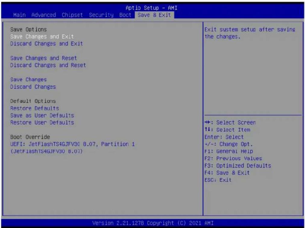
■ Changes and Exit
Exit system setup after saving the changes.
- Discard Changes and Exit
Exit system setup without saving any changes.
■ Save Changes and Reset
Reset the system after saving the changes.
- Discard Changes and Reset
Reset system setup without saving any changes.
■ Save Changes
Save Changes done so far to any of the setup options.
- Discard Changes
Discard Changes done so far to any of the setup options.
- Restore Defaults
Restore/Load Default values for all the setup options.
- Save as User Defaults
- Save the changes done so far as User Defaults.
- Restore User Defaults
Restore the User Defaults to all the setup options.
Appendix A
LAN Order Change Method
A.1 Problem Statement
If it is necessary for the LAN order recognized by OS matches the LAN order of printing on I/O plate to be exactly the same, please do not order EI-52 207 OS image. To make the LAN order be the same, users need to order Windows 10 license key, install Windows 10 via iso file and follow the instructions in below “Addressing the LAN order” section.
The phenomenon that LAN order recognized by OS does not match the LAN order of printing on I/O plate is because:
When installing Windows 10, the inbox driver will recognize I210 LAN chip and arrange it to the first order. Therefore, after users install the I219 LAN driver manually, the I219 will be recognized by OS as LAN 2, and LAN 1 is I210. However, this order does not match the LAN label printed on EI-52 I/O plate, which LAN 1 is I219, and LAN 2 is I210, as below figure shown.

Figure A.1 The physical connector label is LAN 1 for I219, and LAN 2 for I210.
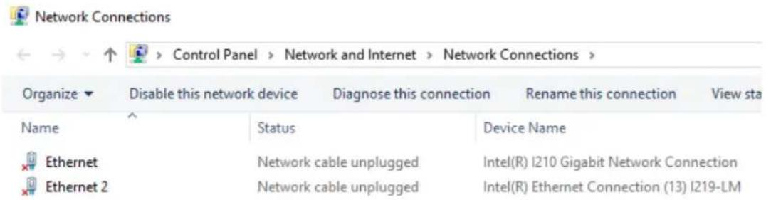
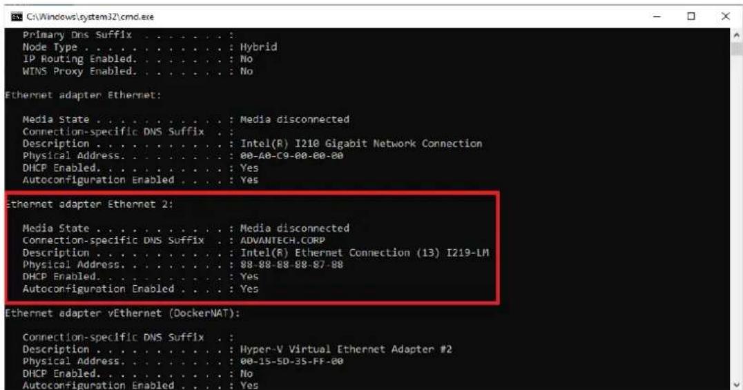
Figure A.2 After users install I219 LAN driver manually, I219 is set to Ethernet 2 (LAN 2), which does not match the order in Figure 1.
A.2 Addressing the LAN Order
To fix the LAN order mismatch phenomenon, users have to:
- Disable LAN2 in BIOS BEFORE installing Windows 10 via iso file, as Figure 3 shown.
- Install Windows 10 via iso file, and activate by the purchased license key.
- Install I219 LAN driver.
- Reboot, enter BIOS and enable LAN2 controller. Save and exit BIOS.
- Confirm in OS whether the LAN order recognized by OS matches that of the physical connector printing on I/O plate.
![Chipset PCH-IO Configuration ► PCI Express Configuration ► SATA And RST Configuration ► USB Configuration ► Security Configuration ► HD Audio Configuration PCH LAN Controller [Enabled] LAN1 PXE OpROM [Disabled] Wake on LAN Enable [Enabled] Onboard LAN2 Controller [Disabled]](/content/2026/06/1228873/images/cdbd6426a8f5d619c03a2179899754134a9484c6badb5b40013016987ebc5156.jpg)
Figure A.3 Disable the LAN 2 controller in BIOS (BIOS → Chipset → PCH-IO Configuration → Onboard LAN2 controller → [Disabled]).
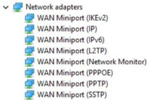
Figure A.4 Before installing I219 LAN driver, there is no any LAN adapter shown in device manager.
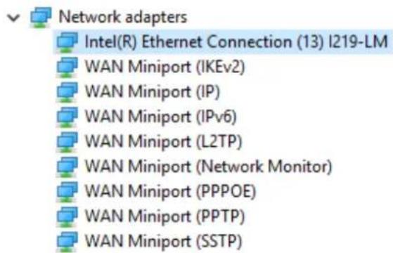
Figure A.5 After installing I219 LAN driver, I219 will be recognized and shown in device manager.
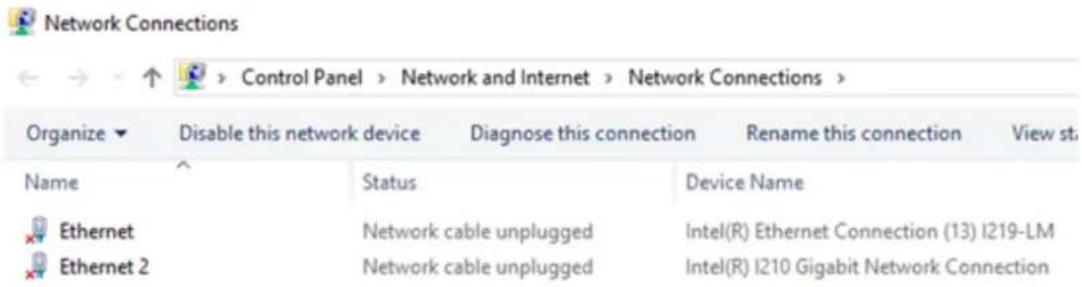
Figure A.6 Users should see that LAN 1 is I219, and LAN 2 is I210 in OS, which matches the printing on I/O plate as shown in Figure 1.
ADVANTECH
Enabling an Intelligent Planet
www.advantech.com
Please verify specifications before quoting. This guide is intended for reference purposes only.
All product specifications are subject to change without notice.
No part of this publication may be reproduced in any form or by any means, such as electronically, by photocopying, recording, or otherwise, without prior written permission from the publisher.
All brand and product names are trademarks or registered trademarks of their respective companies.
© Advantech Co., Ltd. 2021

- EI-52
- Fanless Edge Intelligence System
- Attention!
- Copyright
- Acknowledgments
- Product Warranty (2 Years)
- Declaration of Conformity
- FCC Class B
- Technical Support and Assistance
- Warnings, Cautions, and Notes
- Safety Instructions
- Ordering Information
- Optional Accessories
- Contents
- Chapter 1 General Introduction ......1
- Chapter 2 Hardware Installation ....7
- Chapter 3 BIOS Settings ...... 19
- Appendix A LAN Order Change Method...... 53
- Chapter 1
- Introduction
- Intel 11th Gen. High Performance Processors
- HDMI+DP Dual Display & Compact-size with Multiple I/Os
- Advantech WISE-DeviceOn, Edge X Data Acquisition API integrated
- Product Features
- General
- Display
- Ethernet
- Chipset
- Functional Specifications
- Processor
- Chipset
- Others
- Mechanical Specifications
- System Dimensions
- Weight
- Power Requirements
- System Power
- RTC Battery
- Environmental Specifications
- Operating Temperature
- Relative Humidity
- Storage Temperature
- Vibration Tolerance
- Shock Tolerance
- Safety Certification
- EMC Certification
- Chapter 2
- Hardware Installation
- Introduction
- Jumpers
- Jumper Description
- Jumper List
- Jumper Location
- Jumper Settings
- System I/O
- External I/O
- Power On/Off Button
- Power Input Connector
- Ethernet Connector (LAN)
- USB 3.0 Connector
- Audio Connector
- COM Connector
- DP Connector
- HDMI Connector
- Antenna Socket
- Installation
- M.2 Installation
- Mini PCIe Installation
- EI-52 Wall Mount
- EI-52 DIN-Rail and VESA Mount (Optional AMK-A0040)
- Chapter 3
- BIOS Settings
- Introduction
- Entering BIOS Setup
- Main Setup
- System Time/System Date
- Advanced BIOS Setup
- CPU Configuration
- Power & Performance
- CPU - Power Management Control
- GT - Power Management Control
- PCH-FW Configuration
- ■ AMT BIOS Features
- ■ ME Unconfig on RTC Clear
- Firmware Update Configuration
- ■ Me FW Image Re-Flash
- FW Update
- OEM Flags Settings
- ■ MEBx hotkey Pressed
- ■ MEBx Selection Screen
- ■ Hide Unconfigure ME Confirmation Prompt
- ■ MEBx OEM Debug Menu Enable
- Unconfigure ME
- ACPI Settings
- ACPI Sleep State
- S3 Video Repost
- iManager Configuration
- Serial Port 1 Configuration
- Serial Port 2 Configuration
- Hardware Monitor
- Watch Dog Timer Configuration
- Trusted Computing
- S5 RTC Wake Settings
- ■ Wake System from S5
- Serial Port Console Redirection
- ■ Console Redirection
- Intel TXT Information
- USB Configuration
- Network Stack Configuration
- Network Stack
- CSM Configuration
- CSM Support
- Chipset Configuration
- System Agent (SA) Configuration
- Memory Configuration
- PCH-IO Configuration
- PCI Express Configuration
- M.2 E Key
- SATA And RST Configuration
- USB Configuration
- USB3 Link Speed Selection
- USB PDO Programming
- USB Overcurrent
- USB Overcurrent Lock
- USB Port Disable Override
- Security Configuration
- ■ RTC Memory Lock
- BIOS Lock
- HD Audio Configuration
- HD Audio
- PCH LAN Controller
- LAN1 PXE OpROM
- Wake on LAN Enable
- Onboard LAN2 Controller
- LAN2 PXE OpROM
- PCIE Wake
- Restore AC Power Loss
- Security
- Security
- Secure Boot
- - Secure Boot Mode
- Boot
- Boot
- Save & Exit
- Appendix A
- A.1 Problem Statement
- A.2 Addressing the LAN Order
- ADVANTECH
- www.advantech.com
Brand : Advantech
Model : EI-52-S2A1
Category : Unknown