
ET91000LCOAM - Unspecified StarTech.com - Free user manual and instructions
Find the device manual for free ET91000LCOAM StarTech.com in PDF.

| Product Type | Gigabit Ethernet Fiber Media Converter |
| Part Number | ET91000LCOAM |
| Interfaces | 1x RJ45 (10/100/1000 Mbps), 1x LC (Multimode Fiber) |
| Fiber Type | Multimode (MM) |
| Wavelength | 850 nm |
| Maximum Distance (Fiber) | 550 m |
| Copper Speed | 10/100/1000 Mbps (Auto-Negotiation) |
| Housing Material | Metal |
| Management | Web-based (HTTP), IEEE 802.3ah OAM |
| OAM Support | Yes (802.3ah) |
| Jumbo Frame Support | Up to 9K bytes (configurable) |
| VLAN Support | Up to 16 groups, Q-in-Q, Management VLAN |
| Power Adapter | Universal (NA/UK/EU/AU), Input: 100-240V AC, Output: 5V DC 2A (estimated) |
| Dimensions (approx) | 80 x 55 x 25 mm (3.15 x 2.17 x 0.98 in) |
| Weight (approx) | 200 g (0.44 lbs) |
| Operating Temperature | 0°C to 50°C (32°F to 122°F) estimated |
| Compliance | FCC Class B |
| Warranty | 2 Years |
| Included Accessories | Power adapter, Instruction manual |
Frequently Asked Questions - ET91000LCOAM StarTech.com
User questions about ET91000LCOAM StarTech.com
0 question about this device. Answer the ones you know or ask your own.
Ask a new question about this device
Download the instructions for your Unspecified in PDF format for free! Find your manual ET91000LCOAM - StarTech.com and take your electronic device back in hand. On this page are published all the documents necessary for the use of your device. ET91000LCOAM by StarTech.com.
USER MANUAL ET91000LCOAM StarTech.com
In-Band OAM Gigabit Ethernet to MM LC Fiber Media Converter - 550m, Metal Housing
ET91000LCOAM

natural_image
Black StarTech Zicom network device with Ethernet port and ports (no visible text or symbols on body)*actual product may vary from photos
For the most up-to-date information, please visit: www.startech.com
FCC Compliance Statement
This equipment has been tested and found to comply with the limits for a Class B digital device, pursuant to part 15 of the FCC Rules. These limits are designed to provide reasonable protection against harmful interference in a residential installation. This equipment generates, uses and can radiate radio frequency energy and, if not installed and used in accordance with the instructions, may cause harmful interference to radio communications. However, there is no guarantee that interference will not occur in a particular installation. If this equipment does cause harmful interference to radio or television reception, which can be determined by turning the equipment off and on, the user is encouraged to try to correct the interference by one or more of the following measures:
• Reorient or relocate the receiving antenna.
- Increase the separation between the equipment and receiver.
- Connect the equipment into an outlet on a circuit different from that to which the receiver is connected.
- Consult the dealer or an experienced radio/TV technician for help.
Use of Trademarks, Registered Trademarks, and other Protected Names and Symbols
This manual may make reference to trademarks, registered trademarks, and other protected names and/or symbols of third-party companies not related in any way to StarTech.com. Where they occur these references are for illustrative purposes only and do not represent an endorsement of a product or service by StarTech.com, or an endorsement of the product(s) to which this manual applies by the third-party company in question. Regardless of any direct acknowledgement elsewhere in the body of this document, StarTech.com hereby acknowledges that all trademarks, registered trademarks, service marks, and other protected names and/or symbols contained in this manual and related documents are the property of their respective holders.
Table of Contents
Product Overview .... 1
Side 1 .... 1
Side 2....1
Introduction......2
Packaging Contents 2
System Requirements....2
Factory Reset Procedure 2
Installation ....3
Installation into ETCHS2U Chassis....4
Operation 4
System Information Section....5
Local Settings Section 6
Tools Section......15
Logging Out....17
Specifications....18
Technical Support 19
Warranty Information....19
Product Overview
Side 1
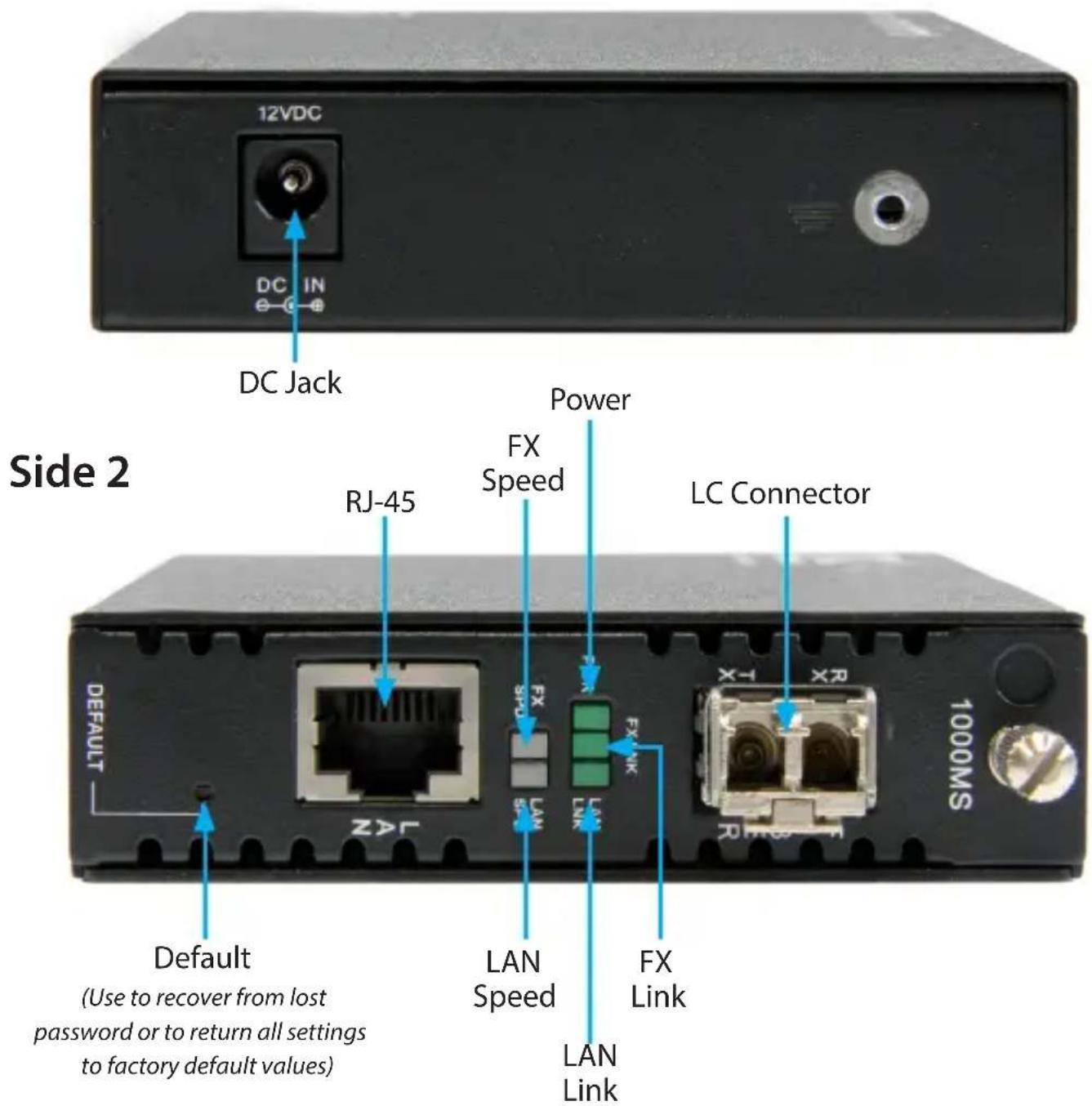
The LAN Speed and FX Speed LEDs use 2 colors to indicate speed. Green indicates Fast Ethernet (100Mbps), while Yellow indicates Gigabit Ethernet. When the LEDs are off, it indicates a speed of 10Mbps.
Introduction
Packaging Contents
• 1x Fiber Media Converter
• 1x Universal Power Adapter (NA/UK/EU/AU)
• 1x Instruction Manual
System Requirements
• 1000BASE-T compatible Ethernet network equipment
- RJ45 terminated UTP Cat5e or better Ethernet cable
• Available AC electrical outlet
Factory Reset Procedure
Apply power to the unit and allow approximately 30 seconds to fully boot. Using a pencil or a ball-point pen, press the "DEFAULT" push button located on the face plate and hold it for 6 seconds. The media converter will be restored to its factory default values, which are:
IP: 10.1.1.1
Subnet Mask: 255.255.255.0
Gateway: 10.1.1.254
Username/Password: "admin"
Installation
- Connect the fiber optic network cable from a computer/switch/media converter to the LC connector on the media converter.
NOTE: When connecting the fiber cable, make sure to connect the Tx (transmit) terminal on one end, with the Rx (receive) terminal on the other end. - Connect a UTP Ethernet cable, from a computer/switch to the RJ45 jack on the media converter.
- Connect the power adapter to the media converter.
The following example illustrates the connection scheme when connecting from a 1000BASE-T Ethernet port of a hub/switch to a 1000BASE-SX/LX port of another hub/ switch. Through the fiber media converter:

The following example illustrates the connection scheme when connecting from a 1000BASE-T Ethernet port on a hub/switch to a 1000BASE-T Ethernet Network Interface Card (NIC) in a computer through the fiber media converter:

flowchart
graph LR
    A["Server"] -->|1000BASE-T UTP Connection| B["Fiber Cable"]
    B --> C["Computer"]
Installation into ETCHS2U Chassis
The ETCHS2U chassis supports the full line of StarTech.com ET series 2 media converters, which can be installed in a mixed fashion to suit your environment. The cards are designed to be hot-swappable, meaning the chassis need not be powered off in order to remove or insert a card.
- If the chassis slot was previously unused, loosen the screw at the top of the slot to remove the cover plate
- Align the card with the desired slot of the chassis and gently slide the card into the groove to seat the power connection
- Re-tighten the captive screw to hold the card in place

natural_image
Technical line drawing of a rectangular electronic device with internal components and a separate panel on the left (no text or symbols)Operation
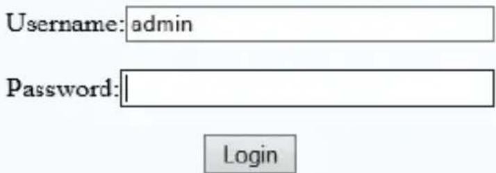
The media converter can be configured via a web console, accessible through any web browser by using its IP address.
- Open your desired web browser and enter the IP address for the device into the address bar (Default IP: 10.1.1.1).

- Enter the username / password (Default: admin / admin) and click Login.
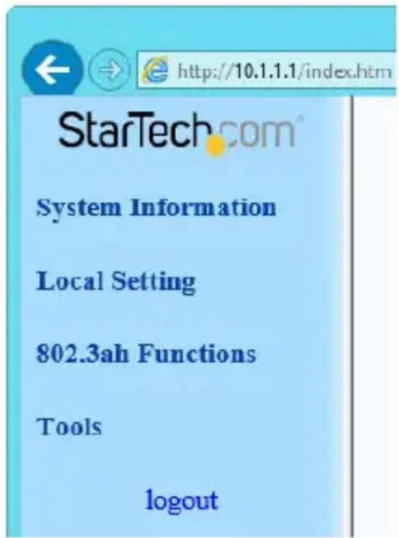
StarTech.com
1G Base-TX to 1G Base-FX OAM Media Converter
The configuration webpage will appear with the following section down the left side. Each can be expanded to reveal several configuration options and tool, which will be explained in the following pages
System Information Section
Network Information
The information displayed on this page gives specific device information, network information, and port status for the local ET91000LCOAM and for any remote unit that is accessible via IEEE802.3ah OAM in-band management.
Local Device Information
| BAC Address | 00:01:02:03:04:99 |
| Software Version | 1.000 |
| IP Address | 192.168.0.250 |
| Gateway | 192.168.0.10 |
| SuzmaF Stack | 255.255.255.0 |
| Description | ET91000LCOAN |
Remote Device Information
| MAC Address | 00:01:02:03:04:73 |
| Software Version | 1.000 |
| IP Address | 192.168.0.240 |
| Gateway | 192.168.0.10 |
| Socket Mask | 255.255.255.0 |
| Description | ET91000LCOAM |
Local Port Status
| Ports | TP | FX |
| Link States | Up | Up |
| Speed | 100M | 1000M |
| Duplex mode | Full | Full |
| Flow-control | Enable | Enable |
| Aide negotiation | Auto | Force |
Remote Port Status
| Ports | TP | FR |
| Link States | Down | Up |
| Special | 10M | 1000M |
| Duplex mode | Half | Full |
| Flow control | Enable | Enable |
| Auto-pegulation | Auto | Auto |
DD Information
The DD or DDOM information is read from the MSA compliant SFP module and can be displayed via the web user interface.
| Vendor Name11 | CTC UNION |
| Vendor Part Number | SFM-7000-S85(1) |
| Fiber type | Multi Mode |
| TX Wave Length | 0850 nm |
| RX Wave Length | 0850 nm |
| Link Length | 0550 m |
Local Settings Section
IP Configuration
Use this screen to configure TCP/IP settings for the local unit. Click the Apply button to save your settings.
Note: Changing the IP address will cause you to lose your remote management session until you re-connect at the new address.
| DHCP Client | Disable | |
| IP Address | 10.1.1.1 | |
| Subnet Mask | 255.255.255.0 | |
| Gateway | 10.1.1.254 | |
| Description | ET91000LCOAM |
Apply
Password Settings
Use this screen to change the web console login password. Key in the current password (Default: admin) and then enter your desired new password twice. Click the Apply button to save your settings.
| Login Name | admin | |
| Old Password | ||
| New Password | ||
| Confirm |
Apply
Converter Configuration
The Converter configuration menu includes special features of the ET91000LCOAM, defined below. Click the Apply button to save your settings.
| Management | ○ Disable ● Enable |
| Jumbo Frame (9K) | ● Disable ○ Enable |
| Link Loss Carry Forward | ● Disable ○ Enable |
| Auto Laser Shutdown | ● Disable ○ Enable |
| Forward CRC Error Frame | ● Drop ○ Forward |
| Forward Pause Frame | ● Drop ○ Forward |
| Management Packet High Priority (This function need reset to take effect!) | ○ Disable ● Enable |
| Broadcast Storm Filter | ● Disable ○ Enable |
| Multicast Storm Filter | ● Disable ○ Enable |
| Unknown DA Unicast Storm Filter | ● Disable ○ Enable |
Apply
Management - (Default: Enabled) If disabled, all management communication with a remote converter will be stopped. Only normal Ethernet transmission will occur without any possibility of remote management through 802.3ah OAM.
Jumbo Frames (9k byte packets) – (Default: Disabled) Enable to add Jumbo Frame support.
Note: Jumbo frames can only work on a pure Jumbo frame network where all devices support it.
Auto Laser Shutdown (ALS) - A safety mechanism that will disable laser output when no received optical signal is sensed. By default, ALS is disabled.
Link Loss Carry Forward – (Default: Disabled) A method of forwarding a link loss from copper to fiber or from fiber to copper.
Forward CRC Frame – (Default: Disabled) The normal behavior of a switch is to read the entire Ethernet frame (store), calculate the check sum and compare to the FCS in the packet. If the checksum matches, the packet is transmitted (&forward). If the checksum does not match, the switch considers the packet to have CRC error and drops it. If this option is enabled, the packet with CRC error will still be forwarded instead of being dropped.
Forward Pause Frame - (Default: Disabled) Enable to allow pause frame forwarding to occur. Pause frames are special broadcast frames defined in IEEE802.3x, normally used by the switch to throttle packets through a bottleneck rather than drop excess packets (E.g. A 1Gbps stream is exiting a 100Mbps port). Normally, pause frames are not forwarded between interfaces in the switch.
Management Packet High Priority – (Default: Enabled) Provides Quality of Service (QoS) functions to maintain a certain level of performance for specific applications (E.g. Voice and Video over IP). In Ethernet, QoS is dependent on VLAN tagged packets. This is because the QoS priority bits (3 bits) are included in the VLAN tag. Without VLAN tags, there are no priority bits, and no way to set QoS Priority. QoS Priority is enabled by default, but if there are no VLAN tagged packets, the enabled setting is meaningless.
Broadcast Storm Filter - (Default: Disabled) Enable to recognize and block the forwarding of excessive broadcast traffic. Broadcast Storm is a condition where either a loop exists on the network or an Ethernet transceiver is bad and exhibiting jabber.
Multicast Storm Filter - (Default: Disabled) Enable to block multicast traffic. Many applications like video streaming, IP punch clocks, etc. come with multicast or some broadcast-based protocol turned on by default. Multicast storms happen when application participants request re-transmits of information they have missed.
Unknown DA Unicast Storm Filter - (Default: Disabled) Enable to block unknown unicast traffic flooding at a specific port.
Port Configuration
Use this screen to configure the Ethernet (TP) and the optical port (FX). Options include enabling / disabling the port, setting auto or forced Ethernet mode, enabling 802.3x (flow control), and setting ingress and egress rate limiting.
Note: Rate limiting has a granularity of 64K so the rate can be set from 64k to 1000M in 64K steps.
Click the Apply button to save your settings.
| Port | Link | Port Active | Mode | Flow Control | Ingress Rate Limit (bps) | Egress Rate Limit (bps) | ||||||
| TP | Down | Enable | Auto Speed | Enable | Not Limit | ✓ | 0 | = 64k | Not Limit | ✓ | 0 | = 64k |
| FX | 1000F | Enable | Auto Speed | Enable | Not Limit | ✓ | 0 | = 64k | Not Limit | ✓ | 0 | = 64k |
Apply Refresh
MIB Counters
Reports packet statistics on all interfaces of the device.
| Port | TP | FX | CPU |
| Total Bytes | 0 | 83052 | 64339 |
| Total Pkts | 0 | 652 | 189 |
| Total Error Pkts | 0 | 0 | 0 |
| Unicast Pkts | 0 | 173 | 149 |
| Multicast Pkts | 0 | 332 | 0 |
| Broadcast Pkts | 0 | 147 | 40 |
| 64 | 0 | 148 | 134 |
| 65-127 | 0 | 392 | 9 |
| 128-255 | 0 | 57 | 3 |
| 256-511 | 0 | 40 | 4 |
| 512-1023 | 0 | 9 | 5 |
| 1024-1518 | 0 | 6 | 34 |
| Undersize Pkts | 0 | 0 | 0 |
| Oversize Pkts | 0 | 0 | 0 |
| Fragments | 0 | 0 | 0 |
| CRC Errors | 0 | 0 | 0 |
| Jabbers | 0 | 0 | 0 |
| Drop Events | 0 | 0 | 4 |
| Pause Frames | 0 | 0 | 0 |
Clear Refresh
VLAN
Group Configuration
ET91000LCOAM supports up to 16 VLAN groups. By using the check boxes for each port, the access to different VIDs can be controlled. Click the Apply button to save your settings.
| VLAN Mode | Disable |
| VLAN Group | VID | Member | ||
| TP | FX | CPU | ||
| 0 | 1 | ☑ | ☑ | ☑ |
| 1 | 1 | ☑ | ☑ | ☑ |
| 2 | 1 | ☑ | ☑ | ☑ |
| 3 | 1 | ☑ | ☑ | ☑ |
| 4 | 1 | ☑ | ☑ | ☑ |
| 5 | 1 | ☑ | ☑ | ☑ |
| 6 | 1 | ☑ | ☑ | ☑ |
| 7 | 1 | ☑ | ☑ | ☑ |
| 8 | 1 | ☑ | ☑ | ☑ |
| 9 | 1 | ☑ | ☑ | ☑ |
| 10 | 1 | ☑ | ☑ | ☑ |
| 11 | 1 | ☑ | ☑ | ☑ |
| 12 | 1 | ☑ | ☑ | ☑ |
| 13 | 1 | ☑ | ☑ | ☑ |
| 14 | 1 | ☑ | ☑ | ☑ |
| 15 | 1 | ☑ | ☑ | ☑ |
Apply
Per Port Configuration
ET91000LCOAM actually has three different ports: the external copper, external fiber, plus the internal CPU port. The VLAN Per Port Setting page deals with how frames exit (egress) the copper, fiber and CPU (management).
| Port | Egress Link Type | Port VLAN Entry |
| TP | Dont Touch Tag | 0 |
| FX | Dont Touch Tag | 0 |
| CPU | Dont Touch Tag | 0 |
The following operations may be performed to the outgoing frames:
- Replace Tag - The device will remove VLAN tags from packets then add new tags to them. The inserted tag is defined in "VLAN Group Index".
- Remove Tag - The switch will remove VLAN tags from packets, if they are tagged. The switch will not modify packets received without tags.
- Add Tag - The switch will add VLAN tags to packets, if they are not tagged when these packets are output on this port. The switch will not add tags to packets already tagged. The inserted tag is defined in "VLAN Group Index".
- Don't Touch Tag - Do not insert or remove VLAN tags to/from packet which is output on this port.
Double VLAN (Q-in-Q)
Use this section to Enable Q-in-Q tagging and adjust associated settings.
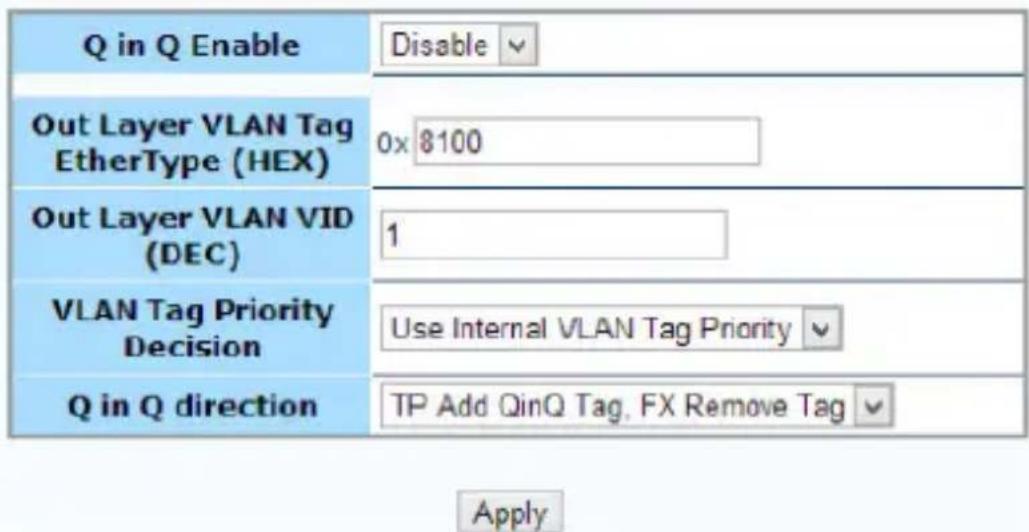
Q in Q or double VLAN tagging is defined in IEEE802.1ad. Double VLAN tagging is required when a service provider wishes to carry a customer's VLAN tagged traffic through its own VLAN network. In MEF (Metro Ethernet Forum) terms, the first tag or "inner tag" is referred to as the C-tag (customer) while the second tag or "outer tag" is referred to as the S-tag (service provider). Normal VLAN tag has an EtherType (TPID or Tag Protocol Identifier) of 0x8100. The IEEE802.1ad standard recommends 0x88a8 TPID for the outer or S-tag. Click the Apply button to save your settings.
Management VLAN
Use this section to configure a management VLAN and designate which ports it can be accessed from.
Click the Apply button to save your settings.
| Utp Port Access Control | ● Disable | ○ Enable | ○ Drop |
| Fiber Port Access Control | ● Disable | ○ Enable | ○ Drop |
| Management VID | 1 (1~4094) | ||
| Apply | |||
802.3ah Functions Section
This converter supports IEEE 802.3ah, an OAM protocol that operates at Ethernet Layer 2 (Data Link layer). OAM provides mechanisms to monitor link operation / health and to improve fault isolation.
OAM only works point-to-point over the fiber link. In addition to standard 802.3ah functions like loop back and dying gasp, ET91000LCOAM also implements OAM to provide complete provisioning of the remote fiber connected converter, without using Layer 3 IP protocol. By using OAM, we can remote manage another fiber connected converter, without IP addressing.
802.3ah Configuration
Use this section to configure OAM communication settings. Click the Apply button to save your settings.
| 802.3ah Function | ○Disable | ◎Enable |
| 802.3ah Mode | ◎Passive | ○Active |
| Link Events | ○Disable | ◎Enable |
| Remote Loopback | ○Disable | ◎Enable |
| Unidirection Support | ◎Disable | ○Enable |
| Errfrm_Win(second) | 2 | (1~60) |
| Errfrm_Thr | 1 | (1~2^32) |
| Errfrmprd_Win | 148800 | (1~2^32) |
| Errfrmprd_Thr | 5 | (1~2^32) |
| Errfrmsec_Win(second) | 10 | (10~900) |
| Errfrmsec_Thr | 5 | (1~65535) |
| Apply | ||
Note: To use the OAM functions, the 802.3ah Functions setting must be Enabled (Default: Disabled).
802.3ah Mode – (Default: Passive) Used to configure an OAM pair. In a pair, one unit must be 'active', while the other must be 'passive'. Typically the remote converter (CPE) would be in 'passive' mode and the local in 'active'.
Link Events – Enable / Disable reporting of Link Events via OAM.
Remote Loopback – (Default: Disabled) In order to do a Remote Loop Back test, the option must be enabled in both converters.
Unidirection Support – Enable / Disable reporting if Unidirectional Link Detection events via OAM.
Errfrm_Win (Error Frame Window) – (Default: 2 seconds) Adjustable from 1 to 60 seconds. This is the "Window" of time used to gather error frames.
Errfrm_Thr (Error Frame Threshold) - This threshold count can be set from 1 up to 2 x 1032. This count in conjunction with the error frame window, will determine if the Error Frame event is reported via OAM.
Errfrmprd_Win (Error Frame Period Window) – (Default: 148800) This frame count window can be set from 1 up to 2 x 1032 to gather the number of frame errors within the last x frames.
Errfrmprd_Thr (Error Frame Period Threshold) - This threshold count can be set from 1 up to 2 x 1032. This count in conjunction with the frame window will determine if the Error Frame Period event is reported via OAM.
Errfrmsec_Win (Error Frame Seconds Summary Window) – (Default: 10) This window of time can be adjusted from 10 to 900 seconds. This is the "Window" used to gather error frame seconds (the number of 1-second intervals with at least one frame error).
Errfrmsec_Thr (Error Frame Seconds Summary Threshold) - This threshold count can be set from 5 up to 2 x 10¹⁶. This count in conjunction with the frame seconds window, will determine if the Error Frame Seconds Summary event is reported via OAM.
Loopback Test
The loop back test is a non-intrusive test which uses OAM packets and will not affect normal transmissions.
| Send Packet Number | 1 | (1~255) |
| Packet Length(Not include CRC) | 60 | (60~1514) |

Send Packet Number – (Default: 1) The number of OAM frames used (the number of times the loop back is done).
Packet Length (Not including CRC) – (Default: 60 bytes) Controls the packet size of the OAM frames used for loop back testing. The CRC of Ethernet packets uses 4 bytes. Valid Ethernet packets range in size from 64 - 1518 bytes. VLAN tag adds another 4 bytes and Q in Q adds yet another 4 bytes, bringing the packet size to a maximum of 1526 bytes. Any frame size larger than this is technically called a jumbo frame.
802.3ah Status
The Global Config fields display the state of OAM (if Enabled). We can also see the MAC addresses of the local and remote units in the OAM manageable pair.
The Flags Field list the results of individual events based on the results of OAM protocol data units (OAMPDUs).
Lastly, when two OAM devices start negotiation, there is Discovery Information passed between them. The results are shown here.
Global Config
| Function Enable | ENABLED |
| Fiber Port State | NORM FWD |
| Local DTE MAC | 00-01-02-03-04-05 |
| Remote DTE MAC | 00-02-AB-FF-01-01 |
Flags Field
| Local | Remote | |
| Remote Stable | TRUE | TRUE |
| Remote Evaluating | FALSE | FALSE |
| Local Stable | TRUE | TRUE |
| Local Evaluating | FALSE | FALSE |
| Critical Event | FALSE | FALSE |
| Dying Gasp | FALSE | FALSE |
| Link Fault | FALSE | FALSE |
Discovery Information
| Discovery State | SEND_ANY |
| Local PDU | ANY |
| Local Satisfied | TRUE |
| Remote State Valid | TRUE |
| Local Last Link Timer Done | FALSE |
| Local Link Status | TRUE |
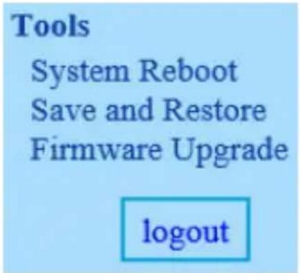
Tools Section
System Reboot
When the converter is rebooted, all counters and registers are cleared and the converter starts fresh. If OAM is enabled, the discovery process will start. After selecting the System Reboot menu item, a confirmation dialogue box will pop up. Click "OK" to reboot the converter or click "Cancel" to leave without rebooting.
Note: The converter requires about 20\~25 seconds to fully reboot.

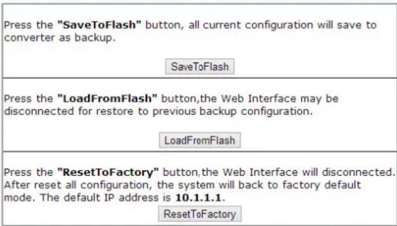
Save and Restore
After configuring the converter, the entire configuration can be saved as a backup file using the SaveToFlash button. Once saved, the configuration file can be loaded at any time using the LoadFromFlash button.
To restore all settings to factory default, click the ResetToFactory button.
Note: The IP address will also be reset to default (10.1.1.1), so you may lose management contact with the converter.
Firmware Upgrade
Use this section to upload a new firmware for added features, bug fixes or default setting changes.
Note: Please avoid loss of power or network connection during this process, to avoid damage to the device.

Upgrade
(Firmware Upgrading may take 60 seconds)
Firmware Upgrade process must NOT be interrupted!
Logging Out
Click the Logout button at the bottom of the web interface to terminate your session. Once logged out, the username / password will be required to login again.
Technical Support
StarTech.com's lifetime technical support is an integral part of our commitment to provide industry-leading solutions. If you ever need help with your product, visit www.startech.com/support and access our comprehensive selection of online tools, documentation, and downloads.
For the latest drivers/software, please visit www.startech.com/downloads
Warranty Information
This product is backed by a two year warranty.
In addition, StarTech.com warrants its products against defects in materials and workmanship for the periods noted, following the initial date of purchase. During this period, the products may be returned for repair, or replacement with equivalent products at our discretion. The warranty covers parts and labor costs only. StarTech.com does not warrant its products from defects or damages arising from misuse, abuse, alteration, or normal wear and tear.
Limitation of Liability
In no event shall the liability of StarTech.com Ltd. and StarTech.com USA LLP (or their officers, directors, employees or agents) for any damages (whether direct or indirect, special, punitive, incidental, consequential, or otherwise), loss of profits, loss of business, or any pecuniary loss, arising out of or related to the use of the product exceed the actual price paid for the product. Some states do not allow the exclusion or limitation of incidental or consequential damages. If such laws apply, the limitations or exclusions contained in this statement may not apply to you.
Hard-to-find made easy. At StarTech.com, that isn't a slogan. It's a promise.
StarTech.com is your one-stop source for every connectivity part you need. From the latest technology to legacy products — and all the parts that bridge the old and new — we can help you find the parts that connect your solutions.
We make it easy to locate the parts, and we quickly deliver them wherever they need to go. Just talk to one of our tech advisors or visit our website. You'll be connected to the products you need in no time.
Visit www.startech.com for complete information on all StarTech.com products and to access exclusive resources and time-saving tools.
StarTech.com is an ISO 9001 Registered manufacturer of connectivity and technology parts. StarTech.com was founded in 1985 and has operations in the United States, Canada, the United Kingdom and Taiwan servicing a worldwide market.


- In-Band OAM Gigabit Ethernet to MM LC Fiber Media Converter - 550m, Metal Housing
- FCC Compliance Statement
- Use of Trademarks, Registered Trademarks, and other Protected Names and Symbols
- Table of Contents
- Product Overview .... 1
- Introduction......2
- Factory Reset Procedure 2
- Installation ....3
- Operation 4
- Specifications....18
- Technical Support 19
- Warranty Information....19
- Product Overview
- Introduction
- Packaging Contents
- System Requirements
- Factory Reset Procedure
- Installation
- Installation into ETCHS2U Chassis
- Operation
- StarTech.com
- System Information Section
- Network Information
- DD Information
- Local Settings Section
- IP Configuration
- Password Settings
- Converter Configuration
- Port Configuration
- MIB Counters
- VLAN
- Group Configuration
- Per Port Configuration
- Double VLAN (Q-in-Q)
- Management VLAN
- 802.3ah Functions Section
- 802.3ah Configuration
- Loopback Test
- 802.3ah Status
- Tools Section
- System Reboot
- Save and Restore
- Firmware Upgrade
- Logging Out
- Technical Support
- Warranty Information
- Limitation of Liability
Brand : StarTech.com
Model : ET91000LCOAM
Category : Unspecified