99-7510HG - Unspecified AXESS - Free user manual and instructions
Find the device manual for free 99-7510HG AXESS in PDF.

User questions about 99-7510HG AXESS
0 question about this device. Answer the ones you know or ask your own.
Ask a new question about this device
Download the instructions for your Unspecified in PDF format for free! Find your manual 99-7510HG - AXESS and take your electronic device back in hand. On this page are published all the documents necessary for the use of your device. 99-7510HG by AXESS.
USER MANUAL 99-7510HG AXESS
• DIN radio provision with pocket
• ISO DIN radio provision with pocket
- Two finishes available: 99-7510 = Black
99-7510HG = Gloss Black
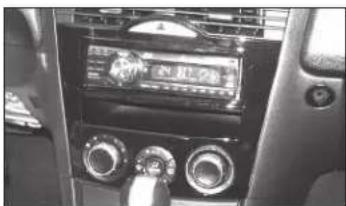
natural_image
Interior view of a car dashboard with steering wheel, air conditioners, and control knobs (no visible text or symbols)KIT COMPONENTS
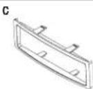
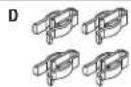
• A) Radio/climate control housing • B) ISO DIN brackets • C) ISO DIN trim plate • D) (4) Plastic panel clips
• E) Axxess Interface and wiring harness (not shown)


WIRING & ANTENNA CONNECTIONS
Wiring Harness: • Axxess interface and wiring harness included Antenna Adapter: • Not required
Table of Contents
Dash Disassembly 2
Kit Preparation....3-4
Kit Assembly
- DIN radio provision with pocket....4
- ISO DIN radio provision with pocket......5
Axxess Interface Installation ....5-7
Display Customization....7-8
TOOLS REQUIRED
- Panel removal tool • Phillips screwdriver
- 10mm socket wrench • Cutting tool
CAUTION! All accessories, switches, climate controls panels, and especially air bag indicator lights must be connected before cycling the ignition. Also, do not remove the factory radio with the key in the on position, or while the vehicle is running.

99-7510
Dash Disassembly
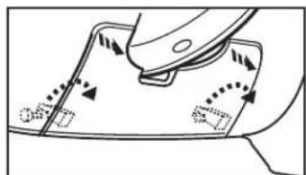
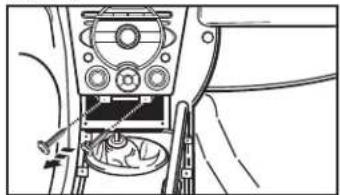
- Unscrew the shift knob counter clockwise to remove. (Figure A)
- Unclip and remove the shifter trim panel. (Figure B)
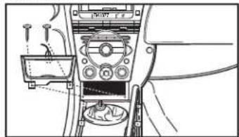
- Remove (2) Phillips screws from the bottom of the ashtray assembly, then unclip and remove. (Figure C)

natural_image
Line drawing of a hand using a tool to adjust or install a mechanical component (no text or symbols visible)(Figure A)
natural_image
Line drawing of a vehicle dashboard and steering wheel (no text or symbols)(Figure B)
natural_image
Interior view of a car dashboard and air intake unit (no text or symbols visible)(Figure C)
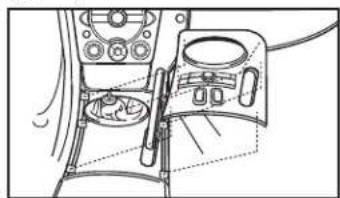
- Unclip and remove the knee panel on the driver's side under the steering column (Figure D)
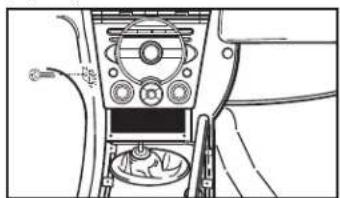
- Remove (1) 10mm bolt securing the side of the radio. (Figure E)
- Remove (2) Phillips screws from the bottom of the radio/climate control panel, then unsnap and remove. (Figure F)
Continue to Kit Preparation
natural_image
Diagram of a mechanical component with arrows indicating motion or movement, no readable text or symbols present(Figure D)
natural_image
Interior view of a car dashboard and infotainment system (no text or symbols visible)(Figure E)

natural_image
Interior view of a car dashboard with control panel and cable connector (no visible text or symbols)(Figure F)

99-7510
Kit Preparation
From the factory radio/climate control panel:
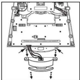
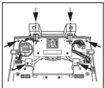
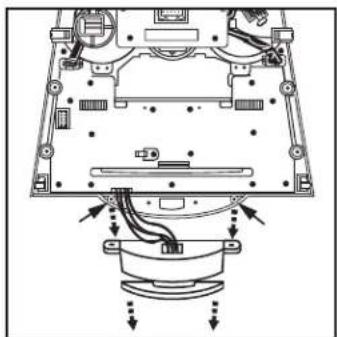
- Remove (3) screws securing the display harness. This harness will be reused in kit assembly. (Figure H)
- Remove (4) screws securing the radio chassis, and then remove. (Figure I)

natural_image
Mechanical assembly diagram showing a motor with attached cable and connector (no text or symbols)(Figure H)
- Remove (6) screws securing the climate controls, and then remove. The controls and hardware will be reused in kit assembly. (Figure J)
- Remove (17) screws securing the circuit board to access the hazard switch assembly. (Figure K)
- Remove (2) screws securing the hazard switch assembly. Carefully pull and release the hazard switch button from the assembly to fully remove the complete assembly. The switch and hardware will be reused in kit assembly. (Figure L)
Continue to the next page

natural_image
Technical diagram of a computer monitor with internal components and directional arrows indicating motion (no text or labels)(Figure K)

text_image
REMOVE (2) SCREWS PER SIDE(Figure I)

natural_image
Top-down schematic of a mechanical device with labeled components and arrows indicating assembly or movement (no readable text or symbols)(Figure J)
natural_image
Technical diagram of a mechanical assembly with labeled components and directional arrows (no text or symbols)(Figure L)

99-7510
Kit AssemblyKit Preparati
To the 99-7510 radio/climate control housing:
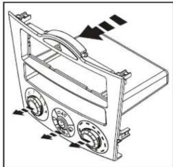
- Cut the top (2) mounting locations off of the climate controls to provide clearance for the aftermarket radio. (Figure A)
- Secure the climate controls using the factory hardware. (Figure B)
- Secure the hazard switch assembly using the factory hardware. Push the hazard switch button back into the assembly. (Figure B)
- Attach the (4) plastic panel clips provided.
Continue to Kit Assembly

natural_image
Line drawing of a robotic vehicle with multiple dome-shaped components and attached sensors (no text or symbols)(Figure A)

natural_image
Technical line drawing of a mechanical housing or enclosure with mounting flanges and directional arrows indicating motion (no text or symbols)(Figure B)
DIN radio provision with pocket
- Remove the metal DIN sleeve from the aftermarket radio.
- Slide the sleeve into the radio/climate control housing and secure by bending the metal locking tabs outward. (Figure A)
- Slide the radio into the sleeve until it clicks in. (Figure B)
Continue to Axxess Interface Installation

natural_image
Line drawing of a hand using a tool to adjust or install electronic components on a device (no text or symbols visible)(Figure A)

natural_image
Technical line drawing of a mechanical device with no visible text or symbols(Figure B)
Kit Assembly
ISO DIN radio provision with pocket
- Remove the metal DIN sleeve and trim ring from the aftermarket radio.
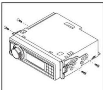
- Secure the ISO DIN brackets to the radio using the screws supplied with the radio. (Figure A)
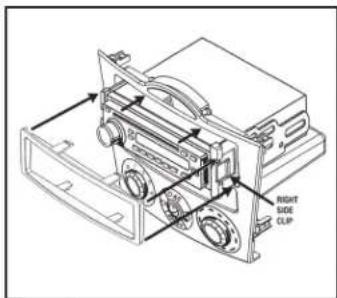
- Slide the radio into the radio/climate control housing until it snaps into place. (Figure B)
- Snap the ISO DIN trim plate into the radio/climate control housing. (Figure B)
Continue to Axxess Interface Installation
natural_image
Technical line drawing of a computer case with ports and buttons (no text or symbols)(Figure A)

text_image
RIGHT SIDE CLIP(Figure B)
Axxess Interface Installation
TABLE OF CONTENTS
Connections to be made....6
Installing the interface 7
Display Customization....7-8
INTERFACE FEATURES
- Provides NAV outputs (parking brake, reverse, speed sense)
- Can be used in both amplified and non-amplified models
• Retains balance and fade
• USB-CAB updatable (sold separately)
INTERFACE COMPONENTS
- 7510 harness • OBDII harness with stripped leads
- Hazard switch extension cable
- Climate control extension harnesses (2)
TOOLS REQUIRED
- Wire Cutter • Crimp tool • Solder gun • Tape
- Connectors (example: butt-connectors, bell caps, etc.)

99-7510
Connections to be made
From the 7510 harness to the aftermarket radio:
- Connect the Black wire to the ground wire.
- Connect the Yellow wire to the battery wire.
- Connect the Red wire to the accessory wire.
- Connect the Blue wire to the power antenna wire.
- If the vehicle is equipped with a factory amplifier, connect the Blue/White wire to the amp turn on wire. This wire must be connected to hear sound from the factory amplifier.
- If the aftermarket radio has an illumination wire, connect the Orange wire to it.
- Tape off and disregard the Orange/White wire, it will not be used in this application.
- Connect the Gray wire to the right front positive speaker output.
- Connect the Gray/Black wire to the right front negative speaker output.
- Connect the White wire to the left front positive speaker output.
- Connect the White/Black wire to the left front negative speaker output.
- Connect the Green wire to the left rear positive speaker output.
- Connect the Green/Black wire to the left rear negative speaker output.
- Connect the Purple wire to the right rear positive speaker output.
- Connect the Purple/Black wire to the right rear negative speaker output.
The following steps are only for multimedia/navigation radios that require these wires.
- Connect the Blue/Pink wire to the VSS/speed sense wire.
- Connect the Green/Purple wire to the reverse wire.
Note: Not applicable on manual transmission vehicles. - Connect the Light Green wire to the parking brake wire.
- Connect the ODBII harness with stripped leads, to the 2-pin harness.
- Run the wires from ODBII harness with stripped leads to the ODBII connector in the vehicle, and then connect them as shown.

text_image
OBDII CONNECTOR FACE VIEW PINK WIRE 12 3 4 5 6 7 8 9 10 11 12 13 14 15 16 PINK/BLUE WIRE
99-7510
Installing the interface
Attention!: Failure to insert the HVAC cables into the correct location will cause damage to the interface and make the display and HVAC controls not function properly.
- Attach the (2) climate control extension harnesses to the temperature control cable, and the fan control cable, on the factory climate control.
- Plug the temperature control cable from the factory climate control into the port on the interface labeled "TEMP". (Figure A)
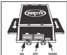
- Plug the fan control cable from the factory climate control into the port on the interface labeled "FAN". (Figure B)
- Plug the display harness removed in step 1 of kit preparation into the port on the interface labeled "DISP". (Figure B)
- Plug the hazard switch extension cable to the factory hazard switch, and then into the port on the interface labeled "HAZARD". (Figure B)
- Test all functions of the installation for proper operation, before reassembling the dash. Note: If the vehicle is equipped with automatic climate controls, start the vehicle and hold the "AUTO" button for 10 seconds to program the climate controls.
- Reassemble the dash in reverse order of disassembly

text_image
AXXESS TEMP(Figure A)
text_image
SSXXA FAN DISP HAZARD(Figure B)
Display Customization
- Press and hold the A/C Mode button to scroll through the various kit options (AMB TEMP ON or OFF, AMB TEMP C or F, SET TIME 12/24H, and SET TEXT).
- When you see the option you want just let the button go and the action on the screen will be performed. (ie: To turn the ambient temperature on you would scroll through until the display says "AMB TEMP ON" and let the button go.)
- To set the time hold down the A/C Mode button until the display says "SET TIME 12/24H" then let the button go.
- To switch between 12H and 24H press the front defrost button to the left of the A/C Mode button.
Continued on the next page

text_image
Diagram of a car air conditioning control panel with labeled buttons and dials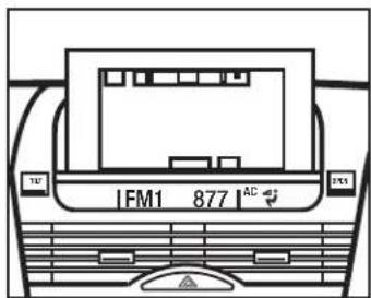
text_image
IFM1 877 AC
Installation instructions for part 99-7510

Display Customization (Cont)
- To change the Hour press the rear defrost button to the right of the A/C Mode button.
- To change the minute press the A/C button at the top of the A/C Mode button.
- At any time if you do not press any buttons for 5-seconds the display will save and return to the default screen and the climate control buttons will return to their normal configuration.
- If you hold the A/C Mode button down long enough the display will say "SET TEXT". This will allow you customize the default text on the display.
- Once the display says "SET TEXT" let go and the first letter of the display will begin blinking.
- Press the front defrost button to move the cursor left and the rear defrost button to move the cursor to the right.
- You can scroll up with the A/C button and down with the Recirc/Fresh button through the various alpha, numeric, and symbol characters.
- When you are finished entering your text if you do not press any buttons for 5-seconds the display will save and return to the default screen and the climate control buttons will return to their normal configuration.
IMPORTANT
If you are having difficulties with the installation of this product, please call our Tech Support line at 1-800-253-TECH. Before doing so, look over the instructions a second time, and make sure the installation was performed exactly as the instructions are stated. Please have the vehicle apart and ready to perform troubleshooting steps before calling.

KNOWLEDGE IS POWER
Enhance your installation and fabrication skills by enrolling in the most recognized and respected mobile electronics school in our industry. Log onto www.installerinstitute.com or call 800-354-6782 for more information and take steps toward a better tomorrow.

Metra recommends MECP certified technicians

natural_image
Interior view of a car dashboard with air conditioners and a digital display (no visible text or symbols)COMPONENTES DEL KIT
natural_image
Line drawing of a hand using a tool to adjust or install a mechanical component (no text or symbols visible)(Figura A)

natural_image
Line drawing of a vehicle dashboard and steering wheel (no text or symbols)(Figura B)

natural_image
Interior view of a car dashboard and air intake unit (no text or symbols visible)(Figura C)
natural_image
Diagram of a mechanical component with arrows indicating motion or movement, no visible text or symbols(Figura D)

natural_image
Interior view of a car dashboard and infotainment system (no text or symbols visible)(Figura E)
natural_image
Line drawing of a car interior showing dashboard, steering wheel, and gear shift (no text or symbols)(Figura F)

99-7510
Preparación del kit
natural_image
Mechanical assembly diagram showing a motor with attached cable and connector (no text or symbols)(Figura H)
natural_image
Technical diagram of a computer monitor with internal components and directional arrows indicating motion (no text or labels)(Figura K)

text_image
REMOVE (2) SCREWS PER SIDE(Figura I)
natural_image
Technical line drawing of a mechanical device with labeled components and arrows indicating assembly or movement (no text or symbols present)(Figura J)
natural_image
Technical diagram of a mechanical assembly with labeled components and directional arrows (no text or symbols)(Figura L)

99-7510
natural_image
Line drawing of a vehicle with multiple dome-shaped structures and a toolbar, no text or symbols present(Figura A)
natural_image
Technical line drawing of a mechanical housing or enclosure with mounting flanges and internal components (no text or symbols)(Figura B)
natural_image
Line drawing of a hand using a tool to adjust or install electronic components on a device (no text or symbols visible)(Figura A)

natural_image
Technical line drawing of a mechanical device with no visible text or symbols(Figura B)
Ensamble del kit
natural_image
Technical line drawing of a computer case with ports and buttons (no text or symbols)(Figura A)
text_image
RIGHT SIDE CLIP(Figura B)
text_image
AXCESS TEMP(Figura A)

text_image
SSexxx FAN DISP HAZARD(Figura B)
text_image
Diagram of a car dashboard with labeled controls and directional arrows indicating flow or movement.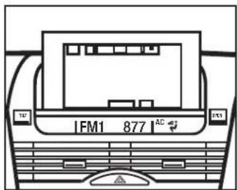
text_image
IFM1 877 AC