99-6536S - Kit d'installation audio voiture AXESS - Free user manual and instructions
Find the device manual for free 99-6536S AXESS in PDF.

User questions about 99-6536S AXESS
0 question about this device. Answer the ones you know or ask your own.
Ask a new question about this device
Download the instructions for your Kit d'installation audio voiture in PDF format for free! Find your manual 99-6536S - AXESS and take your electronic device back in hand. On this page are published all the documents necessary for the use of your device. 99-6536S by AXESS.
USER MANUAL 99-6536S AXESS
natural_image
Interior view of a car dashboard with digital displays and control panels (no visible text or symbols)Jeep Grand Cherokee 2014-2021
Visit MetraOnline.com for more detailed information about the product and up-to-date vehicle specific applications
KIT FEATURES
• ISO DIN radio provision with pocket
- ISO DDIN radio provision
- Retains audio controls on the steering wheel
- Retains the factory backup camera
- Touchscreen display for climate and personalization features
- Painted: Bronze - 99-6536BZ, Silver - 99-6536S
KIT COMPONENTS
- A) Radio trim panel with touchscreen display • B) Radio brackets • C) Pocket • D) #8 x 3/8" Phillips screws (4) • E) Panel clips (10)
• F) Wiring harness (not shown) • G) Antenna adapter (not shown)

natural_image
Line drawing of a car front panel with no text or symbols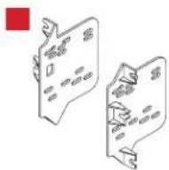


Product Info

TABLE OF CONTENTS
Dash Disassembly....2
Kit Preparation....3
Kit Assembly
-ISO DIN radio provision with pocket....4
-ISO DDIN radio provision 4
Axxess Interface Installation 5-14
Final Assembly 9
WIRING & ANTENNA CONNECTIONS
Wiring Harness: Axxess interface built into touchscreen
Antenna Adapter: Included with kit
TOOLS REQUIRED
• Panel removal tool • Phillips screwdriver
- 9/32" Socket wrench • 5.5mm Socket wrench
ATTENTION: With the key out of the ignition, disconnect the negative battery terminal before installing this product. Ensure that all installation connections, especially the air bag indicator lights, are plugged in before reconnecting the battery or cycling the ignition to test this product.
NOTE: Refer also to the instructions included with the aftermarket accessory before installing this device.
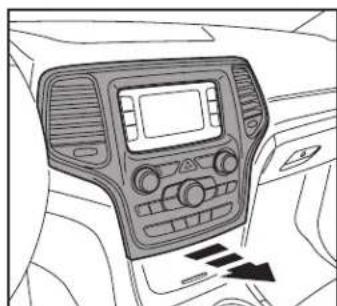
DASH DISASSEMBLY
- Using the panel removal tool, gently unclip, unplug, and remove the climate control panel. (Figure A)
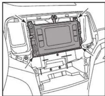
- Remove (4) 9/32" screws securing the radio/display screen, and then unplug and remove. (Figure B)
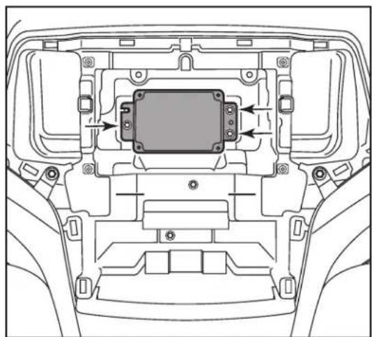
- Remove (3) 5.5mm screws securing the black control module in the sub-dash, and then relocate lower to allow clearance for the aftermarket radio. (Figure C)
Continue to Kit Preparation
natural_image
Interior view of a car dashboard with air conditioner and directional arrows (no text or symbols)(Figure A)
natural_image
Line drawing of a vehicle interior showing the front panel and dashboard (no text or symbols)(Figure B)
natural_image
Technical line drawing of a vehicle interior showing internal components and directional arrows (no text or symbols)(Figure C)
KIT PREPARATION
From the factory radio/climate control panel:
- Unclip the A/C vents from the back of the panel. (Figure A)
To the 99-6536 radio trim panel:
-
Attach the A/C vents to the back of the panel. (Figure B)
-
Attach the (10) panel clips provided in this kit to the clips on the back of the panel.
Continue to Kit Assembly

natural_image
Top-down schematic of a vehicle dashboard with front and rear compartments, showing no text or symbols(Figure A) (Figure B)

natural_image
Technical line drawing of a car dashboard and internal air vent (no text or symbols)KITASSEMBLY
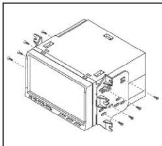
ISO DIN radio provision with pocket
- Attach the pocket to the radio brackets using the (4) #8 x 3/8" Phillips screws provided in this kit. (Figure A)
- Remove the metal DIN sleeve and trim ring from the aftermarket radio.
- Slide the radio into the bracket/pocket assembly, and then secure it using the screws supplied with the radio. (Figure B)
Continue to Axxess Interface Installation

natural_image
Technical line drawing of a mechanical component with mounting holes and internal brackets (no text or symbols)(Figure A)
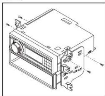
ISO DDIN radio provision
- Attach the radio brackets to the radio using the screws supplied with the radio. (Figure A)
- Reconnect the negative battery terminal and prepare for the Axxess interface installation.
Continue to Axxess Interface Installation
natural_image
Technical line drawing of a device housing with internal components and mounting holes (no text or symbols)(Figure A)
natural_image
Technical line drawing of a mechanical device with labeled components (no text or symbols present)(Figure B)
AXXESS INTERFACE INSTALLATION
INTERFACE FEATURES
- Designed for amplified and non-amplified models
- Provides accessory power (12-volt 10-amp)
• Retains R.A.P. (retained accessory power) - Provides NAV outputs (parking brake, reverse, speed sense)
- Retains audio controls on the steering wheel
- Retains safety chimes
- Retains the factory backup camera
- Retains the factory AUX-IN jack
- Retains balance and fade (in non-amplified models only)
- USB Micro-B updatable
INTERFACE COMPONENTS
- Axxess interface (built into the touchscreen display)
• 6536 harness
• 16-pin harness with stripped leads
• 4-pin harness with yellow RCA jacks
• Hazard harness (LD-CHRYHAZ2)
• Female 3.5mm connector with stripped leads
TABLE OF CONTENTS
Connections
For Models without an Amplifier 6
For Models with an Amplifier....7
3.5mm Jack Steering Wheel Control Retention 8
Installation 9
Programming....9
Final Assembly 9
Touchscreen Display Operation....10-11
Steering Wheel Control Settings 12-13
Troubleshooting....14
TOOLS REQUIRED
- Wire cutter
- Crimp tool and connectors (example: butt-connectors, bell caps, etc.) or
- Solder gun, solder, and heat shrink
- Tape
- Zip-ties
- Small flat-blade screwdriver
CONNECTIONS
Attention! This interface will work with models that are either non-amplified, or amplified. Please follow the instructions carefully for your model vehicle. Failure to do so will result in either no sound, or low sound. If you are unsure if your vehicle is factory amplified or not, please contact your local dealership.
For Models Without a Factory Amplifier:
From the 16-pin harness with stripped leads to the aftermarket radio, connect as indicated:
- Red wire to the accessory wire.
- Orange/White wire to the illumination wire. (if applicable)
- Green wire to the left rear (+) speaker output.
- Green/Black wire to the left rear (-)speaker output.
- Purple wire to the right rear (+) speaker output.
- Purple/Black wire to the right rear (-)output.
Tape off and disregard the following (6) wires, they will not be used in this application:
Blue/White, Brown, Gray, Gray/Black, White, White/Black
The following (3) wires are only for multimedia/navigation radios that require these wires.
• Blue/Pink wire to the VSS/speed sense wire.
- Green/Purple wire to the reverse wire.
• Light Green wire to the parking brake wire.
From the 6536 harness to the aftermarket radio, connect as indicated:
- Black wire to the ground wire.
- Yellow wire to the battery wire.
- Gray wire to the right front (+) speaker output.
- Gray/Black wire to the right front (-) speaker output.
- White wire to the left front (+) speaker output.
- White/Black wire to the left front (-)speaker output.
• The 4-pin connector from the 6536 harness to the 4-pin harness with Yellow RCA jacks.
- Yellow RCA jacks to the reverse camera input. (if retaining the factory backup camera)
- Red and White RCA jacks to the audio AUX-IN jacks of the aftermarket radio. (if using the AUX-IN jack in the dash)
Note: Disregard the DIN jack, it will not be used in this application.
Continue to 3.5mm jack steering wheel control retention
CONNECTIONS (CONT.)
Attention! This interface will work with models that are either non-amplified, or amplified. Please follow the instructions carefully for your model vehicle. Failure to do so will result in either no sound, or low sound. If you are unsure if your vehicle is factory amplified or not, please contact your local dealership.
For Models With a Factory Amplifier:
From the 16-pin harness with stripped leads to the aftermarket radio, connect as indicated:
- Red wire to the accessory wire.
- Blue/White wire to the amp turn on wire.
Note: This wire must be connected to hear sound from the factory amplifier.
- Orange/White wire to the illumination wire. (if applicable)
- Gray wire to the right front (+) speaker output.
- Gray/Black wire to the right front (-)speaker output.
- White wire to the left front (+) speaker output.
- White/Black wire to the left front (-)speaker output.
- Green wire to the left rear (+) speaker output.
- Green/Black wire to the left rear (-)speaker output.
• Purple wire to the right rear (+) speaker output. - Purple/Black wire to the right rear (-)output.
Tape off and disregard the following (1) wire, it will not be used in this application: Brown
The following (3) wires are only for multimedia/navigation radios that require these wires.
- Blue/Pink wire to the VSS/speed sense wire.
• Green/Purple wire to the reverse wire.
• Light Green wire to the parking brake wire.
From the 6536 harness to the aftermarket radio:
- Black wire to the ground wire.
- Yellow wire to the battery wire.
Tape off and disregard the following (4) wires, they will not be used in this application:
Gray, Gray/Black, White, White/Black
- The 4-pin connector from the 6536 harness to the 4-pin harness with Yellow RCA jacks.
- Yellow RCA jacks to the reverse camera input. (if retaining the factory backup camera)
- Red and White RCA jacks to the audio AUX-IN jacks of the aftermarket radio. (if using the AUX-IN jack in the dash)
Note: Disregard the DIN jack, it will not be used in this application.
Continue to 3.5mm jack steering wheel control retention
CONNECTIONS (CONT.)
3.5mm jack steering wheel control retention:
The 3.5mm jack is to be used to retain audio controls on the steering wheel.
- For the radios listed below: Connect the female 3.5mm connector with stripped leads to the male 3.5mm SWC jack from the 6536 harness. Tape off and disregard any remaining wires.
- Eclipse: Connect the steering wheel control wire, normally Brown, to the Brown/White wire from the connector. Then connect the remaining steering wheel control wire, normally Brown/White, to the Brown wire from the connector.
• Metra OE: Connect the Gray steering wheel control wire (Key 1) to the Brown wire. - Kenwood or select JVC with a steering wheel control wire: Connect the Blue/Yellow wire to the Brown wire.
Note: If your Kenwood radio auto detects as a JVC, manually set the radio type to Kenwood. See the instructions under changing radio type.
- XITE: Connect the steering wheel control SWC-2 wire from the radio to the Brown wire.
- Parrot Asteroid Smart or Tablet: Connect the 3.5mm jack into the AX-SWC-PARROT (sold separately), and then connect the 4-pin connector from the AX-SWC-PARROT into the radio. Note: The radio must be updated to rev. 2.1.4 or higher software.
- Universal "2 or 3 wire" radio: Connect the steering wheel control wire, referred to as Key-A or SWC-1, to the Brown wire from the connector. Then connect the remaining steering wheel control wire, referred to as Key-B or SWC-2, to the Brown/White wire from the connector. If the radio comes with a third wire for ground, disregard this wire.
Note: After the interface has been programmed to the vehicle, refer to the manual provided with the radio for assigning the SWC buttons. Contact the radio manufacturer for more information.
- For all other radios: Connect the 3.5mm jack from the 6536 harness to the jack on the aftermarket radio designated for an external steering wheel control interface. Please refer to the aftermarket radio's manual, if in doubt as to where the 3.5mm jack connects.
4-pin harness with yellow RCA jacks:
- If retaining the factory backup camera to the touchscreen display is desired, connect the Yellow RCA jack labeled "Rearview camera", to the Yellow RCA jack from the 6536 harness.
Note: If this method is chosen, the backup camera option must be enabled in the Settings screen.
- Disregard the Yellow RCA jack labeled "AUX video", it will not be used in this application.
INSTALLATIONPROGRAMM
ATTENTION: It is highly advisable to read the following steps beforehand, to ensure a clear understanding of what is to be expected. The following steps must be done in the order that they are numbered.
With the vehicle completely off:
- Locate the factory antenna connector in the dash and complete all necessary connections to the radio. Use the antenna adapter provided to adapt the factory antenna connector to the aftermarket radio.
- Connect the 16-pin harness with stripped leads into port "B" in the touchscreen display.
- Connect the 4-pin harness with Yellow RCA jacks into port "C" of the touchscreen display.
- Connect the hazard harness (LD-CHRYHAZ2) into port "D" of the touchscreen display, and then to the designated factory 8-pin in the vehicle.
Note: Be sure to plug in the 8-pin connector from the climate control. Plugging the wrong 2-pin connector to port "E" will jam the CANBUS.
- Connect the 2-pin connector labeled A into port "E".
- Port "F" is an update port for future firmware upgrades.
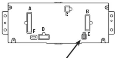
text_image
A C B F D ENote: For 2018-2021 models only, Connect the 2-pin connector labeled A into port "E"
G
- Connect the 6536 harness to the wiring harnesses in the vehicle. Then insert the 6536 harness into port "A" in the touchscreen display.
Note: This is a timed process. - Press the push-to-start button to start the vehicle.
- Program the Axxess interface built into the touchscreen display:
a. Once the touchscreen display loads up, select the vehicle type.
b. Wait until the radio comes on, and the touchscreen display shows SWC Configured. This process may take up to (3) minutes.
Note: If the touchscreen display does not load up, or the radio doesn't come on within (3) minutes, and/or the touchscreen display does not show SWC Configured, turn the vehicle off and disconnect the 6536 harnesses from port "A" in the touchscreen display. Check all the connections, reconnect the harness into the touchscreen display, and then try again.
- Cycle the key off, then back on. If the driver's door is closed, open and close the door.
- Refer to the Settings page within the Touchscreen Display Operation section. Ensure that all factory features have been selected properly according to the options available for the vehicle.
- Test all functions of the installation for proper operation, before reassembling the dash. Note: The clock and compass in the driver's information center will no longer be functional.
FINAL ASSEMBLY
- Mount the completed radio/climate control assembly in the dash using the screws supplied with the factory radio.
- Snap the radio trim panel with touchscreen display over the completed assembly, and then reassemble the dash in reverse order of disassembly.
Climate Control screen Heated/Cooled Seats screen
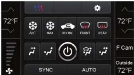
text_image
72°F A/C MAX RECIRC FRONT REAR SYNC AUTO 72°F F Cam Outside 72°F- This is the climate control screen which will be displayed on the touchscreen display. This is considered the Main Menu screen.
- The upper left tab with (3) arrows will take you to the Heated/Cooled Seats* screen, Heated Steering* screen, Mirror Dimming* screen, and also to the screen where the hard buttons that were on the factory radio panel are now placed.
- The upper right tab with a gear icon will take you to the Settings screen.
- The climate controls will function in the same manner that they did with the factory climate controls.
- For models with rear climate controls, the button labeled REAR will take you to the rear climate control menu.
* If applicable.
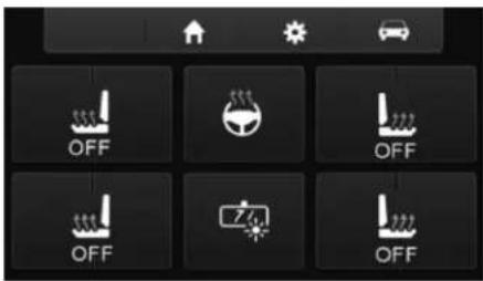
text_image
OFF OFF OFF OFF OFF- This is the Heated/Cooled Seats, Heated Steering, and Mirror Dimming screen which will be displayed on the touchscreen display.
- The upper left-middle tab with a home icon will take you back to the Main Menu screen.
• The upper right-middle tab with a gear icon will take you to the Settings screen. - The upper right tab with a car icon will take you to the screen where the hard buttons that were on the factory radio panel are now placed.
Continued on the next page
text_image
Settings Display Safety & Driving Assistance Lights Doors & Lock- Display
- Backlight - For controlling the color of the buttons and back-light intensity.
- Language
- Units
• Safety & Driving Assistance - Factory features
- Lights - Factory features
- Doors & Locks - Factory features

text_image
Settings Engine Off Options Steering Wheel Controls Digital Amp Gain System Config• Engine Off Options - Factory features
- Steering Wheel Controls
- Remap Buttons – For remapping the steering wheel control buttons
- Dual Assign – For dual assigning the steering wheel control buttons (long button press)
- Select Radio – For auto detecting the radio, or changing the radio type
- Digital Amp Gain - For adjusting the output gain to the amplifier
text_image
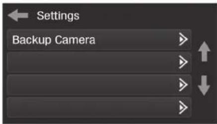
Settings Backup Camera- System Configuration
- About - Information regarding the software in the kit
- Reset Vehicle Type - To reset the kit to default settings
- Comfort Options Override - Provides the ability to disable/enable certain factory options
- Backup Camera
- Enable/disables the backup camera image to the touchscreen display. Disabled by default.
STEERING WHEEL CONTROL SETTINGS
Remap Button screen Dual Assign screen

text_image
Select Button For Remap Seek Up Seek Down Source/Mode Mute- The interface has the ability to change the button assignment for the steering wheel control audio buttons, except Volume-Up and Volume-Down. Follow the prompts on the touchscreen display to remap the steering wheel control audio button(s) to your liking.
Note: The aftermarket radio may not have all of these commands. Please refer to the manual provided with the radio, or contact the radio manufacturer, for specific commands recognized by that particular radio.
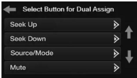
text_image
Select Button for Dual Assign Seek Up Seek Down Source/Mode Mute- The interface has the capability to assign two functions to a single button, except Volume-Up and Volume-Down. Follow the prompts on the touchscreen display to program the button(s) to your liking.
Note: Seek-Up and Seek-Down come programmed as Preset-Up and Preset-Down for a long button press.
Continued on the next page
STEERING WHEEL CONTROL SETTINGS (CONT.)
Select Radio screen
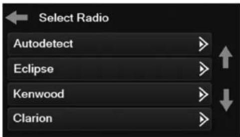
text_image
Select Radio Autodetect Eclipse Kenwood Clarion- To show which brand radio is "auto detected" to the interface, press the "Autodetect" button. The radio detected will have a filled in circle. If the incorrect radio is shown, select the proper radio.
Following is a list of radio manufacturers that the interface presently acknowledges. Others may be added at a later date. Universal "2 or 3 wire" radios can show up as any of these radio manufacturers.
| Radio |
| Eclipse (type 1) † |
| Kenwood ‡ |
| Clarion (type 1) † |
| Sony / Dual |
| JVC |
| Pioneer / Jensen |
| Alpine * |
| Visteon |
| Valor |
| Clarion (type 2) † |
| Metra OE |
| Eclipse (type 2) † |
| Radio |
| LG |
| Parrot ** |
| XITE |
| Philips |
| TBA |
| JBL |
| Insane |
| Magnadyne |
| Boss |
| Axxera |
| Axxerra (type 2) |
* Note: If the interface shows an Alpine radio, and you do not have an Alpine radio, that means the interface does not detect a radio connected it, i.e., an open connection. Verify that the 3.5mm jack is connected to the correct steering wheel jack/wire in the radio.
** Note: The AX-SWC-PARROT is required (sold separately). Also, the Parrot radio must be updated to rev. 2.1.4 or higher through www.parrot.com.
^ Note: If you have a Clarion radio and the steering wheel controls do not work, change the radio type to the other Clarion radio type; same for Eclipse.
† Note: If you have a Kenwood radio and the touchscreen display shows a JVC radio, change the radio type to Kenwood.
TROUBLESHOOTING
Resetting the Axxess interface
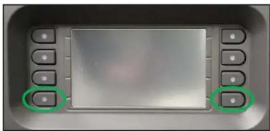
Option #1
- With everything connected and the car running.
- Hold the bottom (2) buttons for (3) seconds, then release. (Figure A) (The screen will turn black and then the vehicle selection screen will appear)
- Select your vehicle and wait till the "SWC Configured" appears on the screen.
- Turn the ignition off and restart the vehicle, then test the Axxess interface.
Option #2
- With the vehicle running, press the Reset Vehicle Type button located in System Configuration. This will reset the kit to default settings.
- Refer to Programming, step 3, from this point.
natural_image
Close-up of a control panel with buttons and a blank screen (no visible text or symbols)(Figure A)
Having difficulties? We're here to help.

act our Tech Support line at:
357-1187

mail at:
techsupport@metra-autosound.com
Tech Support Hours (Eastern Standard Time)
Monday - Friday: 9:00 AM - 7:00 PM
Saturday: 10:00 AM - 5:00 PM
Sunday: 10:00 AM - 4:00 PM

KNOWLEDGE IS POWER
Enhance your installation and fabrication skills to enrolling in the most recognized and respected
enabling in the most recognized and resp mobile electronics school in our industry.
Log onto www.installerinstitute.edu or call
386-672-5771 for more information and take steps toward a better tomorrow.

Metra recommends MECP
certified technicians