99-7803G - Car stereo AXESS - Free user manual and instructions
Find the device manual for free 99-7803G AXESS in PDF.

User questions about 99-7803G AXESS
0 question about this device. Answer the ones you know or ask your own.
Ask a new question about this device
Download the instructions for your Car stereo in PDF format for free! Find your manual 99-7803G - AXESS and take your electronic device back in hand. On this page are published all the documents necessary for the use of your device. 99-7803G by AXESS.
USER MANUAL 99-7803G AXESS
Installation instructions for part 99-78036
U.S. PATENT # D756.348
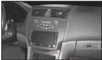
Honda Accord 2003-2007 99-78036
KIT FEATURES
• ISO DIN radio provision with pocket
• ISO DDIN radio provision
- Retains all climate control systems including dual-zone
- Painted gray to match the factory finish
natural_image
Interior view of a car dashboard with air conditioner and touchscreen (no visible text or symbols)KIT COMPONENTS
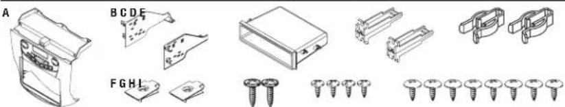
• A) Radio housing trim panel • B) Radio brackets • C) Pocket • D) Panel clip legs • E) (2) Panel clips
- F) (2) Speed clips • G) (2) #10 x 3/4" Phillips screws • H) (4) #4 x 3/8" Phillips pan-head screws
- I) (8) #8 x 3/8" Phillips truss-head screws • Wiring harness (not shown)
natural_image
Technical line drawings of various mechanical components and screw assemblies (no text or symbols)WIRING & ANTENNA CONNECTIONS (sold separately)
Wiring Harness: • Included with kit
Antenna Adapter: • Not Required
TOOLS REQUIRED
- Panel removal tool - Phillips screwdriver
Table of Contents
Dash Disassembly 2
Kit Preparation....3
Kit Assembly
- ISO DIN radio provision with pocket......4
- ISO DDIN radio provision 5
Axxess Interface Installation 6
Note: The door on the factory pocket below the radio will not function properly with the 99-7803G installed. As an alternate solution, Metra offers the 88-00-7803 replacement pocket (sold separately).
CAUTION! All accessories, switches, climate controls panels, and especially air bag indicator lights must be connected before cycling the ignition. Also, do not remove the factory radio with the key in the on position, or while the vehicle is running.

99-78036
Dash Disassembly
Attention! For auto-climate control models only. Turn the fan speed all the way up, and then turn the recirculation button off, prior to turning the vehicle off and removing the radio/climate control assembly.
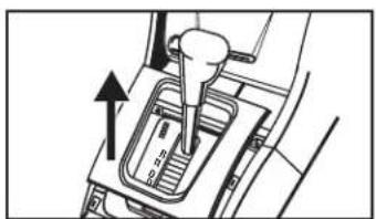
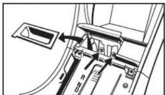
- Unclip and remove the shift lever trim ring. (Figure A)
- Unclip and remove the coin-tray/ashtray and then remove the (2) Phillips screws exposed. (Figure B)
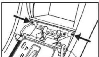
- Remove the (2) Phillips screws from the bottom of pocket, then unclip and remove. (Figure C)
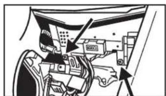
- Remove the (2) Phillips screws facing up, underneath the radio/climate control assembly. (Figure D)
- Push and hold the hazard button down. Carefully insert a small panel removal tool into the slot below the button, and then push down to release the center clip. (Figure E)
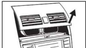
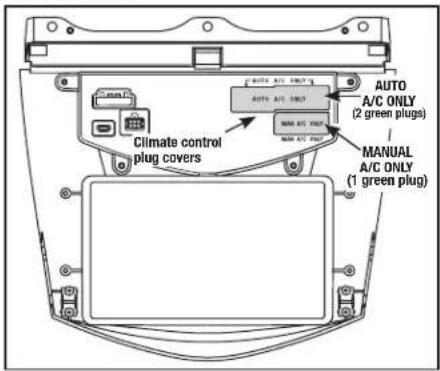
- Unclip and remove the A/C vent panel, and then remove the (3) Phillips screws exposed. (Figure F)
Note: You can use a hook tool to grasp the panel inside of the vent and pull toward the rear of the vehicle. Be careful not to scratch the panel.
- Unclip and remove the radio/climate control assembly.
Continue to Kit Preparation
natural_image
Mechanical component diagram showing a lever mechanism with an upward arrow (no text or symbols)(Figure A)
natural_image
Mechanical assembly diagram showing internal components with arrows indicating motion (no text or labels)(Figure D)
text_image
Technical diagram showing mechanical assembly with labeled components and directional arrows(Figure B)

natural_image
Line drawing of hands using a tool to adjust or install a component on a vehicle (no text or symbols visible)(Figure E)

text_image
0 P R(Figure C)
natural_image
Diagram of an air conditioner unit with airflow direction indicated by an arrow (no text or symbols)(Figure F)

99-7803G
Kit Preparation
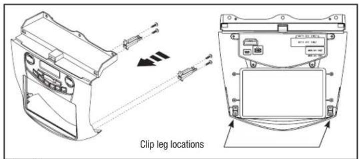
- Secure the (2) panel clip legs to the radio housing trim panel with the (4) #4 x 3/8" Phillips pan-head screws supplied, and then attach the panel clips. (Figure A)
- Attach the (2) speed clips provided to the bottom mounting legs of the radio brackets. (Figure B)
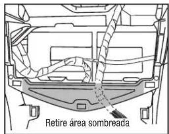
- Cut and remove the center section of the dash cavity (Figure C). Be sure to leave the outside clip slots intact. (Figure D)
Note: Some models may be slightly different.
Continue to Kit Assembly
text_image
Clip leg locations(Figure A)

natural_image
Pure technical line drawing of a mechanical bracket with a fastener attached (no text or symbols)(Figure B)

text_image
Remove shaded area(Figure C)

text_image
Cut close without cutting into clip slot(Figure D)

99-7803G
Kit Assembly
ISO DIN radio provision with pocket
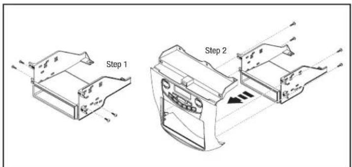
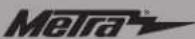
- Secure the pocket to the radio brackets with the (4) #8 x 3/8" Phillips truss-head screws provided. (Figure A, Step 1)
- Secure the bracket/pocket assembly to the radio trim panel with the (4) #8 x 3/8" Phillips truss-head screws provided. (Figure A, Step 2)
- Remove the metal DIN sleeve and trim ring from the aftermarket radio.
- Slide the radio into the assembly and then secure with the screws supplied with the radio. (Figure B)
Continue to Axxess Interface Installation
text_image
Step 1 Step 2(Figure A)

natural_image
Technical line drawing of a car airbag with directional arrows indicating motion (no text or symbols)(Figure B)
99-7803G
Kit Assembly
ISO DDIN radio provision
- Secure the radio brackets to the radio trim panel with the (4) #8 x 3/8" Phillips truss-head screws provided. (Figure A, Step 1)
- Slide the radio into the assembly and then secure with the screws supplied with the radio. (Figure A, Step 2)
Continue to Axxess Interface Installation
text_image
Step 1 Step 2(Figure A)

99-7803G
Axxess interface Installation
INTERFACE FEATURES
- Pre-wired ASWC-1 harness (ASWC-1 sold separately)
- Retains balance and fade
- Micro "B" USB updatable
INTERFACE COMPONENTS
- 7803 harness
TOOLS REQUIRED
- Wire cutter • Crimp tool • Solder gun • Tape
- Connectors (example: butt-connectors, bell caps, etc.)
Table of Contents
Connections to be made....7
Installing the interface 7
Changing the back-light color on the display ..... 8
CAUTION! All accessories, switches, climate controls panels, and especially air bag indicator lights must be connected before cycling the ignition. Also, do not remove the factory radio with the key in the on position, or while the vehicle is running.
Connections to be made Installing the interface
From the 7803 harness to the aftermarket radio:
- Connect the Black wire to the ground wire.
- Connect the Yellow wire to the battery wire.
- Connect the Red wire to the accessory wire.
- Connect the Blue wire to the power antenna wire.
- If the aftermarket radio has an illumination wire, connect the Orange wire to it.
- Connect the White wire to the left front positive speaker output.
- Connect the White/Black wire to the left front negative speaker output.
- Connect the Gray wire to the right front positive speaker output.
- Connect the Gray/Black wire to the right front negative speaker output.
- Connect the Green wire to the left rear positive speaker output.
- Connect the Green/Black wire to the left rear negative speaker output.
- Connect the Purple wire to the right rear positive speaker output.
- Connect the Purple/Black wire to the right rear negative speaker output.
- Tape off and disregard the following (3) wires with a red bullet connector, they will not be used in this application: White/Black, White/Red, Black.
12-pin pre-wired ASWC-1 harness:
- This harness is to be used along with the optional ASWC-1 (sold separately) to retain steering wheel audio controls. If the ASWC-1 is not being used, disregard this harness. If it will be used, please refer to the ASWC-1 instructions for radio connections and programming.
Note: Disregard the harness thomes with the ASWC-1.
With the key in the off position:
- Connect the 7803 harness into the 99-7803G, and then to the wiring harness in the vehicle.
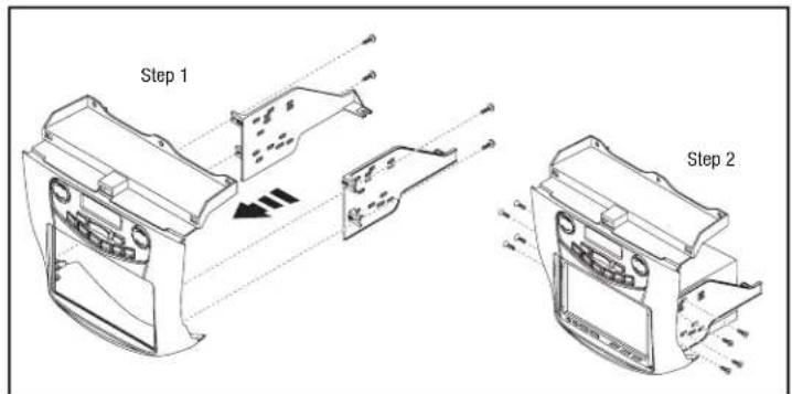
- Connect the factory climate control harness(es) into the 99-7803G kit.
Attention! Prior to turning the ignition on, verify that you have the harness connected into the correct climate control port in the kit. Connecting the harness into the incorrect port can permanently damage the kit. Refer to the picture on the following page.
- Locate the factory antenna connector in the dash and complete all necessary connections to the radio.
- Before using the kit it must be programmed.
Attention! If the interface loses power for any reason, the following steps will need to be performed again. Also, if installing an ASWC-1 connect it after you program and test the interface/radio, with the key in the off position.
a. Start the vehicle, and then hold the rear defrost button until the LCD display starts flashing.
b. Pay attention to the number / letter combinations during this learning sequence. This sequence will take roughly 1 minute. Writing down all of the numbers will help Tech Support if there is a problem.
c. After the display stops cycling through the different number / letter combinations, it will hold on its final designation. At this point it will be programmed.
d. Turn the vehicle off, and then start the vehicle again. Test all functions of the installation for proper operation, before reassembling the dash. The climate controls in the 99-7803G kit will function the same way that it did with the factory climate controls.
Note: Press and hold the "Dual" button for 5 seconds to switch the temp display between Fahrenheit and Celsius.
- Secure the completed assembly into the dash using the (2) #10 x 3/4" Phillips screws provided, and then reassemble the dash in reverse order of disassembly.


Changing the back-light color on the display
- Press and hold the mode button for 5-10 seconds. The display will start flashing slowly.
- Press and hold the left side temp up button to increase red.
- Press and hold the left side temp down button to decrease red.
- Press and hold the fan up button to increase green.
- Press and hold the fan down button to decrease green.
- Press and hold the right side temp up button to increase blue.
-
Press and hold the right side temp up button to decrease blue.
-
After 10 seconds of no activity the color chosen will be locked in.
text_image
Climate control plug covers AUTO A/C ONLY AUTO A/C ONLY AUTO A/C ONLY MAN A/C ONLY MAN A/C ONLY AUTO A/C ONLY (2 green plugs) MANUAL A/C ONLY (1 green plug)IMPORTANT
If you are having difficulties with the installation of this product, please call our Tech Support line at 1-800-253-TECH. Before doing so, look over the instructions a second time, and make sure the installation was performed exactly as the instructions are stated. Please have the vehicle apart and ready to perform troubleshooting steps before calling.

KNOWLEDGE IS POWER
Enhance your installation and fabrication skills by paralling in the most recognized and respected.
mobile electronics school in our industry.
Log onto www.installerinstitute.com or call
600-334-6182 for more information and take steps toward a better tomorrow.

Metra recommends MECP
certified technicians

U.S. PATENT # D756.348
Honda Accord 2003-2007 99-78036
CARACTERÍSTICAS DEL KIT
natural_image
Technical illustration of various screw fasteners and mounting brackets (no text or symbols)natural_image
Mechanical gear shift lever diagram showing motion direction (no text or labels)(Figura A)
natural_image
Mechanical assembly diagram showing internal components with arrows indicating movement (no text or labels)(Figura D)

text_image
R Ω(Figura B)

natural_image
Line drawing of hands using a tool to adjust or install a car interior panel (no text or symbols visible)(Figura E)
text_image
Technical diagram showing mechanical component with labeled parts and directional arrows indicating assembly or movement(Figura C)

natural_image
Diagram of a refrigerator with air conditioner unit and airflow arrow (no text or symbols)(Figura F)

99-7803G
Preparación del kit
natural_image
Pure technical line drawing of a mechanical bracket with a separate mounting bracket (no text or symbols)(Figura B)
natural_image
Technical line drawing of a car air intake manifold with control panel and fan (no text or symbols)(Figura B)

99-7803G
Ensamble del kit
Nota: Disregard the harness thomes with the ASWC-1.