99-6525HG - Car stereo AXESS - Free user manual and instructions
Find the device manual for free 99-6525HG AXESS in PDF.

User questions about 99-6525HG AXESS
0 question about this device. Answer the ones you know or ask your own.
Ask a new question about this device
Download the instructions for your Car stereo in PDF format for free! Find your manual 99-6525HG - AXESS and take your electronic device back in hand. On this page are published all the documents necessary for the use of your device. 99-6525HG by AXESS.
USER MANUAL 99-6525HG AXESS
natural_image
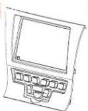
Interior view of a car dashboard with steering wheel, dashboard display, and control panel (no visible text or symbols)Chrysler 300 2011-2014
KIT FEATURES
• ISO DIN radio provision with pocket
- ISO DDIN radio provision
- Integrated buttons and included interface for climate functions
- Painted matte black (99-6525B) or high gloss black (99-6525HG)
Note: • Does not retain sound from Driver Convenience Group.
- Track and launch control features from SRT Package will be lost.
KIT COMPONENTS
• A) Radio trim panel with climate controls • B) Radio brackets • C) Lower support bracket • D) Pocket • E) Metal panel clips (2) • F) Plastic panel clips (2) • G) #8 x 3/8" Phillips pan-head screws (2) • H) #8 x 1/2" Phillips countersunk flat-head screws (2) • Climate extension cable (not shown)
- AXXESS interface and wiring harness (not shown)
A B

F


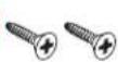
TABLE OF CONTENTS
Dash Disassembly 2
Kit Assembly
- ISO DIN radio provision with pocket......3
- ISO DDIN radio provision ....4
AXXESS interface installation....5-10
WIRING & ANTENNA CONNECTIONS
Wiring Harness: Included
Antenna Adapter: 40-EU55 (sold separately)
AXXESS steering wheel control interface (sold separately)
TOOLS REQUIRED
- Panel removal tool • Phillips screwdriver
• T-30 Torx driver
ATTENTION: With the key out of the ignition, disconnect the negative battery terminal before installing this product. Ensure that all installation connections, especially the air bag indicator light, must be secure before cycling the ignition to test this product.
NOTE: Refer also to the instructions included with the aftermarket radio.
DASH DISASSEMBLY
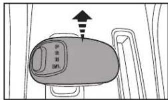
- Unsnap and remove the top half of the shift knob. (Figure A)
- Remove (1) T-30 Torx screw securing the knob and then remove the knob. (Figure B)
- Unsnap and remove the panel surrounding the shift knob. (Figure C)
text_image
伊豆逊 进入
natural_image
Technical line drawing of a mechanical component with an arrow pointing to a specific part (no text or symbols present)
natural_image
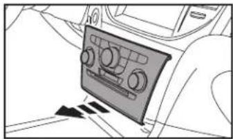
Interior view of a car air intake console with a tray and control panel (no text or symbols visible)(Figure C)
- Using the panel removal tool, carefully unclip, unplug and remove the radio/climate control panel. (Figure D) Note: The harness removed from this panel will connect to the climate extension cable.
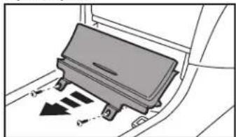
- Remove (2) Phillips screws securing the pocket below the climate control panel, and then unclip and remove the pocket. (Figure E)
- Remove the (4) Phillips screws securing the radio chassis, and then unplug and remove the chassis from the dash cavity. Note: The white round cable connected to the radio chassis will connect into the Axxess interface to drive the factory display screen.
Continue to Kit Assembly
natural_image
Interior view of a car showing the dashboard and air vent (no text or symbols visible)(Figure D)(Figure A)
natural_image
Diagram of a car seatbelt with directional arrows indicating movement (no text or symbols)(Figure E)(Figure B)
KIT ASSE MB LY
ISO DIN radio provision with pocket
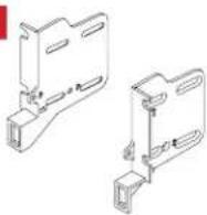
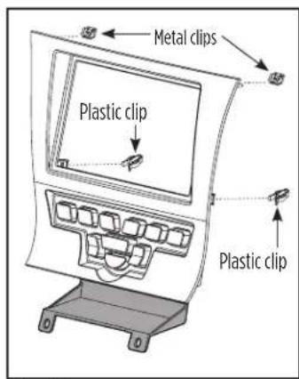
- Attach the metal clips provided with this kit to the top and the plastic clips provided to the bottom of the radio trim panel. (Figure A)
- Attach the lower support bracket to the radio trim panel with climate controls. (Figure A)
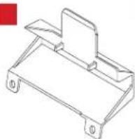
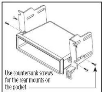
- Attach the radio brackets to the pocket using the (2) #8 x 3/8" Phillips pan-head screws provided with this kit towards the front of the pocket, and the (2) #8 x 1/2" Phillips flat-head screws provided towards the back. (Figure B)
Note: If the screws are not attached this way, the assembly will not slide into the dash.
text_image
Metal clips Plastic clip Plastic clip(Figure A)
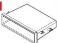
- Remove the metal "DIN" sleeve and trim ring from the aftermarket radio.
- Slide the radio into the pocket/bracket assembly, and then secure using the screws supplied with the radio. (Figure C)
Continue to Axxess Interface Installation
text_image
Use countersunk screws for the rear mounts on the pocket(Figure B)
natural_image
Technical line drawing of a mechanical device with labeled components (no text or symbols)(Figure C)
KIT ASSE MB LY
ISO DDIN radio provision
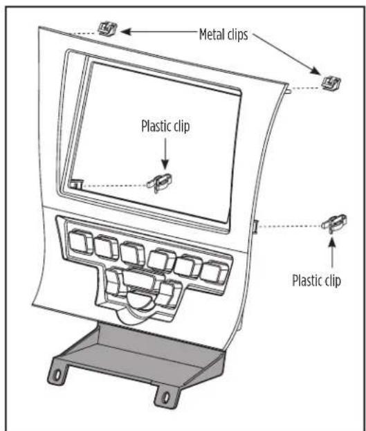
- Attach the metal clips provided with this kit to the top and the plastic clips provided to the bottom of the radio trim panel. (Figure A)
- Attach the lower support bracket to the radio trim panel with climate controls. (Figure A)
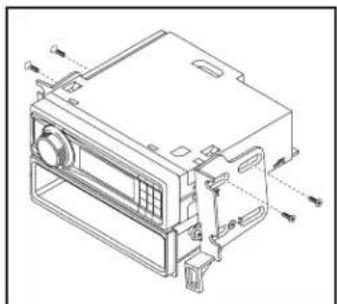
- Attach the radio brackets to the radio using the screws supplied with the radio. (Figure B)
Continue to Axxess Interface Installation
text_image
Metal clips Plastic clip Plastic clip(Figure A)
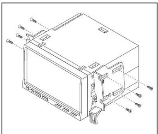
natural_image
Technical line drawing of an electronic device casing with mounting holes and internal components (no text or symbols)(Figure B)
AXXESS INTERFACE INSTALLATION
TABLE OF CONTENTS
Connections To Be Made 5-6
Installing The Interface 6
Final Assembly 6
Screen Operation....7-9
Updating The Interface 10
INTERFACE FEATURES
- Provides accessory power (12-volt 10-amp)
- Retains R.A.P. (retained accessory power)
• Used in amplified and non-amplified systems - Provides NAV outputs (parking brake, reverse, and speed sense)
- Prewired for an AXXESS steering wheel control interface
- High level speaker input
- Retains balance and fade
- Ability to add an aftermarket backup camera or additional video input
- Retains factory screen
- Micro "B" USB updatable
INTERFACE COMPONENTS
- Axxess Interface • 16-pin harness with stripped leads • 6525 harness with stripped leads
TOOLS REQUIRED
- Cutting tool • Crimping tool • Tape • Connectors (example: butt-connectors, bell caps, etc.)
CONNECTIONS TO BE MADE
From the 16-pin harness with stripped leads to the aftermarket radio, connect as indicated:
- Red wire to the accessory wire.
Note: If using an AXXESS steering wheel control interface (sold separately), there will be a Red wire there to connect as well. - Orange/White wire to the illumination wire if applicable.
• Blue/White wire to the amp turn-on wire.
The following (3) wires are for aftermarket multimedia/navigation radios that provide these wires (if not required, tape them off and disregard them).
• Light Green wire to the parking brake.
• Blue/Pink wire to the VSS or speed sense wire.
• Green/Purple wire to the reverse wire.
- Tape off and disregard the following (9) wires, they will not be used in this application: Brown, White, White/Black, Gray, Gray/Black, Purple, Purple/Black, Green, and Green/Black
Continued on the next page
CONNECTIONS TO BE MADE (CONT)
From the 6525 harness to the aftermarket radio, connect as indicated:
- Black wire to the ground wire.
- White wire to the left front (+) speaker output.
- White/Black wire to the left front (-) speaker output.
- Gray wire to the right front (+) speaker output.
- Gray/Black wire to the right front (-) speaker output.
- Green wire to the left rear (+) speaker output.
• Green/Black wire to the left rear (-) speaker output.
• Purple wire to the right rear (+) speaker output.
• Purple/Black wire to the right rear (-) speaker output.
- Yellow wire from both the 6525 harness and the loose yellow wire coming from the HVAC controller to the battery wire.
To the 18-pin harness:
Tape off and disregard the following (4) wires, they will not be used in this application:
Purple, Purple/Black, Green, Green/Black
- Disregard the Yellow RCA jack labeled (1), it will not be used in this application.
- Yellow RCA jack labeled (2) to either an aftermarket backup camera, or an AUX video input.
Note: This is optional if you desire to have the backup camera or AUX video image on the factory screen. If you prefer to have the image on the aftermarket radio instead, connect the backup camera or AUX video to the aftermarket radio.
INSTALLING THE INTERFACE
With the key in the off position:
- Connect the 16-pin harness with stripped leads into the interface.
Note: The potentiometer which is located on the 16-pin harness side of the interface is for future applications. - Connect the 6525 harness into the interface, and then into the vehicle.
- Connect the climate extension cable into the connector behind the radio trim panel with climate controls, and then into the vehicle.
Note: This harness must be connected for the climate controls to function. - Connect the white round cable removed from the radio chassis in dash disassembly, into the Axxess interface.
Note: If this is not connected, the factory display screen will not function.
Attention! For models with a 4.2-inch screen, please update the interface via the Axxess Updater available via axxessinterfaces.com. Select "4.2-inch screen" once prompted.
FINAL ASSEMBLY
- Locate the factory antenna connector in the dash, and complete all necessary connections to the radio. Metra recommends using the proper mating adapter from Metra.
Note: If using the AXXESS steering wheel control interface (sold separately), connect it after you program and test the 99-6525, with the key in the off position. - Initialize the kit by turning the ignition on until the radio comes on, then turn the ignition back off, then back on again.
Note: If the 99-6525 loses power for any reason, this step will need to be performed again. - Test the aftermarket radio and climate controls for proper operation.
- Mount the completed assembly into the dash using the 99-6525 radio trim panel with climate controls, and then reassemble the dash in the reverse order of disassembly to complete the installation.
text_image
Diagram of a car air conditioner front panel with labeled buttons and icons for function, status, and display.- Radio button – Show the current time
- Player button – Not used in this application
- Climate button – Takes you to the climate screen
- Setting button - Takes you to the setting screen
- More button – Shows the outside temperature and current time
- Screen Off – Turns the display off
FACTORY 4.3 INCH SCREEN VIDEO OPTIONS MENU
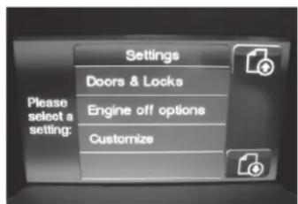
- Once in the setting screen, scroll down to the Customize button. Pressing the button will take you to the video option screen. (Figure A)
- Once in the customize menu, you can select to make the Video Input 2 either: (Figure B)
text_image
Please select a setting: Settings Doors & Locks Engine off options Customize(Figure A) (Figure C)
- Not Used
- Back-up (Backup Camera) is controlled by data and will only activate when you put the vehicle in reverse.
-
AUX input is controlled by data and will only work while the vehicle is in park. (Figure C)
-
After you have made your selection, tap the "Done" button located on the upper left hand corner of the screen to exit.
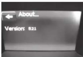
- The About button will display the current software of the kit, and also the VIN of the vehicle. (Figure D)

text_image
Done Video Input Line #2 BACK-UP AUX NOT USED Camera selection will turn on when in Reverse. Use the "PLAYER" button to cycle through the Climate and active Video screen(s) manually.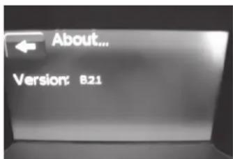
text_image
About... Version: B21
text_image
Customize Video Input #1 Video Input #2 About... Please select a setting:(Figure B) (Figure D)
text_image
84 MAX A/C AUTO FLO 84 OFF 84 OFF 1 2 3 4 5 6 7 SYNC- Enter the settings menu by tapping the gear icon in the upper left corner of the screen.

text_image
Settings Lights > Doors & Locks > Engine Off Options > Auto-On Comfort & Remote Start > Compass > Customize >- Once in the setting menu, scroll down and tap the Customize button to enter the customize menu.

text_image
Settings Customize Video Input 2 Not Used Play Aux About-
Once in the customize menu, you can select to make the Video Input 2 either:
-
Not Used
- Reverse (Backup Camera) is controlled by data and will only activate when you put the vehicle in reverse.
- AUX input is controlled by data and will only work while the vehicle is in park.
text_image
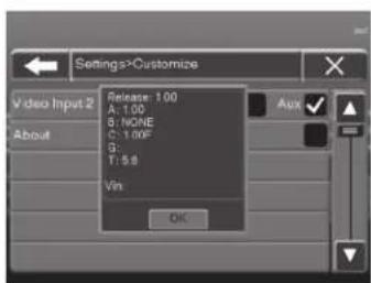
Settings>Customize Video Input 2 About Release: 1.00 A: 1.00 B: NONE C: 1.00F G: T: 9.8 Vin OK- Tapping the About button will display the current version number of the kit, and the VIN number of the vehicle. Tap the OK button to exit.
- After you have made your selection, tap either the X or Back (left arrow) button one time to return to the previous menu, or two times to return to the main menu.
UPDATING THE INTERFACE
- Download and install the Axxess Updater from axxessinterfaces.com.
- Connect the USB-MINI-CAB update cable (sold separately) between the interface and the computer. The cable will connect into the micro-B USB port inside the interface.
- From the Start Menu of the computer, click on "Axxess Updater", and then click "Update Firmware". The interface will begin to update at this point.
Note: Please note which firmware downloaded to the interface. This will help in troubleshooting, if need be.
Having difficulties? We're here to help.

ur Tech Support line at:
386-257-1187

mail at:
techsupport@metra-autosound.com
Tech Support Hours (Eastern Standard Time)
Monday - Friday: 9:00 AM - 7:00 PM
Saturday: 10:00 AM - 5:00 PM
Sunday: 10:00 AM - 4:00 PM

KNOWLEDGE IS POWER
Enhance your installation and fabrication skills by supplying in the most recognized and supported
mobile electronics school in our industry.
Log onto www.installennstitute.edu or call
306-672-5771 for more information and take steps toward a better tomorrow.

Metra recommends MECP certified technicians

natural_image
Interior view of a car dashboard with steering wheel, dashboard display, and control panel (no visible text or symbols)Chrysler 300 2011-2014
CARACTERÍSTICAS DEL KIT
natural_image
Technical line drawing of a mechanical component with an arrow pointing to a specific part (no text or symbols present)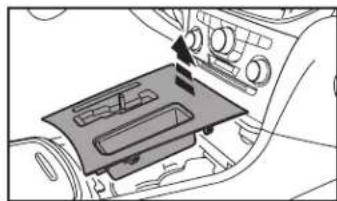
natural_image
Interior view of a car air intake console with a tray and control panel (no text or symbols visible)(Figura C)
natural_image
Interior view of a car showing the dashboard and air vent (no text or symbols visible)(Figura D)(Figura A)

natural_image
Diagram of a car seatbelt mechanism with directional arrows indicating movement (no text or symbols)(Figura E)(Figura B)
ENSAMBLE DEL KIT
natural_image
Technical line drawing of a mechanical device with labeled components (no text or symbols)(Figura C)
ENSAMBLE DEL KIT
natural_image
Technical line drawing of a device housing with mounting holes and internal components (no text or symbols)(Figura B)
text_image
Diagram of a car air conditioner front panel with labeled buttons and icons for function, status, and display.text_image
Please select a setting: Settings Doors & Locks Engine off options Customize(Figura A) (Figura C)
text_image
Done Video Input Line #2 BACK-UP AUX NOT USED Camera selection will turn on when in Reverse. Use the "PLAYER" button to cycle through the Climate and active Video presentation manually.
text_image
Customize Video Input #1 Video Input #2 About... Please select a setting:(Figura B) (Figura D)
text_image
About... Version: B21text_image
Settings>Customize Video Input 2 Release: 1.00 A: 1.00 B: NONE C: 1.00# D: 5.00 E: 5.00 F: 5.00 Vin: OKMóvil (Mobile Electronics
Certification Program, MECP).