5900 - Pump Waterstone - Free user manual and instructions
Find the device manual for free 5900 Waterstone in PDF.

User questions about 5900 Waterstone
0 question about this device. Answer the ones you know or ask your own.
Ask a new question about this device
Download the instructions for your Pump in PDF format for free! Find your manual 5900 - Waterstone and take your electronic device back in hand. On this page are published all the documents necessary for the use of your device. 5900 by Waterstone.
USER MANUAL 5900 Waterstone
CONTEMPORARY PLP PULLDOWN FAUCET INSTALLATION INSTRUCTIONS
Model #s:
5300, 5400, 5410, 5700, 5800, 5810,
5900, 5910, 5930, 5940

natural_image
Modern kitchen faucet with curved glass end, no visible text or symbols
BEFORE YOU BEGIN YOUR INSTALLATION:
1

Turn off water supply. Observe all local

plumbing codes.

natural_image
Black and white icon of a pipe with falling water, symbolizing water pollution or drainage (no text or symbols)Inspect plumbing for signs of damage. Replace as necessary.

text_image
Prohibition sign with a black water droplet symbol crossed out by a diagonal line, indicating no pollution or water release.DO NOT use petroleum based products on this faucet.
REQUIRED TOOLS:


Phillips ScrewdriverAdjustable Wrench
Channel Locks
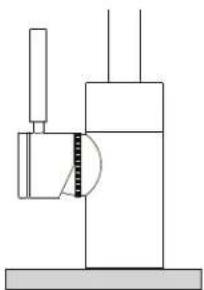
HANDLE POSITION
Waterstone faucets are designed to be installed in 3 different faucet positions. Choose to have the handle on left, front or right. Your faucet is factory configured for the most common positions - a front and right side installation. To reverse this and have the handle positioned on the left, connect the hose for cold water to the hot supply and the hose for hot water to the cold supply. This will maintain the relationship of pulling the handle for hot water or pushing for cold water.
natural_image
Pure mechanical diagram showing a lever and pivot mechanism without any text, numbers, or symbols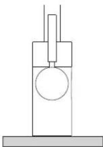
natural_image
Simple line drawing of a mechanical setup with a cylinder and a vertical rod (no text or symbols)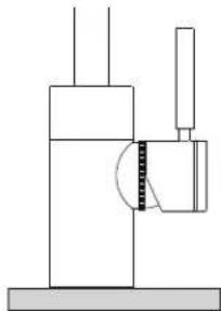
natural_image
Pure mechanical diagram showing a lever and shaft assembly without any text, numbers, or symbolsHANDLE ON LEFT HANDLE IN FRONT HANDLE ON RIGHT
PULLDOWN FAUCET INSTALLATION

text_image
1. C B ARemove the clamp nut (A) and washer (B) from the threaded shroud (C).
text_image
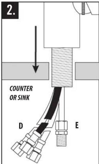
2. COUNTER OR SINK D EFit flexible hoses (D) and spray connection tube (E) through hole on counter or sink. (No plumbers putty is required. O-ring seals base).
natural_image
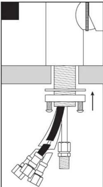
Mechanical assembly diagram showing a clamping mechanism with no visible text or symbolsSlide washer and thread the clamp nut onto threaded shroud. Tighten nut snug to underside of sink or counter.

text_image
Technical diagram showing mechanical assembly with labeled component 'F' and directional arrowTurn faucet to the desired handle position. Securely tighten clamp screws (F).
HOW TO ADJUST HANDLE POSITION AND HANDLE TENSION
natural_image
Mechanical diagram showing a rotating component with a circular end, labeled FIG.1 (no text or symbols on the diagram itself)natural_image
Pure mechanical diagram showing a rotating component with arrows indicating motion (no text or symbols)NEW ADJUSTED POSITION CLEARS BACKSPLASH
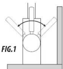
On some kitchen countertops, the handle may hit the backsplash when the faucet handle is positioned to the left or right (Fig. 1). Waterstone gives you the option of adjusting the handle 22.5 degrees to avoid hitting backsplash.
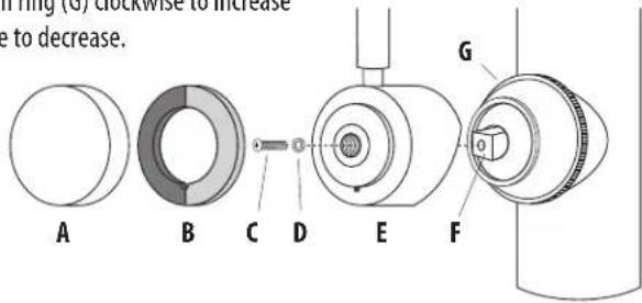
Unscrew and remove metal cap (A) and Hot and Cold Indicator Ring (B). Unscrew and remove holding screw (C) and washer (D). Hold handle (E) in a vertical position. Wiggle and pull straight off faucet. Rotate handle 22 degrees away from backsplash then slide handle back onto valve stem (F). Insert holding screw with washer and tighten. Slide Hot and Cold Indicator Ring onto handle and thread metal cap back into place. To adjust handle tension, turn ring (G) clockwise to increase or counterclockwise to decrease.
text_image
Ring (6) clockwise to increase to decrease. A B C D E F GCONNECTING SUPPLY HOSES
Before connecting supply hoses, flush supply stops to clear any debris. Place a bucket underneath stops and run water for 5 to 10 seconds. Turn water off. Carefully position hot and cold supplies so they will not interfere with other hoses. Connect supply hoses (A) to supply stops (B). DO NOT use teflon tape or plumbers putty. Turn water back on and check for leaks.
text_image
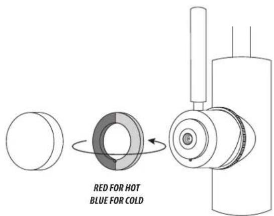
A BOPTIONAL HOT COLD INDICATOR RING
To reverse, or remove Hot and Cold Indicator Ring, unscrew the metal cap, remove ring and flip. Slide ring back onto handle and screw metal cap back on.
text_image
RED FOR HOT BLUE FOR COLDCONNECT THE PULLDOWN SPRAY HOSE

text_image
Connect spray hose (A) to spray connection hose tube (B). NOTE – make sure spray hose (A) and counter balance (C) are free to slide up and down and are not in conflict with any plumbing components or items under sink. A B CCLEANING DEBRIS SCREEN
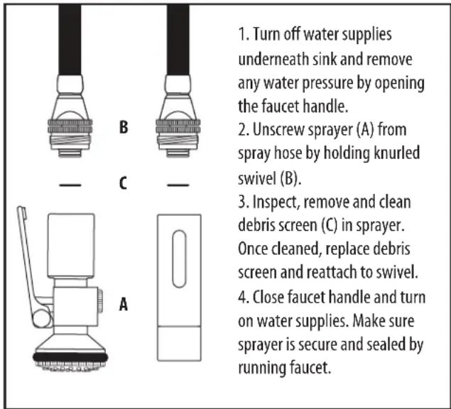
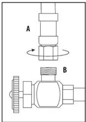
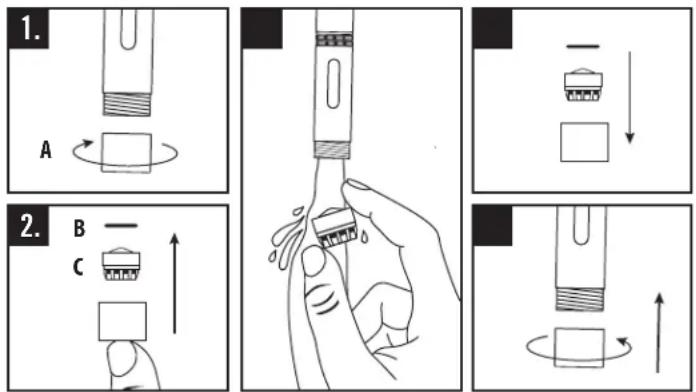
text_image
1. Turn off water supplies underneath sink and remove any water pressure by opening the faucet handle. 2. Unscrew sprayer (A) from spray hose by holding knurled swivel (B). 3. Inspect, remove and clean debris screen (C) in sprayer. Once cleaned, replace debris screen and reattach to swivel. 4. Close faucet handle and turn on water supplies. Make sure sprayer is secure and sealed by running faucet.CLEANING AERATOR - TOGGLE SPRAYER
text_image
1. A 2. B C- Gently unscrew and remove spout tip (A) by hand.
- Remove O-ring (B). To remove aerator (C), push with finger from bottom.
- Thoroughly rinse aerator with water until all debris is removed.
- Place aerator, then 0-ring back into spout tip.
- Gently screw spout tip, by hand, snuggly back onto spout.
CLEANING AERATOR - LEVER SPRAYER

text_image
1. A B — C D 4.- Gently unscrew and remove spray face (A) by hand.
- To remove O-ring (B), aerator (C) and spray face insert (D), push with finger from bottom.
- Thoroughly rinse aerator with water until all debris is removed.
- Place spray face insert back into spray face and spin until it clicks into place. Next, place aerator and 0-ring into spray face. Gently screw spray face, by hand, snuggly back onto sprayer.
INSTALL SOAP/LOTION DISPENSER (OPTIONAL)
text_image
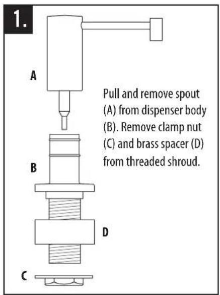
1. A B C D Pull and remove spout (A) from dispenser body (B). Remove clamp nut (C) and brass spacer (D) from threaded shroud.
text_image
2. 1-3/8" HOLE COUNTER OR SINK Fit dispenser body through 1-3/8" hole on counter or sink. (No plumbers putty is required). Slide brass spacer onto shroud. Screw clamp nut and tighten snug.
text_image
3. Fill plastic bottle with soap or lotion. Thread bottle (E) into bottom of dispenser shroud.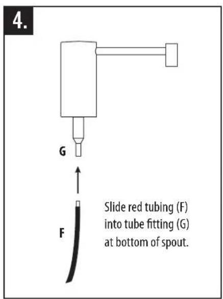
text_image
4. G F Slide red tubing (F) into tube fitting (G) at bottom of spout.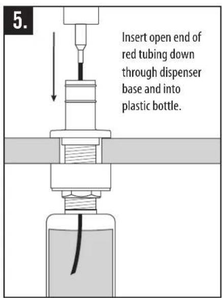
text_image
5. Insert open end of red tubing down through dispenser base and into plastic bottle.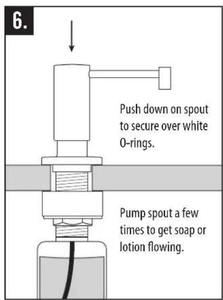
text_image
6. Push down on spout to secure over white O-rings. Pump spout a few times to get soap or lotion flowing.INSTALL AIR SWITCH (OPTIONAL)
text_image
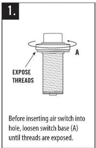
1. EXPOSE THREADS A Before inserting air switch into hole, loosen switch base (A) until threads are exposed.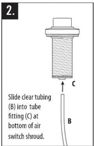
text_image
2. Slide clear tubing (B) into tube fitting (C) at bottom of air switch shroud. C B
text_image
3. 1-1/2" HOLE COUNTER OR SINK Fit air switch and tubing through 1-1/2" hole on counter or sink. (No plumbers putty is required. O-ring seals base).
text_image
Slide washer up then screw the clamp nut onto threaded shroud. Hand tighten nut to underside of sink or counter until snug.CONTINUED FROM PREVIOUS PAGE
text_image
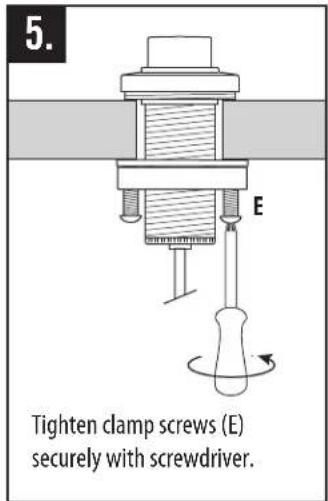
5. E Tighten clamp screws (E) securely with screwdriver.
text_image
6. Hand tighten switch base back down to cover threads.
text_image
7. Slide other end of tubing (F) into tube fitting at bottom of control box (G). G F
text_image
GARBAGE DISPOSAL Plug control box into undersink electrical outlet. Plug garbage disposal into either dual outlet.INSTALL SINGLE PORT AIR GAP (OPTIONAL)

text_image
1. Twist and pull air gap cover (A) off of upper cap nut (B). Unscrew and remove cap nut from piping (C).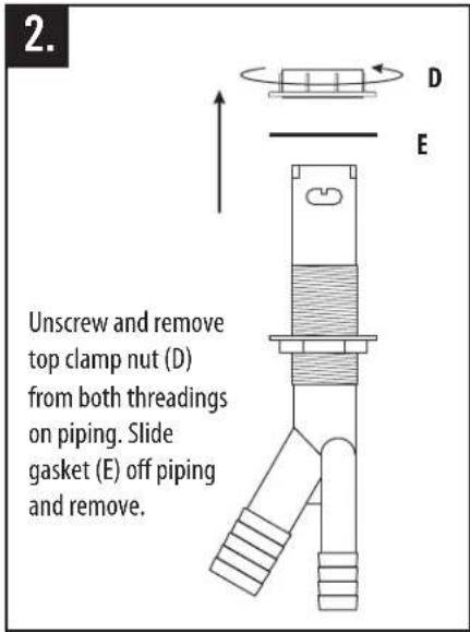
text_image
2. Unscrew and remove top clamp nut (D) from both threadings on piping. Slide gasket (E) off piping and remove.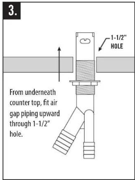
text_image
3. 1-1/2" HOLE From underneath counter top, fit air gap piping upward through 1-1/2" hole.
text_image
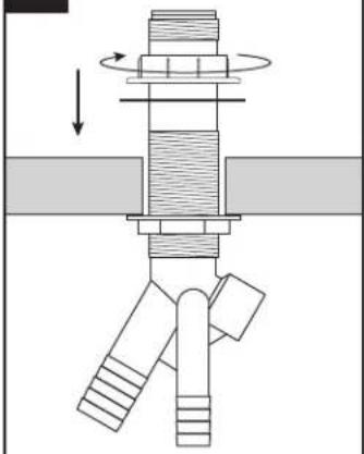
Slide gasket down and screw top clamp nut back onto piping. Adjust the two clamp nuts to fit countertop thickness. (No plumbers putty is required).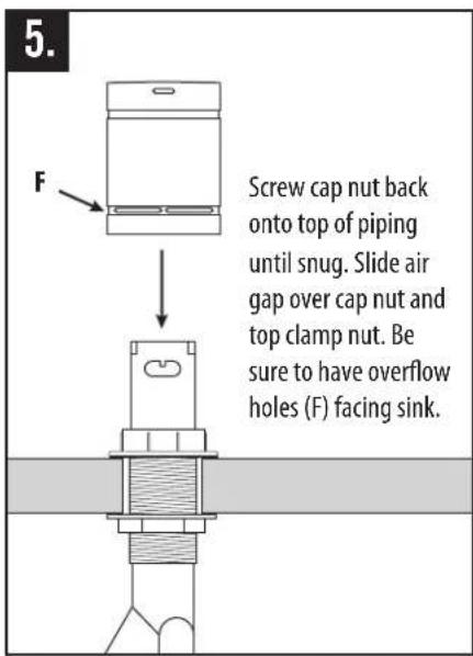
text_image
5. F Screw cap nut back onto top of piping until snug. Slide air gap over cap nut and top clamp nut. Be sure to have overflow holes (F) facing sink.
text_image
6. Slide small intake hose (G) over small connector. Slide larger drainage hose (H) over large connector. Tighten hose clamps. Turn on water supply and check for leaks. H GINSTALL DUAL PORT AIR GAP (OPTIONAL)

text_image
A B CPull air gap (A) off of upper cap nut (B). Unscrew and remove cap nut from piping (C).

text_image
Technical diagram showing a mechanical assembly with labeled components D and E, including a rotating component and a cross-sectional view.Unscrew and remove top clamp nut (D) from both threadings on piping. Slide gasket (E) off piping and remove.
text_image
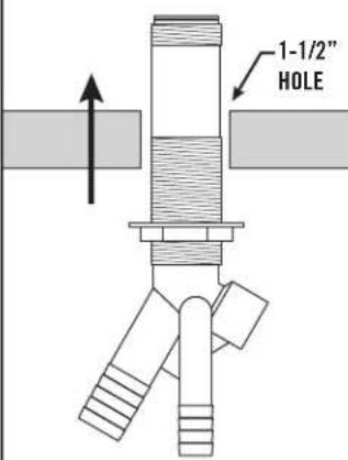
1-1/2" HOLEFrom underneath counter top, fit air gap piping upward through 1-1/2" hole.
The image is too blurry to recognize any text content.
natural_image
Mechanical assembly diagram showing a rotating shaft and connecting rod (no text or labels)Slide gasket down and screw top clamp nut back onto piping. Adjust the two clamp nuts to fit countertop thickness. (No plumbers putty is required).

text_image
FScrew cap nut back onto top of piping until snug. Slide air gap over cap nut and top clamp nut. Be sure to have overflow holes (F) facing sink.
text_image
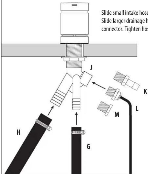
Slide small intake hose Slide larger drainage h connector. Tighten hos H G J K M LSlide small intake hose (G) over small connector. Slide larger drainage hose (H) over large connector. Tighten hose clamps.
Third intake hole (J) has 3 options. Use hose connector (K) for additional dishwasher, use filtration hose connector (L) for reverse osmosis unit, or use solid cap (M) to plug third hole.