CHLSC39TX - Dimmer Ltech - Free user manual and instructions
Find the device manual for free CHLSC39TX Ltech in PDF.

Pick your language and provide your email: we'll send you a specifically translated version.
User questions about CHLSC39TX Ltech
0 question about this device. Answer the ones you know or ask your own.
Ask a new question about this device
No questions yet. Be the first to ask one.
Download the instructions for your Dimmer in PDF format for free! Find your manual CHLSC39TX - Ltech and take your electronic device back in hand. On this page are published all the documents necessary for the use of your device. CHLSC39TX by Ltech.
USER MANUAL CHLSC39TX Ltech
text_image
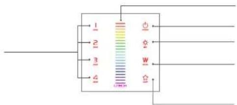
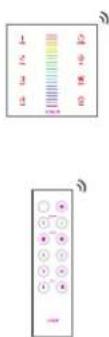
Digital thermometer display showing current reading, color scale, and O/O color gauge with Chinese labelsLTECH
L-BUS
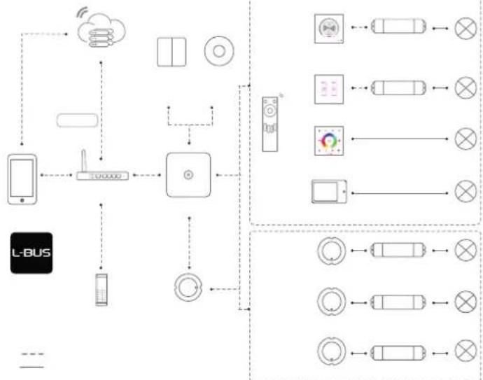
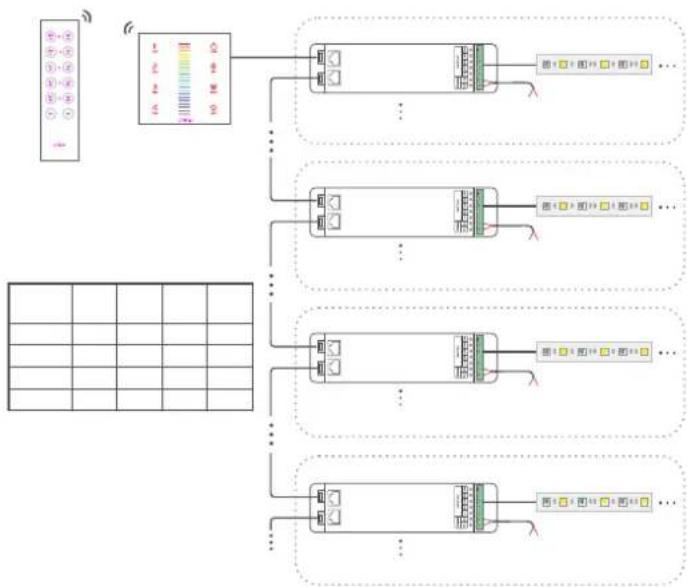
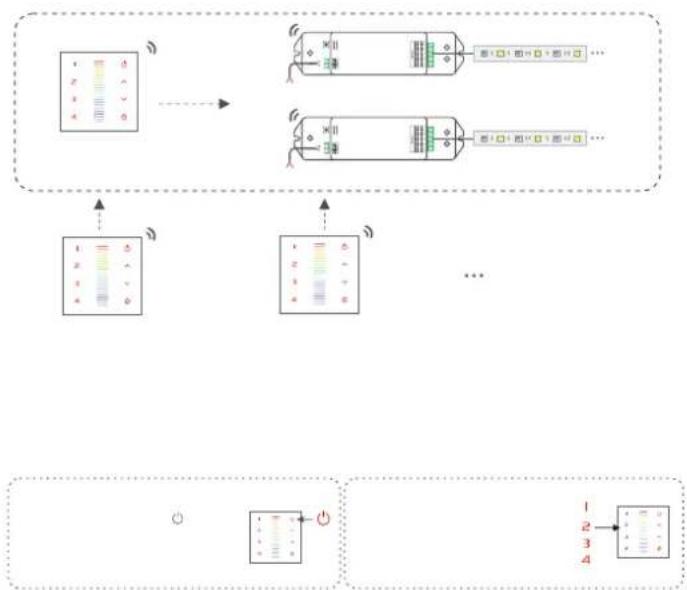
flowchart
graph TD
    A["L-BUS"] --> B["Smartphone"]
    B --> C["Router"]
    C --> D["Control Unit"]
    D --> E["Mobile Device"]
    E --> F["Wireless Cloud"]
    F --> G["Remote Control Unit"]
    G --> H["Display Module"]
    H --> I["Radio System"]
    I --> J["Switch"]
    J --> K["External Display"]
    K --> L["Display Module"]
    L --> M["Remote Control Unit"]
    M --> N["Switch"]
    N --> O["External Display"]
    O --> P["Display Module"]
    P --> Q["External Display"]
    Q --> R["Switch"]
    R --> S["External Display"]
    S --> T["Display Module"]
    T --> U["External Display"]
    U --> V["Switch"]
    V --> W["External Display"]
    W --> X["Display Module"]
    X --> Y["External Display"]
    Y --> Z["Switch"]
LTECH
FC CE RoHS ( ) ISO2001-2004
LTECH

text_image
Technical diagram showing a measurement setup with labeled components and color-coded scales for display or testing.LTECH
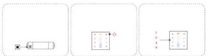
natural_image
Simple diagram of a rectangular container with four circular ports, no text or symbols present

natural_image
Pure electrical circuit lines without any symbolsLTECH

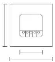
text_image
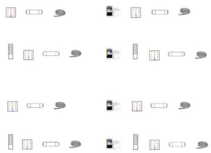
1 2 3 4
text_image
1 2 3 4 C O A V BLTECH

text_image
1 2 3 4 5 6 7 8 9 10 11 12 13 14LTECH
text_image
1 2 3 4 W W G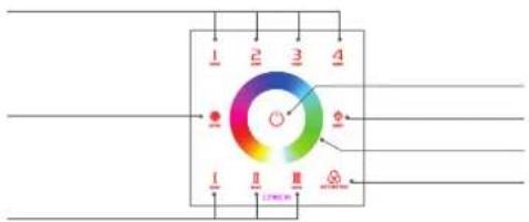
text_image
1 2 3 4 I II III Φ Φ Φ 1 2 3 4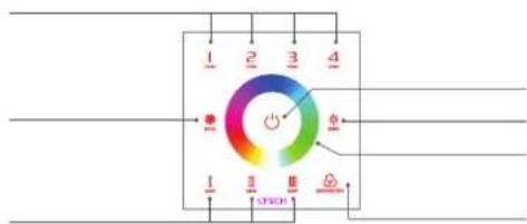
text_image
1 2 3 4 - - - - - - - - - - - - - - - - - - - - - - - - - - - - - - - - - - - - - - - - - - - - - - - - - - - - - - - - - - - - - - - - - -


LTECH
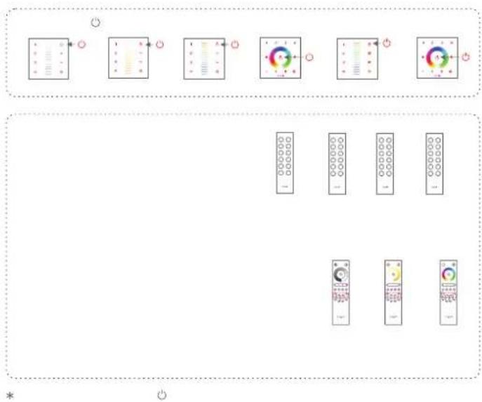
flowchart
graph TD
    A["Smart Device"] --> B["Cloud Service"]
    B --> C["Smart Device"]
    C --> D["Smart Device"]
    D --> E["Smart Device"]
    E --> F["Smart Device"]
    F --> G["Smart Device"]
    G --> H["Smart Device"]
    H --> I["Smart Device"]
    I --> J["Smart Device"]
    J --> K["Smart Device"]
    K --> L["Smart Device"]
    L --> M["Smart Device"]
    M --> N["Smart Device"]
    N --> O["Smart Device"]
    O --> P["Smart Device"]
    P --> Q["Smart Device"]
    Q --> R["Smart Device"]
    R --> S["Smart Device"]
    S --> T["Smart Device"]
    T --> U["Smart Device"]
    U --> V["Smart Device"]
    V --> W["Smart Device"]
    W --> X["Smart Device"]
    X --> Y["Smart Device"]
    Y --> Z["Smart Device"]
    Z --> AA["Smart Device"]
    AA --> AB["Smart Device"]
    AB --> AC["Smart Device"]
    AC --> AD["Smart Device"]
    AD --> AE["Smart Device"]
    AE --> AF["Smart Device"]
    AF --> AG["Smart Device"]
    AG --> AH["Smart Device"]
    AH --> AI["Smart Device"]
    AI --> AJ["Smart Device"]
LTECH
natural_image
Grid of 20 abstract icons including battery, car, camera, and road signs (no text or symbols)LTECH
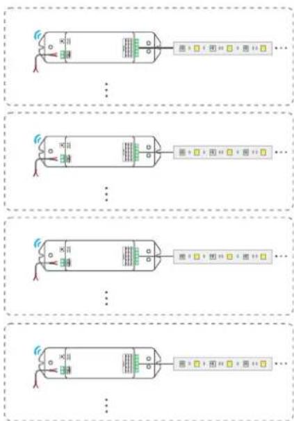
flowchart
graph TD
    A["Input Module"] --> B["Data Collection"]
    B --> C1["Component 1"]
    B --> C2["Component 2"]
    B --> C3["Component 3"]
    B --> C4["Component 4"]
    C1 --> D1["Output Module 1"]
    C2 --> D2["Output Module 2"]
    C3 --> D3["Output Module 3"]
    C4 --> D4["Output Module 4"]
LTECH
flowchart
graph TD
    A["Input Port 1"] --> B["Control Bus"]
    C["Input Port 2"] --> D["Control Bus"]
    E["Input Port 3"] --> F["Control Bus"]
    G["Input Port 4"] --> H["Control Bus"]
    I["Output Port 1"] --> J["Feedback Loop"]
    K["Output Port 2"] --> L["Feedback Loop"]
    M["Output Port 3"] --> N["Feedback Loop"]
    O["Output Port 4"] --> P["Feedback Loop"]
LTECH
flowchart
graph TD
    A["Input Channel 1"] --> B["Processing Unit"]
    C["Input Channel 2"] --> B
    D["Input Channel 3"] --> B
    E["Input Channel 4"] --> B
    B --> F["Output Signal 1"]
    B --> G["Output Signal 2"]
    B --> H["Output Signal 3"]
    B --> I["Output Signal 4"]
LTECH
flowchart
graph TD
    A["Control Panel 1"] --> B["Function Block 1"]
    B --> C["Function Panel 2"]
    C --> D["Function Panel 3"]
    D --> E["Function Panel 4"]
    E --> F["Function Panel 5"]
    F --> G["Remote Control Panel 1"]
    G --> H["Remote Control Panel 2"]
    H --> I["Remote Control Panel 3"]
    I --> J["Remote Control Panel 4"]
LTECH

flowchart
graph LR
    A["Switch"] --> B["Car"]
    B --> C["Capacitor"]
    C --> D["Load"]
    D --> E["Capacitor"]
    E --> F["Load"]
    style A fill:#f9f,stroke:#333
    style B fill:#ccf,stroke:#333
    style C fill:#cfc,stroke:#333
    style D fill:#fcc,stroke:#333
    style E fill:#cff,stroke:#333
    style F fill:#ffc,stroke:#333
flowchart
graph LR
    A["Device 1"] --> B["Control Panel 1"]
    B --> C["Control Panel 2"]
    C --> D["Control Panel 3"]
LTECH
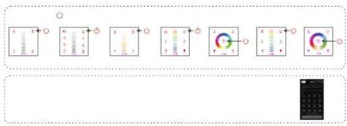
text_image
Diagram showing a sequence of analog meters with labeled readings and indicators, likely for measurement or calibration.
flowchart
graph LR
    A["Step 1: Bar"] --> B["Step 2: Column"]
    B --> C["Step 3: Column"]
    C --> D["Step 4: Plus Sign"]
    D --> E["Step 5: Column"]
    E --> F["Step 6: Column"]