CHLSC30TX - Dimmer Ltech - Free user manual and instructions
Find the device manual for free CHLSC30TX Ltech in PDF.

Pick your language and provide your email: we'll send you a specifically translated version.
| Product Type | LED Dimmer |
| Brand | Ltech |
| Model | CHLSC30TX |
| Input Voltage | 12-24V DC |
| Max Output Current | 3A |
| Max Load Power | 72W (at 24V) |
| Dimming Method | PWM (Pulse Width Modulation) |
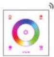
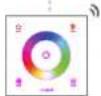
| Control Interface | Rotary knob with push ON/OFF |
| Compatible Loads | Constant voltage LED strip, LED modules |
| Dimensions (L x W x H) | 85 x 45 x 20 mm |
| Weight | 100 g |
| Operating Temperature | -20°C to +50°C |
| Housing Material | ABS plastic, flame retardant |
| Installation | In-line or junction box mounted |
| Protection Rating | IP20 (indoor use) |
| Certifications | CE, RoHS |
| Warranty | 2 years |
| Maintenance | Wipe with dry cloth; no liquid cleaners |
| Repairability | Non-repairable, replace unit if faulty |
Frequently Asked Questions - CHLSC30TX Ltech
How do I install the Ltech CHLSC30TX dimmer?
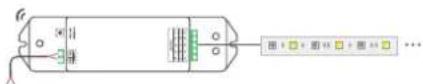
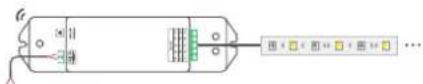
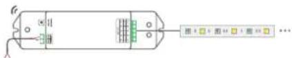
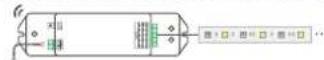
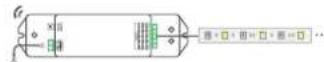
Connect the DC power supply to the input terminals (V+ and V-), then connect the LED load to the output terminals. Ensure the total load does not exceed 72W. Use a suitable junction box for safety.
Can I use this dimmer with any LED strip?
This dimmer is designed for constant voltage LED strips (12V or 24V). It is not compatible with constant current LEDs or mains voltage bulbs.
What is the minimum load required?
The minimum load is approximately 1W (at 12V) to ensure smooth dimming. Below this, the dimmer may not function correctly.
Does the dimmer emit noise?
The dimmer uses PWM at a frequency above audible range (typically >1kHz), so it is silent during operation.
How do I adjust the brightness?
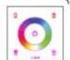
Turn the rotary knob clockwise to increase brightness, counterclockwise to decrease. Press the knob to switch ON/OFF.
Is the dimmer suitable for outdoor use?
No, the IP20 rating means it is only for indoor, dry locations. Keep away from moisture.
What should I do if the dimmer gets hot?
Ensure proper ventilation and that the load does not exceed the rated 72W. If overheating persists, reduce load or check connections.
Can I use multiple dimmers in parallel?
No, multiple dimmers should not be connected in parallel to control the same load. Use one dimmer per circuit.
How do I clean the dimmer?
Disconnect power, then wipe the casing with a soft, dry cloth. Do not use water or solvents.
What is the warranty period?
Ltech offers a 2-year warranty against manufacturing defects. Keep your purchase receipt.
User questions about CHLSC30TX Ltech
0 question about this device. Answer the ones you know or ask your own.
Ask a new question about this device
No questions yet. Be the first to ask one.
Download the instructions for your Dimmer in PDF format for free! Find your manual CHLSC30TX - Ltech and take your electronic device back in hand. On this page are published all the documents necessary for the use of your device. CHLSC30TX by Ltech.
USER MANUAL CHLSC30TX Ltech
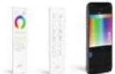
Q F
series series
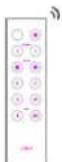
remote remote
LTECH
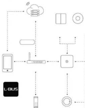
L-BUS
flowchart
graph TD
    A["L-BUS"] --> B["Mobile Device"]
    B --> C["Wireless Interface"]
    C --> D["Cloud"]
    D --> E["Smart Devices"]
    E --> F["Smart Phone"]
    F --> G["Remote Computer"]
    G --> H["Remote Display"]
    H --> I["Remote Radio"]
    I --> J["Remote Audio"]
    J --> K["Remote Display"]
    K --> L["Remote Radio"]
    L --> M["Remote Audio"]
    M --> N["Remote Display"]
    N --> O["Remote Radio"]
    O --> P["Remote Audio"]
    P --> Q["Remote Display"]
    Q --> R["Remote Radio"]
    R --> S["Remote Audio"]
    S --> T["Remote Display"]
    T --> U["Remote Radio"]
    U --> V["Remote Audio"]
    V --> W["Remote Display"]
    W --> X["Remote Radio"]
    X --> Y["Remote Audio"]
    Y --> Z["Remote Display"]
flowchart
graph LR
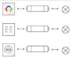
A["Input Block 1"] --> B["Cell"]
C["Input Block 2"] --> D["Cell"]
E["Input Block 3"] --> F["Cell"]
B --> G["Output"]
D --> H["Output"]
F --> I["Output"]
[Non-Text]
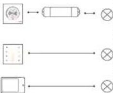
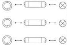
flowchart
graph TD
    A["Circle icon"] --> B["Rectangle"]
    B --> C["⊗"]
    D["Rectangle"] --> E["⊗"]
    E --> F["⊗"]
LTECH
LTECH
L-BUS
Advance Mode


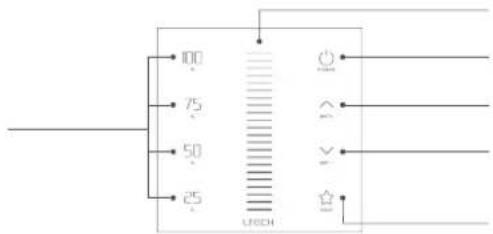
text_image
00 75 50 25 UBECHLTECH

natural_image
Technical line drawings of three mechanical components with dimension lines (no text or symbols)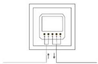
natural_image
Pure electrical circuit lines without any symbolsLTECH

text_image
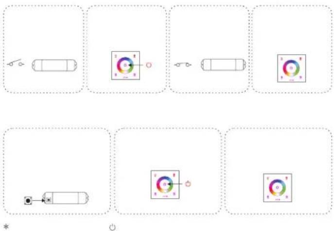
Diagram showing installation steps of a wall-mounted device with color-coded indicators and a screwdriver, including labeled components.LTECH

flowchart
graph TD
    A["Smart Phone"] --> B["Cloud"]
    A --> C["Wireless Device"]
    A --> D["Smart Lock"]
    B --> E["Smart Phone"]
    C --> F["Smart Phone"]
    D --> G["Smart Lock"]
    E --> H["Smart Phone"]
    F --> I["Smart Phone"]
    G --> J["Smart Lock"]
    H --> K["Cloud"]
    I --> L["Wireless Device"]
    J --> M["Smart Lock"]
    K --> N["Smart Phone"]
    L --> O["Smart Phone"]
    M --> P["Smart Lock"]
    N --> Q["Smart Phone"]
    O --> R["Smart Phone"]
LTECH
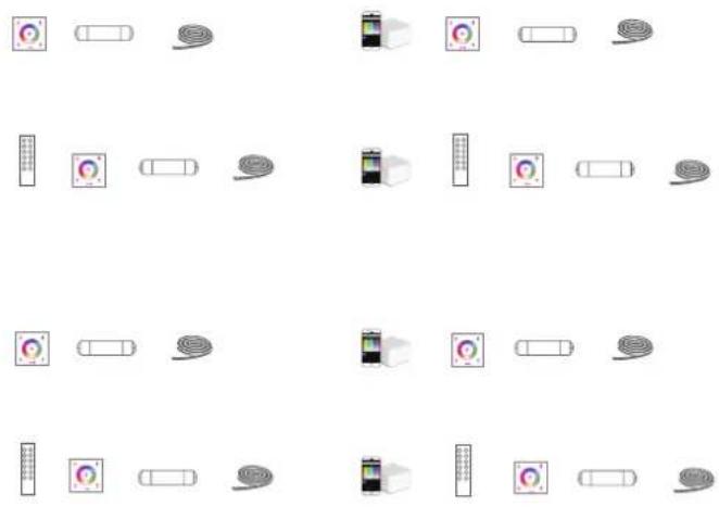
natural_image
Grid of 20 icons representing various devices and devices, arranged in two rows with no text or symbols.LTECH

flowchart
graph TD
    A["Control Panel"] --> B["Module 1"]
    A --> C["Module 2"]
    A --> D["Module 3"]
    A --> E["Module 4"]
    B --> F["Color Indicator"]
    C --> G["Color Indicator"]
    D --> H["Color Indicator"]
    E --> I["Color Indicator"]
    F --> J["..."]
    G --> K["..."]
    H --> L["..."]
    I --> M["..."]
    style A fill:#f9f,stroke:#333
    style B fill:#ccf,stroke:#333
    style C fill:#ccf,stroke:#333
    style D fill:#ccf,stroke:#333
    style E fill:#ccf,stroke:#333
LTECH

LTECH


LTECH
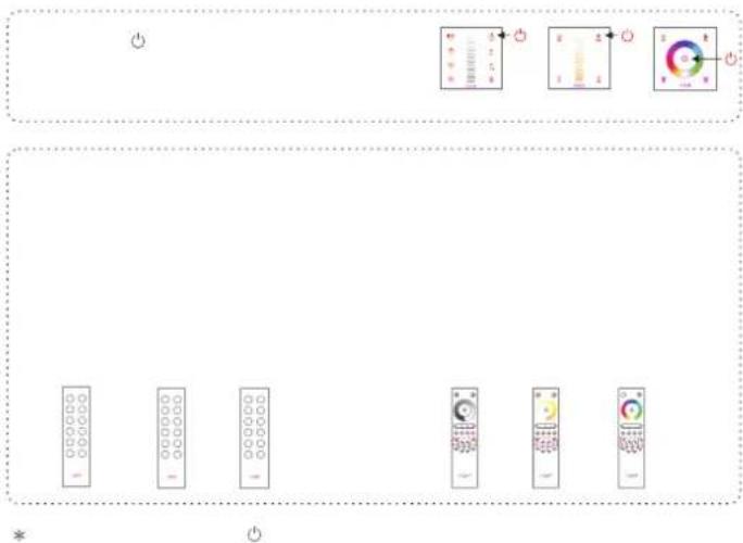
text_image
Diagram showing a row of remote control buttons with icons and labels, likely for a home control or navigation system.LTECH
flowchart
graph TD
    A["Top Left: Vehicle with switch"] --> B["Top Right: Battery with indicator light"]
    B --> C["Bottom Left: Battery with switch"]
    C --> D["Bottom Right: Indicator light with indicator light"]
    style A fill:#f9f,stroke:#333
    style B fill:#ccf,stroke:#333
    style C fill:#cfc,stroke:#333
    style D fill:#fcc,stroke:#333
LTECH

text_image
Diagram showing measurement scales and a control panel with labeled indicators and pointer positionsLTECH
• • • • • •
*