CHLSC50 - Dimmer Ltech - Free user manual and instructions
Find the device manual for free CHLSC50 Ltech in PDF.

| Type of Product | Dimmer |
| Brand | Ltech |
| Model | CHLSC50 |
| Input Voltage | 100-240V AC, 50/60Hz |
| Output Voltage | Same as input (non-phase cut) |
| Maximum Load | 150W (LED) / 250W (incandescent) |
| Dimming Type | Leading edge / trailing edge (selectable) |
| Compatible Loads | LED, incandescent, halogen, dimmable CFL |
| Minimum Load | 5W (LED) / 10W (incandescent) |
| Dimensions (L x W x H) | 85 x 45 x 25 mm |
| Weight | 100 g |
| Mounting | Wall box (DIN rail optional) |
| Connection Type | Screw terminals (2.5 mm² max) |
| Protection Class | IP20 (indoor use only) |
| Operating Temperature | -20°C to +40°C |
| Standby Power Consumption | <0.5W |
| Certifications | CE, RoHS |
| Warranty | 2 years |
| Cleaning Instructions | Wipe with dry cloth, no liquids |
| Spare Parts / Repairability | Not user-serviceable; consult electrician |
Frequently Asked Questions - CHLSC50 Ltech
User questions about CHLSC50 Ltech
0 question about this device. Answer the ones you know or ask your own.
Ask a new question about this device
Download the instructions for your Dimmer in PDF format for free! Find your manual CHLSC50 - Ltech and take your electronic device back in hand. On this page are published all the documents necessary for the use of your device. CHLSC50 by Ltech.
USER MANUAL CHLSC50 Ltech
text_image
E1 DIMMING E1S DIMMING E2 ICT E3 RGBI E3S RGBIMa ualn
www.ltech-led.com
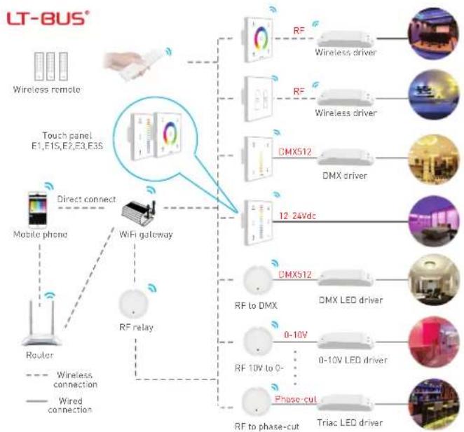
Product features
• 2 in 1 function: RF wireless control and PWM power output.
• Power output, lamps can be connected directly, easy and convenient.
- Touch keys with chord and LED indicator.
- Adapts capacitive touch control technology on the full color circle makes LED dimming selection more user-friendly.
- Touch panel can be controlled by remote directly or smart phone if add a gateway.
Technical specs
| Model | E1 | E1S | E2 | E3 | E3S |
| Control type | Dimming Dimning | CT | RGB RGB | ||
| Input voltage | 12-24Vdc | ||||
| Wireless frequency | RF 2.4GHz | ||||
| Current load | 4A×2CH Max. 8A | Max. 4A | 4A×3CH Max. 12A | ||
| Output power | 10~48W..96WI×2CH Max. 192W | 0~48W..96W | 10~48W..96WI×3CH Max. 288W | ||
| Protection | Short circuit / Over current protection, recover automatically. | ||||
| Working temp. | -20°C~55°C | ||||
| Dimensions | L86×W86×H36(mm) | ||||
| Package size | L113×W112×H50(mm) | ||||
| Weight[G.W.] | 225g | ||||


2
LTECH
flowchart
graph TD
    A["Wireless remote"] --> B["Touch panel E1,E1S,E2,E3,E3S"]
    B --> C["RF to DMX"]
    B --> D["DMX LED driver"]
    B --> E["Phase-cut"]
    B --> F["Triac LED driver"]
    C --> G["RF to DMX"]
    D --> H["0-10V"]
    E --> I["0-10V LED driver"]
    F --> J["RF to phase-cut"]
    B --> K["RF relay"]
    K --> L["Mobile phone"]
    L --> M["Router"]
    M --> N["Direct connect"]
    N --> O["WiFi gateway"]
    O --> P["Wireless connection"]
    style A fill:#f9f,stroke:#333
    style B fill:#ccf,stroke:#333
    style C fill:#cfc,stroke:#333
    style D fill:#fcc,stroke:#333
    style E fill:#cff,stroke:#333
    style F fill:#ffc,stroke:#333
    style G fill:#fcf,stroke:#333
    style H fill:#fcf,stroke:#333
    style I fill:#fcf,stroke:#333
    style J fill:#cff,stroke:#333
    style K fill:#ffc,stroke:#333
    style L fill:#cfc,stroke:#333
    style M fill:#fcc,stroke:#333
    style N fill:#cfc,stroke:#333
1
LTECH
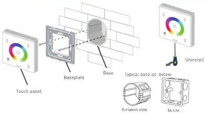
Installation instruction
text_image
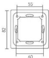
Touch panel Baseplate Base Typical base as below: European style 86 size UninstallProduct size
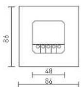
Unit: mm

3
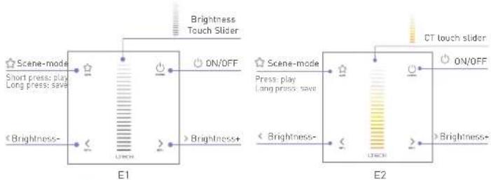
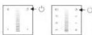
Key functions
LTECH
flowchart
graph LR
    subgraph E1
        A["Scene-mode"] --> B["Short press: play, Long press: save"]
        C["Brightness+"] --> D["➢ Brightness+"]
        B --> E["E1"]
        D --> E
        E --> F["ON/OFF"]
        G["CT touch slider"] --> H["On/OFF"]
    end
    subgraph E2
        I["Scene-mode"] --> J["Press: play, Long press: save"]
        K["Brightness+"] --> L["➢ Brightness+"]
        J --> M["E1"]
        L --> M
        M --> N["ON/OFF"]
        O["CT touch slider"] --> P["On/OFF"]
    end
* When blue status light of ⏻ key is on, long press ⏻ to turn on/off buzzer. When white status light of ⏻ key is on, long press ⏻ to match code.

flowchart
graph LR
    A["Brightness"] --> B["ON/OFF"]
    C["Shortcut Keys"] --> D["Brightness+"]
    E["Brightness-"] --> F["Scene-mode"]
    G["Short press play long press gate"] --> H["OFF"]
    I["Brightness Touch Slider"] --> J["OFF"]
    K["E1S"] --> L["0"]
    M["0"] --> N["0"]
    O["5"] --> P["5"]
    Q["10"] --> R["10"]
* When status light of ⏻ key is on, long press ⏻ to turn on/off buzzer. When status light of ⏻ key is off, long press ⏻ to match code.
LTECH
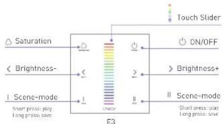
flowchart
graph TD
    A["Saturation"] --> B["< Brightness-"]
    C["< Scene-mode"] --> D["I Scene-mode"]
    B --> E["E3"]
    D --> E
    E --> F["Touch Slider"]
    F --> G["ON/OFF"]
    G --> H["> Brightness+"]
    H --> I["I Scene-mode"]
    I --> J["Short press: play Long press: save"]
* When blue status light of ○ key is on, long press ○ to turn on/off buzzer.
When while status light of ○ key is on, long press ○ to match code.
E3 panel's 2 scene-mode keys are corresponding with WiFi-106 gateway APP's 1 & 2 scene-mode key, the scenes can be changed by APP or panel.

text_image
Brightness- Speed- ON/OFF Mode E3S Brightness+ Speed+ Touch Color Circle Scene-mode Short press: play Long press: save* When blue status light of ○ key is on, long press ○ to turn on/off buzzer. When white status light of ○ key is on, long press ○ to match code.
Mode
- Static Red
- Static Green
- Static Blue
- Static Yellow
- Static Purple
- Static Cyan
- Static White
- RGB Jumping
- 7 Colors Jumping
- RGB Color Smooth
- Full-color Smooth
5
Match code sequence
LTECH

flowchart
graph TD
    A["Wi-Fi router"] --> B["Gateway"]
    C["Remote"] --> D["E series touch panel"]
    D --> E["Lamps"]
    style A fill:#f9f,stroke:#333
    style B fill:#ccf,stroke:#333
    style C fill:#cfc,stroke:#333
    style D fill:#fcc,stroke:#333
    style E fill:#cff,stroke:#333
Match Code Sequence
- Configure gateway touch panel, which enables the smart phone to control lamps via .gateway
- Configure remote with touch panel, which enables remote to control lamps.
* PS: No WiFi router needed when gateway work with phones directly.
Application composition

text_image
1. + Lamps Lamps 2. + Remote Remote 3. + WiFi master controller 4. + WiFi master controller + + Lamps LampsRF wireless wiring
Single Zone Control
LTECH
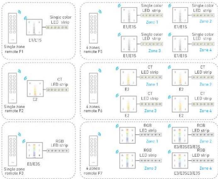
flowchart
graph TD
subgraph SingleZoneRemoteF1
A["Single color LED strip"] --> B["E1/E15"]
B --> C["Single zone remote F1"]
end
subgraph SingleZoneRemoteF2
D["CT LED strip"] --> E["E2"]
E --> F["Single zone remote F2"]
end
subgraph SingleZoneRemoteF3
G["RGB LED strip"] --> H["E3/E3S"]
H --> I["Single zone remote F3"]
end
subgraph SingleZoneRemoteF4
J["CT LED strip"] --> K["E2"]
K --> L["Single zone remote F4"]
end
subgraph SingleZoneRemoteF5
M["Single color LED strip"] --> N["E1/E15"]
N --> O["Single zone remote F5"]
end
subgraph SingleZoneRemoteF6
P["CT LED strip"] --> Q["E2"]
Q --> R["Single zone remote F6"]
end
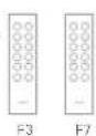
subgraph SingleZoneRemoteF7
S["RGB LED strip"] --> T["E3/E3SE3/E3S"]
T --> U["Single zone remote F7"]
end
* Touch panels can be sync controlled by multi remotes, please refer to the manual of remote's usage.
7
Terminals
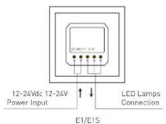
text_image
12-24Vdc 12-24V Power Input LED Lamps Connection E1/E15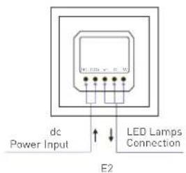
text_image
dc Power Input LED Lamps Connection E2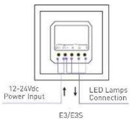
text_image
12-24Vdc Power Input LED Lamps Connection E3/E3S8
Match code between touch panel & remote
LTECH
E1/E1S touch panel match up with F1/F5 remote.
- Long press ⏻ on touch panel until indicator lights flicker.
- Press any key on F1 remote (or the matching zone key on F5), the indicator light stop flicking, match successfully.

E2 touch panel match up with F2/F6 remote.
- Long press ⏻ on touch panel until indicator lights flicker.

- Press any key on F2 remote (or the matching zone key on F6), the indicator light stop flicking, match successfully.
E3/E3S touch panel match up with F3/F7 remote.
- Long press ⏻ on touch panel until indicator lights flicker.

- Press any key on F3 remote (or the matching zone key on F7), the indicator light stop flicking, match successfully.
10
Wiring diagram
LTECH
E.g 1: Connect with 12V Strip. Max 48W/CH(12V)

text_image
E1/E1S E2 E3/E3S LED Strip Power supply 12VdcE.g 2: Connect with 24V Strip. Max 96W/CH(24V)

text_image
E1/E1S E2 E3/E3S LED Strip Power supply 24VdcMatch code between touch panel & gateway
LTECH
E1/E1S touch panel match up with gateway.
- Long press ⚙ on touch panel until indicator lights flicker.
- Click the corresponding DIM zone on mobile phone, then touch the color screen match successfully.

E2 touch panel match up with gateway.
- Long press ⏻ on touch panel until indicator lights flicker.

- Click the corresponding CT zone on mobile phone, then touch the color screen match successfully.

E3/E3S touch panel match up with gateway.
- Long press ○ on touch panel until indicator lights flicker.

- Click the corresponding RGB zone on mobile phone, then touch the color screen match successfully.

Clear code

Press the bottom two keys on touch panel simultaneously for 5 seconds, the indicator light flicker several times clear code successfully.
* Please match/clear code when panel status light of On/Off is white ||or EX1S is off.
www.ltech-led.com
Update Time: 2018.08.18 A1
11