GMV-NDX48P/A-T - Air-conditioner GREE - Free user manual and instructions
Find the device manual for free GMV-NDX48P/A-T GREE in PDF.

User questions about GMV-NDX48P/A-T GREE
0 question about this device. Answer the ones you know or ask your own.
Ask a new question about this device
Download the instructions for your Air-conditioner in PDF format for free! Find your manual GMV-NDX48P/A-T - GREE and take your electronic device back in hand. On this page are published all the documents necessary for the use of your device. GMV-NDX48P/A-T by GREE.
USER MANUAL GMV-NDX48P/A-T GREE
Original Instructions
Commercial Air Conditioners
Multi Variable Air Conditioners Fresh Air Series Indoor Unit
Models:
GMV-NDX42P/A-T(U)
GMV-NDX48P/A-T(U)
GMV-NDX54P/A-T(U)
GMV-NDX72P/A-T(U)
GMV-NDX96P/A-T(U)
Thank you for choosing commercial air conditioners. Please read this Owner's Manual carefully before operation and retain it for future reference.
If you have lost the Owner's Manual, please contact the local agent or visit www.gree.com or send an email to global@gree.com.cn for the electronic version.
GREE ELECTRIC APPLIANCES, INC. OF ZHUHAI
Preface
For correct installation and operation, please read all instructions carefully. Before reading the instructions, please be aware of the following items:
| This is the safety alert symbol. It is used to alert you to potential personal injury hazards. Obey all safety messages that follow this symbol to avoid possible injury or death. | |
| WARNING | This mark indicates procedures which, if improperly performed, might lead to the death or serious injury of the user. |
| CAUTION | This mark indicates procedures which, if improperly performed, might possibly result in personal harm to the user, or damage to property. |
| NOTICE | NOTICE is used to address practices not related to personal injury. |
| ⚠WARNING |
| Instructions for installation and use of this product are provided by the manufacturer. |
| (1) Installation must be performed in accordance with the requirements of NEC and CEC by authorized personnel only. |
| (2) For safety operation, please strictly follow the instructions in this manual. |
| (3) During operation, the gross rated capacity of working IDU should be within the gross rated capacity of ODU. Otherwise, IDU's cooling/heating performance will be reduced. |
| (4) This manual must be in the hands of direct operators or maintenance men. |
| (5) In case of malfunction and operation failure, please examine the following items and contact our authorized service centers as soon as possible.● Nameplate (model, cooling capacity, product code, ex-factory date).● Malfunction status (detail description of conditions before and after malfunction occurs). |
| (6) All units have been strictly tested and proved to be qualified before ex-factory. To avoid unit damage or even operation failure which may be caused by improper disassembly, please do not disassemble units by yourself. If disassembly is needed, please contact our authorized serve centers for help. |
| (7) All graphics and information in this manual are only for reference. Manufacturer reserves the right for changes in terms of sales or production at any time and without prior notice. |
| (8) If the supply cord is damaged, it must be replaced by the manufacturer, its service agent or similarly qualified persons in order to avoid a hazard. |
This appliance can be used by children aged from 8 years and above and persons with reduced physical, sensory or mental capabilities or lack of experience and knowledge if they have been given supervision or instruction concerning use of the appliance in a safe way and understand the hazards involved. Children shall not play with the appliance. Cleaning and user maintenance shall not be made by children without supervision.
DISPOSAL: Do not dispose this product as unsorted municipal waste. Collection of such waste separately for special treatment is necessary.
| Exception Clauses |
| Manufacturer will bear no responsibilities when personal injury or property loss is caused by the following reasons: |
| (1) Damage the product due to improper use or misuse of the product; |
| (2) Alter, change, maintain or use the product with other equipment without abiding by the instruction manual of manufacturer; |
| (3) After verification, the defect of product is directly caused by corrosive gas; |
| (4) After verification, defects are due to improper operation during transportation of product; |
| (5) Operate, repair, maintain the unit without abiding by instruction manual or related regulations; |
| (6) After verification, the problem or dispute is caused by the quality specification or performance of parts and components that produced by other manufacturers; |
| (7) The damage is caused by natural calamities, bad using environment or force majeure. |
Contents
1 Safety Precautions.... 1
2 Product Introduction.... 2
2.1 Unit Introduction....2
2.2 Rated Working Condition ....3
2.3 Working Temperature Range....3
3 Preparations for Installation .... 3
3.1 Standard Fittings .... 3
3.2 Location for Installation ....4
3.3 Requirements for Communication Line 5
3.4 Wiring Requirements 6
4 Installation Instructions.... 8
4.1 Installation of Indoor Unit....8
4.2 Pipe Connection....11
4.3 Installation and Test of Drain Pipe....11
4.4 Installation of Air Duct 13
4.5 Installation of Wired Controller....15
5 Wiring Work ....16
5.1 Connection of Wire and Patch Board Terminal 16
5.2 Power Cord Connection....17
5.3 Connection of Communication Line of IDU and ODU 17
5.4 Connect Communication Wire of Wired Controller 18
5.5 Illuminate for Connection of Wired Controller and Indoor Units Network .... 19
6 Routine Maintenance ....20
6.1 Cleaning of Filter....20
6.2 Maintenance before the Seasonal Use ....20
6.3 Maintenance after the Seasonal Use....21
7 Table of Error Codes for Indoor Unit ......21
8 Troubleshooting....22
1 Safety Precautions
| ▲WARNING |
| (1) This product can't be installed at corrosive, inflammable or explosive environment or the place with special requirements, such as kitchen. Otherwise, it will affect the normal operation or shorten the service life of the unit, or even cause fire hazard or serious injury. As for above special places, please adopt special air conditioner with anti-corrosive or anti-explosion function . |
| (2) Follow this instruction to complete the installation work. Please carefully read this manual before unit startup and service. |
| (3) Wire size of power cord should be large enough. The damaged power cord and connection wire should be replaced by exclusive cable. |
| (4) After connecting the power cord, please fix the electric box cover properly in order to avoid accident. |
| (5) Never fail to comply with the nitrogen charge requirements. Charge nitrogen when welding pipes. |
| (6) Never short-circiut or cancel the pressure switch to prevent unit damage. |
| (7) Please firstly connect the wired controller before energization, otherwise wired controller cannot be used. |
| (8) Before using the unit, please check if the piping and wiring are correct to avoid water leakage, refrigerant leakage, electric shock, or fire etc.. |
| (9) Do not insert fingers or objects into air outlet/inlet grille. |
| (10) Open the door and window and keep good ventilation in the room to avoid oxygen deficit when the gas/oil supplied heating equipment is used. |
| (11) Never start up or shut off the air conditioner by means of directly plug or unplug the power cord. |
| (12) Turn off the unit after it runs at least five minutes; otherwise it will influence oil return of the compressor. |
| (13) Do not allow children operate this unit. |
| (14) Do not operate this unit with wet hands. |
| (15) Turn off the unit or cut off the power supply before cleaning the unit, otherwise electric shock or injury may happen. |
| (16) Never spray or flush water towards unit, otherwise malfunction or electric shock may happen. |
| (17) Do not expose the unit to the moist or corrosive circumstances. |
| (18) Under cooling mode, please don't set the room temperature too low and keep the temperature difference between indoor and outdoor unit within 5 °C(41 °F). |
| (19) User is not allowed to repair the unit. Fault service may cause electric shock or fire accidents. Please contact Gree appointed service center for help. |
| (20) Before installation, please check if the power supply is in accordance with the requirements specified on the nameplate. And also take care of the power safety. |
| (21) Installation should be conducted by dealer or qualified personnel. Please do not attempt to install the unit by yourself. Improper handling may result in water leakage, electric shock or fire disaster etc.. |
| (22) Be sure to use the exclusive accessory and part to prevent the water leakage, electric shock and fire accidents. |
| (23) Make sure the unit can be earthed properly and soundly after plugging into the socket so as to avoid electric shock. Please do not connect the ground wire to gas pipe, water pipe, lightning rod or telephone line. |
| (24) Electrify the unit 8 hours before operation. Please switch on for 8 hours before operation. Do not cut off the power when 24 hours short-time halting (to protect the compressor). |
| (25) If refrigerant leakage happens during installation, please ventilate immediately. Poisonous gas will emerge if the refrigerant gas meets fire. |
| (26) Volatile liquid, such as diluent or gas will damage the unit appearance. Only use soft cloth with a little neutral detergent to clean the outer casing of unit. |
| (27) If anything abnormal happens (such as burning smell), please power off the unit and cut off the main power supply, and then immediately contact Gree appointed service center. If abnormality keeps going, the unit might be damaged and lead to electric shock or fire. |
GREE will not assume responsibility of personal injury or equipment damage caused by improper installation and commission, unnecessary service and incapable of following the rules and instructions listed in this manual.
2 Product Introduction
2.1 Unit Introduction
VRF fresh air series indoor unit is a kind of air processing unit that inhales the fresh air from outdoor side and then processes it to provide for the user in the room. According to the different selected air volume, there are two kinds of connection method for the VRF fresh air series indoor unit:
(1) If the selected air volume ≤1471 CFM, connect with normal indoor units by blow method, or connect with the fixed outdoor unit as shown in (2).
| Model of Indoor Unit | Model of Outdoor Unit |
| GMV-NDX42P/A-T(U) | Connecting condition with GMV-**WM/B-F(U) series modular outdoor unit:The total capacity of connected fresh air series indoor units and conventional VRF indoor units must be within 50%~100% of the capacity of outdoor unit, among which, the total capacity of connected fresh air indoor units cannot exceed 30% of the capacity of outdoor unit. |
| GMV-NDX48P/A-T(U) | |
| GMV-NDX54P/A-T(U) | |
| GMV-NDX72P/A-T(U) | |
| GMV-NDX96P/A-T(U) |
NOTICE! When fresh air series indoor units and conventional VRF indoor units will be connected, please follow the capacity requirement strictly. The total capacity of connected fresh air indoor units cannot exceed 30% of the capacity of outdoor unit, while the total capacity of indoor units shall be within 50%\~100% of the capacity of outdoor unit. Otherwise, the comfortableness will be affected or even the unit will be damaged.

text_image
Conventional VRF indoor unitsVRF fresh air series indoor units
Connection diagram of fresh air series indoor units and conventional VRF indoor units
(2) If the selected air volume >1471 CFM, it can only connect the fixed outdoor unit as below:
| Model of Indoor Unit | Model of Outdoor Unit |
| GMV-NDX54P/A-T(U) | GMV-72WM/B-F(U) |
| GMV-NDX72P/A-T(U) | |
| GMV-NDX96P/A-T(U) |
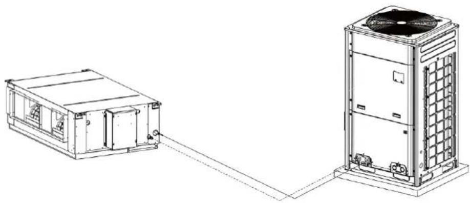
natural_image
Technical line drawing of a modular air conditioning unit connected to a high-voltage rack unit (no text or symbols present)2.2 Rated Working Condition
| Indoor Side Condition | Outdoor Side Condition | |||
| Dry Bulb Temp | Wet Bulb Temp | Dry Bulb Temp | Wet Bulb Temp | |
| Rated Cooling | 35°C(95°F) | 28°C(82°F) | 35°C(95°F) | 28°C(82°F) |
| Rated Heating | 7°C(45°F) | 6°C(43°F) | 7°C(45°F) | 6°C(43°F) |
2.3 Working Temperature Range
| Outdoor Ambient Dry Bulb | |
| Working Temperature Range | -7°C~45°C (19°F~113°F) |
NOTICE! The ex-factory set temperature is 18^ C ( 64^ F) in cooling mode and 22^ C ( 72^ F) in heating mode. If the user needs to change the temperature setting, please contact after-sales service personnel.
3 Preparations for Installation
NOTICE! Product graphics are only for reference. Please refer to actual products. Unspecified measure unit is mm (in.).
3.1 Standard Fittings
Please use the supplied standard fittings listed below as instructed.
| No. | Name | Graphics | Quantity | Function | ||
| 1 | Wired Controller | 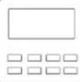 | 1PC | To control the indoor unit. | ||
| 2 | Union Nut Sub-assy |  | 1 Set | To be used for connecting the refrigerant pipe. | ||
| 3 | Corrugated pipe | 1 PC | GMV-NDX42~48P/A-T(U) | |||
| 4 | M10 Nut (Nut with Washer M10X8) | 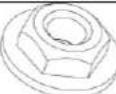 | 4 PC | To be used together with the hanger bolt for installing the unit. | ||
| 5 | M10 Nut (M10X8.4) | 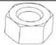 | 8 PC | To be used together with the hanger bolt for installing the unit. | ||
| No. | Name | Graphics | Quantity | Function | |
| 6 | M10 Washer(Spring Washer M10X2.6) | 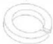 | 4 PC | To be used together with the hanger bolt for installing the unit. | |
| 7 | M10 Washer(M10XΦ30X 2.5) | 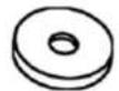 | 4 PC | To be used together with the hanger bolt for installing the unit. | |
| 8 | Insulation | 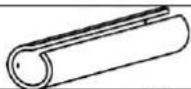 | 1 PC | To insulate the gas pipe. | |
| 9 | Insulation |  | 1 PC | To insulate the liquid pipe. | |
| 10 | Fastener | 8 PC | To fasten the sponge. | ||
| 11* | Hanger |  | 4 PC | To fix the indoor unit. | |
| 12* | M8 Nut (M8X6.8) |  | 8 PC | To fix the hook on the cabinet of the unit. | |
| 13* | M8 Washer(Spring Washer M8X2.1) |  | 8 PC | To fix the hook on the cabinet of the unit. | |
| 14* | M8 Washer(M8XΦ16X1.5) |  | 8 PC | To fix the hook on the cabinet of the unit. | |
| 15 | Sponge of Drain Pipe |  | 2 PC | Wrap the joint of drain pipe. | |
NOTICE!
① No.11*\~14* is only suitable to GMV-NDX54\~96P/A-T(U).
② The fittings list above is subject to change without notice, please refer to the packing list provided with indoor unit.
3.2 Location for Installation
(1) Appliances are not accessible to the general public.
(2) The top holder must be strong enough to support unit's weight.
(3) Drain pipe can drain water out easily.
(4) There is no obstacle at inlet or outlet. Please ensure good air circulation.
(5) In order to make sure the space for maintenance, please install the indoor unit according to the dimension described below.
(6) Keep the unit away from heat source, inflammable gas or smoke.
(7) This is a concealed ceiling type unit.
(8) This series indoor unit can be allowed to supply air for only one room.
(9) Indoor unit, outdoor unit, power cord and electric wire should stay at least 1m (3-1/4ft.) from the TV set and radio. Otherwise, these electric appliances may have image interference and noise (Even if the distance is 1m (3-1/4ft.), when there is strong electric wave, noise may still occur).
Unit: mm (in.)
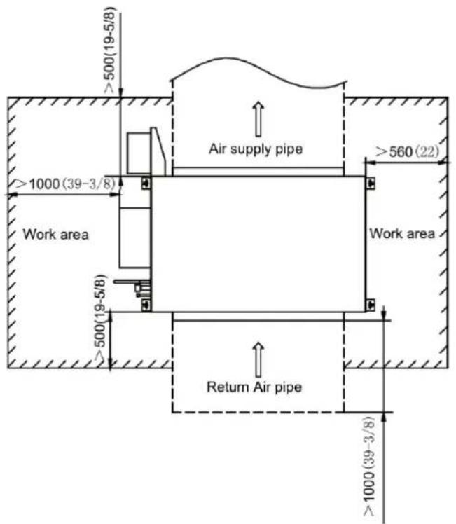
text_image
>500(19-5/8) Air supply pipe >560(22) >1000(39-3/8) Work area >500(19-5/8) Return Air pipe >1000(39-3/8)
text_image
>500(19-5/8) Ceiling >50(2) Air supply pipe Return Air pipe >2500(98-1/2)| ⚠WARNING |
| (1) Install the unit at a place where is adequate to withstand the weight of the unit and make sure the unit would not shake or fall off. |
| (2) Never expose the unit under direct sunshine and rainfall. Install the unit at a place where is against dust, typhoon and earthquake. |
| (3) Try to keep the unit away from combustible, inflammable and corrosive gas or exhaust gas. |
| (4) Leave some space for heat exchanging and servicing so as to guarantee unit normal operation. |
| (5) Keep the indoor and outdoor units close to each other as much as possible so as to decrease the pipe length and bends. |
| (6) Never allow children to approach to the unit and take measures to prevent children touching the unit. |
3.3 Requirements for Communication Line
NOTICE! If the unit is installed in the place with strong electromagnetic interference, shielded wire must be applied on the communication wire between indoor unit and wired controller. Twisted pair line with shielding function must be applied on the communication wire between indoor unit and indoor unit (outdoor unit).
3.3.1 Select communication line for indoor unit and wired controller

flowchart
graph TD
    A["Indoor unit 1"] -->|L1| B["Indoor unit 2"]
    B -->|L2| C["Indoor unit 3"]
    C -->|L(n-1)| D["Indoor unit n"]
    E["Sub-master controller"] --> F["L02"]
    G["Master controller"] --> H["L01"]
    I["L=L01+L02+L1+L2+L(n-1)(n≤16)"] --> J["End"]
Fig 3.3.1
| Material type | Total length of communication line between IDU unit and wired controller L m(ft.) | Wire size | Remarks |
| Light/Ordinary polyvinyl chloride sheathed cord. | L≤250(820-1/5) | 2× AWG18~2× AWG16 | 1. Total length of communication line can't exceed 250m (820-1/5feet).2. The cord shall be Circular cord (the cores shall be twisted together).3. If unit is installed in places with intense magnetic field or strong interference, it is necessary to use shielded wire. |
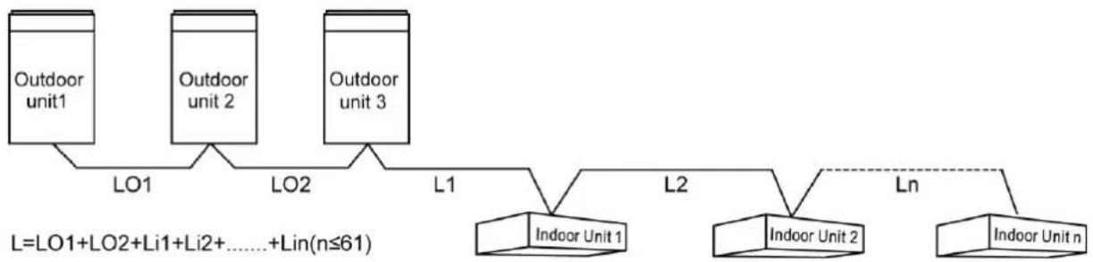
3.3.2 Select communication line for indoor unit and indoor unit (outdoor unit)
flowchart
graph TD
    A["Outdoor unit1"] --> B["LO1"]
    C["Outdoor unit 2"] --> D["LO2"]
    E["Outdoor unit 3"] --> F["L1"]
    B --> G["L2"]
    D --> G
    F --> H["L2"]
    G --> I["L2"]
    H --> J["L2"]
    I --> K["L2"]
    style A fill:#f9f,stroke:#333
    style C fill:#f9f,stroke:#333
    style E fill:#f9f,stroke:#333
    style B fill:#ccf,stroke:#333
    style D fill:#ccf,stroke:#333
    style F fill:#ccf,stroke:#333
    style G fill:#cfc,stroke:#333
    style H fill:#cfc,stroke:#333
    style I fill:#cfc,stroke:#333
    style J fill:#cfc,stroke:#333
    style K fill:#cfc,stroke:#333
Fig 3.3.2
| Material Type | Total Length of Communication Cable between IDU Unit and IDU (ODU) Unit L m(ft) | Wire size | Remarks |
| Light/Ordinary polyvinyl chloride sheathed cord. | L≤1000(3280-5/6) | ≥2×AWG18 | 1. If the wire diameter is enlarged to 2 × AWG16, the total communication length can reach 1500m (4921-1/4ft.).2. The cord shall be Circular cord (the cores shall be twisted together).3. If unit is installed in places with intense magnetic field or strong interference, it is necessary to use shielded wire. |
3.4 Wiring Requirements
Power Cord Size and Air Switch Capacity
| Model | Power Supply | Minimum Circuit Ampacity (A) | Maximum Overcurrent Protection (A) |
| GMV-NDX42P/A-T(U) | 208/230V 1Ph 60Hz | 1.7 | 15 |
| GMV-NDX48P/A-T(U) | 208/230V 1Ph 60Hz | 1.7 | 15 |
| GMV-NDX54P/A-T(U) | 208/230V 1Ph 60Hz | 1.7 | 15 |
| GMV-NDX72P/A-T(U) | 208/230V 1Ph 60Hz | 6.3 | 15 |
| GMV-NDX96P/A-T(U) | 208/230V 1Ph 60Hz | 6.3 | 15 |
WARNING
(1) Specification of circuit breaker and power cord is selected on the basis of unit's maximum power (max. current).
| ⚠WARNING |
| (2) Specification of power cord is based on the working condition where ambient temperature is 40 °C (104 °F) and multi-core cable with copper conductor(working temperature is 90 °C (194 °F), e.g. power cable with YJV cross-linked copper, insulated PE and PVC sheath) is lying on the surface of slot. If working condition is different, please adjust the specification according to national standard. |
| (3) Copper-core cable must be used. |
| (4) The above sectional area is suitable for a maximum distance of 15m (49-1/5ft.). If it's over 15m (49-1/5ft.), sectional area must be expanded to prevent overload current from burning the wire or causing fire hazard. |
| (5) Specification of circuit breaker is based on the working condition where the ambient temperature of circuit breaker is 40 °C (104 °F). If working condition is different, please adjust the specification according to national standard. |
| (6) The air switch should include magnetic trip function and thermal trip function so that system can be protected from short circuit and overload. |
| (7) An all-pole disconnection switch having a contact separation of at least 3mm (1/8in.) in all poles should be connected in fixed wiring. |
NOTICE!
① Use copper wire only as unit's power cord. Operating temperature should be within its rated value.
② If the power cord is more than 15 m (49-1/4 ft.) long, please increase properly the sectional area of power cord to avoid overload, which may cause accident.
③ Above selection requirements: Power cord size is based on BV single-core wire (2\~4pc) at 40^ C ( 104^ F) ambient temperature when laying across plastic pipe. Air switch is D type and used at 40^ C ( 104^ F). If actual installation condition varies, please lower the capacity appropriately according to the specifications of power cord and air switch provided by manufacturer.
④ Install cut-off device near the unit. The minimum distance between each stage of cut-off device should be 3 mm (1/8 in.) (The same for both indoor unit and outdoor unit).
4 Installation Instructions
4.1 Installation of Indoor Unit
4.1.1 Outline Dimension and Installation Spots
Equip with a service port after hanging the unit. For the convenience of maintenance, the service port should be on one side of the electric box and below unit's lower level.
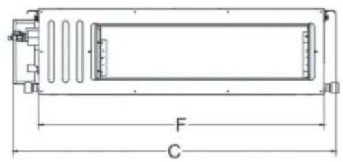
text_image
F C
natural_image
Technical line drawing of a mechanical or electronic component with no visible text, numbers, or symbols.
natural_image
Technical line drawing of a rectangular enclosure with horizontal slats and dimension labels A and B (no text or symbols beyond labels)
text_image
G EFig 4.1.1
Below are dimensions of A, B, C, etc. for different models:
Unit:mm (in.)
| Model | A | B | C | D | E | F | G |
| GMV-NDX42P/A-T(U) | 1440(56-11/16) | 500(19-11/16) | 1580(62-7/32) | 300(11-13/16) | 754(29-11/16) | 1400(55-1/8) | 700(27-9/16) |
| GMV-NDX48P/A-T(U) | 1440(56-11/16) | 500(19-11/16) | 1580(62-7/32) | 300(11-13/16) | 754(29-11/16) | 1400(55-1/8) | 700(27-9/ 16) |

text_image
C B D A G
text_image
I E H FFig 4.1.2
Below are dimensions of A, B, C, etc. for different models:
Unit: mm (in.)
| Model\Item | A | B | C | D | E | F | G | H | I |
| GMV-NDX54P/A-T(U) | 1353(53-1/4) | 632(24-7/8) | 992(39) | 1150(45-1/4) | 192(7-1/2) | 327(12-7/8) | 1483(58-3/8) | 791(31-1/8) | 385(15-3/16) |
| GMV-NDX72P/A-T(U) | 1353(53-1/4) | 632(24-7/8) | 992(39) | 1150(45-1/4) | 192(7-1/2) | 327(12-7/8) | 1483(58-3/8) | 791(31-1/8) | |
| GMV-NDX96P/A-T(U) | 1353(53-1/4) | 632(24-7/8) | 992(39) | 1150(45-1/4) | 192(7-1/2) | 327(12-7/8) | 1483(58-3/8) | 791(31-1/8) (31-1/8) | 385(15-3/16) |
4.1.2 Punching of Bolt Spots and Bolt Installation
(1) Cut out the installation paper pattern according to the hook installation dimension of unit. Place the installation paper pattern on the installation area as shown in Fig 4.1.3. Punch holes on the installation area according to the 4 spots on the paper pattern; the punching diameter may refer to the diameter of expansion bolt, about 60mm (2-3/8in.) to 70mm (2-3/4in.) depth, as shown in Fig 4.1.4.

text_image
Paper pattern Drill hole according to the hole siteFig 4.1.3
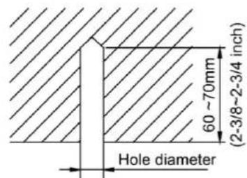
text_image
60 ~70mm (2-3/8~2-3/4 inch) Hole diameterFig 4.1.4
(2) Insert the expansion bolt M10 into the hole and then drive the iron nail into the bolt, as shown in Fig 4.1.5.
NOTICE! The length of bolt can be based on the height of room. Bolt should be prepared by the user.
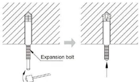
text_image
Expansion boltFig 4.1.5
4.1.3 Lift the Unit
Lift up the unit to the ceiling and secure it on the bolt. Use specialized nut to secure the unit.
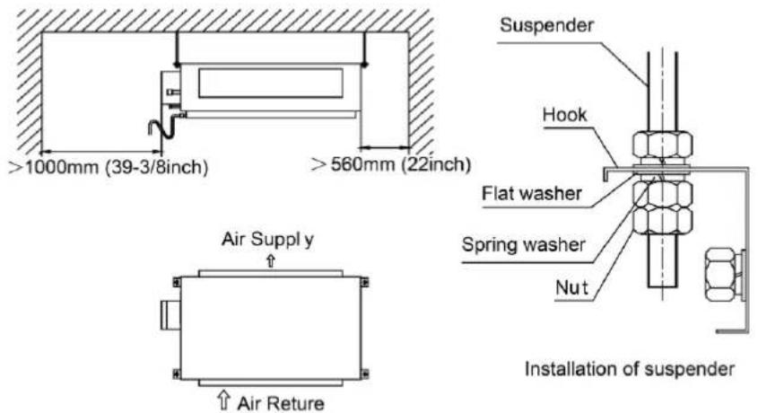
text_image
>1000mm (39-3/8inch) >560mm (22inch) Air Supply ↑ ↑ Air Reture Suspender Hook Flat washer Spring washer Nut Installation of suspenderFig 4.1.6
NOTICE!
① Before installation, please finish the preparation work of all pipes (connection pipe, drain pipe) and wires (wired controller wire, connection wire of IDU and ODU) that need to be connected with the indoor unit.
② Punch holes on the ceiling (air return opening or air outlet). Ceiling may have to be strengthened to make it level and to prevent it from vibration. You may consult user or constructor for details.
③ If the ceiling is not strong enough, you can install a beam bracket in a corner and secure the unit on the beam.
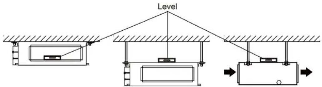
4.1.4 Horizontal Alignment
After the indoor unit is installed, remember to check the horizontal status of the whole unit. It should be horizontal from front to back and slant 1% from left to right, following the drainage direction, as shown in Fig 4.1.7.
text_image
LevelFig 4.1.7
4.2 Pipe Connection
(1) Direct the flaring of copper pipe to the center of screwed connection and then screw the flaring nut tight as shown in Fig 4.2.
(2) Use a torque wrench to tighten up the flaring nut until the wrench gives out a click sound.
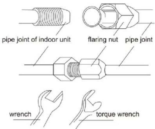
text_image
pipe joint of indoor unit flaring nut pipe joint wrench torque wrenchFig 4.2
Torque for tightening nut
| Pipe diameter (mm/in.) | Torque (N· m) |
| Φ6.35(1/4) | 15~30 |
| Φ9.52(3/8) | 35~40 |
| Φ12.7(1/2) | 45~50 |
| Φ15.9(5/8) | 60~65 |
(3) The pipe should not be bent too much or it may crack. Use a pipe bender when bending the pipe.
(4) Use a sponge to wrap the uninsulated connection pipe and the joint. Then tie it tight with a plastic tape.
4.3 Installation and Test of Drain Pipe
4.3.1 Installation of Drain Pipe
NOTICE!
① It is not allowed to connect the condensate drain pipe into waste pipe or other pipelines which are likely to produce corrosive or peculiar smell to prevent the smell from entering indoors or corrupt the unit.
② It is not allowed to connect the condensate drain pipe into rain pipe to prevent rain water from pouring in and cause property loss or personal injury.
③ Condensate drain pipe should be connected into special drain system for air conditioner.
④ The drain pipe should be as short as possible and slope downward for at least 1%\~2% so that condensate can drain out easily.
⑤ Size of the drainage hose must not be smaller than that of the drain pipe.
⑥ Install the drain pipe according to the following diagram and make it insulated. Improper installation will lead to water leakage and furniture and other objects may get wet.
⑦ You can buy local hard PVC pipe as drain pipe. When connecting the pipe, insert the end of PVC pipe into the drain hole and then tighten it up with a drain hose and cable tie. Do not use adhesives to connect drain hole and drain hose.
⑧ When the drain pipe is used for several equipments, the shared pipe should be about 100mm lower than the drain hole of each equipment. In this case, use thicker pipe.

text_image
additional drainage pipe insulating pipe insulating tape drainage pipe of indoor unitFig 4.3.1
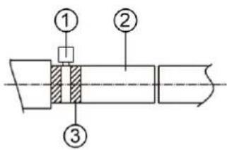
4.3.2 Drainage pipe installation
(1) Insert the drain hose into the drain hole and tighten it with tapes, as shown in Fig 4.3.2.
(2) Tighten the pipe clamp, with the distance between screw nut and hose smaller than 4mm.
① Metal clamp(accessory)
② Drain hose(accessory)
(3) Use sealing plate to make the pipe clamp and hose insulated, as shown in Fig 4.3.3.
① Metal clamp(accessory)
② Thermal sponge(accessory)
text_image
Technical diagram of a mechanical assembly with numbered components and cross-sectional viewFig 4.3.2

text_image
≤4mm (3/16inch)Fig 4.3.3
(4) When connecting several drain pipes, follow the instruction as indicated in Fig 4.3.4. Choose the drain collecting pipe that matches with unit capacity.

text_image
≥100(3-15/16) T Joint of Collecting PipeFig 4.3.4
(5) Install the trap as shown in following Fig 4.3.5.
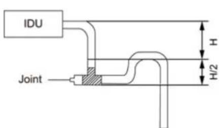
text_image
IDU Joint H H/2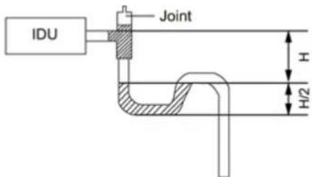
text_image
IDU Joint H H/2Fig 4.3.5
(6) Install one trap for each unit.
(7) Convenience for cleaning trap in the future should be considered when installing it.
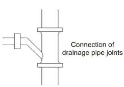
(8) The horizontal pipe can be connected to vertical pipe in the same level; please select
the connection way as shown in following fig.
NO.1: Connection of drainage pipe joints (Fig 4.3.6).
NO.2: Connection of downspout elbow (Fig 4.3.7).
NO.3: Inserting pipe connection (Fig 4.3.8).
text_image
Connection of drainage pipe jointsFig 4.3.6
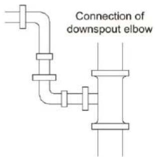
text_image
Connection of downspout elbowFig 4.3.7

text_image
Inserting pipe connectionFig 4.3.8
(9) Drain pipes should have a downward slope of at least 1%\~2%, in order to prevent pipes from sagging, install hanger bracket at intervals of 1000\~1500mm (39-3/8\~59in.).

text_image
1000~1500mm (39-3/8~59inch)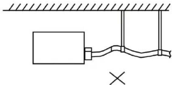
natural_image
Simple line drawing of a mechanical or electrical setup with a block, rope, and support structure (no text or symbols)Fig 4.3.9
4.3.3 Test of Drainage System
(1) Please test drainage system after electric work is finished. Inject approximately 1L purified water to drain pan from air vent, ensure that not to splash the water over the electrical components (e.g. water pump, etc).
(2) During the test, please carefully check the drainage joint, make sure no any leakage occur.
(3) It's strongly recommend to do the drain test before ceiling decoration.

text_image
Inject water
natural_image
Line drawing of a mechanical device with a hand holding a circular component (no text or symbols)Fig 4.3.10
4.4 Installation of Air Duct
NOTICE!
① There should be insulating layer on air-out duct, air-return duct and fresh air duct to
avoid heat loss and moisture. Adhere a nail on the air duct and then add thermal sponge with a layer of tin. Fasten it with a nail cover and then seal the junction with tin tapes, you can also use other materials that have good insulation quality.
② Each air-out duct and air-return duct should be fixed on a pre-made board with iron frame. The junction of air duct should be well-sealed in order to prevent air leakage.
③ The design and construction of air duct should comply with national requirements.
④ The edge of air-return duct is suggested to be more than 150mm (5-7/8in.) away from the wall. Add afilter to the air-return opening.
⑤ Please consider noise-damping and vibration damping for the design and construction of air duct. Besides, noise source must be away from people. For instance, do not have the air-return opening installed on top of the user (offices, rest area, etc.).
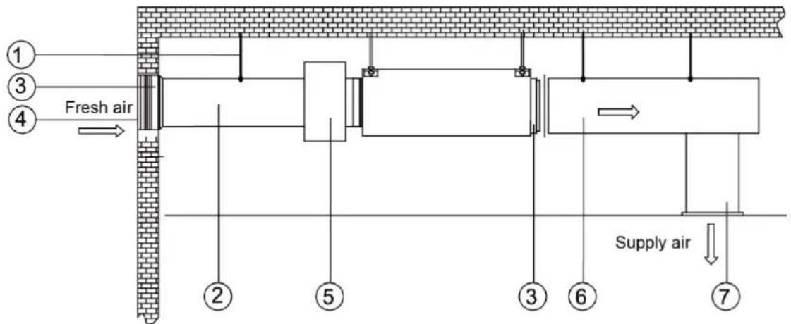
4.4.1 Installation of Air-out Duct
(1) Installation of the Rectangular Duct
text_image
① ③ ④ Fresh air ② ⑤ ③ ⑥ ⑦ Supply airFig 4.4.1
| No. | Name | No. | Name |
| 1 | Hanger Rod | 5 | Static Pressure Box |
| 2 | Fresh Air Duct | 6 | Main Supply Air Duct |
| 3 | Canvas Duct | 7 | Supply Air Outlet |
| 4 | Fresh Air Inlet |
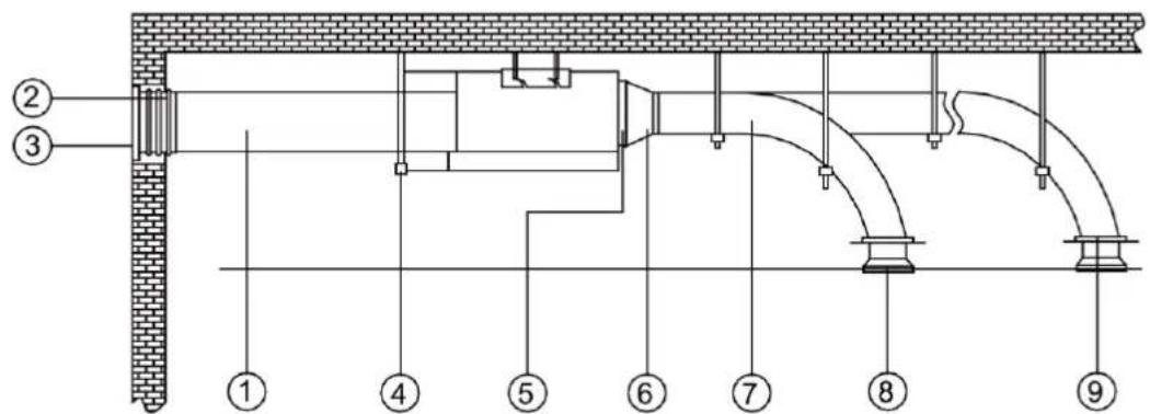
(2) Installation of Circular Duct
text_image
Technical diagram of a building facade with numbered components and structural connectionsFig 4.4.2
| No. | Name | No. | Name |
| 1 | Fresh Air Duct | 6 | Transition Pipe |
| 2 | Canvas Duct | 7 | Supply Air Duct |
| 3 | Fresh Air Blinds | 8 | Diffuser |
| 4 | Hanger Rod | 9 | Diffuser Connector |
| 5 | Supply Air Outlet |
4.4.2 Shape and Size of Air-outlet and Air-return Opening
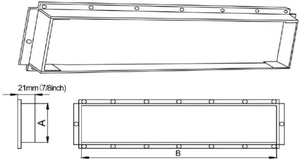
Fig 4.4.3 Air Outlet

text_image
D CFig 4.4.4 Air-Return Opening
Unit: mm (in.)
| Model | Size of Air Outlet | Size of Air –return Opening | ||
| A | B | C | D | |
| GMV-NDX42P/A-T(U) | 197 (7-3/4) | 1151 (45-5/16) | 1362 (53-5/8) | 264 (10-3/8) |
| GMV-NDX48P/A-T(U) | 197 (7-3/4) | 1151 (45-5/16) | 1362 (53-5/8) | 264 (10-3/8) |
| GMV-NDX54P/A-T(U) | 192(7-1/2) | 992(39) | 1150(45-1/4) | 327(12-7/8) |
| GMV-NDX72P/A-T(U) | 192(7-1/2) | 992(39) | 1150(45-1/4) | 327(12-7/8) |
| GMV-NDX96P/A-T(U) | 192(7-1/2) | 992(39) | 1150(45-1/4) | 327(12-7/8) |
4.5 Installation of Wired Controller
Please refer to User Manual of Wired Controller for the installation details.
NOTICE!
When installation is finished, the unit must be tested and debugged before operation. Please refer to Instruction Manual of ODU for auto addressing and debugging details.
5 Wiring Work
| ⚠WARNING |
| (1) Wiring should conform to national rules. All the parts, materials, electric work should be in accordance with local codes. |
| (2) Rated voltage and exclusive power supply should be used. |
| (3) Power cord should be fixed soundly and reliable. Never forcibly pull the power cord. |
| (4) Wire size of power cord should be large enough. The damaged power cord and connecting wire should be replaced by exclusive cable. |
| (5) All the electrical work should be performed by professional personnel as per local law, regulation and this manual. |
| (6) Connect the unit to the special earthing device and make sure the unit is earthed soundly. |
| (7) Air switch and circuit breaker is required to be set. Air switch should have both magnetic trip and thermal trip functions so as to protect the unit when short-circuit and overload happens. D-type breaker is advised to be used. |
| (8) Wiring diagram attached on the unit is prevailed. |
| (9) Before obtaining access to terminals, all supply circuits must be disconnected. |
| (10) If units are type I electrical appliances, they must be reliably grounded. |
| (11) Ground resistance must be in accord with requirements of local standard. |
| (12) The green-yellow wire within units are ground wire. Do not use it for other purposes. Nor should it be cut off or secured by tapping screws. Otherwise, it may cause electric shock. |
| (13) Power supply at user side must have reliable ground terminal. Do not connect ground wire to the following places:1 Water pipe.2 Gas pipe.3 Drainage pipe.4 Other places that are considered by professionals as unreliable. |
| (14) Power cord and communication wire should be separated, with a distance of more than 200mm (7-7/8in.). Otherwise, system's communication may not work well. |
5.1 Connection of Wire and Patch Board Terminal
(1) The connection of wire (as shown in fig 5.1.1)
1) Strip about 25mm (1in.) insulation of the wire end by stripping and cutting tool.
2) Remove the wiring screws on the terminal board.
3) Shape the tail of wire into ring by needle nose plier, and keep the gauge of ring in accordance with screw.
4) Use the screwdriver for tightening the terminal.
(2) The connection of stranded wire (as shown in fig 5.1.2)
1) Strip about 10mm (3/8in.) insulation of the end of stranded wire by stripping and cutting tool.
2) Loosen the wiring screws on terminal board.
3) Insert the wire into the ring tongue terminal and tighten by crimping tool.
4) Use the screwdriver for tightening the terminal.

text_image
single branch wire 25mm(1inch) insulation layerFig 5.1.1
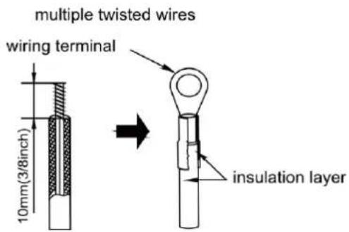
text_image
multiple twisted wires wiring terminal 10mm(3/8inch) insulation layerFig 5.1.2
5.2 Power Cord Connection
| ⚠WARNING |
| (1) Every unit should be equipped with a circuit breaker for short-circuit and overload protection. |
| (2) During operation, all indoor units connected to the same outdoor unit system must be kept energized status. Otherwise, the unit can’t operate normally. |
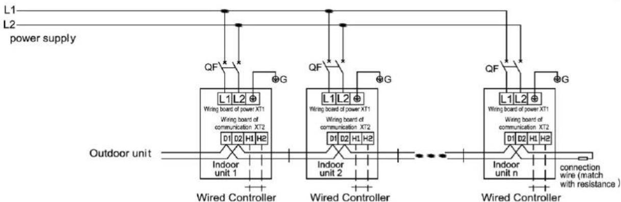
text_image
L1 L2 power supply QF G L1L2 Wiring board of power XT1 Wiring board of communication XT2 D1 D2 H1 H2 Indoor unit 1 Outdoor unit Wired Controller QF G L1L2 Wiring board of power XT1 Wiring board of communication XT2 D1 D2 H1 H2 Indoor unit 2 Wired Controller QF G L1L2 Wiring board of power XT1 Wiring board of communication XT2 D1 D2 H1 H2 Indoor unit n connection wire (match with resistance) indoor unit n connection wire (match with resistance)Fig 5.2.1
For units with single-phase power supply.
(1) Detach the electric box lid.
(2) Let the power cord pass through the wiring through-holes.
(3) Connect the power cord to terminal "L1, L2, ♣".
(4) Fix the power card with wiring clamp.
5.3 Connection of Communication Line of IDU and ODU
(1) Detach the electric box lid.
(2) Let the Communication cable pass through the wiring through-holes.
(3) Connect the communication wire to terminal D1 and D2 of indoor 4-bit wiring board, as shown in fig5.3.1.
(4) Fix the communication cable with clamp of electric box.
(5) For more reliable communication, make sure connect the terminal resistor to the most downstream IDU of the communication bus (terminal D1 and D2), as shown in fig 5.3.2, terminal resistor is provided with each ODU.
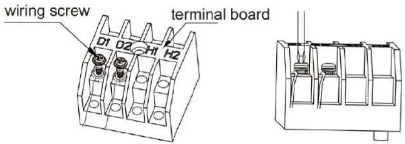
text_image
wiring screw terminal board D1 D2 H1 H2Fig 5.3.1

flowchart
graph TD
    A["INDU PCB"] --> B["communication interface CN12"]
    B --> C["previous IDU"]
    B --> D["match resistance for communication"]
    style A fill:#f9f,stroke:#333
    style B fill:#ccf,stroke:#333
    style C fill:#cfc,stroke:#333
    style D fill:#fcc,stroke:#333
Fig 5.3.2
5.4 Connect Communication Wire of Wired Controller
(1) Open electric box cover of indoor unit.
(2) Let the communication wire go through the rubber ring.
(3) Connect the communication wire to terminal H1 and H2 of indoor 4-bit wiring board.
(4) Fix the communication wire with wire clip on the electric box.
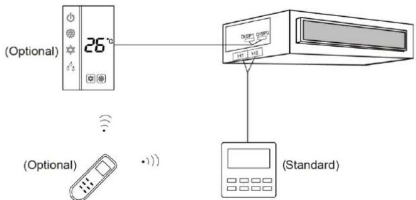
(5) Wiring instructions of remote receiving light board and wired controller:
1) Fig 5.4.1 shows the installation of wired controller.

text_image
DISP1 DISP2 H1 H2 (Standard) (Optional) 26°C (Optional) (Optional)Fig 5.4.1
Fig 5.4.2
2) Fig 5.4.2 shows the installation of remote controller.
3) Wired controller and receiving light board can be installed at the same time. When operating through a remote controller, both wired controller and the receiving light board can receive the signals, as shown in Fig 5.4.3.
text_image
(Optional) 26°C DSP DSP2 141 142 (Optional) (Optional) (Standard)Fig 5.4.3
5.5 Illuminate for Connection of Wired Controller and Indoor Units Network
(1) Communication wire of indoor unit and outdoor unit (or indoor unit) is connected to D1, D2.
(2) Wired controller is connected to H1, H2.
(3) One indoor unit can connect two wired controllers that must be set as master one and slave one.
(4) One wired controller can control 16 indoor units in maximum at the same time. (as shown in fig 5.5)
NOTICE!
① When the wired controller is controlling multiple indoor units at the same time, the indoor units must be of the same model. Fresh air indoor unit cannot share the same wired controller with other types of VRF indoor unit.
② When two wired controllers are controlling the indoor units, you need to set an address for each wired controller. Address No.1 refers to master wired controller while address No.2 refers to sub-master wired controller. They should not share the same address. For specific setting methods, please refer to installation manual of wired controller.
③ If connecting the fresh air indoor unit with wired controller for operation, fresh air indoor unit code "FAP" will be displayed. For specific operation methods, please refer to instruction manual of wired controller.

flowchart
graph TD
    A["Top Unit"] --> B["D1 D2"]
    A --> C["D1 D2"]
    B --> D["Device 1"]
    B --> E["Device 2"]
    C --> F["Device 3"]
    C --> G["Device 4"]
    D --> H["Control Panel"]
    E --> I["Control Panel"]
    F --> J["Control Panel"]
    G --> K["Control Panel"]
    H --> L["Display Module"]
    I --> M["Display Module"]
    J --> N["Display Module"]
    K --> O["Display Module"]
    L --> P["Display Module"]
    M --> Q["Display Module"]
    N --> R["Display Module"]
    O --> S["Display Module"]
    P --> T["Display Module"]
    Q --> U["Display Module"]
Fig 5.5
6 Routine Maintenance
| ▲WARNING |
| (1) Do turn off the unit and cut off the main power supply when cleaning the air conditioner to avoid electric shock or injury. |
| (2) Stand at solid table when cleaning the unit. |
| (3) Do not clean the unit with hot water whose temperature is higher than 45°C (113°F) to prevent fade or deformation. |
| (4) Do not dry the filters by fire, or it may catch fire or become deformed. |
| (5) Clean the filter with a wet cloth dipped in neutral detergent. |
| (6) Please contact after-sales service staff if there is abnormal situation. |
6.1 Cleaning of Filter
(1) Remove the filters from inlet of IDU. Use a vacuum cleaner to remove dust. If the filters are dirty, wash them with warm water and mild detergent, and dry the filters in the shade.
(2) If the unit used in the environment with much dust, please clean it regularly (Usually once every two weeks).
6.2 Maintenance before the Seasonal Use
(1) Check if the air inlet and air outlet of indoor and outdoor unit are blocked.
(2) Check if securely grounded.
(3) Check if all the power cord and communication cable are securely connected.
(4) Check if any error code displayed after energized.
6.3 Maintenance after the Seasonal Use
(1) Set the unit in fan mode for half a day in a sunny day to dry the inner part of unit.
(2) When the unit won't be used for a long time, please cut off power supply for energy saving, the characters on the wired controller screen will disappear after cutting off the power supply.
7 Table of Error Codes for Indoor Unit
| Error Code | Content | Error Code | Content | Error Code | Content |
| L0 | Indoor Unit Error | LA | Indoor Units Incompatibility Error | d9 | Jumper Cap Error |
| L1 | Indoor Fan Protection | LH | Low Air Quality Warning | dA | Indoor Unit Network Address Error |
| L2 | E-heater Protection | LC | ODU-IDU Incompatibility Error | dH | Wired Controller PCB Error |
| L3 | Water Full Protection | d1 | Indoor Unit PCB Error | dC | Capacity DIP Switch Setting Error. |
| L4 | Wired Controller Power Supply Error | d3 | Ambient Temperature Sensor Error | dL | Outlet Air Temperature Sensor Error |
| L5 | Freeze protection | d4 | Inlet Pipe Temperature Sensor Error | dE | Indoor Unit CO2 Sensor Error |
| L7 | No Master Indoor Unit Error | d6 | Outlet Pipe Temperature Sensor Error | dy | Water Temperature Sensor Error |
| L8 | Power Insufficiency Protection | d7 | Humidity Sensor Error | C0 | Communication Error |
| L9 | Quantity Of Group Control Indoor Units Setting Error | d8 | Water Temperature Error | AJ | Filter Cleaning Reminder |
| db | Special Code: Field Debugging Code | ||||
8 Troubleshooting
If your air conditioner is not working well, please check the following table first before asking for service:
| Phenomenon | Troubleshooting |
| The unit can't start. | 1 Power supply is not connected.2 Circuit breaker tripping caused by leakage of electricity.3 Input voltage is too low.4 Operation button is off.5 Error of control loop . |
| The unit stops after running for a while. | 1 There is obstacle in front of condenser.2 Error of control loop.3 Perform cooling when outdoor ambient temperature is higher than 43 °C (109 °F. |
| Poor cooling effect. | 1 The filter is dirty or blocked.2 Too heavy heat load of room (e.g. too many people).3 Door or windows is open.4 Air inlet and outlet of IDU are blocked.5 Set temperature is too high or refrigerant leaks.6 The performance of room temperature sensor gets worse. |
| Poor heating effect. | 1 The filter is dirty or blocked.2 Door or window is open.3 Set temperature is too low.4 Refrigerant leaks.5 Outdoor ambient temperature is lower than -5 °C (23 °F).6 Error of control circuit. |
| Indoor fan doesn't start up during heating. | 1 Position of tube temperature sensor is improper.2 Tube temperature sensor is not inserted well.3 Wiring of tube temperature sensor breaks off.4 Electrical leakage of capacitor. |
NOTICE!
If air conditioner still fails to work normally after checking and handling as described above, please stop using it immediately and contact local service center for assistance.
natural_image
Architectural architectural detail showing modern building facades and structural elements (no text or symbols)
GREE
GREE ELECTRIC APPLIANCES, INC. OF ZHUHAI
Add: West Jinji Rd, Qianshan, Zhuhai, Guangdong, China, 519070
Tel: (+86-756) 8522218
Fax: (+86-756) 8669426
E-mail: gree@gree.com.cn www.gree.com

66170050104