
B1PAC07 - Washing machine Aconatic - Free user manual and instructions
Find the device manual for free B1PAC07 Aconatic in PDF.

| Product Type | Portable Air Conditioner |
| Brand | Aconatic |
| Model | B1PAC07 |
| Rated Voltage | 220V |
| Rated Frequency | 50Hz |
| Rated Input Power | 750W |
| Rated Current | 3.4A |
| Cooling Capacity | 7000 BTU/h (2000W) |
| Moisture Removal | 0.6 L/h |
| Air Flow | 250 m³/h |
| Operating Modes | Cooling, Drying, Fan, Auto |
| Fan Speeds | Low, High |
| Timer Range | 1–24 hours (Auto-On/Off) |
| Sleep Mode | Yes (only in cooling mode) |
| Remote Control | Included (CR2025 battery) |
| Air Filter Cleaning Interval | Every 2 weeks |
| Drain Port Type | Stopper with optional hose connection |
| Exhaust Hose | Included (length adjustable) |
| Window Adapter | Included |
| Castors | Yes (for mobility) |
| Minimum Clearance Around Unit | 30 cm |
| Safety Features | Protective device trips at extreme temperatures (below 15°C or above 43°C) |
Frequently Asked Questions - B1PAC07 Aconatic
User questions about B1PAC07 Aconatic
0 question about this device. Answer the ones you know or ask your own.
Ask a new question about this device
Download the instructions for your Washing machine in PDF format for free! Find your manual B1PAC07 - Aconatic and take your electronic device back in hand. On this page are published all the documents necessary for the use of your device. B1PAC07 by Aconatic.
USER MANUAL B1PAC07 Aconatic
natural_image
Technical line drawing of a large industrial air conditioner unit with multiple side-mounted fans and wheels, shown with an arrow indicating direction (no text or symbols present)รีโมควบคุม
natural_image
Pure mechanical component diagram showing a shaft and flange with threaded ends (no text or symbols)รูปที่ 1

natural_image
Technical line drawing of a cylindrical mechanical component with concentric grooves (no text or symbols)natural_image
Technical line drawing of a coiled pipe or duct assembly with directional arrow (no text or symbols)natural_image
Technical line drawing of a mechanical device with internal tubing and a spool, no text or symbols presentการดำเนินงาน
Portable Air-conditioner User's Manual
Model
B1PAC07
Please read this user's manual carefully to ensure proper use, maintenance and installation
PARTS DESCRIPTION

- Control panel
- Air outlet
- Signal receptor
- Remote control
- Handle
- Air exhaust hose
- Air inlet
- Drain port (inserted by a stopper)
- Hose connector
- Window adaptor
- Pull tab of the air filter
- Castor

natural_image
Technical line drawing of a large industrial machine with multiple side-mounted heat exchangers and wheels (no text or symbols)Remote control
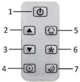
This unit has a remote control. One piece of CR2025 battery will be provided with the remote control. Before starting to use the remote control, remove the plastic protection from the battery. If you want to change the battery, please refer to the instruction behind the remote control. If it is not in use for a long time, please take the battery out of the remote control. The functions of the remote control buttons are listed below.
- Power button
- Temperature/timer increasing button
- Temperature/timer decreasing button
- Timer on/off button
- Mode button
- Wind speed button
- Sleep button
Control panel
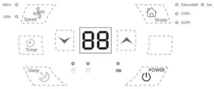
Temperature/timer increasing button
Temperature/timer decreasing button
More button
COOL /Fan /Dehumidift /AUTO
Timer indicator light Sleep indicator light
INSTALLATION
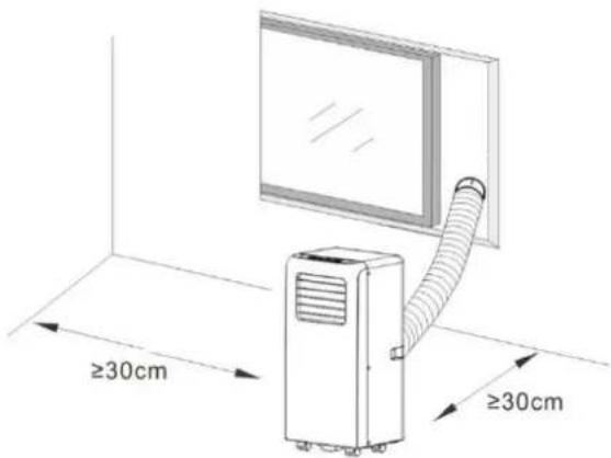
- The unit shall be installed on a flat surface where the air outlet would not be blocked. The required distance around the unit should be at least 30cm. (Fig.1)
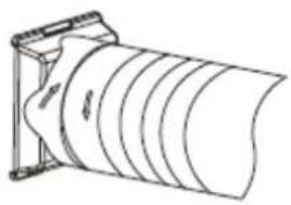
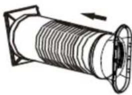
- The unit shall not be installed in a laundry room. - Extend the air exhaust hose by drawing out the two ends of the hose.

natural_image
Pure mechanical diagram showing a shaft and flange with no text or symbols- Screw the air exhause hose into the hose connector.
natural_image
Technical line drawing of a cylindrical mechanical component with internal grooves (no text or symbols)- Screw the other end of air exhause hose into the window adaptor.
natural_image
Technical line drawing of a coiled pipe or duct assembly with directional arrow (no text or symbols)- Insert the hose connector into the bracket on the back of the unit.

natural_image
Technical line drawing of a mechanical device with a coiled cable and housing (no text or symbols)OPERATION
*Always let the appliance rest for at least 2 hours after moving it from one location to another.
Before use, check up whether the exhaust hose has been mounted properly. Plug in the appliance.
1. Power button
Press the power button to turn on the appliance. Press the button again, the appliance will be turned off.
2. Temperature/timer increasing button & temperature/timer decreasing button
Press the button “/” to set your desired room temperature from 15°C to 31°C. The buttons can also be used for timer adjustment during timer setting. The value will be increased/decreased by 1 (°C/hour) for each press.
3. Fan speed button
Press the fan speed button to switch the fan speed between low and high. The corresponding indicator light “LOW”/“HIGH” will illuminate.
4. Mode button
Press the mode button to choose your desired working mode among cooling, drying and fan. The corresponding indicator light will turn on when the specific mode is selected.
- Auto mode
In AUTO mode, the indoor temperature sensor operates automatically to select the desired operation with cooling or fan: when the room temperature is no less than 24 °C, the unit automatically selects cooling mode, and when the room temperature is less than 24 °C, the unit automatically selects fan mode.
- Drying mode
The centrifugal fan runs at a low speed. The fan speed and temperature cannot be adjusted.
The compressor will stop after 8 minutes of running and then run again after 6 minutes.
- Cooling mode
When the room temperature is higher than the set temperature, the compressor starts to run.
When the room temperature is lower than the set temperature, the compressor stops and the fan operates at the original set speed.
Note: When the compressor is working, the unit will vibrate slightly. This is normal and harmless.
- Fan mode
When the fan runs at the set speed, the compressor does not
run.
The adjustment of temperature in
Fan mode is not effective.
turn on once the select time passed.
Auto-OFF setting
- When the appliance is ON, press the timer button, the timer indicator light will flash.
- Press the timer increasing or decreasing button to select a desired auto-OFF time from 1 to 24 hours. (When using WIFI connection and setting on your phone, this range is 1 to 23 hours.) The digital display and timer indicator light will flash for several seconds, then the timer setting is confirmed and the timer indicator light will illuminate still.
- The appliance will automatically turn off once the select time has passed.
5. Timer button
Auto-ON setting
- When the appliance is OFF, press the timer button, the timer indicator light will flash.
- Press the timer increasing or decreasing button to select a desired auto-ON time from 1 to 24 hours. (When using WIFI connection and setting on your phone, this range is 1 to 23 hours.) The digital display and timer indicator light will flash for several seconds, then the timer setting is confirmed and the timer indicator light will illuminate still.
- The appliance will automatically
To cancel the timer, set the time to 0 hour, or press into the timer setting, and when the digital display flashes, press the timer button again. The timer indicator light will then turn off.
6. Sleep button (only active in cooling mode)
Press the sleep button to activate the sleep mode. The sleep indicator light turns on.
In sleep mode, the fan turns to low speed automatically. The set temperature will increase 1 °C after one hour, and increase 2 °C after two hours. After six hours, the appliance stops running automatically.
NOTE:
- The appliance can memorize the settings you have made except for
the timer setting.
- The protective device may trip and stop the appliance in the conditions listed below.
| Cooling | Room temperature is over 43°C. |
| Room temperature is below 15°C. | |
| Drying | Room temperature is below 15°C. |
- If the appliance runs in cooling or drying mode with door or window opened for a long time when relative humidity is above 80%, dew may drip down from the air outlet.
Drain water
1) Special reminder: There is condensing water recycling hidden in this appliance. The condensing water is partly kept recycling between the condenser and the water plate. When the water level
rises to the upper level, the water-full code “E4” will be shown on the digital display to remind of draining water.
2) Please cut off the power supply, move the appliance to a suitable place, pull out the stopper in the drain port to drain the water completely. If conditions permitted, you can also connect the drain hose to the drain port for the water draining.
3) After the draining, insert back the stopper to the drain port, otherwise the appliance may leak and make your room wet.
CLEANING AND MAINTENANCE
- Before cleaning, be sure to disconnect the appliance from any electric supply outlet.
- Do not use gasoline or other
chemicals to clean the appliance.
- Do not wash the appliance directly.
- If the appliance is damaged, please contact the dealer or repair shop.
Air Filter
If the air filter becomes clogged with dust/dirt, the air filter should be cleaned once every two weeks.
- Pull out the air filter from the air inlet grille by the pull tab.
- Clean the air filter with neutral detergent in lukewarm water (< 40°C) and dry it up in the shade.
- Reinstall the air filter.
Clean the Surface
First clean the surface with a neutral detergent and wet cloth, and then wipe it with a dry cloth.
| Troubles | Possible Causes |
| Not cool enough | The doors or windows are not closed. |
| There are heat sources inside the room. | |
| The hot air exhaust hose is not connected or blocked. | |
| Temperature setting is too high. | |
| Air inlet is blocked. | |
| Noisy | The ground is not level or not flat enough. |
| The sound comes from the flowing of the refrigerant inside the appliance. | |
| Code “E2” on the digital display | Room temperature sensor failed. |
| Code “E3” on the digital display | Evaporator temperature sensor failed. |
| Code “E4” on the digital display | Water-full warning- 10 - |
TECHNICAL DATA
Below data for your operating
reference
| Model | B1PAC07 |
| Rated voltage | 220V |
| Rated frequency | 50Hz |
| Rated input | 750W |
| Rated current | 3.4A |
| Cooling capacity | 7000BTU/2000W |
| Moisture removal (L/H) | 0.6 |
| Air flow | 250m3/h |
- รีโมควบคุม
- การดำเนินงาน
- Portable Air-conditioner User's Manual
- PARTS DESCRIPTION
- Remote control
- Control panel
- COOL /Fan /Dehumidift /AUTO
- INSTALLATION
- OPERATION
- Power button
- Temperature/timer increasing button & temperature/timer decreasing button
- Fan speed button
- Mode button
- Auto-OFF setting
- Timer button
- Auto-ON setting
- Sleep button (only active in cooling mode)
- NOTE:
- Drain water
- CLEANING AND MAINTENANCE
- Air Filter
- Clean the Surface
- TECHNICAL DATA
- Below data for your operating
Brand : Aconatic
Model : B1PAC07
Category : Washing machine