AMPMA40X - Blender OWI - Free user manual and instructions
Find the device manual for free AMPMA40X OWI in PDF.

User questions about AMPMA40X OWI
0 question about this device. Answer the ones you know or ask your own.
Ask a new question about this device
Download the instructions for your Blender in PDF format for free! Find your manual AMPMA40X - OWI and take your electronic device back in hand. On this page are published all the documents necessary for the use of your device. AMPMA40X by OWI.
USER MANUAL AMPMA40X OWI
40 Watt Mini Digital Amplifier with EQ/Mixer

IR Remote Control Model AMPIRMA40X
Table of Contents
- Introduction ...... 3
- Features....3
- Specification.... 4
- Audio Connection.... 5
- Buttons Control 8
- RS232 Communication Protocol.... 10
- System Diagram 12
- Panel Drawing.... 13
- AMPIRMA40X Instruction Sheet....13
1. Introduction
AMPMA40X is a compact-size digital amplifier (Class-D) with 3 inputs(2 line in and 1 balanced MIC). It is integrated with powerful functions, including bridge connection, dual-mono, EQ control, microphone mixer etc.
It has a good application in different places, including classroom, small meeting room, lecture hall, bar, pub etc.
2. Features
- Two stereo audio inputs, switchable by button, IR remote & RS232.
● Volume/Bass/Treble controllable by buttons IR remote & RS232. - 2x20Watt@4Ohm as the default amplifier output.
● Line audio output at 3.5mm jack, with volume controllable. - Bridge connection function. User can switch the AMPMA40X to be 1x40Watt@8Ohm by bridge connection.
- Dual-mono function. User can sum up the stereo audio to two times mono audio.
- MIC mixer function. The microphone will be mixed to the line audio output, and be controlled separately.
- MIC input supports 48V phantom power, dynamic MIC and wireless MIC.
- MIC port can support balance/unbalance signal, suppress the external noise effectively.
- Auto noise gate. It keeps detecting the audio and MIC input, will mute the output when there is no input.
- Ultra low inrush current, no need for power sequencing. This allows multiple AMPMA40X to be powered on simultaneously without overloading power circuits.
- Convection cooler, fan is not needed.
- Antistatic case design: providing good protection for long-term and stable performance
● LED indicator, for power and working status. - IR Remote Control Model AMPIRMA40X available (sold separately)
3. Specification
| Audio Input | Audio Output | ||
| Input 1 | 1 ea. stereo audio (L & R RCA) | Output 1 | 1 ea. amplifier, |
| Input 2 | 1 ea. stereo audio (3.5 mini jack) | Output 2 | 1 ea. stereo audio |
| Input 3 | 1 ea. MIC | ||
| Input Connector 1 | 2 ea. RCA L/R | Output Connector 1 | 1 ea. captive screw connector |
| Input Connector 2 | 1 ea. 3.5 mm jack stereo | Output Connector 2 | 1 ea. 3.5 mm jack (Stereo or Mono) |
| Input Connector 3 (Mic) | 1 ea. captive screw connector, | ||
| Input Impedance | >10KΩ | Output Impedance | 50Ω/stereo,4~8Ω/Amplifier |
| Audio General | |||
| Frequency Response | 20Hz ~ 20KHz | CMRR | >70dB@20Hz~20KHz |
| SNR | 80dB at maximum output | Bandwidth | 20Hz ~ 25KHz |
| Stereo Channel Separation | >75dB@20Hz to 20KHz | THD + Noise | 1%@1KHz,0.3%@20KHz at nominal level |
| Voltage Gain | 32dB | Power Output | 2x20 Watts (4 Ohms) |
| Control Function | |||
| RS232 Control | Captive Screw Connector | ||
| IR Remote | IR Remote Control | ||
Mini Digital Amplifier, with MIC Mixer and EQ
General
| Max DCCompensation | 1.5V | Humidity | 10% ~ 90% |
| Temperature | -20°C ~ +70°C | Power Consumption | 24VDC, 3A |
| Power Supply | 100VAC ~ 240VAC, 50/60Hz | Product Weight | 0.5Kg |
| Case Dimension | 4 7/8” W x 3 7/16” L x 1.5” D(H) | ||
| 123mm W x 87mm L x 38mm D(H)(Wall/Table mountable) | |||
NOTE: All nominal levels are at ±10%.
4. Audio Connection
4.1 Audio Output
4.1.1 Default output: 2x20Watt@4Ohm
The default output of amplifier is 2x20Watt@4Ohm, so user can connect the amplifier output in the regular way. As the picture below:

text_image
regular way. As the picture below: MONO STEREO BRIDGE IR RS232 Tx+Rx + - MIC 48V LINE L R 1 2 INPUTS Switching to the "STEREO" MONO STEREO BRIDGE 24V CE 1x40Watt@8Ω + 2x20Watt@4Ω + LOOP OUTPUTS Speaker SpeakerConnecting the four pins, like this
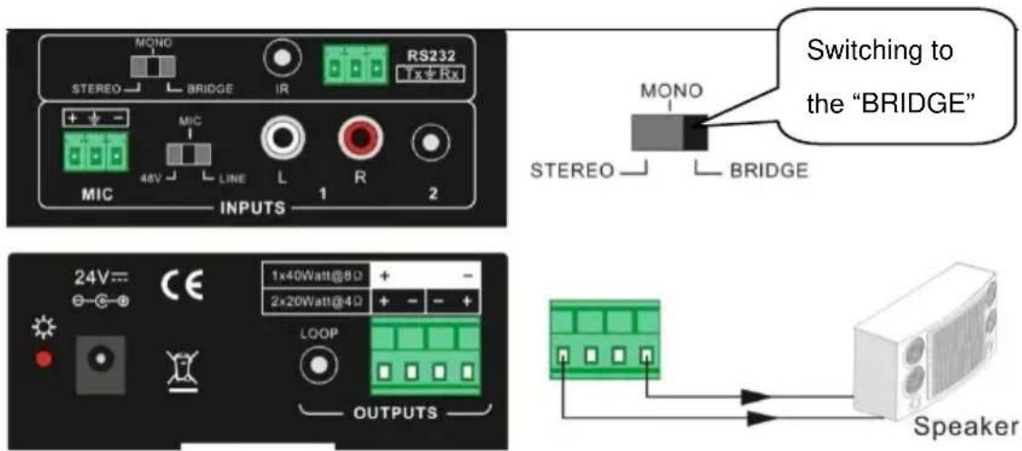
4.1.2 Bridge connection: 1x40Watt@8Ohm
The AMPMA40X has the bridge connection, to double the output power at 1x40Watt@8Ohm. It will sum up the input left channel and input right channel to be mono output, and the power is up to 40Watt.
The bridge connection is:
text_image
MONO STEREO BRIDGE IR RS232 + - MIC 48V LINE L R 1 2 MIX INPUTS Switching to the "BRIDGE" MONO STEREO BRIDGE 24V= CE 1x40Watt@80 + 2x20Watt@40 + LOOP OUTPUTS SpeakerConnecting the two pins. like this
4.1.3 Dual-mono output:
The AMPMA40X also has the function of double-mono output. It can sum up the left and right channel, to be the mono audio output. In this way, the both of the outputs are showing the same mono audio.
The connection is:

text_image
The connection is: MONO STEREO BRIDGE IR RS232 Tx/Rx + - MIC 48V LINE L R 1 2 MIX INPUTS 24V= CE 1x40Watt@8Ω + - 2x20Watt@4Ω + - OUTPUTS LOOP Switching to the "MONO" MONO STEREO BRIDGE Speaker SpeakerConnecting the four pins, like this
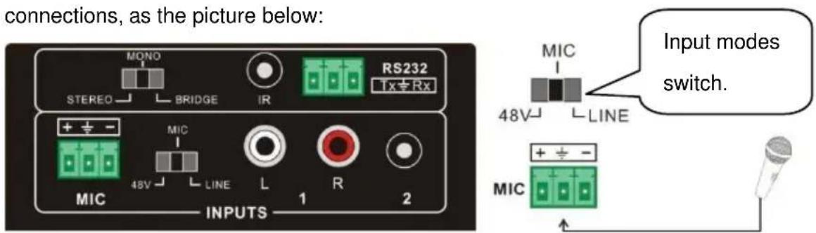
4.2 Microphone input
The microphone input of AMPMA40X has three modes, and different modes use different connections, as the picture below:
text_image
connections, as the picture below: MONO STEREO BRIDGE IR RS232 1x Rx + ± - MIC 48V LINE L R 2 INPUTS 1 2 Input modes switch. MIC + ± -4.2.1 48V phantom power input
When the switch turns to "48V", the MIC input will provide a 48V phantom power. This is usually used for power supply for condenser microphone, Connection is:
“+” connects to positive, “-” connects to negative and “±” to ground.
NOTICE: In this mode, only condenser microphone can be connected with.
4.2.2 MIC input
When the switch turns to "MIC", the microphone input is used for connecting with dynamic microphone. There are two different connections:
1) Unbalanced connection:
a) “ ± ” connects to ground, and “-” connects to signal.
b) “ ± ” connects to ground, and “+” connects to signal.
2) Balanced connection: “+” connects to positive, “-” connects to negative and “ ± ” connects to ground.
4.2.3 LINE input
When the switch turns to "LINE", the microphone input is used for connecting with normal audio or wireless microphone output. There are two different connections:
1) Unbalanced connection:
a) “ ± ” connects to ground, and “-” connects to signal.
b) “ ± ” connects to ground, and “+” connects to signal.
2) Balanced connection: “+” connects to positive, “-” connects to negative and “±” connects to ground.
5. Buttons Control
The buttons provides the control of volume/EQ control and switching.
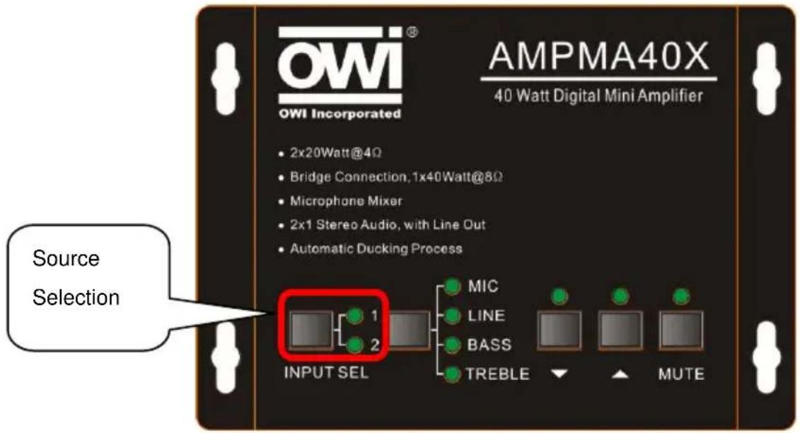
5.1 Audio switching
There are two switchable stereo audio inputs, one 2xRCA input, and one 3.5mm jack input, switchable through the buttons as below:
text_image
OWI® OWI Incorporated AMPMA40X 40 Watt Digital Mini Amplifier • 2x20Watt@4Ω • Bridge Connection, 1x40Watt@8Ω • Microphone Mixer • 2x1 Stereo Audio, with Line Out • Automatic Ducking Process Source Selection INPUT SEL MIC LINE BASS TREBLE MUTE5.2 Volume/EQ controlling
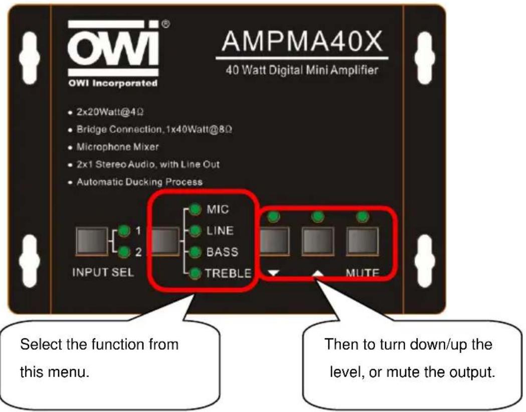
The line volume and MIC volume can be controlled by the buttons.
The MIC Volume/LINE volume/LINE bass/LINE treble will be selected by the buttons, and controlled up/down/mute by the function buttons. Please check the picture below:
text_image
OWI® OWI Incorporated AMPMA40X 40 Watt Digital Mini Amplifier • 2x20Watt@4Ω • Bridge Connection, 1x40Watt@8Ω • Microphone Mixer • 2x1 Stereo Audio, with Line Out • Automatic Ducking Process INPUT SEL MIC LINE BASS TREBLE MUTE Select the function from this menu. Then to turn down/up the level, or mute the output.For example, to turn up the line volume, you should select the "LINE" first, and then press the button "”.
6. RS232 Communication Protocol:
Baud rate: 9600
Data bit: 8
Stop bit: 1
Parity bit: none
| Command | Function Description | Feedback Code |
| 1A1. | Switching the audio to input 1 | A: 1 -> 1 |
| 2A1. | Switching the audio to input 2 | A: 2 -> 1 |
| 0A0. | Mute Audio of MIC and Line out | Mute Audio |
| 1A0. | Mute audio of MIC | Mute MIC |
| 2A0. | Mute audio of line out | Mute LIN |
| 0A1. | Unmute Audio | Unmute Audio |
| 600% | Checking the working status | A: 1 -> 1Volume: 30Bass: 00Treble: 00 |
| 601% | MIC volume up | Volume of MIC: 51 |
| 602% | MIC volume down | Volume of MIC: 51 |
| 603% | Line volume up | Volume of LINE: 51 |
| 604% | Line volume down | Volume of LINE: 51 |
| 605% | Bass level up | Bass of LINE: 04 |
| 606% | Bass level down | Bass of LINE: 04 |
| 607% | Treble level up | Treble of LINE: 04 |
| 608% | Treble level down | Treble of LINE: 04 |
| 609% | Initialization, back to the default setting | A: 1 -> 1Volume: 50Bass: 04Treble: 04 |
| 5[x][x]% | Preset MIC volume, [xx] arranges from [00] to [60].61 degrees in total. | Volume of MIC: 50 |
| 7[x][x]% | Preset line volume, [xx] arranges from [00] to [60].61 degrees in total. | Volume of LINE: 50 |
| 8[x][x]% | Preset the bass level, [xx] arranges from [00] to [08].9 degrees in total. | Bass of LINE: 04 |
| 9[x][x]% | Preset the treble level, [xx] arranges from [00] to [08].9 degrees in total. | Treble of LINE: 04 |
Notice:
1: The letter inside bracket [ ] is the variable code, which is the changeable.
2: The bracket [ ] is not included to the RS232 commands.
3: Any dot “.” after the letters is part of the commands.
Example 1:
Switching the input 2 to the line out. We should send the RS232 command: [2A1.]
Example 2:
Turning up the volume of line audio. We should send the RS232 command: [603%]
Example 3:
Preset the MIC volume to "21" degree. We should send the RS232 command: [521%]
Example 4:
Checking the working status of AMPMA40X. We should send the RS232 command: [600%]
7. System Diagram
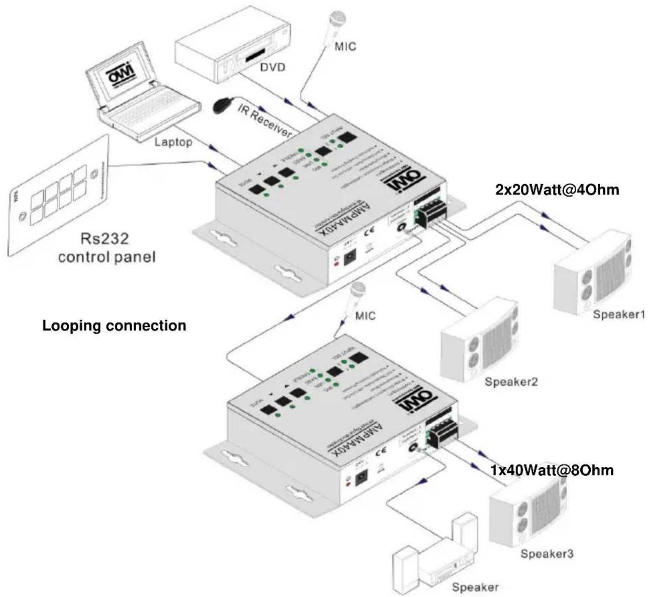
flowchart
graph TD
    A["OMi"] -->|Laptop| B["IMo4Max 40X"]
    C["DVD"] -->|IR Receiver| B
    D["Speaker1"] -->|2x20Watt@4Ohm| B
    E["Speaker2"] -->|1x40Watt@8Ohm| B
    F["Speaker3"] -->|1x40Watt@8Ohm| B
    G["Laptop"] -->|Looping connection| B
    H["ICM"] --> B
    I["2x20Watt@4Ohm"] --> B
    J["1x40Watt@8Ohm"] --> B
- Panel Drawing
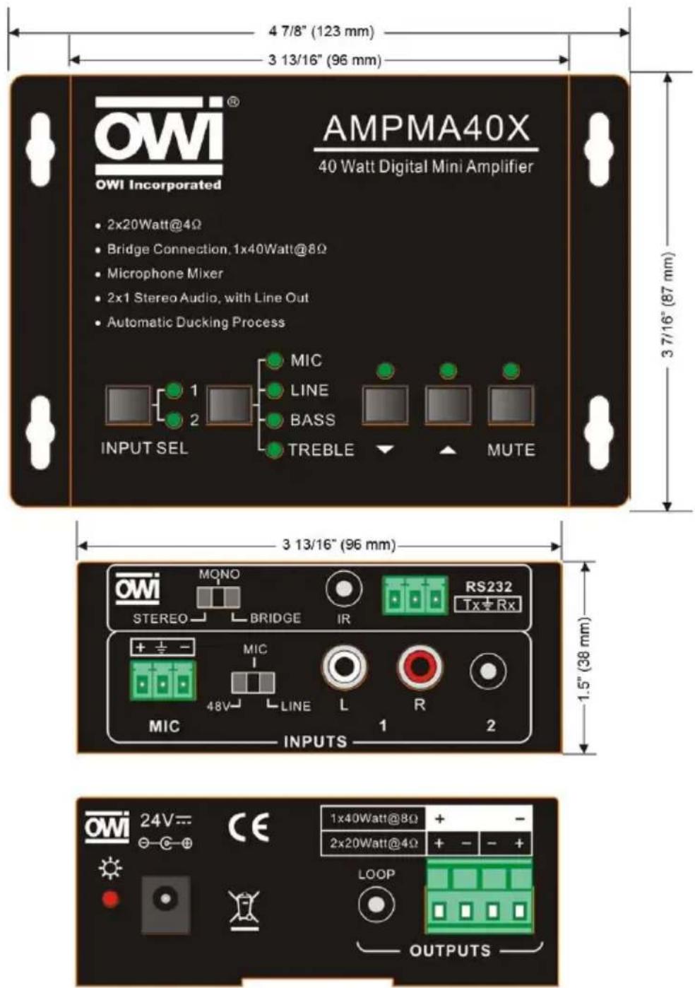
text_image
OWI Incorporated AMPMA40X 40 Watt Digital Mini Amplifier 2x20Watt@4Ω Bridge Connection.1x40Watt@8Ω Microphone Mixer 2x1 Stereo Audio, with Line Out Automatic Ducking Process MIC LINE BASS TREBLE MUTE INPUT SEL 3 7/16" (87 mm) 3 13/16" (96 mm) 1.5" (38 mm) 1x40Watt@8Ω 2x20Watt@4Ω LOOP OUTPUTSUnit: inches (mm)
9. Remote Control AMPIRMA40X
Remote Control with Sensor for the Digital Amplifier AMPMA40X
The AMPMA40X has an IR control function that works with the “AMPIRMA40X” package (IR receiver and IR remote).

text_image
AMPMA40X AMPMA40X AMPIRMA40XIR REMOTE
The IR remote has built in popular functions like Input Channels Selection, Mute and Volume/EQ control.
The function description is shown below:
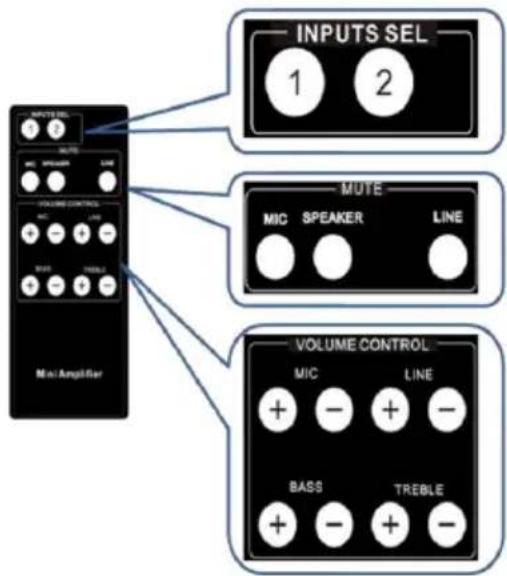
text_image
INPUTS SEL 1 2 MUTE MIC SPEAKER LINE VOLUME CONTROL MIC LINE STRAW TRESLE Mini Amplifier VOLUME CONTROL MIC LINE BASS TREBLE + - + - + - + -Input channel selection:
2x1 selection.
Mute selection:
The user can mute the whole volume out, MIC volume or line volume separately.
Volume/EQ control:
The user can control the level up/down of line volume, Microphone volume, Bass/Treble.
The IR remote is powered by a lithium battery, model name CR2025. (Battery not included). It is 2" wide x 4 ^7/8 " long x 3/8" thick.
IR RECEIVER
The IR receiver is used to receive the IR code from the remote controller. It connects to the AMPMA40X by 3.5mm jack connector, and receives the IR code by the IR sensor. The IR sensor has an adhesive tape at the back that can be stick on the wall or ceiling. The IR receiver is about 4'9" in length (Please see the illustration below).
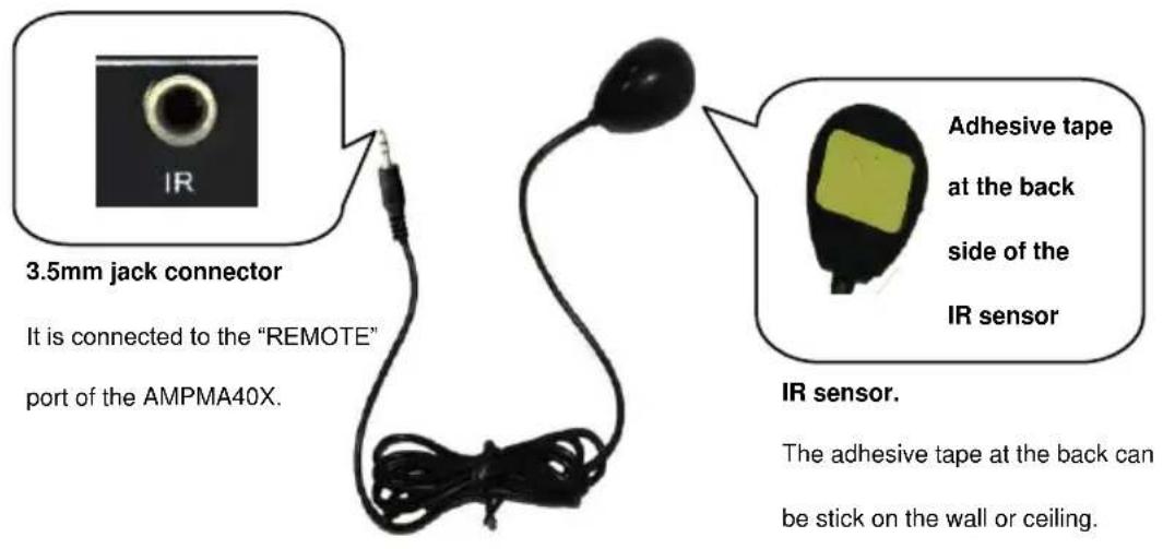
text_image
3.5mm jack connector It is connected to the "REMOTE" port of the AMPMA40X. IR sensor. The adhesive tape at the back can be stick on the wall or ceiling.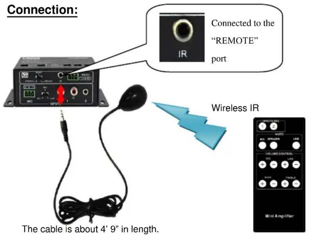
text_image
Connection: Connected to the "REMOTE" port Wireless IR The cable is about 4' 9" in length.Remarks: For any questions or problems, please try to get help from your local distributor, or call OWI at 310-515-1900 or email info@owi-inc.com
WARRANTY
OWI INCORPORATED
17141 Kingsview Ave
Carson, CA 90746
Date Purchased: ____
Model Number: ____
(Keep this part for your record)
CUT AND MAIL

OWI INCORPORATED
17141 Kingsview Ave
Carson, CA 90746
LIMITED THREE YEAR WARRANTY
Model Number:
Model Name:
Serial No.
Date of Purchase: Month: ____ Day ____ Year ____
Owner's Name: ____
Address: ____ City: ____ State ____ Zip____
Dealer's Name: ____ City ____ State ____
Purchased from (please check one):
Video __, Electronic __, Mail Order __, Mass Merchandiser __, Installer __
Others (please specify) ____
Remarks: