AT-OMNI-324 - Audio/video switch Atlona - Free user manual and instructions
Find the device manual for free AT-OMNI-324 Atlona in PDF.

User questions about AT-OMNI-324 Atlona
0 question about this device. Answer the ones you know or ask your own.
Ask a new question about this device
Download the instructions for your Audio/video switch in PDF format for free! Find your manual AT-OMNI-324 - Atlona and take your electronic device back in hand. On this page are published all the documents necessary for the use of your device. AT-OMNI-324 by Atlona.
USER MANUAL AT-OMNI-324 Atlona
Adapter for Peripheral Devices

text_image
PWR HOST LINK SIGNAL OMNISTREAM™ AT-OMNI-324 DC 24V UTILITY PAIRING LANVersion Information
| Version Release Date Notes | ||
| 1 Apr 2018 | Initial release | |
| 2 Oct 2021 | Updated format | |
Sales, Marketing, and Customer Support
Main Office
Atlona Incorporated
70 Daggett Drive
San Jose, CA 95134
United States
Office: +1.877.536.3976 (US Toll-free)
Office: +1.408.962.0515 (US/International)
Sales and Customer Service Hours
Monday - Friday: 6:00 a.m. - 4:30 p.m. (PST)
http://www.atlona.com/
International Headquarters
Atlona International AG
Tödistrasse 18
8002 Zürich
Switzerland
Office: +41 43 508 4321
Sales and Customer Service Hours
Monday - Friday: 09:00 - 17:00 (UTC +1)
Operating Notes

IMPORTANT: Visit http://www.atlona.com/product/AT-OMNI-324 for the latest firmware updates and User Manual.
Atlona, Inc. ("Atlona") Limited Product Warranty
Coverage
Atlona warrants its products will substantially perform to their published specifications and will be free from defects in materials and workmanship under normal use, conditions and service.
Under its Limited Product Warranty, Atlona, at its sole discretion, will either:
- repair or facilitate the repair of defective products within a reasonable period of time, restore products to their proper operating condition and return defective products free of any charge for necessary parts, labor and shipping.
OR
- replace and return, free of charge, any defective products with direct replacement or with similar products deemed by Atlona to perform substantially the same function as the original products.
OR
- refund the pro-rated value based on the remaining term of the warranty period, not to exceed MSRP, in cases where products are beyond repair and/or no direct or substantially similar replacement products exist.
Repair, replacement or refund of Atlona products is the purchaser's exclusive remedy and Atlona liability does not extend to any other damages, incidental, consequential or otherwise.
This Limited Product Warranty extends to the original end-user purchaser of Atlona products and is non-transferrable to any subsequent purchaser(s) or owner(s) of these products.
Coverage Periods
Atlona Limited Product Warranty Period begins on the date of purchase by the end-purchaser. The date contained on the end-purchaser 's sales or delivery receipt is the proof purchase date.
Limited Product Warranty Terms – New Products
• 10 years from proof of purchase date for hardware/electronics products purchased on or after June 1, 2013.
• 3 years from proof of purchase date for hardware/electronics products purchased before June 1, 2013.
• Lifetime Limited Product Warranty for all cable products.
Limited Product Warranty Terms - Refurbished (B-Stock) Products and Discontinued Products
- 3 years from proof of purchase date for all Refurbished (B-Stock) and Discontinued hardware and electronic products purchased on or after June 1, 2013.
Remedy
Atlona recommends that end-purchasers contact their authorized Atlona dealer or reseller from whom they purchased their products. Atlona can also be contacted directly. Visit atlona.com for Atlona's contact information and hours of operation. Atlona requires that a dated sales or delivery receipt from an authorized dealer, reseller or end-purchaser is provided before Atlona extends its warranty services. Additionally, a return merchandise authorization (RMA) and/or case number, is required to be obtained from Atlona in advance of returns.
Atlona requires that products returned are properly packed, preferably in the original carton, for shipping. Cartons not bearing a return authorization or case number will be refused. Atlona, at its sole discretion, reserves the right to reject any products received without advanced authorization. Authorizations can be requested by calling 1-877-536-3976 (US toll free) or 1-408-962-0515 (US/international) or via Atlona's website at atlona.com.
Exclusions
This Limited Product Warranty excludes:
- Damage, deterioration or malfunction caused by any alteration, modification, improper use, neglect, improper packaging or shipping (such claims must be presented to the carrier), lightning, power surges, or other acts of nature.
Atlona, Inc. ("Atlona") Limited Product Warranty
- Damage, deterioration or malfunction resulting from the installation or removal of this product from any installation, any unauthorized tampering with this product, any repairs attempted by anyone unauthorized by Atlona to make such repairs, or any other cause which does not relate directly to a defect in materials and/or workmanship of this product.
- Equipment enclosures, cables, power supplies, batteries, LCD displays, and any accessories used in conjunction with the product(s).
- Products purchased from unauthorized distributors, dealers, resellers, auction websites and similar unauthorized channels of distribution.
Disclaimers
This Limited Product Warranty does not imply that the electronic components contained within Atlona's products will not become obsolete nor does it imply Atlona products or their electronic components will remain compatible with any other current product, technology or any future products or technologies in which Atlona's products may be used in conjunction with. Atlona, at its sole discretion, reserves the right not to extend its warranty offering in instances arising outside its normal course of business including, but not limited to, damage inflicted to its products from acts of god.
Limitation on Liability
The maximum liability of Atlona under this limited product warranty shall not exceed the original Atlona MSRP for its products. To the maximum extent permitted by law, Atlona is not responsible for the direct, special, incidental or consequential damages resulting from any breach of warranty or condition, or under any other legal theory. Some countries, districts or states do not allow the exclusion or limitation of relief, special, incidental, consequential or indirect damages, or the limitation of liability to specified amounts, so the above limitations or exclusions may not apply to you.
Exclusive Remedy
To the maximum extent permitted by law, this limited product warranty and the remedies set forth above are exclusive and in lieu of all other warranties, remedies and conditions, whether oral or written, express or implied. To the maximum extent permitted by law, Atlona specifically disclaims all implied warranties, including, without limitation, warranties of merchantability and fitness for a particular purpose. If Atlona cannot lawfully disclaim or exclude implied warranties under applicable law, then all implied warranties covering its products including warranties of merchantability and fitness for a particular purpose, shall provide to its products under applicable law. If any product to which this limited warranty applies is a “Consumer Product” under the Magnuson-Moss Warranty Act (15 U.S.C.A. §2301, ET SEQ.) or other applicable law, the foregoing disclaimer of implied warranties shall not apply, and all implied warranties on its products, including warranties of merchantability and fitness for the particular purpose, shall apply as provided under applicable law.
Other Conditions
Atlona's Limited Product Warranty offering gives legal rights, and other rights may apply and vary from country to country or state to state. This limited warranty is void if (i) the label bearing the serial number of products have been removed or defaced, (ii) products are not purchased from an authorized Atlona dealer or reseller. A comprehensive list of Atlona's authorized distributors, dealers and resellers can be found at www.atlona.com.
Important Safety Information
CAUTION
RISK OF ELECTRIC SHOCK
DO NOT OPEN
CAUTION: TO REDUCT THE RISK OF
ELECTRIC SHOCK
DO NOT OPEN ENCLOSURE OR EXPOSE
TO RAIN OR MOISTURE.
NO USER-SERVICEABLE PARTS
INSIDE REFER SERVICING TO
QUALIFIED SERVICE PERSONNEL.

The exclamation point within an equilateral triangle is intended to alert the user to the presence of important operating and maintenance instructions in the literature accompanying the product.

The information bubble is intended to alert the user to helpful or optional operational instructions in the literature accompanying the product.
- Read these instructions.
- Keep these instructions.
- Heed all warnings.
- Follow all instructions.
- Do not use this product near water.
- Clean only with a dry cloth.
- Do not block any ventilation openings. Install in accordance with the manufacturer's instructions.
-
Do not install or place this product near any heat sources such as radiators, heat registers, stoves, or other apparatus (including amplifiers) that produce heat.
-
Do not defeat the safety purpose of a polarized or grounding-type plug. A polarized plug has two blades with one wider than the other. A grounding type plug has two blades and a third grounding prong. The wide blade or the third prong are provided for your safety. If the provided plug does not fit into your outlet, consult an electrician for replacement of the obsolete outlet.
- Protect the power cord from being walked on or pinched particularly at plugs, convenience receptacles, and the point where they exit from the product.
- Only use attachments/accessories specified by Atlona.
- To reduce the risk of electric shock and/or damage to this product, never handle or touch this unit or power cord if your hands are wet or damp. Do not expose this product to rain or moisture.
- Unplug this product during lightning storms or when unused for long periods of time.
- Refer all servicing to qualified service personnel. Servicing is required when the product has been damaged in any way, such as power-supply cord or plug is damaged, liquid has been spilled or objects have fallen into the product, the product has been exposed to rain or moisture, does not operate normally, or has been dropped.


FCC Compliance
FCC Compliance and Advisory Statement: This hardware device complies with Part 15 of the FCC rules. Operation is subject to the following two conditions: 1) this device may not cause harmful interference, and 2) this device must accept any interference received including interference that may cause undesired operation. This equipment has been tested and found to comply with the limits for a Class A digital device, pursuant to Part 15 of the FCC Rules. These limits are designed to provide reasonable protection against harmful interference in a commercial installation. This equipment generates, uses, and can radiate radio frequency energy and, if not installed or used in accordance with the instructions, may cause harmful interference to radio communications. However there is no guarantee that interference will not occur in a particular installation. If this equipment does cause harmful interference to radio or television reception, which can be determined by turning the equipment off and on, the user is encouraged to try to correct the interference by one or more of the following measures: 1) reorient or relocate the receiving antenna; 2) increase the separation between the equipment and the receiver; 3) connect the equipment to an outlet on a circuit different from that to which the receiver is connected; 4) consult the dealer or an experienced radio/TV technician for help. Any changes or modifications not expressly approved by the party responsible for compliance could void the user's authority to operate the equipment. Where shielded interface cables have been provided with the product or specified additional components or accessories elsewhere defined to be used with the installation of the product, they must be used in order to ensure compliance with FCC regulations.
Copyright, Trademark, and Registration
© 2021 Atlona Inc. All rights reserved. "Atlona" and the Atlona logo are registered trademarks of Atlona Inc. Pricing, specifications and availability subject to change without notice. Actual products, product images, and online product images may vary from images shown here.
All other trademark(s), copyright(s), and registered technologies mentioned in this document are the properties of their respective owner(s).
Table of Contents
Introduction 8
Features 8
Package Contents 8
Panel Description 9
Installation 10
Connection Instructions 10
Over a Network 10 Direct Connection 10
Connection Diagrams 11
Basic Operation 12 LED Indicators 12 Pairing 13
Using AMS 13 Manual Pairing 16 Unpairing an Extender 16 Using Velocity™ 17
DHCP Reset 25
The AMS Interface 26 Device Info tab 26 Network tab 27 Pairing tab 28
Appendix 29 Mounting Instructions 29 Supported Cameras 30 Specifications 31
Introduction
The Atlona OmniStream™ 324 (AT-OMNI-324) works in tandem with the OmniStream 311 (AT-OMNI-311) for extending USB from peripheral devices to a PC over Gigabit Ethernet. The OmniStream 324 features a four-port USB hub for peripherals, while the OmniStream 311 interfaces with a PC or other host device. The OmniStream USB over IP system is compatible with USB 2.0 data rates of up to 480 Mbps. It can be used with high-bandwidth devices including cameras, speakerphones, microphones, and DSPs, plus standard USB HID class devices such as a keyboard, mouse, or touch display. Up to seven OmniStream 324 units can be simultaneously paired to an OmniStream 311. Additionally, USB routing over the network can be managed using Atlona Management System (AMS) 2.0.
OmniStream USB products can be used in a wide variety of system design scenarios for soft codec conferencing and remote keyboard / mouse control. They are ideal for integrating USB audio and video devices as part of a fully IP-based meeting room system, in conjunction with OmniStream AV over IP devices and the Velocity Control System.
Features
- Extend USB over Gigabit Ethernet using CAT5e/6 cable.
• Four-port USB hub.
• Supports high bandwidth devices such as webcams and speakers, as well as standard HID-class peripherals.
• Compatible with USB 2.0 data rates up to 480 Mbps. - Ideal for meeting room applications to extend USB from touch displays, cameras, speakerphones, DSPs, and more.
• Design flexible and scalable AV systems in combination with OmniStream AV encoders and decoders. - Up to seven OmniStream 324 units can be paired with an OmniStream 311 over a network.
• USB signal routing configured and managed by AMS (Atlona Management System) 2.0. - Ready for integration with Atlona Velocity™ Control System to manage USB signal routing.
• Front panel LED indicators for power, network and USB host connectivity, and USB signal presence over IP. - Low-profile, 1 inch (25 mm) high enclosure.
- Includes installation guide, surface-mounting brackets, and external universal power supply.
Package Contents
1 x AT-OMNI-324
2 x Mounting brackets
1 x 24 V DC power supply
1 x Installation Guide
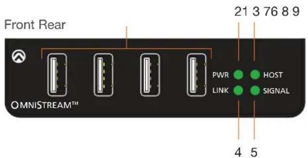
Panel Description
text_image
Front Rear 21 3 76 8 9 PWR ● HOST LINK ● SIGNAL 4 5 OMNISTREAM™
text_image
DC 24V UTILITY PAIRING LAN AT-OMNI-3241 USB Device Ports
Connect up to four USB devices using these ports.
2 PWR
This LED indicator glows solid green when the unit is powered.
3 HOST
This LED indicator glows green when a USB host device is connected to the AT-OMNI-311 (not included). Refer to LED Indicators (page 12) for more information.
4 LINK
This LED indicator is solid green when a solid connection between this unit and the transmitter has been established. Refer to LED Indicators (page 12) for more information.
5 SIGNAL
This LED indicator monitors data transmission between this unit and the receiver. The LED will blink intermittently whether or not a USB device is connected. Refer to LED Indicators (page 12) for more information.
6 DC 24V
Connect the included power supply to this power receptacle.
7 UTILITY
This port is for factory programming.
8 PAIRING
Press this button to begin the pairing process.
9 LAN
Connect an Ethernet cable from this port to the Local Area Network (LAN).
Installation
Connection Instructions

IMPORTANT: The AT-OMNI-324 supports a maximum of 3 additional USB hubs that may be connected downstream. Up to 7 AT-OMNI-324 units may be paired to an AT-OMNI-311, allowing up to a maximum of 31 USB devices.
- Place the AT-OMNI-324 near the location of the USB devices to be connected. Connect up to four USB devices to the USB ports on the AT-OMNI-324.
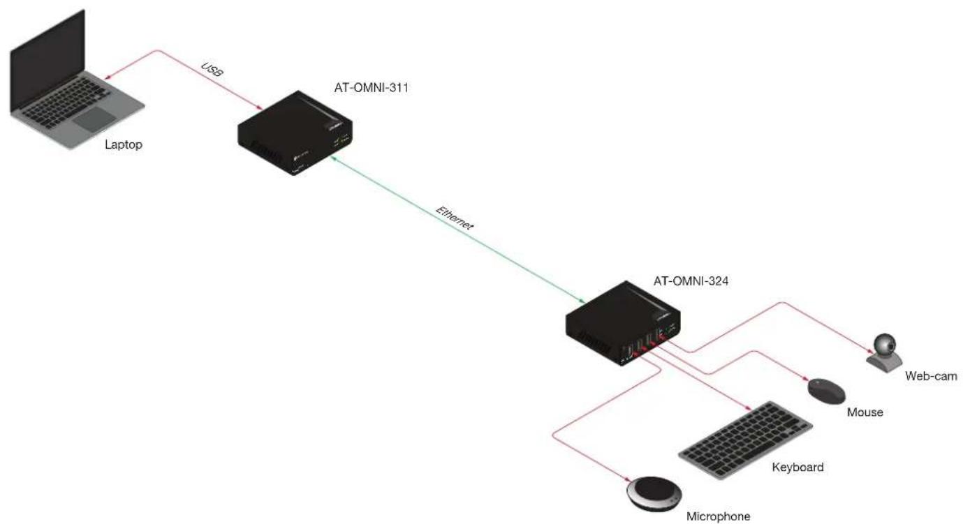
The AT-OMNI-324 can be connected to a AT-OMNI-311 (not included) in one of two ways:
Over a Network
a. Connect an Ethernet cable, up to 330 feet (100 meters), from the LAN port on the AT-OMNI-324 to the network switch. Note that multiple AT-OMNI-324 units can be connected to the network.
b. Connect an Ethernet cable, up to 330 feet (100 meters), from the transmitter (AT-OMNI-311; not included) to a switch on the same network.

NOTE: When connecting a transmitter and receiver, over a network, the cable distance between hops must not exceed 330 feet (100 meters) for copper connections (fiber extenders can be used to create longer runs). For example, connecting up to five network switches, using copper cabling, can be used to extend USB up to 1980 feet (600 meters).
Direct Connection
a. Connect an Ethernet cable, up to 330 feet (100 meters), from the LAN port of the AT-OMNI-324 directly to the AT-OMNI-311 (not included).
- Connect the included power supply to the DC 24V power receptacle.
- Connect the power supply to an available electrical outlet.
- Refer to Pairing (page 13) for instructions on pairing.
Connection Diagrams
Connection over a Local Area Network (LAN)

flowchart
graph TD
    A["Laptop"] -->|USB| B["AT-OMNI-311"]
    B -->|Ethernet| C["Network Switch"]
    C -->|Ethernet| D["Network Switch"]
    D -->|Ethernet| E["AT-OMNI-324"]
    E --> F["Microphone"]
    F --> G["Keyboard"]
    G --> H["Web-cam"]
    E --> I["Mouse"]
    E --> J["LAN"]
Direct Connection
flowchart
graph TD
    A["Laptop"] -->|USB| B["AT-OMNI-311"]
    B -->|Ethernet| C["AT-OMNI-324"]
    C --> D["Microphone"]
    C --> E["Keyboard"]
    C --> F["Mouse"]
    C --> G["Web-cam"]
Basic Operation
LED Indicators
The PWR, LINK, HOST, and SIGNAL LED indicators on the OmniStream 324 provide basic information on the current status of the unit.
| LED Description | ||
| PWR Solid green Unit is powered. | ||
| Off Unit is not powered. | Verify that the included power supply is connected to the AT-OMNI-324 and the power supply are connected to a live electrical outlet. | |
| LINK Solid green The link integrity between the receiver and the transmitter is good. | ||
Blinking green  (slow) (slow) | The receiver is attempting to establish a link to the transmitter. | |
Blinking green  (fast) (fast) | The receiver is in Pairing Mode. | |
| Off There is no link between the receiver and the transmitter.Direct Mode:Verify that an Ethernet cable is connected between the LAN port on the receiver and the transmitter.Network Mode:Verify that an Ethernet cable is connected between the LAN port on the receiver and the network switch.Check that the Ethernet cable is not physically damaged.Make sure that the Ethernet cable does not exceed 330 feet (100 meters). | ||
| HOST Solid green The transmitter is properly enumerated on the host computer. | ||
| Blinking green The transmitter is in a suspended state. | ||
| SIGNAL | Blinking green | This LED indicator will blink intermittently when data is being transmitted between the receiver and the transmitter. |
| Off The receiver is in Suspend Mode. | ||
Pairing
Pairing an OmniStream 324 to an OmniStream 311 (not incuded) is managed using the Atlona Management System (AMS). AMS is free and can be downloaded from https://atlona.com/AMS. The pairing process can also be performed using the Server Appliance for Atalona Management System (AT-AMS-HW).
Using AMS
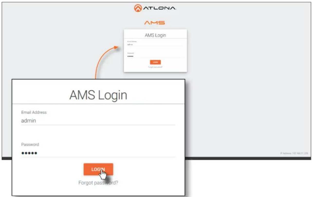
- Launch a web browser and enter the IP address of AMS, in the address bar.
- Enter the required login credentials.
text_image
ATLONA AMS AMS Login Email Address: admin Password ••••••• LOGIN Forgot password? AMS Login Email Address: admin Password ••••••• Forgot password?- Click the Login button.
- The AMS Dashboard will be displayed.
- Click the ≡icon, in the upper-left corner of the AMS Dashboard.
- Click Devices > Unassigned from the fly-out menu.
All available OmniStream 324 devices will be displayed under the Unassigned category. When a device is unassigned, it means that the device has not yet been assigned to a site, building, and/or room. Refer to the AMS User Manual for more information on these topics.
- Click the AT-OMNI-324 from the Unassigned list.

text_image
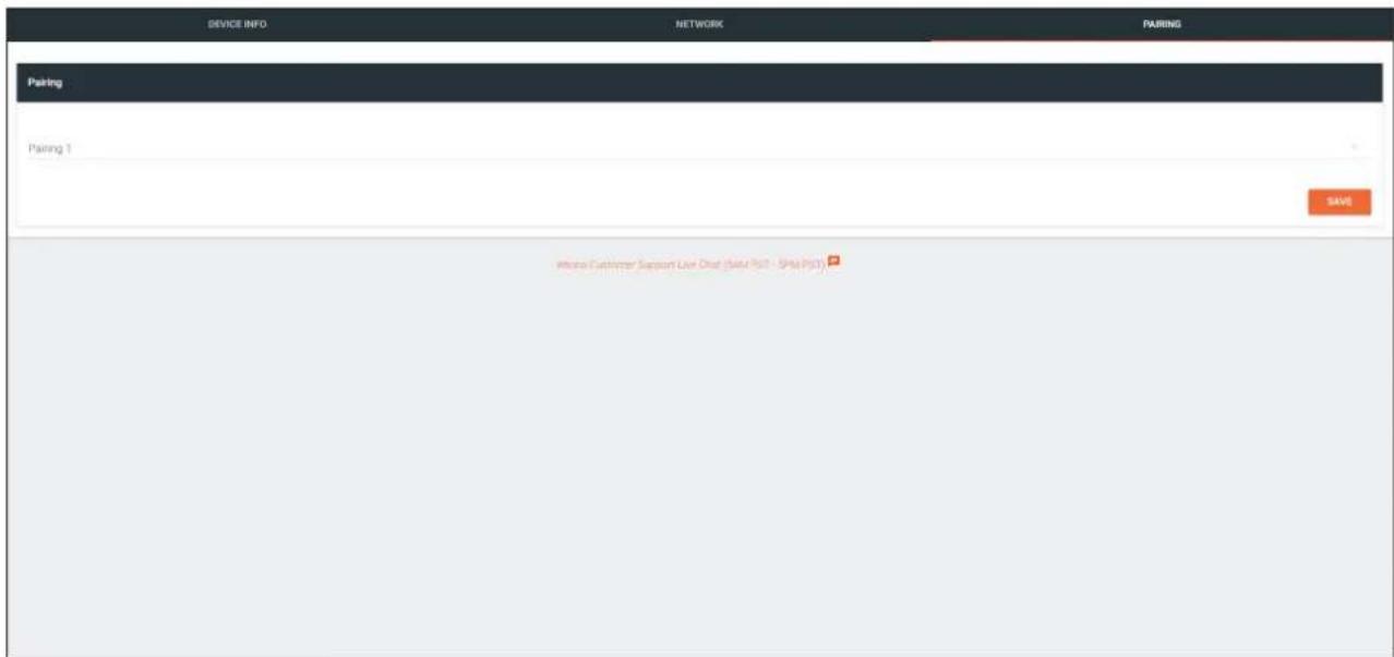
AMS Device List Name Model P Site Building Roads AT-OMNI-311: 00:1b:13:02:92.8a AT-UHD-CLSO-824 AT-JUNO-451 AT-OMNI-324: 00:1b:13:02:61.e0 AT-OMNI-512 AT-OMNI-311: 00:1b:13:02:92.8a AT-UHD-CLSO-824 AT-UHD-CLSO-824 102.108.11.29 Not Assigned Not Assigned AT-UHD-CLSO-824 AT-UHD-CLSO-824 102.108.11.29 Not Assigned Not Assigned AT-UHD-CLSO-824 AT-UHD-CLSO-824 102.108.11.29 Not Assigned Not Assigned AT-UHD-CLSO-824 AT-UHD-PROZ-00A 102.108.11.29 Not Assigned Not Assigned At UHD-CLSO-824 AT-UHD-PROZ-00A 102.108.11.29 Not Assigned Not Assigned At UHD-CLSO-824 AT-UHD-PROZ-00A 102.108.11.29 Not Assigned Not Assigned At UHD-CLSO-824 AT-UHD-PROZ 00A 102.108.11.29 Not Assigned Not Assigned At UHD-CLSO-824 AT-UHD-PROZ 00A 102.108.11.29 Not Assigned Not Assigned At UHD-CLSO-824 AT-UHD-PROZ 00A 102.108.11.30 Not Assigned Not Assigned At UHD-CLSO-824 AT-UHD-PROZ 00A 102.108.11.30 Not Assigned Not Assigned At UHD-CLSO-824 AT-UHD-PROZ 00A 102.108.11.30 Not Assigned Not Assigned At UHD-CLSO-854 AT-UHD-CLSO-854 102.108.11.30 Not Assigned Not Assigned At UHD-CLSO-854 AT-UHD-CLSO-854 102.108.11.30 Not Assigned Not Assigned At UHD-CLSO-854 AT-UHD-CLSO-854 102.108.11.30 No Assigned No Assigned At UHD-CLSO-854 AT-UHD-CLSO-854 102.108.11.30 No Assigned No Assigned At UHD-CLSO-854 AT-UHD-CLSO-854 102.108.11.30 No Assigned No Assigned At UHD-CLSO-854 AT-UHO-CLSO-854 102.108.11.30 No Assigned No Assigned At UHD-CLSO-854 AT-UHO-CLSO-854 102.108.11.30 No Assigned No Assigned At UHD-CLSO-854 AT-UHO-CLSO-854 102.108 11:37 At UHD-CLSO-854 AT-UHO-CLSO-854 102.108 11:37 At UHD-CLSO-854 AT-UHO-CLSO-854 102.108 11:37 At UHD-CLSO-854 AT-UHO-CLSO-854 102. 103 97 At UHD-CLSO-854 AT-UHO-CLSO-854 102. 103 97 At UHD-CLOD 666 AT-UHO-CLOD 666 Not Assigned Nat Assigned At UHD-CLOD 666 AT-UHO-CLOD 666 Not Assigned Nat Assigned At UHD-CLOD 666 AT-UHO-CLOD 666 Not Assigned Nat Assigned At UHD-CLOD 666 AT-UHO-CLOD 666 Not Assigned Nat Assigned At UHD-CLOD 666 AT-UHO-DIOZ 666 Not Assigned Nat Assigned At UHD-CLOD 666 AT-UHO-DIOZ 666 Not Assigned Nat Assigned At UHD-CLOD 666 AT-UHO-DIOZ 666 Not Assigned Nat Assigned At UHD-CLOD 666 AT-UHO-DIOZ 666 Not Assigned Nat Assigned At UHD-CLSO 777 AT-UHO-DLSO 777 Not Assigned Nat Assigned At UHD-CLSO 777 AT-UHO-DLSO 777 Not Assigned Nat Assigned At UHD-CLSO 777 AT-UHO-DLSO 777 Not Assigned Nat Assigned At UHD-CLSO 777 AT-UHO-DLSO 777 Not Assigned Nat Assigned At UHD-CLSO 783 AT-UHO-DLSO 783 Not Assigned Nat Assigned At UHD-CLSO 783 AT-UHO-DLSO 783 Not Assigned Nat Assigned At UHD-CLSO 783 AT-UHO-DLSO 783 Not Assigned Nat Assigned At UHD-CLSO 783 AT-UHO-DLSO 783 Not Assigned Nat Assigned- The DEVICE INFO page for the AT-OMNI-324 will be displayed. Click the PAIRING tab.
text_image
DEVICE INFO NETWORK PARING Pairing Pairing 1 SAVE Where Customer Support Live Chat (Said PSY - Split PSY)Basic Operation
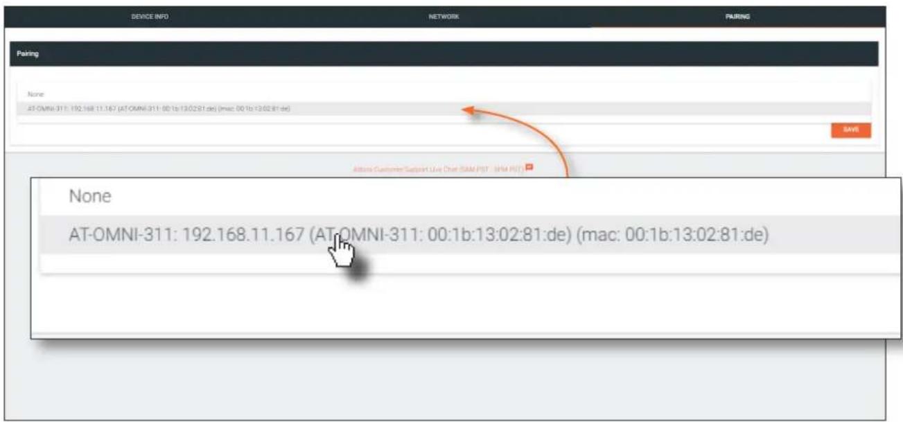
- Click the Pairing drop-down list and select the desired OmniStream 311. In this example, only a single OmniStream 311 is connected to the network. Therefore, this is the only available option. Up to seven OmniStream 324 units can be paired to an OmniStream 311.
text_image
DEVICE INFO NETWORK PAIRING Pairing None AT-OMNI-311: 192.168.11.167 (AT-OMNI-311: 00:1b:13:02:81:de) (mac: 00:1b:13:02:81:de) SAMS Address Customer Support Live Chat (SAM PST - SPM PST) None AT-OMNI-311: 192.168.11.167 (AT-OMNI-311: 00:1b:13:02:81:de) (mac: 00:1b:13:02:81:de)- Click the SAVE button at the bottom of the page.
- The pairing process is complete. Repeat steps 7 through 10 for each OmniStream 324 on the network.
To unpair an OmniStream 324 from an OmniStream 311, select None from the drop-down list and then click the SAVE button.
Basic Operation
Manual Pairing
The OmniStream 311 and OmniStream 324 can also be paired manually. This applies when the OmniStream 311 and OmniStream 324 are connected, either through a network switch (on the same broadcast domain) or directly to one another using category cable. This instructions below cover manual pairing for both the OmniStream 311 and OmniStream 324.
- Make sure both the OmniStream 311 and OmniStream 324 are connected, either directly or through a network switch, and that all USB connections have been made.
OmniStream 311
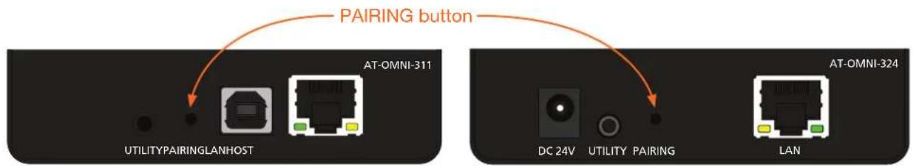
- Press and hold the PAIRING button, for no more than 10 seconds, on the OmniStream 311 using the end of a paperclip or other pointed object.

IMPORTANT: Pressing the PAIRING button for more than 10 seconds will cancel the pairing mode.
text_image
PAIRING button AT-OMNI-311 UTILITYPAIRINGLANHOST DC 24V UTILITY PAIRING LAN AT-OMNI-324- Release the PAIRING button. The LINK LED indicator will begin flashing. Pairing mode is now active on the OmniStream 311.

NOTE: To cancel pairing mode, press and hold the PAIRING button for more than 10 seconds.
OmniStream 324
- Press and hold the PAIRING button on the OmniStream 324, for no more than 10 seconds, using the end of a paperclip or other pointed object.

IMPORTANT: Pressing the PAIRING button for more than 10 seconds will cancel the pairing mode.
The PAIRING button on the OmniStream 324 must be pressed within 10 minutes of activating pairing mode on the OmniStream 311. If not, then the pairing process will automatically be cancelled.
- Release the PAIRING button. The LINK LED indicator will begin flashing. Pairing mode is now active on the OmniStream 324.
The OmniStream 311 and OmniStream 324 will begin the linking process. During the linking process, the LINK LED indicator on both unit may flash more slowly. This is normal behavior.
Once both LINK LED indicators are solid green, the pairing process will be complete.
Unpairing an Extender
To unpair one extender from the other, press and hold the PAIRING button, on either of the connected units, for more than 10 seconds, then release.
Basic Operation
Using Velocity™
The following section provides instructions on pairing AT-OMNI-311 units with AT-OMNI-324 units using the Atlona Velocity Control Software. Familiarity with the Velocity software is assumed. Refer to the Atlona Velocity User Manual for more information, if necessary.
- Launch a web browser and enter the IP address of Velocity, in the address bar.
- Enter the required login credentials.
- Click the Login button.
- The Velocity Dashboard will be displayed.
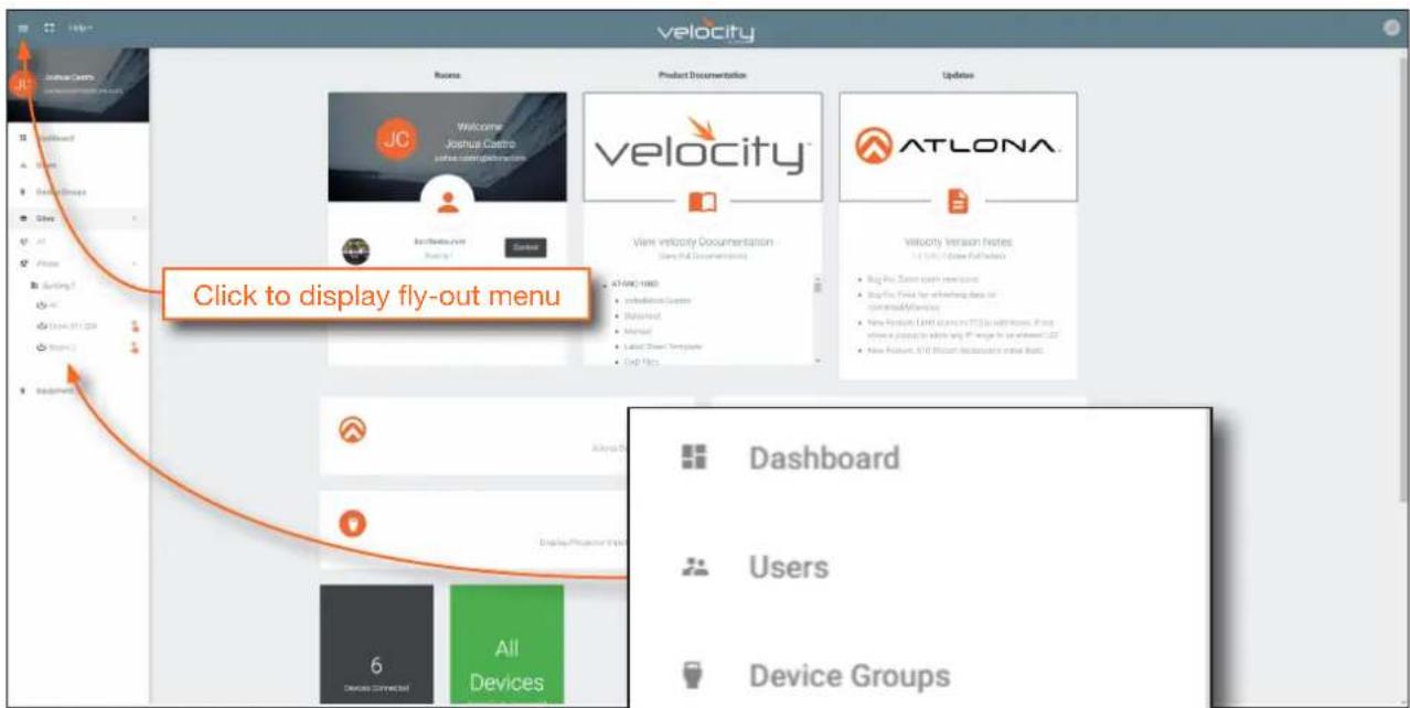
- Click the ≡icon, in the upper-left corner, to display the fly-out menu.
text_image
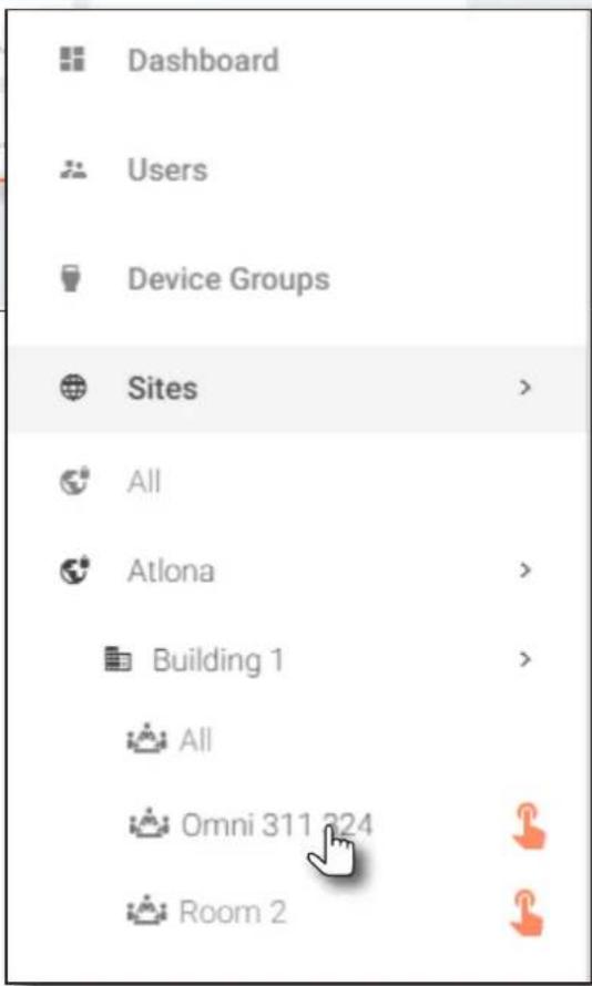
velocity Welcome Joshua Camo vinoa.com/epinformation Product Documentation velocity ATLONA Click to display fly-out menu Dashboard Users Device Groups- Click Sites in the menu bar to expand the list of buildings and rooms.
- Click the desired room from the list.
In the example on the right, a set of units have been set up in a room called Omni 311 324 within Building 1.
Refer to the Velocity User Manual for instructions on creating rooms and adding devices to rooms.
text_image
Dashboard Users Device Groups Sites > All Atlona > Building 1 > All Omni 311 324 Room 2 >Basic Operation
- The Modify Room screen will be displayed. Click the Room Control Options icon, in the upper-right corner of the Technology bar.
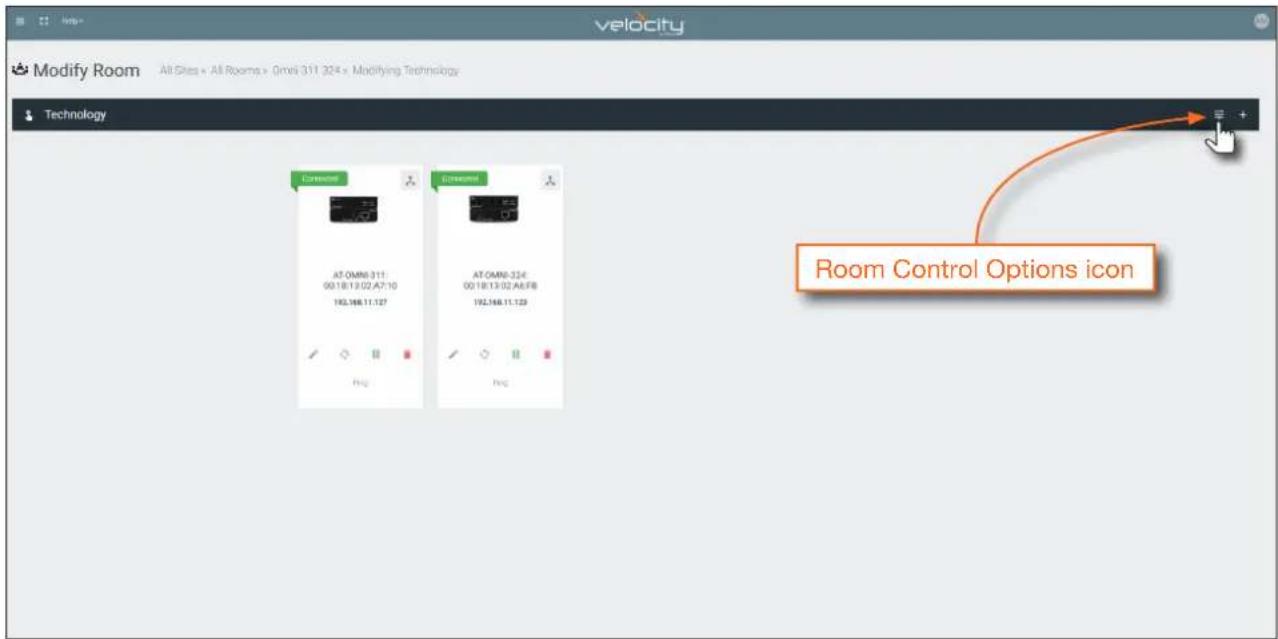
text_image
Modify Room All Sites = All Rooms = Omni 311 324 x Modifying Technology Technology AT:OMN-311: 00:18:13:02 A7:10 192.168.11.127 AT:OMN-324: 00:18:13:02 A6:FB 192.168.11.128 Room Control Options icon- The Room Control Options screen will be displayed. In order to allow units to be paired or unpaired, two macros will need be created: one for pairing and one for unpairing.
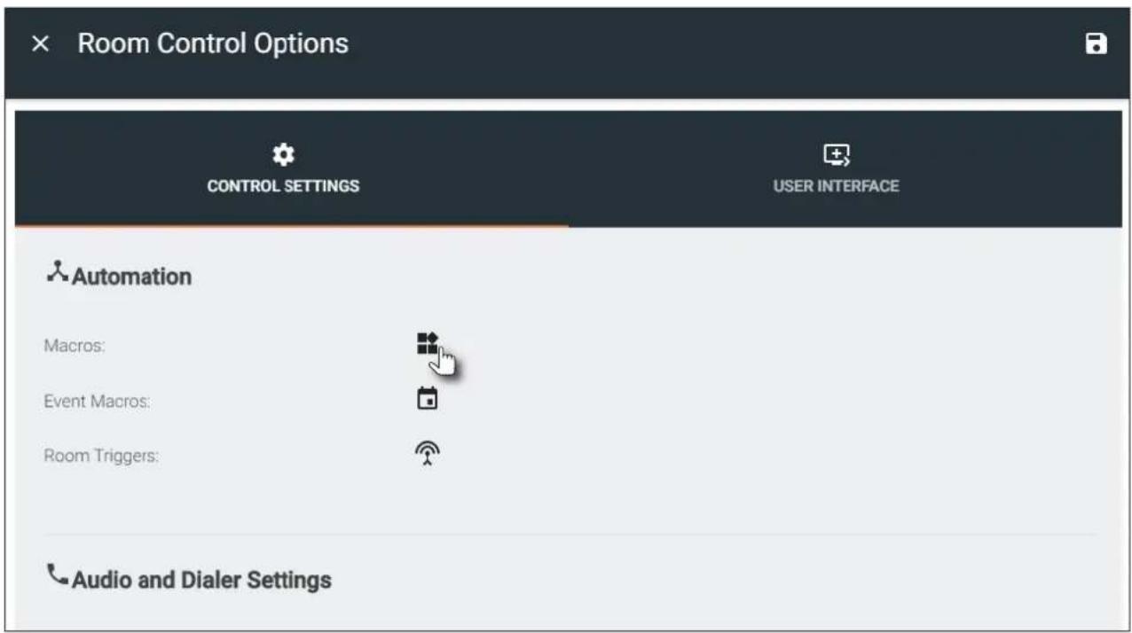
text_image
Room Control Options CONTROL SETTINGS USER INTERFACE Automation Macros: Event Macros: Room Triggers: Audio and Dialer Settings- Click the Macros icon to display the Room Macros screen.
Creating the Unpair Macro
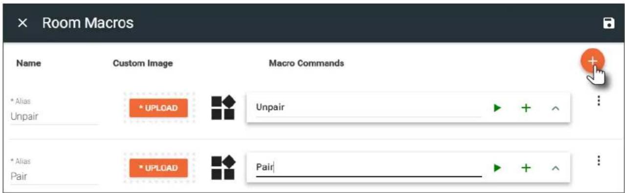
- In the Room Macros screen, click the + icon, in the upper-right corner of the screen.

text_image
Room Macros Name Custom Image Macro Commands- Enter the name of the macro in both the Name and Macro Commands text field. The name of the macro should be descriptive of what option is being performed.
- Click the + icon to display the macro configuration dialog.

text_image
Macro Configuration icon Name Custom Image * Alias Unpair * UPLCAD Unpair| + ^ ...- Click the Device drop-down list and select one of the device from this list. Since the "Unpair" macro will disconnect the two units from one another, either the AT-OMNI-311 or AT-OMNI-324 can be selected from this drop-down list. In this example, the AT-OMNI-324 is selected.
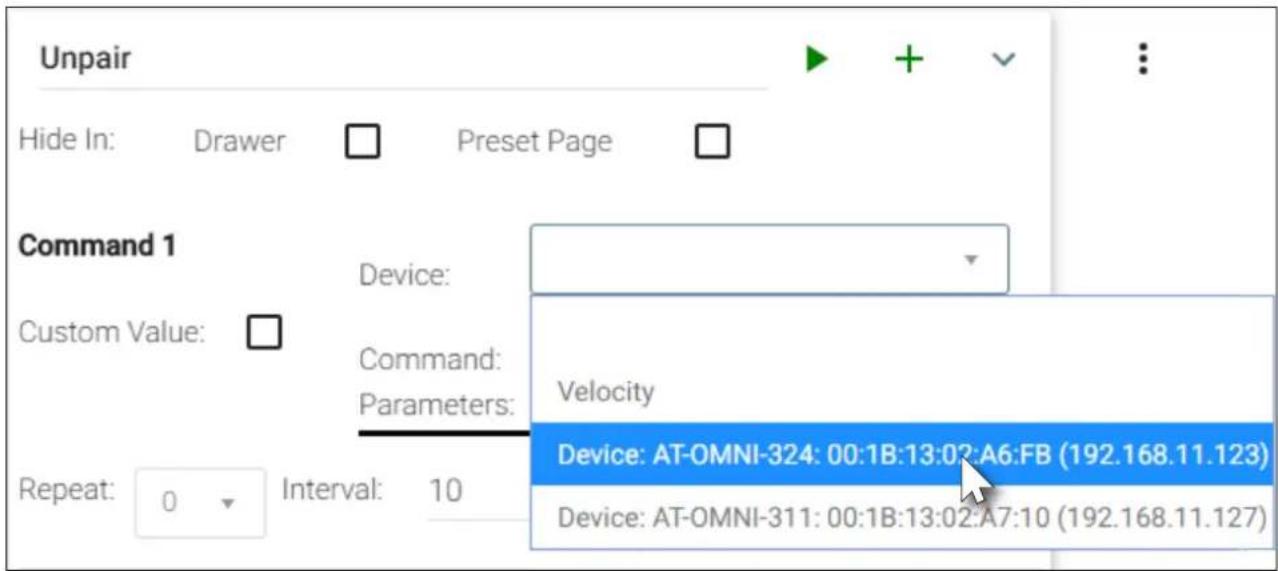
text_image
Unpair Hide In: Drawer Preset Page Command 1 Device: Custom Value: Command: Parameters: Velocity Repeat: 0 Interval: 10 Device: AT-OMNI-324: 00:1B:13:02:A6:FB (192.168.11.123) Device: AT-OMNI-311: 00:1B:13:02:A7:10 (192.168.11.127)- Click the Command drop-down list and select Remove All Pairings.
- Repeat steps 3 through 5: when repeating theses steps, select the AT-OMNI-311 from the Device drop-down list.
- Click the Save icon in the top-right portion of the Room Macros bar.
Creating the Pair Macro
- In the Room Macros screen, click the + icon, in the upper-right corner of the screen.
text_image
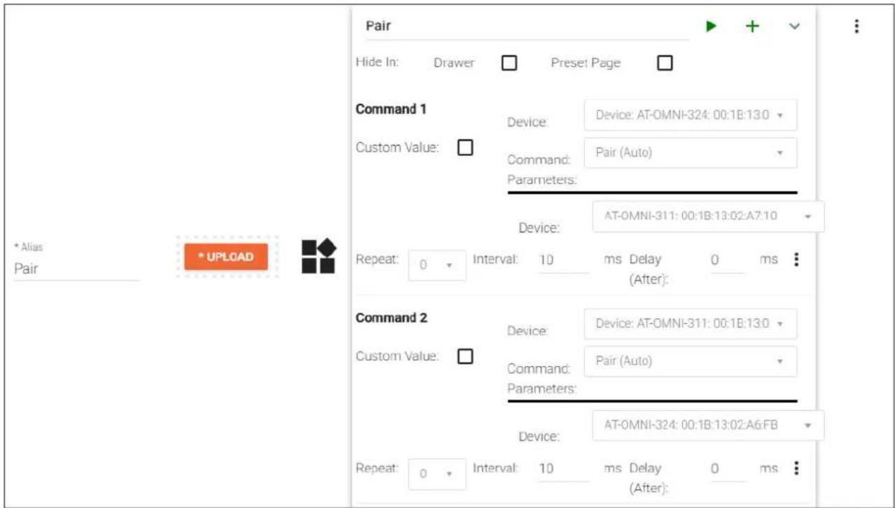
Room Macros Name Custom Image Macro Commands * Alias * UPLOAD Unpair Unpair * Alias * UPLOAD Pair- Enter the name of the macro in both the Name and Macro Commands text field. In this example, "Pair" will be used.
- Click the + icon to display the macro configuration dialog.
- Click the Device drop-down list and select the AT-OMNI-324.
- Click the Command drop-down list and select Pair (Auto).
- Click the second Device drop-down list and select the unit to be paired. Since the AT-OMNI-324 was already selected, select the AT-OMNI-311 from the drop-down list.
text_image
Pair Hide In: Drawer Preset Page Command 1 Device: Device: AT-OMNI-324: 00:1B:13.0 Custom Value: □ Command: Pair (Auto) Parameters: Device: AT-OMNI-311: 00:1B:13:02:A7:10 Repeat: 0 Interval: 10 ms Delay 0 ms (After): Command 2 Device: Device: AT-OMNI-311: 00:1B:13.0 Custom Value: □ Command: Pair (Auto) Parameters: Device: AT-OMNI-324: 00:1B:13:02:A6:FB Repeat: 0 Interval: 10 ms Delay 0 ms (After):- Repeat steps 2 through 5: For the first Device drop-down list, select the AT-OMNI-324, and for the second Device drop-down list, select the AT-OMNI-311. When this macro is completed, it should appear similar to the following:
- Click the Save icon, in the top-right portion of the Room Macros bar.
Pairing and Unpairing Units

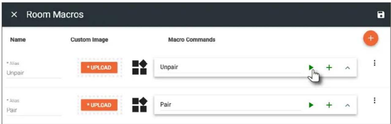
IMPORTANT: Before pairing units, make sure to unpair (remove) any existing pairings using the "unpair" macro that was created on page 19.
- Click the ▶ icon for the "Unpair" macro. This will remove any possible "out-of-the-box" (factory) pairing that may exist.
- Click the ▶ icon for the "Pair" macro to pair the two units.
text_image
Room Macros Name Custom Image Macro Commands * Alias * UPLOAD Unpair Unpair * Alias * UPLOAD PairExample: Pairing two AT-OMNI-324 to a single AT-OMNI-311
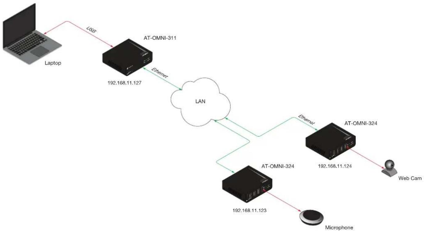
The following illustration depicts an example of how to pair two AT-OMNI-324 units to a single AT-OMNI-311. Refer to the instructions on the following page for how to configure this setup. Note that arbitrary IP addresses have been assigned for reference.
flowchart
graph TD
    A["Laptop"] -->|USB| B["AT-OMNI-311"]
    B -->|Ethernet| C["LAN"]
    C --> D["AT-OMNI-324"]
    D -->|Ethernet| E["AT-OMNI-324"]
    E --> F["Microphone"]
    F --> G["Web Cam"]
    B -->|192.168.11.127| B
    D -->|192.168.11.123| D
Basic Operation
- In the Room Macros screen, click the + icon, in the upper-right corner of the screen.
- Enter "Unpair" for both the Name and Macro Commands text field.
- Click the + icon to display the macro configuration dialog.
- Click the Device drop-down list and select one of the devices from this list. Since the "Unpair" macro will be disconnecting a total of three units from one another, the "Unpair" macro will contain a total of three commands. In this example, the AT-OMNI-324 is arbitrarily selected.

text_image
Command 1 Device: Custom Value: Command: Parameters: Repeat: 0 Interval: 10 Velocity Device: AT-OMNI-324: 00:1B:13:02:A6:FB (192.168.11.123) Device: AT-OMNI-324: 00:1B:13:02:A7:07 (192.168.11.124) Device: AT-OMNI-311: 00:1B:13:02:A7:10 (192.168.11.127)- Click the Command drop-down list and select Remove All Pairings.
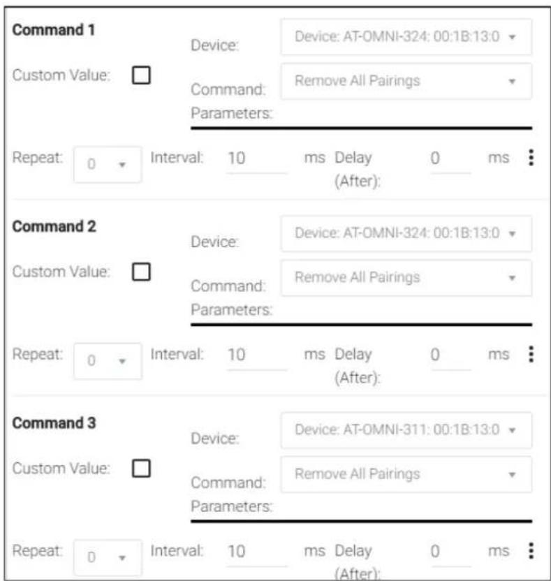
- Repeat steps 3 through 5, selecting the second AT-OMNI-324 and then the AT-OMNI-311 from the Device dropdown list. When completed, the "Unpair" macro should appear as follows:
text_image
Command 1 Device: Device: AT-OMNI-324: 00:1B:13:0 Custom Value: □ Command: Remove All Pairings Parameters: Repeat: 0 ▼ Interval: 10 ms Delay 0 ms (After): Command 2 Device: Device: AT-OMNI-324: 00:1B:13:0 Custom Value: □ Command: Remove All Pairings Parameters: Repeat: 0 ▼ Interval: 10 ms Delay 0 ms (After): Command 3 Device: Device: AT-OMNI-311: 00:1B:13:0 Custom Value: □ Command: Remove All Pairings Parameters: Repeat: 0 ▼ Interval: 10 ms Delay 0 ms (After):- Click the Save icon in the top-right portion of the Room Macros bar.
- Create a "pairing" macro by clicking the + icon, in the upper-right corner of the screen.
Note that since there are two AT-OMNI-324 units, creating the "Pair" macro can be achieved using two different methods:
a. Create two separate macros: one to pair the AT-OMNI-311 and the AT-OMNI-324 with the camera, and another one to pair the AT-OMNI-311 with the AT-OMNI-324 with the speakerphone. This method provides more control, providing the option of which AT-OMNI-324 is paired with the AT-OMNI-311.
b. Create a single macro which pairs both AT-OMNI-324 units to the AT-OMNI-311. This method is more convenient, but does not provide the option of which AT-OMNI-324 is paired with the AT-OMNI-311.
For this example, two separate pairing macros will be created:
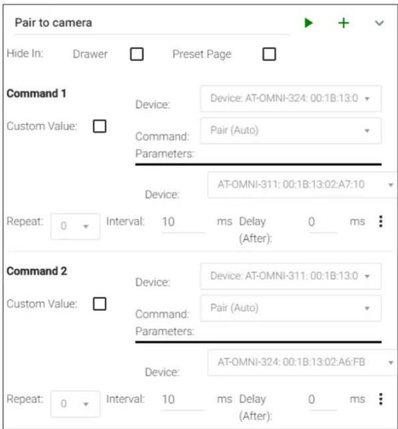
- Enter "Pair to camera" in both the Name and Macro Commands text field. This macro will be used to pair the computer with the camera.
- Click the + icon to display the macro configuration dialog.
- Click the Device drop-down list and select the AT-OMNI-324 that is connected to the camera. In this example, the AT-OMNI-324 with the IP address of 192.168.11.124 will be selected.
- Click the Command drop-down list and select Pair (Auto).
- Click the second Device drop-down list and select the AT-OMNI-311.
- Repeat steps 10 through 13: select the AT-OMNI-311 in the first Device drop-down list, and then the AT-OMNI-324 with the camera, from the second Device drop-down list. The "Pair to camera" macro should now appear as follows:
text_image
Pair to camera Hide In: Drawer Preset Page Command 1 Device: Device: AT-OMNI-324: 00:1B:13:0 Custom Value: □ Command: Pair (Auto) Parameters: Device: AT-OMNI-311: 00:1B:13:02:A7:10 Repeat: 0 Interval: 10 ms Delay 0 ms : (After): Command 2 Device: Device: AT-OMNI-311: 00:1B:13:0 Custom Value: □ Command: Pair (Auto) Parameters: Device: AT-OMNI-324: 00:1B:13:02:A6:FB Repeat: 0 Interval: 10 ms Delay 0 ms : (After):Basic Operation
- Click the Save icon in the top-right portion of the Room Macros bar.
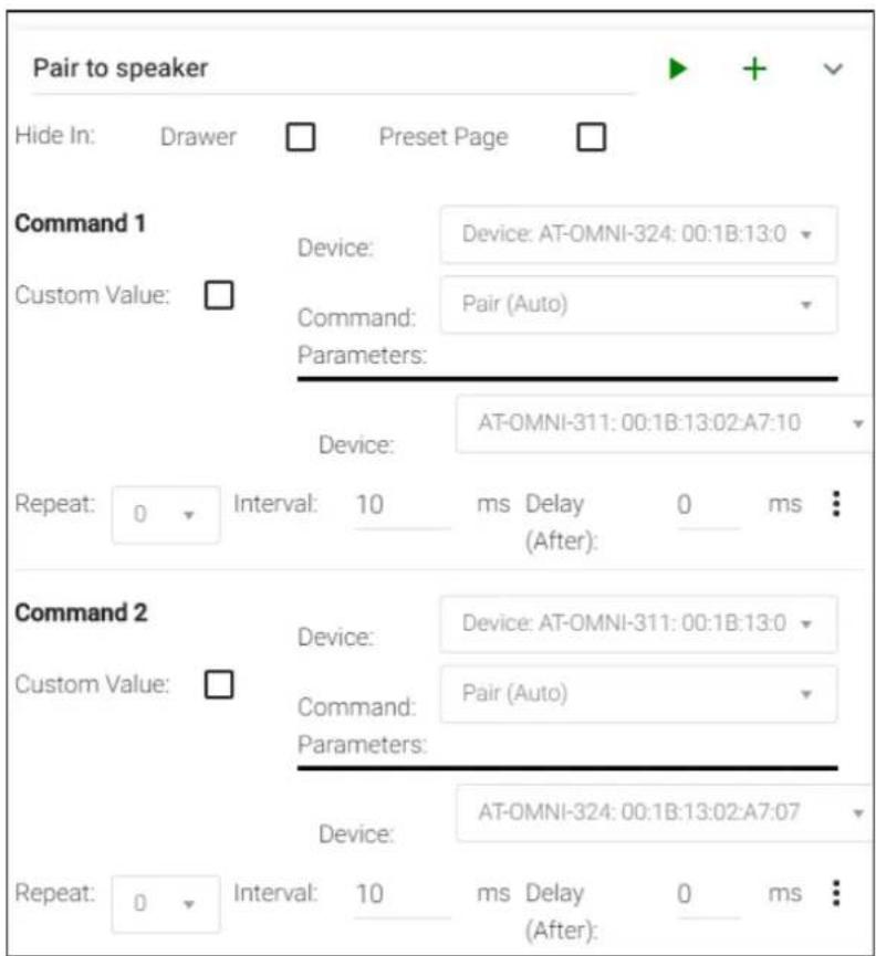
- Click the + icon, in the upper-right corner of the screen to create the final macro. This macro will be used to pair the computer with the speakerphone.
- Enter "Pair to speaker" in both the Name and Macro Commands text field.
- Click the + icon to display the macro configuration dialog.
- Click the Device drop-down list and select the AT-OMNI-324 that is connected to the speakerphone. The AT-OMNI-324 with the IP address of 192.168.11.123 will be selected
- Click the Command drop-down list and select Pair (Auto).
- Click the second Device drop-down list and select the AT-OMNI-311.
- Repeat steps 18 through 21: select the AT-OMNI-311 in the first Device drop-down list, and then the AT-OMNI-324 with the speakerphone, from the second Device drop-down list. The "Pair to speaker" macro should now appear as follows:
text_image
Pair to speaker Hide In: Drawer Preset Page Command 1 Device: Device: AT-OMNI-324: 00:1B:13:0 Custom Value: □ Command: Pair (Auto) Parameters: Device: AT-OMNI-311: 00:1B:13:02:A7:10 Repeat: 0 Interval: 10 ms Delay 0 ms (After): Command 2 Device: Device: AT-OMNI-311: 00:1B:13:0 Custom Value: □ Command: Pair (Auto) Parameters: Device: AT-OMNI-324: 00:1B:13:02:A7:07 Repeat: 0 Interval: 10 ms Delay 0 ms (After):- Click the Save icon in the top-right portion of the Room Macros bar.
DHCP Reset
Use the following instructions to reset the device to DHCP mode. Resetting to DHCP mode will not remove any pairings and if the device is already paired, it will remain paired.
-
Disconnect power from the unit.
-
Reconnect power to the unit, and within 5 seconds, press and hold the PAIRING button.

text_image
PAIRING button DC 24V UTILITY PAIRING LAN AT-OMNI-324-
Continue holding the PAIRING button for 15 seconds, then release.
-
Power-cycle the unit once again, by disconnecting and reconnecting the power. Let the unit boot up normally.
-
The unit is now in DHCP mode and will automatically be assigned an IP address by the DHCP server, if one is present on the network.
The AMS Interface
Device Info tab
The Device Info tab provides general information about the OmniStream 324. The OmniStream 311 has an identical interface.

text_image
DEVICE INFO NETWORK FINDING Device Info Name: AT OMNI 324 00.1b/13.02.92.a1 Model: AT OMNI 324 IP Address: 192.168.11.82 MAC Address: 00.1b/13.02.92.a1 SAVEAlias
Enter a name for the unit in this field. This is optional. By default, this field will be assigned the model number plus the MAC address of the unit.
Model
The model number of the unit.
IP Address
Displays the IP address of the unit.
MAC Address
Displays the MAC address of the unit.
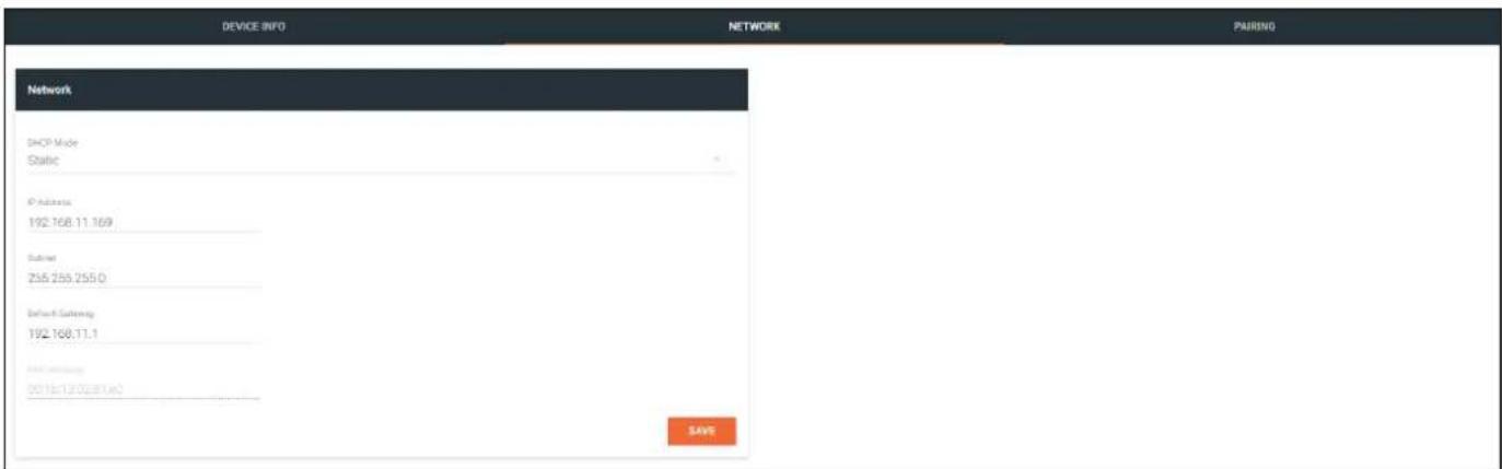
Network tab
The Network tab provides the ability to enable or disable DHCP mode. When DHCP mode is disabled, the IP address, subnet mask, and gateway must be provided.
text_image
DEVICE INFO NETWORK PAIRING Network DHCP Mode Static IP Address: 192.768.11.169 Subnet 258.258.255.0 Default Subneting: 192.168.11.1 Initial Subneting: 0013e13.00@1.m2 SAVEDHCP Mode
Click this drop-down list to select the desired network mode. Select DHCP to let the DHCP server (if present) assign the encoder the IP settings; Subnet and Gateway fields will automatically be populated. When Static mode is selected, the information for the IP Address, Subnet, and Gateway fields must be entered.
IP Address
Displays the IP address used by the channel. This field can only be changed if Static mode is selected.
Subnet
Displays the subnet mask for the channel. This field can only be changed if Static mode is selected.
Gateway
Displays the gateway (router) address for the channel. This field can only be changed if Static mode is selected.
MAC Address
The MAC address of the Ethernet channel.
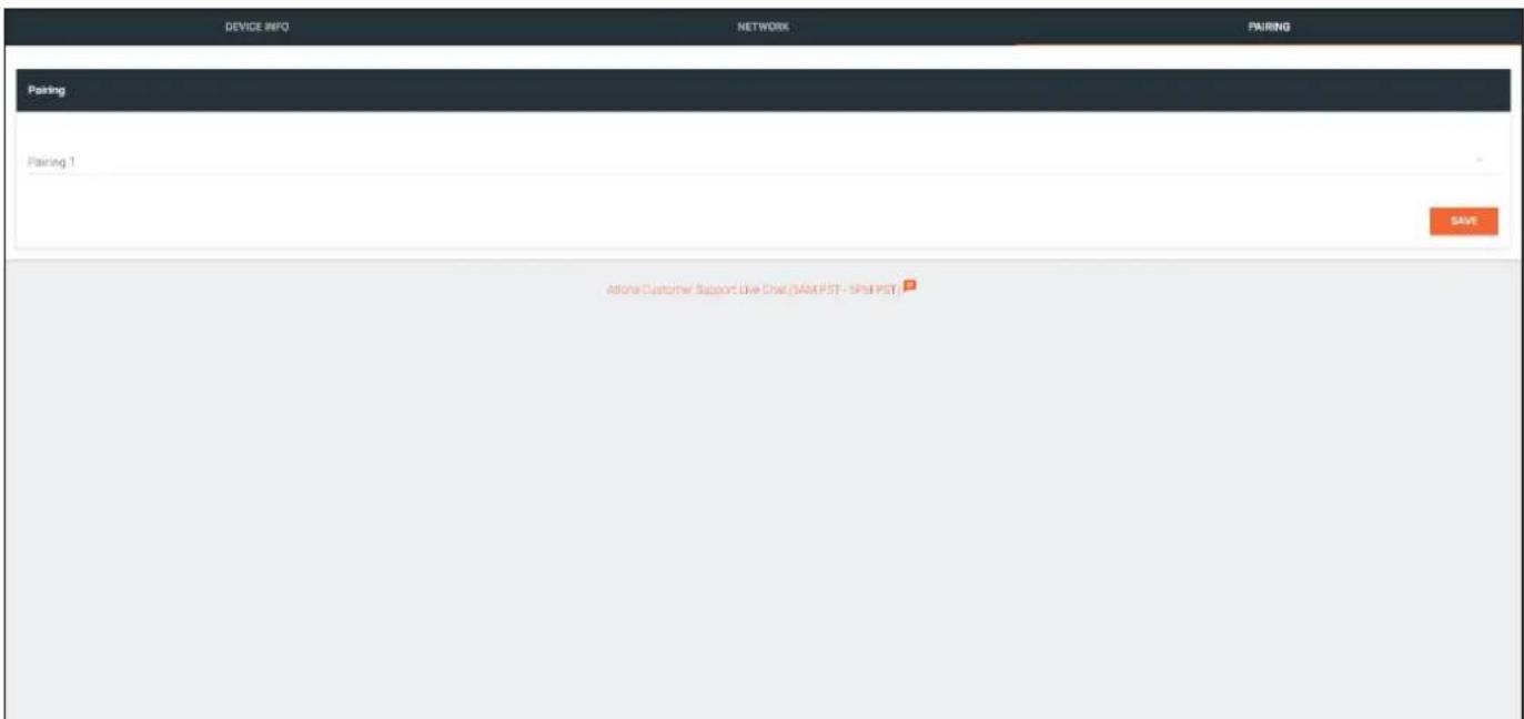
Pairing tab
The Pairing tab provides the ability to pair the OmniStream 324 with a OmniStream 311 device. Up to seven OmniStream 324 units can be paired to an OmniStream 311.
text_image
DEVICE INFO NETWORK PAIRING Pairing Pairing 1 SAVE Allone Customer Support Live Dist (SAM PST - SPSP PST)Pairing 1
Click this drop-down list to pair the OmniStream 324 with the desired OmniStream 311. To unpair an OmniStream 324 and an OmniStream 311, select the None option. Refer to Pairing (page 13) for more information.
Appendix
Mounting Instructions
The AT-OMNI-324 includes two mounting brackets, which can be used to attach the units to any flat surface.
- Remove the two enclosure screws, on both sides of the unit, using a small Phillips-head screwdriver.

natural_image
Black electronic device with ports and connectors, no visible text or symbols on body-
Position one of the mounting brackets, as shown below, aligning the holes on the side of the enclosure with one set of holes on the mounting bracket.
-
Attach the mounting brackets using the enclosure screws from Step 1.

natural_image
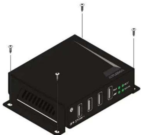
3D rendering of a black electronic device with ports and mounting brackets (no visible text or symbols)- Mount the unit using the oval-shaped holes, on each mounting bracket. If using a drywall surface, a #6 drywall screw is recommended.
natural_image
3D rendering of a black industrial electronic device with labeled ports and connectors (no readable text or symbols beyond labels)
NOTE: The unit can also be mounted under a table or other flat surface.
Appendix
Supported Cameras
The table below provides a list of webcams that have been tested and verified for use with the AT-OMNI-311 at USB 2.0 speeds.
| Manufacturer Model | |
| Atlona AT-HDVS-CAM | |
| Creative Live! Connect HD | Live! Cam inPerson HDLive! UltraLive! Cam Socialize |
| Logitech 9000 | 9000 ProC200C910C920Meetup*Orbit MPQuickCam Ultra Vision SEVision Pro |
| Microsoft 1080p HomeCinema | VX 500Lifecam Cinema 720pLifecam HD-5000Lifecam VX-2000 |
| Philips SPC900NC | |
*Although this is a USB 3.0 device, the test procedure was performed using a AT-OMNI-324 at USB 2.0 speeds.
Appendix
Specifications
| USB | |
| Signal 2.0 | |
| Maximum Data Rate 480 Mbps | |
| Distance Feet Meters | ||
| Per hop of Ethernet cable 330 100 | ||
| Connectors, Controls, and Indicators | |
| USB | 4 - Type A, 4-pin female |
| LAN | 1 - RJ45, shielded |
| UTILITY | 1 - 3.5 mm mini-stereo |
| PAIRING 1 - Push button, tact-type, recessed | |
| PWR indicator | 1 - LED, green |
| LINK indicator | 1 - LED, green |
| HOST indicator | 1 - LED, green |
| SIGNAL indicator | 1 - LED, green |
| Temperature | Fahrenheit | Celsius |
| Operating | 32 to 122 | 0 to 50 |
| Storage | -20 to 70 | -4 to 158 |
| Humidity | |
| Operating (RH) 20% to 80% (non-condensing) | |
| Storage (RH) 10% to 90% (non-condensing) |
| Dimensions Inches Millimeters | |
| H x W x D 1.04 x 3.92 x 3.01 26.40 x 99.50 x 76.45 | |
| Weight Pounds Kilograms | ||
| Device | 0.50 0.23 | |
| Certifications | |
| Device | CE, FCC, CB, RoHS |