
NETGEAR-GSM - Audio/video switch Atlona - Free user manual and instructions
Find the device manual for free NETGEAR-GSM Atlona in PDF.


| Product Type | Audio/Video Switch |
| Brand | Atlona |
| Model | NETGEAR-GSM |
| Dimensions (approx) | 20.0 x 15.0 x 4.5 cm |
| Weight (approx) | 0.8 kg |
| Power Supply | 12V DC, 1A external adapter |
| Input Ports | 4x HDMI |
| Output Ports | 1x HDMI |
| Supported Resolutions | Up to 4K@60Hz (3840x2160) |
| HDCP Support | HDCP 2.2 |
| Audio Formats | PCM, Dolby Digital, DTS |
| Remote Control | Infrared (included) |
| Operating Temperature | 0°C to 40°C |
| Housing Material | Metal |
| Mounting Options | Desktop or wall-mount (brackets included) |
| Warranty | 2 years |
| Maintenance | Clean with a soft, dry cloth. Do not use liquids. |
| Safety Warnings | Do not expose to moisture or extreme temperatures. |
| Spare Parts / Repairability | No user-serviceable parts. Contact support for repairs. |
| General Information | Designed for seamless switching between multiple HDMI sources. Supports CEC and ARC. |
Frequently Asked Questions - NETGEAR-GSM Atlona
User questions about NETGEAR-GSM Atlona
0 question about this device. Answer the ones you know or ask your own.
Ask a new question about this device
Download the instructions for your Audio/video switch in PDF format for free! Find your manual NETGEAR-GSM - Atlona and take your electronic device back in hand. On this page are published all the documents necessary for the use of your device. NETGEAR-GSM by Atlona.
USER MANUAL NETGEAR-GSM Atlona
AV Line of Fully Managed Switches M4250 Series
Firmware version 13.0.0 and later versions
NETGEAR, Inc.
350 E. Plumeria Drive November 2021
San Jose, CA 95134, USA202-12091-03
Support and Community
Visit netgear.com/support to get your questions answered and access the latest downloads.
You can also check out our NETGEAR Community for helpful advice at community.netgear.com.
Regulatory and Legal
(If this product is sold in Canada, you can access this document in Canadian French at https://www.netgear.com/support/download/.)
For regulatory compliance information including the EU Declaration of Conformity, visit https://www.netgear.com/about/regulatory/.
See the regulatory compliance document before connecting the power supply.
For NETGEAR's Privacy Policy, visit https://www.netgear.com/about/privacy-policy.
By using this device, you are agreeing to NETGEAR's Terms and Conditions at https://www.netgear.com/about/terms-and-conditions. If you do not agree, return the device to your place of purchase within your return period.
Do not use this device outdoors. The PoE source is intended for intra building connection only.
Applicable to 6 GHz devices only: Only use the device indoors. The operation of 6 GHz devices is prohibited on oil platforms, cars, trains, boats, and aircraft, except that operation of this device is permitted in large aircraft while ying above 10,000 feet. Operation of transmitters in the 5.925-7.125 GHz band is prohibited for control of or communications with unmanned aircraft systems.
Trademarks
© NETGEAR, Inc., NETGEAR, and the NETGEAR Logo are trademarks of NETGEAR, Inc. Any non-NETGEAR trademarks are used for reference purposes only.
Revision History
| Number | CommentsPublish DatePublication Part | |
| November 2021 | 2024 changed the following sections:Log in to the main UI with a web browser on page 26Log in to the main UI using the switch default IP address on page 26Congure the IPv4 service port on page 49Add an SNMPv3 user account on page 159Congure user password requirements on page 497Congure the HTTPS access settings on page 526Manage certificates for HTTPS access on page 528Generate an SSL certificate on page 529Delete an SSL certificate on page 531Transfer an existing HTTPS certificate from a server to the switch on page 531 | |
| We added the following sections:Display the status of the SSL certicates on page 528Activate a certificate on page 530 | ||
| We made other minor changes.We published the manual in a new format. | ||
| This second publication is a major revision.March 2021202-12091-02 | ||
| We added the following:Information about the 24-port PoE+ and PoE++ models and the 40-port PoE+ and PoE++ models (see Supported switches on page 23).Information about the Auto-Trunk feature (see Auto-Trunk overview on page 195 and Enable or disable Auto-Trunks on page 196).Information about the Auto-LAG feature (see Auto-LAG overview on page 302, Enable or disable Auto-LAGs on page 303, and Congure the hash mode for Auto-LAGs on page 304). | ||
| We revised a very large part of the manual and added multiple new sections to provide more complete and correct information. | ||
| We replaced the old appendix with defaults setting with a new one that also includes hardware specifications (see Software Default Settings and Hardware Specifications on page 784). | ||
| We made multiple corrections throughout the entire manual. | ||
| First publication.October 2020202-12091-01 |
Contents
Chapter 1 Get Started with the Main UI
Supported switches....23
Available publications and online help....24
Register your product....24
Main local browser UI overview....25
Log in to the main UI with a web browser....26
Log in to the main UI using the switch default IP address......26
Log in to the main UI with a known IP address......27
Main UI buttons and user-dened elds....28
Interface naming conventions....28
Save your settings to the running conguration....29
Main UI online help....29
Use the Device View in the Main UI....30
Set up SNMP access....32
Chapter 2 Congure Switch System Information
Switch system information....36
View and congure switch system information....36
View the fan status....39
View the temperature sensor information....40
View the device status and rmware version....41
View the system CPU status....42
Congure the CPU thresholds....43
View or clear switch statistics....44
View USB device information....46
Loopback interface....47
IPv4 management interfaces and VLANs....48
Congure the IPv4 service port....49
Congure an IPv4 management VLAN....50
Congure an IPv4 management interface....53
IPv6 management interfaces and VLANs....55
Congure an IPv6 service porttime....55
Manage IPv6 addresses for the IPv6 service port....57
Congure an IPv6 management VLAN....58
Manage IPv6 addresses for the IPv6 management VLAN......60
AV Line of Fully Managed Switches M4250 Series Main User Manual
Manage the IPv6 default route addresses for the IPv6 management VLAN....61
Congure an IPv6 management interface....62
Manage IPv6 addresses for the IPv6 management interface....64
Manage the IPv6 default route addresses for the IPv6 management interface....65
Time and SNTP settings....66
Congure the time setting manually....67
Congure the time settings with SNTP and congregate the global SNTP settings....67
View the SNTP global status....70
Congure SNTP servers....72
Add an SNTP server....73
Change the settings for an existing SNTP server....75
Remove an SNTP server....75
Congure daylight saving time settings....76
View the daylight saving time status....78
Precision Time Protocol....80
Manage the global PTP settings....80
Manage the PTP interface settings....81
Domain Name System....82
Congure the global DNS settings and add a DNS server.....82
Remove a DNS server....84
Congure and view host name-to-IP address information.....85
Add a static entry to the dynamic host mapping table......85
Remove an entry from the dynamic host mapping table.....86
Change the host name or IP address in an entry of the dynamic host mapping table, view all entries, or clear all entries.....86
Switch database management template....87
Green Ethernet settings....89
Congure the global green Ethernet settings....89
Congure green Ethernet interface settings....90
Congure and display detailed green Ethernet settings for an interface....91
Display green Ethernet information for the link partner of an interface....94
Display the green Ethernet statistics summary....95
Congure and display the green Ethernet EEE LPI history for an interface....97
Bonjour settings....98
Enable or disable Bonjour....99
Display Bonjour information....99
IPv4 DHCP server....100
Congure a DHCP server....100
Manage DHCP pools....102
AV Line of Fully Managed Switches M4250 Series Main User Manual
Create a DHCP pool....102
Change a DHCP pool....105
Remove a DHCP pool....106
Congure DHCP pool options....106
Display DHCP server statistics....107
Display the DHCP bindings....109
Delete one or all dynamic DHCP bindings......110
View bindings with DHCP conicts....110
Delete one or all DHCP bindings with conicts......112
DHCP relay and relay statistics....113
DHCP Layer 2 relay....114
Congure the global DHCP L2 relay settings....115
Congure a DHCP L2 relay interface....115
Display DHCP L2 relay interface statistics....117
UDP relay....118
Congure the global UDP relay settings and add a UDP switch configuration....118
Change a UDP switch conguration....120
Remove a UDP switch conguration....120
Add a UDP interface conguration....121
Change a UDP interface conguration....122
Remove a UDP switch conguration....123
DHCPv6 server....124
Enable the DHCPv6 server....124
Manage DHCPv6 pools....125
Create a DHCPv6 pool....125
Change a DHCPv6 pool....126
Delete a DHCPv6 pool....126
Manage DHCPv6 prex delegation for pools....127
Create a DHCPv6 prex delegation conguration for a pool....127
Change a DHCPv6 prex delegation conguration for a pool....128
Delete a DHCPv6 prex delegation conguration for a pool....129
Congure the DHCPv6 settings for an interface....130
Display the DHCPv6 bindings....131
Display DHCPv6 server statistics....132
Delete DHCPv6 statistics for one or all interfaces......135
DHCPv6 relay interface....136
Power over Ethernet....137
PoE concepts....137
Congure the global PoE settings....139
Congure the PoE ports settings....140
Power-cycle one or more PoE ports....144
AV Line of Fully Managed Switches M4250 Series Main User Manual
Timer schedules....145
Create a timer schedule....145
Specify the settings for an absolute timer schedule....146
Specify the settings for a recurring timer schedule....147
Change the settings for a recurring timer schedule entry.....149
Delete a timer schedule entry....150
Delete a timer schedule....151
Simple Network Management Protocol....152
Manage SNMPv1 and SNMPv2 communities....152
Add an SNMPv1 and SNMPv2 community....152
Change an existing SNMPv1 and SNMPv2 community.....153
Delete an SNMPv1 and SNMPv2 community....154
Manage the SNMPv1 and SNMPv2 trap settings.....154
Add an SNMPv1 or SNMPv2 trap conguration for a host.154
Change an SNMPv1 or SNMPv2 trap conguration for a host....156
Delete an SNMPv1 or SNMPv2 trap conguration for a host....156
Congure SNMPv1 and SNMPv2 trap ags....157
Display the supported MIBs....159
Manage SNMPv3 users....159
Add an SNMPv3 user account....159
Change an SNMPv3 user account....160
Delete an SNMPv3 user account....161
Link Layer Discovery Protocol....162
Congure the global LLDP settings....162
Congure LLDP interface settings....163
Display or clear LLDP statistics....164
Display LLDP local device information....166
Display LLDP remote device information....167
Display the LLDP remote device inventory....169
Link Layer Discovery Protocol for Media Endpoint Devices......170
Congure the global LLDP-MED settings....170
Congure LLDP-MED interface settings....171
Display LLDP-MED local device information....173
Display the LLDP-MED remote device information....175
Display the LLDP-MED remote device inventory......179
Link dependency....180
Congure a link dependency group....180
Congure or display upstream and downstream interfaces for a
link dependency group....181
Clear all interfaces in a link dependency group....183
Industry Standard Discovery Protocol....184
Congure the global ISDP settings....184
Congure ISDP settings for an interface....186
AV Line of Fully Managed Switches M4250 Series Main User Manual
Display or clear ISDP neighbor information....187
Display or clear ISDP statistics....188
Chapter 3 Congure Switching Information
VLANs....191
Manage the VLAN congruration on the switch....191
Add a VLAN....191
Change a VLAN....192
Delete one or more VLANs....193
Reset the entire VLAN congruration to default setting.....194
Change the internal VLAN allocation settings....194
Auto-Trunk overview....195
Enable or disable Auto-Trunks....196
Congure the switch port mode settings for interfaces......197
Congure membership interfaces for a VLAN....199
View the VLAN status on the switch....201
Change the port VLAN ID settings....202
Congure a MAC-based VLAN....205
Add a MAC-based VLAN conguration....205
Delete a MAC-based VLAN conguration....206
Congure a protocol-based VLAN group....206
Add a protocol-based VLAN group....207
Change a protocol-based VLAN group....208
Delete a protocol-based VLAN group....209
Congure membership interfaces for a protocol-based VLAN group....209
Congure an IP subnet-based VLAN....211
Add an IP subnet-based VLAN....211
Delete an IP subnet-based VLAN....212
Congure a double VLAN....212
Congure a voice VLAN....214
Congure Generic Attribute Registration Protocol......216
Congure GARP switch settings....216
Congure GARP settings for one or more interfaces......217
Auto-VoIP....219
Congure Auto-VoIP protocol-based settings....219
Congure the Auto-VoIP OUI-based properties......220
Congure the OUI-based interface settings....221
Manage the OUI table....222
Add an OUI prex....223
Delete one or more OUI prexes....224
Display the Auto-VoIP status....224
Spanning Tree Protocol....225
Congure the STP settings and display the STP status.....226
AV Line of Fully Managed Switches M4250 Series Main User Manual
Congure the CST settings and display the CST status.....229
Congure the CST interface settings....231
Display the CST interface Status....234
Manage MST instances....236
Add an MST instance and display the MST status......236
Change an MST instance....238
Delete an MST instance....238
Congure and display the interface settings for an MST instance....239
Display the STP interface statistics....242
Congure the PVST/RPVST VLAN settings....243
Change a PVST/RPVST VLAN conguration....245
Remove a PVST/RPVST VLAN conguration....246
Congure the PVST and RPVST interface settings.....246
Display the PVST and RPVST statistics....248
Multicast forwarding database....249
Display the entries in the multicast forwarding database.....249
Remove the IGMP snooping entries from the multicast forwarding database....250
Remove all known multicast MAC entries from the multicast forwarding database....251
Display the multicast forwarding database statistics......252
Internet Group Management Protocol snooping......253
Congure IGMP snooping automatically with IGMP Plus mode....254
Congure IGMP snooping manually....255
Congure the IGMP snooping settings for interfaces......257
Congure IGMP snooping for VLANs automatically with IGMP Plus mode....259
Congure IGMP snooping for VLANs manually....260
Congure an IGMP multicast router interface....262
Congure an IGMP multicast router VLAN....263
IGMP snooping querier overview....264
Congure the IGMP snooping querier global settings......264
Congure an IGMP snooping querier for a VLAN....265
Remove the IGMP snooping querier settings for a VLAN.....267
Display the status of the IGMP snooping querier......268
Multicast Listener Discovery snooping......269
Configure MLD snooping automatically with MLD Plus mode.269
Congure MLD snooping manually....271
Congure the MLD snooping settings for interfaces......272
Congure MLD snooping for VLANs automatically with MLD Plus mode....274
Congure MLD snooping for VLANs manually....275
Remove the MLD snooping querier settings for a VLAN.....277
AV Line of Fully Managed Switches M4250 Series Main User Manual
Congure an MLD multicast router interface....278
Congure an MLD multicast router VLAN....279
Congure the MLD snooping querier global settings.....280
Congure an MLD snooping querier for a VLAN....281
Remove the MLD snooping querier settings for a VLAN.....283
Multicast VLAN registration....283
Congure the global MVR settings....284
Congure an MVR group....285
Remove an MVR group....286
Congure an MVR interface....287
Congure the interface members of an MVR group......288
Display the MVR statistics....289
MAC address table....290
View, search, or clear the MAC address table....290
Set the dynamic address aging interval....292
Add a static MAC address to the MAC address table.....293
Remove a static MAC address from the MAC address table..293
Port settings....294
Congure and display the port settings....294
Add port, LAG, and VLAN descriptions....297
Display transceiver module information....299
Congure the port link ap settings....300
Link aggregation groups....301
Auto-LAG overview....302
Enable or disable Auto-LAGs....303
Congure the hash mode for Auto-LAGs....304
Congure the LAG settings....305
Congure a single LAG and its membership....307
802.1AS timing and synchronization....309
Congure and view the global 802.1AS settings....309
Congure the 802.1AS interface settings....310
View the 802.1AS statistics....313
Multiple Registration Protocol settings....315
Congure the global MRP settings....316
Congure 802.1Qav mapping....318
Congure the MRP interface settings....318
View or clear MMRP statistics....321
View or clear MVRP statistics....322
View or clear MSRP statistics....324
View the MSRP reservation settings....326
Congure and view the Qav settings for interfaces......328
View MSRP streams information....330
Loop protection....332
About loop protection....332
Congure the global loop protection settings....334
AV Line of Fully Managed Switches M4250 Series Main User Manual
Congure the loop protection settings for interfaces and display the loop protection state....335
Chapter 4 Manage Routing
Routing concepts....338
Routing table, routes and route preferences....338
Congure a route and display learned routes....338
Delete a route....340
Specify route preferences....341
IPv4 routing....342
Manage the global IPv4 routing settings....342
Display the IPv4 statistics....344
Congure IPv4 routing interfaces....347
Delete the routing IP address from an IPv4 routing interface.350
Congure a secondary IP address for an IPv4 routing interface....351
Delete the secondary IP address from an IPv4 routing interface....352
IPv6 routing....353
Manage the global IPv6 routing settings....353
Display the IPv6 route table....354
Congure IPv6 routing interfaces....355
Congure prex settings for an IPv6 routing interface......358
Delete a prex setting from an IPv6 routing interface......360
Display the IPv6 and ICMPv6 statistics for an IPv6 routing interface....361
Display the IPv6 neighbor table or clear IPv6 neighbor entries.366
Congure IPv6 static routes....368
Delete an IPv6 static route....370
Congure the IPv6 route preference for the switch....370
Congure IPv6 tunnels....371
Delete an IPv6 tunnel....373
Routing VLANs....373
Create a routing VLAN with the VLAN static routing wizard...374
Congure routing for an existing VLAN....375
Remove the routing function from a VLAN....376
Address Resolution Protocol....377
Display the ARP entries in the ARP cache....378
Add or change a static entry in the ARP table....379
Delete a static ARP entry....380
Congure the ARP table settings or remove entries from the table....381
Routing Information Protocol....383
Enable or disable RIP on the switch....384
AV Line of Fully Managed Switches M4250 Series Main User Manual
Congure the global RIP settings for the switch....384
Congure RIP interface settings....386
Congure the RIP route redistribution settings and display the route redistribution summary....388
Router discovery and router advertisements....390
Chapter 5 Congure Multicast Routing
IPv4 multicast routing and the IPv4 multicast route table......394
Display the IPv4 multicast route table....394
Add static multicast entries to the IPv4 Mroute table......395
Delete a static multicast entry from the IPv4 Mroute table.....396
Congure global multicast settings for the switch....397
Congure a multicast interface....398
IGMP for IPv4 multicast routing....399
Congure the global IGMP settings for the switch....399
Congure an IGMP routing interface....400
Display the statistics for the IGMP routing interfaces......402
Display the IGMP groups and search the IGMP group database....403
Display the IGMP membership information and search the IGMP membership database....405
Congure an IGMP proxy interface....407
Display the statistics for the IGMP proxy interface......408
Display the IGMP proxy membership and search the IGMP proxy membership database....410
PIM for IPv4 multicast routing....411
Congure the global PIM IPv4 settings on the switch.....412
Add IPv4 PIM-SSM groups....412
Delete an IPv4 PIM-SSM group....413
Congure an IPv4 PIM interface....414
Display IPv4 PIM neighbors and search the PIM neighbor database....416
Add an IPv4 PIM candidate rendezvous point conguration.417
Delete an IPv4 PIM candidate rendezvous point configuration.418
Congure an interface as an IPv4 PIM bootstrap router candidate....419
Delete an IPv4 PIM bootstrap router candidate configuration.420
Congure a static IPv4 PIM rendezvous point for a group.....421
Delete a static IPv4 PIM rendezvous point conguration.....422
Static multicast routes for IPv4 addresses....422
Congure static multicast routes for IPv4 addresses.....422
Delete a static multicast route for an IPv4 address......423
Multicast admin boundaries for IPv4 addresses....424
Congure an interface as a multicast admin boundary......424
AV Line of Fully Managed Switches M4250 Series Main User Manual
Delete a multicast admin boundary conguration for an interface....425
IPv6 multicast routing and the IPv6 multicast route table......426
Display the IPv6 multicast route table....426
PIM for IPv6 multicast routing....428
Congure the global PIM IPv6 settings on the switch.....428
Add IPv6 PIM-SSM groups....429
Delete an IPv6 PIM-SSM group....430
Congure an IPv6 PIM interface....430
Display IPv6 PIM neighbors and search the PIM neighbor database....432
Add an IPv6 PIM candidate rendezvous point conguration.433
Delete an IPv6 PIM candidate rendezvous point configuration.434
Congure an interface as an IPv6 PIM bootstrap router candidate....435
Delete an IPv6 PIM bootstrap router candidate configuration.436
Congure a static IPv6 PIM rendezvous point for a group.....437
Delete a static IPv6 PIM rendezvous point conguration.....438
MLD for IPv6 multicast routing......439
Congure the global MLP settings for the switch......439
Congure an MLD routing interface....440
Display the statistics for the MLD routing interfaces......442
Display the MLD groups and search the MLD group database.443
Display or clear MLD trafc statistics....445
Congure an MLD proxy interface....446
Display the statistics for the MLD proxy interface......447
Display the MLD proxy membership and search the MLD proxy membership database....449
Static multicast routes for IPv6 addresses....450
Congure static multicast routes for IPv6 addresses......451
Delete a static multicast route for an IPv6 address......452
Chapter 6 Congure Quality of Service
Quality of Service concepts....454
Class of Service....454
CoS conguration concepts....454
Congure the CoS trust mode settings globally or for a specific interface....455
Map 802.1p priorities to queues....456
Map DSCP values to queues....458
Congure the CoS interface settings for an interface......458
Congure CoS queue settings for an interface......460
Congure the CoS WRED precedence settings for dropping packets....462
AV Line of Fully Managed Switches M4250 Series Main User Manual
Differentiated Services....464
Dening DiffServ....464
DiffServ wizard overview....465
Use the DiffServ wizard to create a traffic class and policy for one or more interfaces....466
Congure the DiffServ mode and display the entries in the DiffServ private MIB tables....467
Congure a DiffServ class....468
Add and congure a DiffServ class....469
Rename an existing DiffServ class....473
Change the criteria for an existing DiffServ class......473
Delete a DiffServ class....474
Congure an IPv6 DiffServ class....475
Add and congrure an IPv6 DiffServ class....475
Rename an existing IPv6 DiffServ class....478
Change the criteria for an existing IPv6 DiffServ class.....478
Delete an IPv6 DiffServ class....479
Congure a DiffServ policy....480
Create and congregate a DiffServ policy......480
Rename an existing DiffServ policy....486
Change the policy attributes for an existing DiffServ policy.486
Change or remove a class from an existing DiffServ policy.487
Delete a DiffServ policy....488
Congure the DiffServ service interface....488
Attach DiffServ policies to an interface....488
Change one or both DiffServ policies for an interface.....490
Remove one or both DiffServ policies from an interface....491
Display DiffServ service statistics....492
Chapter 7 Manage Switch Security
User accounts and passwords....495
Add or change a user account....495
Delete a user account....496
Congure user password requirements....497
Change the privileged EXEC CLI password....498
Change the console, Telnet, or SSH password....499
RADIUS servers....500
Congure the global RADIUS server settings....500
Congure a RADIUS authentication server on the switch.....503
Add a RADIUS authentication server to the switch......503
Modify the settings for a RADIUS authentication server on the switch....505
Remove a RADIUS authentication server from the switch..506
Congure a RADIUS accounting server....507
AV Line of Fully Managed Switches M4250 Series Main User Manual
Add a RADIUS accounting server to the switch....507
Modify the settings for a RADIUS accounting server on the switch....509
Remove a RADIUS accounting server from the switch.....510
TACACS+ serversConguration TACACS....510
Congure the global TACACS+ settings....511
Add a TACACS+ server to the switch....512
Modify the settings for a TACACS+ server on the switch.....513
Remove a TACACS+ server from the switch....514
Authentication lists....514
Congure a login authentication list....514
Delete a login authentication list....516
Congure an enable authentication list....517
Delete an enable authentication list....519
Congure the Dot1x authentication list....520
Congure the HTTP authentication list....521
Congure the HTTPS authentication List....522
Current login sessions....523
HHTP and HTTPS management access....524
Congure HTTP access settings....524
Congure the HTTPS access settings....526
Browser security message with HTTPS access....527
Manage certificates for HTTPS access....528
Display the status of the SSL certificates....528
Generate an SSL certificate....529
Activate a certificate....530
Delete an SSL certificate....531
Transfer an existing HTTPS certificate from a server to the switch....531
SSH management access....533
Congure the global SSH access settings....534
Manage RSA and DSA keys for SSH access....535
Generate an RSA or DSA key....535
Delete an RSA or DSA key....536
Transfer existing SSH keys from a TFTP server to the switch.537
Telnet management access....539
Select Telnet authentication lists....539
Congure Inbound Telnet settings....540
Congure outbound Telnet settings....541
Console port management access....542
Denial of service....544
Management access proles and rules....546
Add an access prole....546
Add a rule to the access prole....547
Activate the access prole....548
AV Line of Fully Managed Switches M4250 Series Main User Manual
Display the access prole summary and the number of itered packets....549
Deactivate an access prole....550
Remove an access prole....551
Port authenticationport authentication....551
Congure the global 802.1X settings....552
Manage port authentication on individual ports......554
Congure 802.1X settings for a port....554
Initialize 802.1X on a port....558
Display the port summary....559
Display the client summary....561
MAC Iters for trafc control....563
Create a MAC Iter....563
Delete a MAC Iter....565
Display the MAC Iter summary....566
Port security....567
Congure the global port security mode....567
Congure a port security interface....568
Display learned MAC addresses and convert them to static addresses....569
Add a static MAC address to the MAC address table for port security....571
Remove a static MAC address from the MAC address table for port security....571
Private port groups....572
Add a private port group....572
Remove a private port group....573
Congure the membership of a private port group....574
Protect ports....575
Private VLANs....576
Overview of the tasks for private VLAN congruration......577
Assign a private VLAN type to a VLAN....578
Congure a private VLAN association with a primary and secondary VLAN....579
Remove an existing private VLAN association....581
Congure the private VLAN port mode....581
Private VLAN host interface: Assign the interface to primary and secondary VLANs....583
Private VLAN host interface: Remove the interface from primary and secondary VLANs....585
Private VLAN promiscuous interface: Assign the interface to primary and secondary VLANs....586
Private VLAN promiscuous interface: Remove the interface from primary and secondary VLANs....587
Private VLAN promiscuous trunk interface: Add primary and secondary VLANs to the trunk....589
Private VLAN promiscuous trunk interface: Remove primary and secondary VLANs from the trunk....590
Private VLAN isolated trunk interface: Add primary and secondary VLANs to the trunk....591
Private VLAN isolated trunk interface: Remove primary and secondary VLANs from the trunk....592
Congure native and allowed VLANs on a private VLAN trunk interface....593
Storm control....595
Congure global storm control settings....595
Congure storm control settings for one or more ports.....597
DHCP snooping....599
Enable DHCP snooping for the switch....600
Enable DHCP snooping for a VLAN....600
Congure DHCP snooping interface settings....601
Add a static DHCP binding and display dynamic DHCP bindings....60
Remove a static DHCP binding....604
Congure DHCP snooping persistent settings....605
Display or clear DHCP snooping statistics....606
DHCPv6 snooping....607
Enable DHCPv6 snooping for the switch....607
Enable DHCPv6 snooping for a VLAN....608
Congure DHCPv6 snooping interface settings....609
Add a static DHCPv6 binding and display dynamic DHCPv6 bindings....611
Remove a static DHCPv6 binding....612
Congure DHCPv6 snooping persistent settings......613
Display or clear DHCPv6 snooping statistics....614
IP source guard interfaces....615
Congure IP source guard on an interface....615
Add a static IP source guard binding and display dynamic IP source guard bindings....617
Remove a static IP source guard binding....618
IPv6 source guard interfaces....619
Congure IPv6 source guard on an interface....619
Add a static IPv6 source guard binding and display dynamic IPv6 source guard bindings....621
Remove a static IPv6 source guard binding....622
Dynamic ARP inspection....623
Congure the global DAI settings....623
Congure DAI VLANs....624
Congure DAI interfaces....625
AV Line of Fully Managed Switches M4250 Series Main User Manual
Create a DAI access control list....627
Congure a rule for an existing DAI ACL....627
Delete a rule from an existing DAI ACL....628
Delete a DAI access control list....629
Display the DAI statistics....630
Captive portals....631
Congure the global captive portal settings....632
Congure a captive portal....634
Delete a captive portal....637
Congure a captive portal binding....638
Display or delete captive portal bindings in the captive portal
binding table....638
Congure captive portal groups....640
Add a captive portal group....640
Remove a captive portal group....641
Congure captive portal users....641
Add or modify a captive portal user account......642
Delete a captive portal user account....644
Congure the captive portal trap ag settings....644
Display or clear captive portal client statistics....645
Access control lists....647
Use the ACL Wizard to create a simple ACL....647
Use the ACL Wizard to create an ACL....647
Modify an ACL rule that you created with the ACL Wizard.652
Delete an ACL rule that you created with the ACL Wizard.652
ACL Wizard example....653
Congure a MAC ACL....653
Add a MAC ACL....654
Change the name of a MAC ACL....655
Delete a MAC ACL....655
Congure MAC ACL rules....656
Add a rule to a MAC ACL....656
Change the match criteria for a MAC rule....659
Delete a rule for a MAC ACL....659
Congure MAC bindings....660
Display or delete MAC ACL bindings in the MAC binding
table....662
Congure a basic or extended IPv4 ACL....663
Add an IPv4 ACL....664
Change the number or name of an IPv4 ACL....665
Delete an IPv4 ACL....666
Congure rules for a basic IP ACL....666
Add a rule for a basic IPv4 ACL....667
Modify the match criteria for a basic IPv4 ACL rule......669
Delete a basic IPv4 ACL rule....670
AV Line of Fully Managed Switches M4250 Series Main User Manual
Congure rules for an extended IPv4 ACL....671
Add a rule for an extended IPv4 ACL....671
Modify the match criteria for an extended IPv4 ACL rule...678
Delete an extended IPv4 ACL rule....679
Congure an IPv6 ACL....679
Add an IPv6 ACL....680
Change the name of an IPv6 ACL....681
Delete an IPv6 ACL....681
Congure rules for an IPv6 ACL....682
Add a rule for an IPv6 ACL....682
Modify the match criteria for an IPv6 ACL rule....687
Delete an IPv6 ACL rule....688
Congure IP ACL interface bindings....688
Display or delete IP ACL bindings in the IP ACL binding table.690
Congure VLAN ACL bindings....692
Add a VLAN ACL binding....692
Remove a VLAN ACL binding....693
Chapter 8 Monitor the Switch and Network
Port and EAP packet statistics....695
Display or clear port statistics....695
Display or clear detailed statistics for a port......696
Display or clear EAP and EAPoL statistics....703
Perform a cable test....705
Logs....706
Manage and display the memory log....706
Message log format....709
Enable or disable the command conguration log....709
Enable or disable console logging....710
Syslog and log server host settings....711
Congure the syslog settings....712
Add a syslog server....713
Modify the settings for a syslog server....714
Delete the settings for a syslog server....715
Trap log....716
Event log....717
Port mirroring....718
RSPAN VLANs and source and destination switches....721
Congure an existing VLAN as an RSPAN VLAN....721
Congure the switch as an RSPAN source switch....722
Congure the switch as an RSPAN destination switch......724
sFlow monitoring....725
sFlow agent overview....726
Congure the source interface for the sFlow agent....726
AV Line of Fully Managed Switches M4250 Series Main User Manual
Congure an sFlow receiver....727
Congure sFlow polling and sampling on an interface......729
Display license information....730
Display license key information....730
Display features to which the license applies....731
Chapter 9 Maintenance and Troubleshooting
Save the conguration....734
Automatic installation of the conguration le....734
Congure the auto install process....734
Option 125 DHCP server requirements for obtaining an conguration le through auto install....736
Reboot the switch from the main local browser UI....737
Reset the switch to the factory default settings....738
Export a le from the switch....739
Export a le from the switch to a server....739
Use HTTP to export a le from the switch to a computer.....741
Export a le from the switch to a USB storage device....742
Upgrade software or download a le....743
Upgrade the software image or download a le from a server to the switch....744
Use HTTP to download a le to the switch or update the software image....747
Download a le from a USB storage device to the switch.....749
Use an HTTP session to download and install an SSL security certificate le on the switch....750
Manage software images le management....752
Copy an software image....752
Congure dual image settings....752
Change the software image that loads when the switch starts or reboots....753
Delete a software image....754
Diagnostics and troubleshooting....754
Ping an IPv4 address....755
Ping an IPv6 address....756
Send an IPv4 traceroute....758
Send an IPv6 traceroute....760
Capture Packets....761
Perform a full memory dump....762
Appendix A Conguration Examples
Virtual Local Area Networks (VLANs)....766
VLAN conguration examples....767
Access control lists (ACLs)....768
AV Line of Fully Managed Switches M4250 Series Main User Manual
MAC ACL sample conguration....769
Basic IP ACL sample conguration....770
Differentiated Services (DiffServ)....771
Class....772
DiffServ trafc classes....772
Create policies....773
Trafc conditioning policy....773
DiffServ example conguration....774
802.1X access control....775
802.1X example conguration....777
Multiple Spanning Tree Protocol....779
MSTP example conguration....780
VLAN routing interfaces....782
Appendix B Software Default Settings and Hardware Specifications
Access default settings for the switch device UI....785
System features default settings....785
Switching features default settings....790
Routing and multicast features default settings....800
QoS features default settings....805
Security features default settings....807
Monitoring features default settings....816
Model-specific hardware technical specifications....818
Model M4250-10G2F-PoE+ (SKU GSM4212P)......818
Model M4250-10G2XF-PoE+ (SKU GSM4212PX)......819
M4250-10G2XF-PoE++ (SKU GSM4212UX)......819
M4250-26G4F-PoE+ (SKU GSM4230P)......820
M4250-26G4XF-PoE+ (SKU GSM4230PX)....821
M4250-26G4F-PoE++ (SKU GSM4230UP)....821
M4250-40G8F-PoE+ (SKU GSM4248P)....822
M4250-40G8XF-PoE+ (SKU GSM4248PX)....823
M4250-40G8XF-PoE++ (SKU GSM4248UX)....823
M4250-12M2XF (SKU MSM4214X)....824
M4250-16XF (SKU XSM4216F)......824
General hardware technical specifications....825
1
Get Started with the Main UI
This user manual is for the AV Line of Fully Managed Switches M4250 Series and cover all M4250 switch models.
This chapter provides an overview of how you can using your switch and access the main local browser user interface (UI).
The chapter contains the following sections:
• Supported switches
• Available publications and online help
- Register your product
- Main local browser UI overview
- Log in to the main UI with a web browser
- Use the Device View in the Main UI
- Set up SNMP access
Note: For more information about the topics covered in this manual, visit the support website at_netgear.com/support.
Note: Firmware updates with new features and bug xes are made available from time to time at netgear.com/support/download/. Some products can regularly check the site and download new firmware, or you can check for and download new firmware manually. If the features or behavior of your product does not match what is described in this guide, you might need to update your rmware.
Supported switches
This release and this main user manual are for the following M4250 switch models:
• 8-port PoE+ and PoE++ models:
- M4250-10G2F-PoE+ (SKU GSM4212P): Eight PoE+ (802.3at) 1GBASE-T RJ-45 ports, two 1GBASE-T RJ-45 ports, and two 1G SFP ber uplink ports. The total PoE budget for the switch is 125W.
- M4250-10G2XF-PoE+ (SKU GSM4212PX): Eight PoE+ (802.3at) 1GBASE-T RJ-45 ports, two 1GBASE-T RJ-45 ports, and two 10G SFP+ ber uplink ports. The total PoE budget for the switch is 240W.
- M4250-10G2XF-PoE++ (SKU GSM4212UX): Eight PoE++ (802.3bt) 1GBASE-T RJ-45 ports, two 1GBASE-T RJ-45 ports, and two 10G SFP+ ber uplink ports. The total PoE budget for the switch is 720W.
• 24-port PoE+ and PoE++ models:
- M4250-26G4F-PoE+ (SKU GSM4230P): 24 PoE+ (802.3at) 1GBASE-T RJ-45 ports, two 1GBASE-T RJ-45 ports, and four 1G SFP ber uplink ports. The total PoE budget for the switch is 300W.
- M4250-26G4XF-PoE+ (SKU GSM4230PX): 24 PoE+ (802.3at) 1GBASE-T RJ-45 ports, two 1GBASE-T RJ-45 ports, and four 10G SFP+ ber uplink ports. The total PoE budget for the switch is 480W.
- M4250-26G4F-PoE++ (SKU GSM4230UP): 24 PoE++ (802.3bt) 1GBASE-T RJ-45 ports, two 1GBASE-T RJ-45 ports, and four 10G SFP+ ber uplink ports. The total PoE budget for the switch is 1440W with both internal power supply units connected
• 40-port PoE+ and PoE++ models:
- M4250-40G8F-PoE+ (SKU GSM4248P): 40 PoE+ (802.3at) 1GBASE-T RJ-45 ports and eight 1G SFP ber uplink ports. The total PoE budget for the switch is 480W.
- M4250-40G8XF-PoE+ (SKU GSM4248PX): 40 PoE+ (802.3at) 1GBASE-T RJ-45 ports and eight 10G SFP+ ber uplink ports. The total PoE budget for the switch is 960W.
- M4250-40G8XF-PoE++ (SKU GSM4248UX): 40 PoE++ (802.3bt) 1GBASE-T RJ-45 ports and eight 10G SFP+ ber uplink ports. The total PoE budget for the switch is 2880W with all three internal power supply units connected.
- Special models:
- M4250-12M2XF (SKU MSM4214X): LED tiles model with 2.5 Gbps ports. Twelve 2.5GBASE-T RJ-45 ports and two 10G SFP+ ber uplink ports.
- M4250-16XF (SKU XSM4216F): Aggregation model with sixteen 10G SFP+ ber ports. Twelve ports also support 1G speed with autonegotiation. Four ports can be manually set to 1G speed.
Available publications and online help
You can download the following publications for the AV Line of Fully Managed Switches: M4250 Series by visiting_netgear.com/support/download/.
- Installation Guide
• Hardware Installation Guide
• Main User Manual (this manual)
• Audio Video User Manual - Software Administration Manual
• CLI Command Reference Manual
You can also access this document online when you are logged in to the switch by selecting Help > Online Help > User Guide.
When you log into the main local browser UI, online help is available. See Main UI or help on page 29.
Register your product
To qualify for product updates and product warranty, we encourage you to register your product. The rst time that you log in to the switch, you can register with NETGEA by clicking the Register now button.
Registration conrms that your email alerts work, lowers technical support resolution time, and ensures that your shipping address accuracy. We would also like to incorporate your feedback into future product development. We never sell or rent your email address and you can opt out of communications.
To register your switch with NETGEAR:
-
Visit the NETGEAR website for registration at https://my.netgear.com/registration/login.aspx.
-
Click the Login button, and follow the directions onscreen to register the switch with your NETGEAR email address and password.
If you did not yet create a NETGEAR account, click the Create account link, follow the directions onscreen to create an account, and then register the switch with your NETGEAR email address and password.
Main local browser UI overview
Your switch contains an embedded web server and management software for managing and monitoring switch functions. The switch functions as a simple switch without the management software. However, you can use the management software to congregate more advanced features that can improve switch efficiency and overall network performance.
The switch software includes a set of comprehensive management functions for conguring and monitoring the system by using one of the following methods:
- Main local browser user interface (main UI), either over an Ethernet network port or over the out-of-band (OOB) port (also referred to as the service port)
- Audio-video local browser user interface (AV UI), either over an Ethernet network port or over the OOB port
- Simple Network Management Protocol (SNMP)
• Command-line interface (CLI)
Each of the standards-based management methods allows you to configure and monitor the components of the switch. The method you use to manage the system depends on your network size and requirements, and on your preference.
This manual describes how to use the main local browser user interface (UI) to manage and monitor the switch. We abbreviate the main local browser UI as the main UI.
The main UI is a web-based management tool that lets you monitor, congregate, and control your switch remotely using a standard web browser. From your web browser, you can monitor the performance of your switch and optimize its congruration for your network. You can congregate all available switch features, such as VLANs, QoS, and ACLs, by using the main UI.
Log in to the main UI with a web br
If this is the rst time that you log in to the switch and you must use the default IP a of the switch, see the information in the installation guide.
You can use a web browser to access the switch and log in. You must be able to pin the IP address of the management interface or out-of-band (OOB) port from your computer for web access to be available.
By default, no IP address is set for the OOB port, but its DHCP client is enabled so that the port can receive an IP address from a DHCP server in your network. If the OOB port does not receive an IP address from a DHCP server in your network, the IP address for the port is set to 192.168.0.239 with 255.255.255.0 as the subnet mask. The same occurs if you connect the OOB port directly to a computer and reboot the switch.
Note: The rst time that you log in as an admin user to the main UI, no password is required (that is, the password is blank). After you log in for the first time, you are required to specify a local device password that you must use each subsequent time that you log in. (You can change the password again.)
Log in to the main UI using the switch default IP:
To use the switch default IP address to access the switch over the main UI:
- Prepare your computer with a static IP address:
- For access over an Ethernet network port, use a static IP address in the 169.254.0.0 subnet with subnet mask 255.255.0.0.
For example, use 169.254.100.201 for your computer.
- For access over the OOB port, use a static IP address in the 192.168.0.0 subnet with subnet mask 255.255.0.0.
For example, use 192.168.0.201 for your computer.
-
Connect an Ethernet cable from an Ethernet port on your computer to either an Ethernet network port on the switch or to the OOB port on the switch.
-
If you are using the OOB port, reboot the switch so that the IP address for the OOB port is set to 192.168.0.239 with 255.255.255.0 as the subnet mask.
-
Launch a web browser such as Google Chrome, Mozilla Firefox, or Microsoft Edge.
-
Enter the default IP address of the switch in the web browser address eld:
- For access over an Ethernet network port, enter 169.254.100.100.
- For access over the OOB port, enter 192.168.0.239.
The login page displays.
- Click the Main UI Login button.
The main UI login page displays in a new tab.
- Enter admin as the user name, enter your local device password, and click the Login button.
The rst time that you log in, no password is required. However, you then must specify a local device password to use each subsequent time that you log in.
The System Information page displays.
Log in to the main UI with a known IP address
If you did not assign a static IP address to the switch but let a DHCP server in your network assign an IP address to switch, determine the IP address by accessing the DHCP server or by using an IP scanner utility.
The procedures in this manual assume that you know the IP address of your switch.
To use a known IP address to access the switch over the main UI:
-
Launch a web browser.
-
In the address eld of your web browser, enter the IP address of the switch. The login page displays.
-
Click the Main UI Login button.
The main UI login page displays in a new tab.
- Enter admin as the user name, enter your local device password, and click the Login button.
The rst time that you log in, no password is required. However, you then must specify a local device password to use each subsequent time that you log in.
The System Information page displays.
Main UI buttons and user-dened elds
The following table shows the command buttons that are used on the pages in the main UI:
Table 1. Main UI command buttons
| FunctionButton | |
| Clicking the Add button adds the new item congured in the heading row of a table.Add | |
| Apply | Clicking the Apply button sends the updated conguration to the switch. Conguration changes take effect immediately. |
| Cancel | Clicking the Cancel button cancels the conguration on the page and resets the data on the page to the previous values of the switch. |
| Clicking the Delete button removes the selected item.Delete | |
| Clicking the Refresh button refreshes the page with the latest information from the device.Refresh | |
| Clicking the Save button saves your settings.Save | |
| Clicking the Logout button ends the session.Logout |
User-dened elds can contain 1 to 159 characters, unless otherwise noted on the conguration web page. All characters can be used except for the following (unless specifically noted in for that feature):
Table 2. Invalid characters for user-dened elds
| Invalid characters for user-dened elds |
| ?*></| |
Interface naming conventions
The switch supports physical and logical interfaces. Interfaces are identified by their type and the interface number. The physical ports are Gigabit Ethernet or multispeed 10G Ethernet interfaces and are numbered on the front panel. You congregate the logical interfaces.
The following table describes the naming convention for all interfaces available on the switch.
Table 3. Naming conventions for interfaces
| ExampleDescriptionInterface | |
| Physical interfaces | 0/1, 0/2, 0/3, and so onDepending on the model ports are 1G, 2.5G,or 10G Ethernet interfaces or 1G or 10G ber interfaces.The interface number consists of the switch number (always 0) followed by a forward slash and the port number, which is a sequential number starting from 1. |
| Link aggregation group (LAG)are used only for bridging functions. | LAG 1, LAG 2, LAG 3, and so onLAG interfaces |
| CPU management interface | 5/1This is the internal switch interface responsible for the switch base MAC address. This interface is not congorable and is always listed in the MAC Address Table. |
| Routing VLAN interfaces | This is an interface used for routing functionality. VLAN 1, VLAN 2, VLAN 3, and so on |
Save your settings to the running conguration
When you click the Apply button, your changes are saved for the web management session but are not retained when you restart the switch. To save your changes to the running conguration (that is, permanently), click the Save icon at the top right of a page.
You can also rst make multiple changes without clicking the Save icon after each change (although you must click the Apply button after each change) and then save the conguration to the running conguration. For more information, see Save the conguration on page 734).
Main UI online help
When you log in to the switch, each page contains a link to the online help that contains information to assist in conging and managing the switch. The online help pop-up windows are context sensitive. For example, if the IP Addressing page is open, the help topic for that page displays if you click the Help button.
You can connect to the online support_site_at_netgear.com/support when you are logged in to the switch.
To access the online support link:
- Launch a web browser.
-
In the address eld of your web browser, enter the IP address of the switch. The login page displays.
-
Click the Main UI Login button. The main UI login page displays in a new tab.
-
Enter admin as the user name, enter your local device password, and click the Login button. The rst time that you log in, no password is required. However, you then must specify a local device password to use each subsequent time that you log in. The System Information page displays.
-
Select Help > Online Help > Support.
-
To connect to the NETGEAR support site for the M4250 Series switches, click the Apply button.
Use the Device View in the Main UI
The Device View is an HTML applet that displays the ports on the switch. This graphic provides an alternate way to navigate to conguration and monitoring options. The graphic also provides information about device ports, current conguration and status, tables, and feature components.
To use the Device View:
- Launch a web browser.
-
In the address eld of your web browser, enter the IP address of the switch. The login page displays.
-
Click the Main UI Login button. The main UI login page displays in a new tab.
-
Enter admin as the user name, enter your local device password, and click the Login button. The rst time that you log in, no password is required. However, you then must specify a local device password to use each subsequent time that you log in. The System Information page displays.
-
Select System > Device View.
AV Line of Fully Managed Switches M4250 Series Main User Manual
The Device View front view of the switch displays.
As an example, the following gure shows the front view of model M4250-10G2F-PoE+.
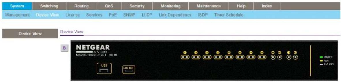
- To display the back view, click the B button.
The B button changes into the F button. (Clicking the F button displays the front view again.)
As an example, the following gure shows the back view of model M4250-10G2F-PoE+.

The port coloring indicates the port status:
- Black. The port is not connected to a device or disabled.
- Green. The port is connected to a device or enabled.
• Red. An error occurred on the port.
The system LEDs indicate the system status:
- To display the menus that let you congregate ports, right-click a port.
AV Line of Fully Managed Switches M4250 Series Main User Manual
As an example, the following gure shows the back view of model M4250-10G2F-PoE+ with a partial view of the menus that let you congure a port.

- To display the menus that let you congregate global switch settings, right-click the back view anywhere other than on a port.
As an example, the following gure shows the back view of model M4250-10G2F-PoE+ with menus that let you congure global switch settings.

Set up SNMP access
The switch software supports the conguration of SNMP groups and users that can manage traps that the SNMP agent generates.
The switch uses both standard public MIBs for standard functionality and private MIBs that support additional switch functionality. All private MIBs begin with a "-" prex. The main object for interface conguration is in -SWITCHING-MIB, which is a private MIB. Some interface congurations also involve objects in the public MIB, IF-MIB.
SNMP is enabled by default. The System Information page, which is the page that displays when you log in, displays the information that you need to congregate an SNMP manager to access the switch.
Any user can connect to the switch using the SNMP v3 protocol, but for authentication and encryption, the switch supports only one user, which is the admin user; therefore, only one prole can be created or modified.
You cannot access the switch using SNMPv3 until you log in to the switch as an admin and change the default password (see Log in to the main UI with a web browser on page 26). After you do, SNMPv3 is automatically configured with the MD5 authentication protocol and the new password for admin user.
For SNMPv3 switch access, the authentication protocol must be MD5 or SHA. You cannot use the "none" option for the authentication protocol.
For more information about SNMP, see Simple Network Management Protocol on page 152.
To configure authentication and encryption settings for the SNMPv3 admin profile:
- Launch a web browser.
- In the address eld of your web browser, enter the IP address of the switch. The login page displays.
- Click the Main UI Login button.
The main UI login page displays in a new tab.
- Enter admin as the user name, enter your local device password, and click the Login button.
The rst time that you log in, no password is required. However, you then must specify a local device password to use each subsequent time that you log in. The System Information page displays.
- Select System > SNMP > SNMP v3 User Conguration.
The User Conguration page displays.
- To enable authentication, select an Authentication Protocol option, which is either MD5 or SHA.
- To enable encryption, select the DES option in the Encryption Protocol list Then enter an encryption code of eight or more alphanumeric characters in the Encryption Key eld.
AV Line of Fully Managed Switches M4250 Series Main User Manual
- Click the Apply button.
Your settings are saved.
- To save the settings to the running conguration, click the Save icon.
Note: To access conguration information for SNMP V1 or SNMP V2, select System > SNMP > SNMPv1/v2 and select the page that contains the information that you want to congure.
2
Congure Switch System Information
This chapter covers the following topics:
- Switch system information
- Loopback interface
• IPv4 management interfaces and VLANs
• IPv6 management interfaces and VLANs
• Time and SNTP settings - Precision Time Protocol
- Domain Name System
- Switch database management template
- Green Ethernet settings
- Bonjour settings
- IPv4 DHCP server
• DHCP relay and relay statistics - DHCP Layer 2 relay
- UDP relay
- DHCPv6 server
- DHCPv6 relay interface
• Power over Ethernet - Timer schedules
- Simple Network Management Protocol
- Link Layer Discovery Protocol
- Link Layer Discovery Protocol for Media Endpoint Devices
- Link dependency
• Industry Standard Discovery Protocol
Switch system information
You can view and congregate the switch system information.
View and congure switch system information
When you log in, the System Information page displays. You can congregate and view general device information.
To view and dene system information:
- Launch a web browser.
-
In the address eld of your web browser, enter the IP address of the switch. The login page displays.
-
Click the Main UI Login button. The main UI login page displays in a new tab.
-
Enter admin as the user name, enter your local device password, and click the Login button. The rst time that you log in, no password is required. However, you then must specify a local device password to use each subsequent time that you log in. The System Information page displays.
5. Select System > Management > System Information.

6. Dene the following elds:
- System Name: Enter the name to identify this switch. You can use up to 255 alphanumeric characters. The factory default is blank.
- System Location: Enter the location of this switch. You can use up to 255 alphanumeric characters. The factory default is blank.
- System Contact: Enter the contact person for this switch. You can use up to 255 alphanumeric characters. The factory default is blank.
- Login Timeout: Specify how many minutes of inactivity can occur on a serial port connection before the switch closes the connection. Enter a number between 0 and 160 minutes. The factory default is 5. Entering 0 disables the time-out.
-
Management Source Interface: Select the management interface that is used as source interface for SNMP trap, syslog, DNS, TACACS+, RADIUS, sow, and SNTP applications. Possible values are as follows:
-
None
- Routing Interface
-
Routing VLAN
-
Routing Loopback Interface
- Service Port
- Different. For some applications from the list, the source interface is configured separately. They display in the list only if this is the case.
By default VLAN 1 is used as the source interface.
- Click the Apply button.
Your settings are saved.
- To save the settings to the running conguration, click the Save icon.
The following table describes the status information in the Application Information and System Information sections on the page.
Table 4. Application Information and System Information
| DescriptionField | |
| Application Information | |
| App Name | The name of the application that functions as the Universal Plug and Play (UPnP) agent. |
| The status of the application.App Status | |
| The version of the application.Version | |
| System Information | |
| The product name of this switch.Product Name | |
| The IPv4 address and mask assigned to the management VLAN interface.IPv4 Manage | |
| The IPv6 address and mask assigned to the management VLAN interface.IPv6 Manage | |
| IPv4 Management Interface | The IPv4 management VLAN ID of the switch. Click the displayed Management VLAN ID value to jump to the conguration page. See Congure an IPv4 management VLAN on page 50. |
| IPv6 Management Interface | The IPv6 management VLAN ID of the switch. Click the displayed Management VLAN ID value to jump to the conguration page. See Congure an IPv6 management VLAN on page 58. |
| The IPv4 address and mask assigned to the loopback interface.IPv4 Loopback Interfa | |
| The IPv6 prex and prex length assigned to the loopback interface.IPv6 Loopback Int | |
| The current date.System Date | |
| The time in days, hours, and minutes since the switch was restarted.System Up Tim | |
Table 4. Application Information and System Information (Continued)
| DescriptionField | |
| The current SNTP sync status.Current SNTP Sync Status | |
| The base object ID for the switch's enterprise MIB.System SNMP OID | |
| Universally assigned network address.System Mac Address | |
| The SNTP synchronized time.Current SNTP Synchronized Time |
View the fan status
This page shows the status of the fans in all units. These fans remove the heat genera by the power, CP,U and other chipsets, and allow the chipsets work normally. Fan status can be one of three possible values: OK, Failure, or Not Present.
To view the fan status:
-
Launch a web browser.
-
In the address eld of your web browser, enter the IP address of the switch. The login page displays.
-
Click the Main UI Login button. The main UI login page displays in a new tab.
-
Enter admin as the user name, enter your local device password, and click the Login button. The rst time that you log in, no password is required. However, you then must specify a local device password to use each subsequent time that you log in. The System Information page displays.
-
Scroll down to the Fan Status section.
- To refresh the page, click the Refresh button. The following table describes the noncongorable Fan Status information.
Table 5. Fan Status
| DescriptionField |
| The working status of the system fan 1.FAN-1 |
| The working status of the system fan 2.FAN-2 |
View the temperature sensor information
You can view the current temperature of different system sensors using the Temperature Status table.
To view temperature information:
- Launch a web browser.
- In the address eld of your web browser, enter the IP address of the switch.
The login page displays. - Click the Main UI Login button.
The main UI login page displays in a new tab. - Enter admin as the user name, enter your local device password, and click the Login button.
The rst time that you log in, no password is required. However, you then must specify a local device password to use each subsequent time that you log in.
The System Information page displays. - Scroll down to the Temperature Status section.
- To refresh the page, click the Refresh button.
The following table describes the noncongorable Temperature Status information.
Table 6. Temperature Status information
| DescriptionField |
| The current temperature in degrees Centigrade.sensor-1 |
| The maximum supported operating temperature in degrees Centigrade.Max Opera |
View the device status and rmware version
You can view the device status and rmware version.
To view the device status and rmware version:
- Launch a web browser.
-
In the address eld of your web browser, enter the IP address of the switch. The login page displays.
-
Click the Main UI Login button. The main UI login page displays in a new tab.
-
Enter admin as the user name, enter your local device password, and click the Login button. The rst time that you log in, no password is required. However, you then must specify a local device password to use each subsequent time that you log in. The System Information page displays.
-
Scroll down to the Temperature Status section.
- To refresh the page, click the Refresh button. The following table describes the noncongorable Device Status information.
Table 7. Device Status
| DescriptionField | |
| Firmware Version | The release.version.maintenance number of the code currently running on the switch. For example, if the release is 1, the version is2, and the maintenance number is 4, the format is 1.2.4. |
| Boot Version | The version of the boot code that is in the ash memory to load the rmware into the memory.The version of the software for CPLD.CPLD Version |
| The serial number of this switch.Serial Number | |
| PS-1 | Indicates the status of the power supply in the switch.The status can be any of the following:Operational: The power supply is present and functioning properly.Failed: The power supply is present, but the power cable is not plugged in or a bad cable is plugged in. |
| MAX PoE | Indicates the PoE system status on the switch:ON: Less than 10W of PoE power is available for another PD.OFF: At least 10W of PoE power available for another PD.N/A: PoE is not supported by the switch. |
| The time in days, hours, and minutes since the switch was restarted.System Up 1 |
View the system CPU status
To view the system CPU status:
- Launch a web browser.
- In the address eld of your web browser, enter the IP address of the switch. The login page displays.
-
Click the Main UI Login button. The main UI login page displays in a new tab.
-
Enter admin as the user name, enter your local device password, and click the Login button. The rst time that you log in, no password is required. However, you then must specify a local device password to use each subsequent time that you log in. The System Information page displays.
-
Select System > Management > System CPU Status. The System CPU Status page displays.
The CPU memory status includes the total memory of the switch in KBytes and the available memory space for the switch in KBytes.
The CPU utilization shows the CPU utilization by the various processes on the switch
Congure the CPU thresholds
You to congregate CPU thresholds that, when crossed, trigger a notification. The notification occurs through SNMP trap and syslog messages.
To congregate the CPU thresholds:
- Launch a web browser.
- In the address eld of your web browser, enter the IP address of the switch. The login page displays.
- Click the Main UI Login button.
The main UI login page displays in a new tab.
- Enter admin as the user name, enter your local device password, and click the Login button.
The rst time that you log in, no password is required. However, you then must specify a local device password to use each subsequent time that you log in.
The System Information page displays.
- Select System > Management > System CPU Status > CPU Threshold.
The CPU Threshold page displays.
-
Congure the following CPU threshold settings:
-
Rising Threshold: Configure the rising threshold value. A notification is generated when the total CPU utilization exceeds this threshold value over the congured time period. The range is a percentage from 1 to 100.
- Rising Interval: Congure the rising interval value. Congure this utilization monitoring time period from 5 to 86400 seconds in multiples of 5 seconds.
- Falling Threshold: Congure the falling threshold. A notification is triggered when the total CPU utilization falls below this level for a congured period of time. The falling utilization threshold must be equal to or less than the rising threshold value. The falling utilization threshold notification is generated only if a rising threshold notification was generated previously. Configuring the falling utilization threshold and time period is optional. If the falling CPU utilization values are not configured, they take the same value as the rising CPU utilization values. The range is a percentage from 1 to 100.
- Falling Interval: Congure the falling interval. YOu can congregate the utilization monitoring time period from 5 seconds to 86400 seconds in multiples of 5 seconds.
- Free Memory Threshold: Congure the CPU free memory threshold value in KB.
- Click the Apply button.
Your settings are saved.
- To save the settings to the running conguration, click the Save icon.
View or clear switch statistics
To view or clear the switch statistics:
- Launch a web browser.
-
In the address eld of your web browser, enter the IP address of the switch. The login page displays.
-
Click the Main UI Login button.
The main UI login page displays in a new tab.
- Enter admin as the user name, enter your local device password, and click the Login button.
The rst time that you log in, no password is required. However, you then must specify a local device password to use each subsequent time that you log in.
The System Information page displays.
- Select System > Management > Switch Statistics.
The Switch Statistics page displays.
- To clear all the counters, resetting all switch summary and detailed statistics to default values, click the Clear button.
The discarded packets count cannot be cleared.
- To save the settings to the running conguration, click the Save icon.
The following table describes switch statistics information.
Table 8. Switch statistics information
| DescriptionField | |
| ifIndex | The ifIndex of the interface table entry associated with the processor of this switch. |
| Octets Received | The total number of octets of data received by the processor (excluding framing bits but including FCS octets). |
Table 8. Switch statistics information (Continued)
| DescriptionField | |
| Packets Received Without Errors | The total number of packets (including broadcast packets and multicast packets) received by the processor. |
| Unicast Packets Received | The number of subnetwork-unicast packets delivered to a higher-layer protocol. |
| Multicast Packets Received | The total number of packets received that were directed to a multicast address. This number does not include packets directed to the broadcast address. |
| Broadcast Packets Received | The total number of packets received that were directed to the broadcast address. This does not include multicast packets. |
| Receive Packets Discarded | The number of inbound packets that were discarded even though no errors were detected to prevent their being deliverable to a higher-layer protocol. A possible reason for discarding a packet could be to free up buffer space. |
| Octets Transmitted | The total number of octets transmitted out of the interface, including framing characters. |
| The total number of packets transmitted out of the interface.Packets Transmitted V | |
| Unicast Packets Transmitted | The total number of packets that higher-level protocols requested that are transmitted to a subnetwork-unicast address, including those that were discarded or not sent. |
| Multicast Packets Transmitted | The total number of packets that higher-level protocols requested that are transmitted to a multicast address, including those that were discarded or not sent. |
| Broadcast Packets Transmitted | The total number of packets that higher-level protocols requested that are transmitted to the broadcast address, including those that were discarded or not sent. |
| Transmit Packets Discarded | The number of outbound packets that were discarded even though no errors were detected to prevent their being deliverable to a higher-layer protocol. A possible reason for discarding a packet could be to free up buffer space. |
| Most Address Entries Ever Used | The highest number of Forwarding Database Address Table entries learned by this switch since the most recent reboot. |
| Address Entries in Use | The number of learned and static entries in the Forwarding Database Address Table for this switch. |
| The maximum number of virtual LANs (VLANs) allowed on this switch.Maximum VL | |
| Most VLAN Entries Ever Used | The largest number of VLANs that were active on this switch since the last reboot. |
| Static VLAN Entries | The number of presently active VLAN entries on this switch that were created statically. |
| Dynamic VLAN Entries | The number of presently active VLAN entries on this switch that were created by GVRP registration. |
| VLAN Deletes | The number of VLANs on this switch that were created and then deleted since the last reboot. |
| Time Since Counters Last Cleared | The elapsed time, in days, hours, minutes, and seconds, since the statistics for this switch were last cleared. |
View USB device information
To display the USB device information:
- Launch a web browser.
-
In the address eld of your web browser, enter the IP address of the switch. The login page displays.
-
Click the Main UI Login button. The main UI login page displays in a new tab.
-
Enter admin as the user name, enter your local device password, and click the Login button. The rst time that you log in, no password is required. However, you then must specify a local device password to use each subsequent time that you log in. The System Information page displays.
-
Select System > Management > USB Device Information.
The USB Device Information page displays.
The Device Status eld displays the current status of the device. The status is one of the following:
• Active: The device is USB plugged in and recognized by the switch.
- Inactive: The device is not mounted.
- Invalid: The device is not present or an invalid device is plugged in.
- To refresh the page, click the Refresh button.
The following table describes the information in the USB Memory Statistics section.
Table 9. USB Memory Statistics information
| DescriptionField |
| The USB ash device storage size in bytes.Total Size |
| The size of memory used on the USB ash device.Bytes Used |
| The size of memory free on the USB ash device.Bytes Free |
The following table describes the information in the USB Directory Details section.
Table 10. USB Directory Details information
| DescriptionField |
| The name of the le stored in the USB ash drive.File Name |
| The size of the le stored in the USB ash drive in bytesFile Size |
| The last modification time of the le stored in the USB ash drive.Modication Time |
Loopback interface
You can create, congure, and remove loopback interfaces.
To congregate a loopback interface:
- Launch a web browser.
- In the address eld of your web browser, enter the IP address of the switch. The login page displays.
-
Click the Main UI Login button. The main UI login page displays in a new tab.
-
Enter admin as the user name, enter your local device password, and click the Login button. The rst time that you log in, no password is required. However, you then must specify a local device password to use each subsequent time that you log in. The System Information page displays.
-
Select System > Management > Loopback Interface.
The Loopback Interface page displays.
- From the Loopback Interface Type menu, select IPv4 or IPv6.
- From the Loopback ID menu, select an interface.
- Congure the following settings, depending on the type of loopback interface:
- IPv4: For an IPv4 interface, congure the following settings:
- Primary IP Address: Enter the primary IPv4 address for this interface in dotted-decimal notation.
- Primary IP Subnet Mask: Enter the primary IPv4 subnet mask in dotted-decimal notation.
- IPv6: For an IPv6 interface, congure the following settings:
- IPv6 mode: Select Enable to use the IPv6 address after you specify it. You can select this option only before you specify the IPv6 address.
• IPv6 Prex: Enter the IPv6 prex. - Prex Length: Enter the length for the IPv6 prex.
-
EUI64: As an option, specify the 64-bit extended unique identifier (EUI-64).
-
Click the Apply button.
Your settings are saved.
- To save the settings to the running conguration, click the Save icon.
IPv4 management interfaces and VLANs
The main UI provides separate options for IPv4 interface and port-based IP management.
If you congregate port-based IP management, VLAN-based IP management is disabled. Similarly, if you congregate VLAN-based IP management, port-based IP management is disabled.
By default, the source interface for applications is VLAN 1. If you change the IPv4 management VLAN and port to a non-default value, the source interface to the VLAN 1 default VLAN and port are also automatically changed.
You can access the switch over the main UI by one of the following methods:
- IPv4 service port: The service port is a dedicated Ethernet port for out-of-band (OOB) management of the switch. Trafc on this port is segregated from operational
network traffic on the switch ports and cannot be switched or routed to the operational network.
- Management VLAN interface: The management VLAN is the logical interface used for in-band connectivity with the switch over any of the switch's network interfaces. To access the switch over a network you must first configure an IP address and submask for the switch.
- Optional single management interface: By default, you can use any of the switch's network interfaces as the management interface. However, you can restrict IPv4 management to one specific network interface.
Congure the IPv4 service port
You can congregate network information on the IPv4 service port, also referred to as the out-of-band (OOB) port. The service port is a dedicated Ethernet port for out-of-band management of the switch. Trafc on this port is segregated from operational network trafc on the switch ports and cannot be switched or routed to the operational network.
By default, no IP address is set for the OOB port, but its DHCP client is enabled so that the port can receive an IP address from a DHCP server in your network. If the OOB port does not receive an IP address from a DHCP server in your network, the IP address for the port is set to 192.168.0.239 with 255.255.255.0 as the subnet mask. The same occurs if you connect the OOB port directly to a computer and reboot the switch.
To congregate the IPv4 service port:
- Launch a web browser.
-
In the address eld of your web browser, enter the IP address of the switch. The login page displays.
-
Click the Main UI Login button. The main UI login page displays in a new tab.
-
Enter admin as the user name, enter your local device password, and click the Login button. The rst time that you log in, no password is required. However, you then must specify a local device password to use each subsequent time that you log in. The System Information page displays.
-
Select System > Management > Management Interfaces > IPv4 Service Port Conguration. The IPv4 Service Port Conguration page displays.
-
Select a Service Port Conguration Protocol radio button:
-
Bootp: During the next boot cycle, the BootP client on the device broadcasts a BootP request to acquire information from a BootP server on the network. The IP Address, Subnet Mask, and Default Gateway eld display the information is dynamically acquired.
- DHCP: During the next boot cycle, the DHCP client on the device broadcasts a DHCP request to acquire information from a DHCP server on the network. The IP Address, Subnet Mask, and Default Gateway eld display the information is dynamically acquired.
- None: The device does not attempt to acquire network information dynamically. You must congregate the address settings manually:
- IP Address: Specify the IP address of the interface.
- Subnet Mask: Specify the IP subnet mask for the interface.
- Default Gateway: Specify the default gateway for the IP interface.
7. Click the Apply button.
Your settings are saved.
8. To save the settings to the running conguration, click the Save icon.
The following table describes the noncongorable elds on the page.
Table 11. IPv4 service port conguration information
| DescriptionField |
| The burned-in MAC address used for out-of-band connectivity.Burned-in MAC Address |
| Indicates whether the link status is up or down.Interface Status |
| If the selection is DHCP, the DHCP client ID.DHCP Client Identier |
Congure an IPv4 management VLAN
For you to manage the switch over the main UI, you must denote the management IP address. A management VLAN interface is created by default and it gets an IP address if a DHCP server is present. If the management VLAN interface cannot get an IP address the automatically assigned fallback IPv4 address is 169.254.100.100 and the subnet mask is 255.255.0.0.
A management VLAN is used as the default source interface for the syslog, the message log, an SNMP client, and so on. The network interface is disabled by default.
The management VLAN is the logical interface used for in-band connectivity with the switch through any of the switch's front panel ports. The conguration parameters
associated with the switch's management VLAN do not affect the conguration of the front panel ports through which trafc is switched or routed.
To access the switch over a network you must rst conjure an IP address and subnet mask for the switch. You can conjure the IP information using any of the following:
- DHCP
• Terminal interface through the EIA-232 port
After you establish in-band connectivity, you can change the IP information using any of the following:
• Terminal interface through the EIA-232 port
• Terminal interface through Telnet
• SNMP-based management
• Web-based management
To congregate an IPv4 management VLAN or reset the IPv4 management VLAN:
- Launch a web browser.
-
In the address eld of your web browser, enter the IP address of the switch. The login page displays.
-
Click the Main UI Login button. The main UI login page displays in a new tab.
-
Enter admin as the user name, enter your local device password, and click the Login button. The rst time that you log in, no password is required. However, you then must specify a local device password to use each subsequent time that you log in. The System Information page displays.
-
Select System > Management > Management Interfaces > IPv4 Management VLAN Conguration. The IPv4 Management VLAN Conguration page displays.
-
In the Management VLAN ID eld, specify the management VLAN ID of the switch. The IPv4 management VLAN is used for management of the switch. You can configure any value in the range of 1 to 4093.
-
Select the Enable or Disable Routing Mode radio button to enable or disable global routing on the switch. The default value is Enable.
-
Select the Configuration Method DHCP or Manual radio button to specify the switch startup action:
-
DHCP: The switch requests IP address information from a DHCP server.
-
Manual: The switch loads the IP address information that you specify:
-
IP Address: Specify the IP address of the interface. The default value is 169.254.100.100.
- Subnet Mask: Specify the IP subnet mask for the interface. This is also referred to as the subnet/network mask and denes the portion of the interface's IP address that is used to identify the attached network. The default value is 255.255.0.0.
-
Gateway: Specify the gateway for the interface. The default value is 0.0.0.0.
-
Click the Apply button.
Your settings are saved.
- To save the settings to the running conguration, click the Save icon.
Note: If you need to reset the IPv4 management VLAN, in the Reset IPv4 Management Interface section of the page, select the Set Management Interface to Default check box and click the Apply button. Doing so deletes the port-based IPv4 management interface conguration and sets the IPv4 management interface back to the default VLAN 1.
The Current IPv4 Management Interface Status section displays the following noncongorable elds.
Table 12. Noncongorable IPv4 management interface status information
| DescriptionField | |
| Displays the current IPv4 management VLAN.Management Interface | |
| Indicates whether the link status is up or down.Link State | |
| Routing Interface Status | Indicates whether the link status is up or down for the management interface. |
| The MAC address assigned to the management interface.MAC Address | |
| IP Address Configuration Method | Indicates whether the IP address configuration method is DHCP or manual. |
| The IP address of the management interface.IP Address |
Table 12. Noncongorable IPv4 management interface status information (Continued)
| DescriptionField |
| The IP subnet mask for the management interface.Subnet Mask |
| The specied default gateway for the management interface.Gateway |
Congure an IPv4 management interface
You can restrict IPv4 management to one specific interface. By default, you can use any of the interfaces as an IPv4 management interface.
To congregate an IPv4 management interface:
- Launch a web browser.
-
In the address eld of your web browser, enter the IP address of the switch. The login page displays.
-
Click the Main UI Login button. The main UI login page displays in a new tab.
-
Enter admin as the user name, enter your local device password, and click the Login button. The rst time that you log in, no password is required. However, you then must specify a local device password to use each subsequent time that you log in. The System Information page displays.
-
Select System > Management > Management Interfaces > IPv4 Management Interface Conguration. The IPv4 Management Interface Conguration page displays.
-
From the Interface menu, select the interface that must become the IPv4 management interface.
-
Select the Set Management Interface option check box so that you can congregate the interface IP address settings
-
Select a Conguration Method radio button:
-
DHCP: The switch obtains the management interface IP address settings from a DHCP server in the network.
- Manual: Congure the management interface IP address settings manually:
- IP Address: Specify the IP address for the management interface. The default IP address is 169.254.100.100.
- Subnet Mask: Specify the subnet mask for the management interface. The default subnet mask is 255.255.0.0.
-
Gateway: Specify the IP address of the default gateway for the management interface. The default IP address is 0.0.0.0.
-
Click the Apply button.
Your settings are saved.
- To save the settings to the running conguration, click the Save icon.
Note: If you need to reset the IPv4 management interface, in the Reset IPv4 Manager Interface section of the page, select the Set Management Interface to Default check box and click the Apply button. Doing so deletes the IPv4 management interface conguration and sets the IPv4 management interface back to the default setting.
The Current IPv4 Management Interface section displays the following noncongorable elds.
Table 13. Noncongorable IPv4 management interface status information
| DescriptionField | |
| Displays the current IPv4 management interfaceManagement Interface | |
| Indicates whether the link status is up or down.Link State | |
| Routing Interface Status | Indicates whether the link status is up or down for the management interface. |
| The MAC address assigned to the management interface.MAC Address | |
| IP Address Configuration Method | Indicates whether the IP address configuration method is DHCP or manual. |
| The IP address of the management interface.IP Address |
Table 13. Noncongorable IPv4 management interface status information (Continued)
| DescriptionField |
| The IP subnet mask for the management interface.Subnet Mask |
| The specied default gateway for the management interface.Gateway |
IPv6 management interfaces and VLANs
The main UI provides separate options for IPv6 interface and port-based IP management.
If you congregate port-based IP management, VLAN-based IP management is disabled. Similarly, if you congregate VLAN-based IP management, port-based IP management is disabled.
By default, the source interface for applications is VLAN 1. If you change the IPv6 management VLAN and port to a non-default value, the source interface to the VLAN 1 default VLAN and port are also automatically changed.
You can access the switch over the main UI by one of the following methods:
- IPv6 service port: The service port is a dedicated Ethernet port for out-of-band management of the switch. Traffic on this port is segregated from operational network traffic on the switch ports and cannot be switched or routed to the operational network.
- Management VLAN interface: The management VLAN is the logical interface used for in-band connectivity with the switch over any of the switch's network interfaces. To access the switch over a network you must first configure an IP address and submask for the switch. To congregate an IPv6 management VLAN, you can either use the same VLAN that is used for IPv4 management or a different VLAN. The switch does not provide a default IPv6 management VLAN. If you want to use one, you create it manually.
- Optional single management interface: By default, you can use any of the switch's network interfaces as the management interface. However, you can restrict IPv6 management to one specific network interface.
Congure an IPv6 service port
You can congregate IPv6 network information on the service port. The service port is a dedicated Ethernet port for out-of-band management of the switch Trafc on this port is segregated from operational network traffic on the switch ports and cannot be switched or routed to the operational network.
To congregate the IPv6 service port:
- Launch a web browser.
-
In the address eld of your web browser, enter the IP address of the switch. The login page displays.
-
Click the Main UI Login button. The main UI login page displays in a new tab.
-
Enter admin as the user name, enter your local device password, and click the Login button. The rst time that you log in, no password is required. However, you then must specify a local device password to use each subsequent time that you log in. The System Information page displays.
-
Select System > Management > Management Interfaces > IPv6 Service Port Conguration. The IPv6 Service Port Conguration page displays.
-
Select the IPv6 mode Enable or Disable radio button. This species the IPv6 administrative mode on the service port.
-
Select the Service Port Conguration Protocol None or DHCP radio button. This species whether the device acquires network information from a DHCPv6 server. Selecting None disables the DHCPv6 client on the service port. If you select the DHCP radio button, the DHCPv6 Client DUID field displays the client identifier used by the DHCPv6 client when sending messages to the DHCPv6 server.
-
Select the IPv6 Stateless Address AutoConfig mode Enable or Disable radio button:
-
Enable: The service port can acquire an IPv6 address through IPv6 Neighbor Discovery Protocol (NDP) and through the use of router advertisement messages.
- Disable: The service port does not use the native IPv6 address autoconguration feature to acquire an IPv6 address.
This sets the IPv6 stateless address autoconguration mode on the service port.
- To congregate the IPv6 gateway, do the following:
a. select the Change IPv6 Gateway check box. The IPv6 gateway is the default gateway for the IPv6 service port interface.
b. In the IPv6 Gateway eld, specify the default gateway for the IPv6 service port interface.
- Click the Apply button.
Your settings are saved.
- To save the settings to the running conguration, click the Save icon.
Manage IPv6 addresses for the IPv6 service port
You can add a static IPv6 address that is specific to the IPv6 service port. You can also remove an IPv6 address that you no longer need for the IPv6 service port.
To add or remove an IPv6 address for the IPv6 service port:
- Launch a web browser.
-
In the address eld of your web browser, enter the IP address of the switch. The login page displays.
-
Click the Main UI Login button. The main UI login page displays in a new tab.
-
Enter admin as the user name, enter your local device password, and click the Login button. The rst time that you log in, no password is required. However, you then must specify a local device password to use each subsequent time that you log in. The System Information page displays.
-
Select System > Management > Management Interfaces > IPv6 Service Port Conguration. The IPv6 Service Port Conguration page displays.
The Add/Delete IPv6 Address table lists the static IPv6 addresses that you manually added to the service port interface.
-
To add an IPv6 address, in the Add/Delete IPv6 Address section, do the following:
a. In the IPv6 Address eld, specify the IPv6 address that you want to add.
b. From the EUI FLAG menu, select True to enable the Extended Universal Identifier (EUI) ag for the IPv6 address, or select False to omit the ag.
c. Click the Add button. The IPv6 address is added to the IPv6 service port. -
To remove an IPv6 address, in the Add/Delete IPv6 Address section, do the following:
a. Select the check box for the IPv6 address that you want to remove.
b. Click the Delete button.
The IPv6 address is removed from the IPv6 service port.
- To save the settings to the running conguration, click the Save icon.
Congure an IPv6 management VLAN
For you to manage the switch over the main UI, you must denote the management IP address. A management VLAN interface is created by default and it gets an IP address if a DHCP server is present. If the management VLAN interface cannot get an IP address the automatically assigned fallback IPv4 address is 169.254.100.100 and the subnet mask is 255.255.0.0.
A management VLAN is used as the default source interface for the syslog, the message log, an SNMP client, and so on. The network interface is disabled by default.
The management VLAN is the logical interface used for in-band connectivity with the switch through any of the switch's front panel ports. The conguration parameters associated with the switch's management VLAN do not affect the conguration of the front panel ports through which trafc is switched or routed.
To access the switch over a network you must rst conjure an IP address and subnet mask for the switch. You can conjure the IP information using any of the following:
- DHCP
• Terminal interface through the EIA-232 port
After you establish in-band connectivity, you can change the IP information using any of the following:
• Terminal interface through the EIA-232 port
• Terminal interface through Telnet
• SNMP-based management
• Web-based management
To congregate an IPv6 management VLAN, you can either use the same VLAN that is used for IPv4 management or a different VLAN. The switch does not provide a default IPv6 management VLAN. If you want to use one, you must create it manually.
To congregate an IPv6 management VLAN or reset the IPv6 management VLAN:
- Launch a web browser.
- In the address eld of your web browser, enter the IP address of the switch. The login page displays.
- Click the Main UI Login button.
AV Line of Fully Managed Switches M4250 Series Main User Manual
The main UI login page displays in a new tab.
- Enter admin as the user name, enter your local device password, and click the Login button.
The rst time that you log in, no password is required. However, you then must specify a local device password to use each subsequent time that you log in.
The System Information page displays.
- Select System > Management > Management Interfaces > IPv6 Management VLAN Conguration.
The IPv6 Management VLAN Conguration page displays.
- In the Management VLAN ID eld, specify the management VLAN ID of the switch. The IPv6 management VLAN is used for management of the switch. You can configure any value in the range of 1 to 4093.
- Select the IPv6 Enable Mode Enable or Disable radio button to specify he administration mode for the IPv6 management VLAN.
- Select the Address Autocongure Mode Enable or Disable radio button to specify the address autoconguration mode.
If you enable this mode, the IPv6 network settings (IPv6 prex and prex length) are automatically configured for the configured management VLAN interface. By default, for VLAN 1, the mode is enabled so that the settings are automatically congured.
Note: The Address Autocongure mode option is available only if unicast routing is globally disabled.
- Select the Address DHCP Mode Enable or Disable radio button to specify if the IPv6 settings are obtained from a DHCP server.
- Click the Apply button.
Your settings are saved.
- To save the settings to the running conguration, click the Save icon.
Note: If you need to reset the IPv6 management interface, in the Reset IPv6 Manager Interface section of the page, select the Set Management Interface to Default check box and click the Apply button. Doing so deletes the IPv6 management interface conguration.
The Current IPv6 Management Interface Status section displays the following noncongorable elds.
Table 14. Current IPv6 management interface status information
| DescriptionField | |
| Management Interface | The IPv6 management interface. (By default, no IPv6 management interface is congured). |
| Indicates if the link status is up or down.Link State | |
| IPv6 Routing Interface Status/Operational Mode | Indicates if the link status is up or down for the IPv6 management interface. |
| The MAC address that is assigned to the IPv6 management interface.MAC Address | |
| Indicates if IPv6 is enabled or disabled on the IPv6 management interface.IPv6 Enable | |
| IPv6 Routing Mode | Indicates if IPv6 routing is enabled or disabled on the IPv6 management interface. |
| Stateless Address Autocong Mode | Indicates if the IPv6 address autoconguration mode is enabled or disabled on the IPv6 management interface. |
| DHCPv6 Client Mode | Indicates if the DHCPv6 Client Mode is enabled or disabled on the IPv6 management interface. |
| The IPv6 address of the default gateway of the switch.IPv6 Default Gateway | |
| The IPv6 address of the next hop interface of the switch.IPv6 Next Hop Interface | |
| IPv6 Prex/Prex Length | The IPv6 prex and prex length that is used for the IPv6 management interface. |
| The EUI-64 ag of the IPv6 address on the IPv6 management interface.EU164 | |
| The current state of the IPv6 address on the IPv6 management interface.Current State |
Manage IPv6 addresses for the IPv6 management VLAN
You can add a static IPv6 address that is specific to the IPv6 management VLAN. You can also remove an IPv6 address that you no longer need for the IPv6 management VLAN.
To add or remove an IPv6 address for the IPv6 management VLAN:
- Launch a web browser.
- In the address eld of your web browser, enter the IP address of the switch.
The login page displays. -
Click the Main UI Login button.
The main UI login page displays in a new tab. -
Enter admin as the user name, enter your local device password, and click the Login button.
The rst time that you log in, no password is required. However, you then must specify a local device password to use each subsequent time that you log in.
The System Information page displays.
- Select System > Management > Management Interfaces > IPv6 Management VLAN Conguration.
The IPv6 Management VLAN Conguration page displays.
If the Address Autocongure Mode is enabled, the autocongured IPv6 prex and prex length are displayed in the IPv6 VLAN Interface Conguration section.
- To add an IPv6 address, in the IPv6 VLAN Interface Conguration section, do the following:
a. In the IPv6 Prex/Prex Length eld, specify the IPv6 address and prex length that you want to add.
b. From the EUI64 menu, select True to enable the Extended Universal Identifier (EUI) ag for the IPv6 address, or select False to omit the ag.
c. Click the Add button.
The IPv6 address is added to the IPv6 management VLAN.
- To remove an IPv6 address, in the IPv6 VLAN Interface Conguration section, do the following:
a. Select the check box for the IP address and prex that you want to remove.
b. Click the Delete button.
The IPv6 address is removed from the IPv6 management VLAN.
- To save the settings to the running conguration, click the Save icon.
Manage the IPv6 default route addresses for the IPv6 management VLAN
You can add an IPv6 default route address that is specific to the IPv6 management VLA. You can also remove an IPv6 default route address that you no longer need for the IF management VLAN.
To add or remove an IPv6 default route address for the IPv6 management VLAN:
-
Launch a web browser.
-
In the address eld of your web browser, enter the IP address of the switch.
The login page displays.
- Click the Main UI Login button.
The main UI login page displays in a new tab.
- Enter admin as the user name, enter your local device password, and click the Login button.
The rst time that you log in, no password is required. However, you then must specify a local device password to use each subsequent time that you log in.
The System Information page displays.
- Select System > Management > Management Interfaces > IPv6 Management VLAN Conguration.
The IPv6 Management VLAN Conguration page displays.
- To add an IPv6 default route address, in the IPv6 Default Route Configuration section, do the following:
a. Select the Change IPv6 Default Route check box.
b. In the IPv6 Default Route Address eld, specify the IPv6 address and prex length that you want to add.
c. Click the Add button.
The IPv6 default route address is added to the IPv6 management VLAN.
- To remove an IPv6 default route address, in the IPv6 Default Route Conguration section, do the following:
a. Select the check box for the IPv6 default route address that you want to remove
b. Click the Delete button.
The IPv6 default route address is removed from the IPv6 management VLAN.
- To save the settings to the running conguration, click the Save icon.
Congure an IPv6 management interface
You can restrict IPv6 management to one specific interface. By default, you can use any of the interfaces as an IPv6 management interface.
To congure an IPv6 management interface:
-
Launch a web browser.
-
In the address eld of your web browser, enter the IP address of the switch. The login page displays.
-
Click the Main UI Login button.
The main UI login page displays in a new tab.
- Enter admin as the user name, enter your local device password, and click the Login button.
The rst time that you log in, no password is required. However, you then must specify a local device password to use each subsequent time that you log in.
The System Information page displays.
- Select System > Management > Management Interfaces > IPv6 Management Interface Conguration.
The IPv6 Management Interface Conguration page displays.
-
From the Interface menu, select the interface that must become the IPv6 management interface.
-
Select the Set Management Interface option check box so that you can congregate the interface settings.
-
Select the Routing Mode Enable or Disable radio button to enable or disable routing on the IPv6 management interface.
-
Select the IPv6 Enable Mode Enable or Disable radio button to enable or disable IPv6 on the IPv6 management interface.
-
Select the Stateless Address Autocongure Mode Enable or Disable radio button to enable or disable the on the IPv6 management interface.
You can enable this mode only if unicast routing is globally disabled.
-
Select the DHCPv6 Client Mode Enable or Disable radio button to enable or disable the DHCPv6 client mode on the IPv6 management interface.
-
Click the Apply button.
Your settings are saved.
- To save the settings to the running conguration, click the Save icon.
Note: If you need to reset the IPv6 management interface, in the Reset IPv6 Manager Interface section of the page, select the Set Management Interface to Default check box and click the Apply button. Doing so deletes the IPv6 management interface conguration.
The Current IPv6 Management Interface Status section displays the following noncongorable elds.
Table 15. Current IPv6 management interface status information
| DescriptionField | |
| Management Interface | The IPv6 management interface. (By default, no IPv6 management interface is congured). |
| Indicates if the link status is up or down.Link State | |
| IPv6 Routing Interface Status/Operational Mode | Indicates if the link status is up or down for the IPv6 management interface. |
| The MAC address that is assigned to the IPv6 management interface.MAC Address | |
| Indicates if IPv6 is enabled or disabled on the IPv6 management interface.IPv6 Enable | |
| IPv6 Routing Mode | Indicates if IPv6 routing is enabled or disabled on the IPv6 management interface. |
| Stateless Address Autocong Mode | Indicates if the IPv6 address autoconguration mode is enabled or disabled on the IPv6 management interface. |
| DHCPv6 Client Mode | Indicates if the DHCPv6 Client Mode is enabled or disabled on the IPv6 management interface. |
| The IPv6 address of the default gateway of the switch.IPv6 Default Gateway | |
| The IPv6 address of the next hop interface of the switch.IPv6 Next Hop Interface | |
| IPv6 Prex/Prex Length | The IPv6 prex and prex length that is used for the IPv6 management interface. |
| The EUI-64 ag of the IPv6 address on the IPv6 management interface.EU164 | |
| The current state of the IPv6 address on the IPv6 management interface.Current State |
Manage IPv6 addresses for the IPv6 management inter
You can add a static IPv6 address that is specific to the IPv6 management interface. You can also remove an IPv6 address that you no longer need for the IPv6 management interface.
To add or remove an IPv6 address for the IPv6 management interface:
- Launch a web browser.
- In the address eld of your web browser, enter the IP address of the switch.
The login page displays. -
Click the Main UI Login button.
The main UI login page displays in a new tab. -
Enter admin as the user name, enter your local device password, and click the Login button.
The rst time that you log in, no password is required. However, you then must specify a local device password to use each subsequent time that you log in.
The System Information page displays.
- Select System > Management > Management Interfaces > IPv6 Management Interface Conguration.
The IPv6 Management Interface Conguration page displays.
- To add an IPv6 address, in the IPv6 Management Interface Conguration section, do the following:
a. Select the Set Management Interface check box. It is likely that you already did this when you started the conguration of the IPv6 management interface.
b. In the IPv6 Prex eld, specify the IPv6 address that you want to add.
c. In the Prex Length eld, specify the prex length for the IPv6 address that you want to add.
d. From the EUI64 menu, select Enable to enable the Extended Universal Identier (EUI) ag for the IPv6 address, or select Disable to omit the ag.
e. Click the Add button. The IPv6 address is added to the IPv6 management interface.
- To remove an IPv6 address, in the IPv6 Management Interface Configuration section, do the following:
a. Select the check box for the IPv6 that you want to remove.
b. Click the Delete button.
The IPv6 address is removed from the IPv6 management interface.
- To save the settings to the running conguration, click the Save icon.
Manage the IPv6 default route addresses for the IPv6 management interface
You can add an IPv6 default route address that is specific to the IPv6 management interface. You can also remove an IPv6 default route address that you no longer need for the IPv6 management interface.
To add or remove an IPv6 default route address for the IPv6 management interface
- Launch a web browser.
- In the address eld of your web browser, enter the IP address of the switch.
The login page displays.
- Click the Main UI Login button.
The main UI login page displays in a new tab.
- Enter admin as the user name, enter your local device password, and click the Login button.
The rst time that you log in, no password is required. However, you then must specify a local device password to use each subsequent time that you log in.
The System Information page displays.
- Select System > Management > Management Interfaces > IPv6 Management Interface Conguration.
The IPv6 Management Interface Conguration page displays.
- To add an IPv6 default route address, in the IPv6 Default Route Configuration section, do the following:
a. Select the Change IPv6 Default Route check box.
b. In the IPv6 Default Route Address eld, specify the IPv6 address and prex length that you want to add.
c. Click the Add button.
The IPv6 default route address is added to the IPv6 management interface.
- To remove an IPv6 default route address, in the IPv6 Default Route Conguration section, do the following:
a. Select the check box for the IPv6 default route address that you want to remove
b. Click the Delete button.
The IPv6 default route address is removed from the IPv6 management interface.
- To save the settings to the running conguration, click the Save icon.
Time and SNTP settings
The switch supports the Simple Network Time Protocol (SNTP). As its name suggests, it is a less complicated version of Network Time Protocol (NTP), which is a system for
synchronizing the clocks of networked computer systems, primarily when data transfer is handled through the Internet. You can also set the system time manually.
Congure the time setting manually
To congregate the time setting manually
- Launch a web browser.
-
In the address eld of your web browser, enter the IP address of the switch. The login page displays.
-
Click the Main UI Login button. The main UI login page displays in a new tab.
-
Enter admin as the user name, enter your local device password, and click the Login button. The rst time that you log in, no password is required. However, you then must specify a local device password to use each subsequent time that you log in. The System Information page displays.
-
Select System > Management > Time > Time Conguration. The Time Conguration page displays.
-
Select the Clock Source Local radio button. The default is SNTP.
-
In the Date eld, specify the current date in months, days, and years.
- In the Time eld, specify the current time in hours, minutes, and seconds.
-
Click the Apply button. Your settings are saved.
-
To save the settings to the running conguration, click the Save icon.
Congure the time settings with SNTP and congregate the global SNTP settings
To congregate the time by using SNTP and congregate the global SNTP settings:
- Launch a web browser.
-
In the address eld of your web browser, enter the IP address of the switch. The login page displays.
-
Click the Main UI Login button.
The main UI login page displays in a new tab.
- Enter admin as the user name, enter your local device password, and click the Login button.
The rst time that you log in, no password is required. However, you then must specify a local device password to use each subsequent time that you log in.
The System Information page displays.
- Select System > Management > Time > Time Conguration.
The Time Conguration page displays.
- Select the Clock Source SNTP radio button.
The default is SNTP.
In the SNTP Global Configuration section of the page, configure the following settings.
- Select a Client mode radio button to specify the operation mode of the SNTP client on the switch:
- Disable: SNTP is not operational. No SNTP requests are sent from the client and no received SNTP messages are processed.
- Unicast: SNTP operates in a point-to-point mode. A unicast client sends a request to a designated server at its unicast address and expects a reply from which it can determine the time and, optionally, the round-trip delay and local clock offset relative to the server.
The default selection is Unicast. You can add the IP address or DNS name of one or more SNTP servers for the switch to poll. For more information, see Congure SNTP servers on page 72.
- Broadcast: SNTP operates uses a local broadcast address instead of a multicast address. The broadcast address has a single subnet scope while a multicast address has an Internet wide scope.
- In the Port eld, specify the local UDP port on which the SNTP client receives server packets.
The port number is 123 or in a range from 1025 to 65535. The default is 123. With the default value is congured, the actual client port value used in SNTP packets is assigned by the operating system.
- From the Source Interface menu, select the interface that the SNTP client must use:
- None: The primary IP address of the originating (outbound) interface is used as the source address.
- Routing interface: The primary IP address of a physical port is used as the source address.
AV Line of Fully Managed Switches M4250 Series Main User Manual
- Routing VLAN: The primary IP address of a VLAN routing interface is used as the source address.
- Routing loopback interface: The primary IP address of a routing loopback interface is used as the source address.
- Tunnel interface: The IPv6 tunnel interface.
- Service port: The management port source IP address is used as the source address.
By default VLAN 1 is used as the source interface.
- In the Unicast Poll Interval eld, specify the number of seconds between unicast poll requests expressed as a power of 2. to The range is from 6 to 10. The default 6.
- In the Broadcast Poll Interval eld, specify the number of seconds between broadcast poll requests expressed as a power of 2.
Broadcasts received prior to the expiry of this interval are discarded. The range is from 6 to 10. The default is 6.
- In the Unicast Poll Timeout eld, specify the number of seconds to wait for an SNT response to a unicast poll request.
The range is from 1 to 30. The default is 5.
- In the Unicast Poll Retry eld, specify the number of times to retry a unicast poll request to an SNTP server after the rst time-out before the switch attempts to use the next congured server.
The range is from 0 to 10. The default is 1.
- In the Time Zone Name eld, specify a time zone.
In the Offset Hours and Offset Minutes elds, you can also specify the number of hours and number of minutes that the time zone is different from the Coordinated Universal Time (UTC). The time zone can affect the display of the current system time.
Note: When you use an SNTP or NTP time server, the time data that is received from the server is based on the UTC, which is the same as Greenwich Mean Time (GMT). This might not be the time zone in which the switch is located.
- In the Offset Hours eld, specify the number of hours that the time zone is different from UTC.
The range is from -12 to 14. The default is 0.
- In the Offset Minutes eld, specify the number of minutes that the time zone is different from UTC.
The range is from 0 to 59. The default is 0.
- Click the Apply button.
Your settings are saved.
- To save the settings to the running conguration, click the Save icon.
View the SNTP global status
When you select the SNTP option as the clock source, you can view the SNTP global status.
To view SNTP global status:
- Launch a web browser.
-
In the address eld of your web browser, enter the IP address of the switch. The login page displays.
-
Click the Main UI Login button.
The main UI login page displays in a new tab.
- Enter admin as the user name, enter your local device password, and click the Login button.
The rst time that you log in, no password is required. However, you then must specify a local device password to use each subsequent time that you log in.
The System Information page displays.
- Select System > Management > Time > Time Conguration.
The Time Conguration page displays.
The SNTP Global Status section displays the following noncongorable elds:
Table 16. SNTP global status information
| DescriptionField | |
| The SNTP version that the client supports.Version | |
| Supported mode | The SNTP modes that the client supports. Multiple modes can be supported by a client. |
| The local date and time (UTC) that the SNTP client last updated the system clock.Last | |
| Last Attempt Time | The local date and time (UTC) of the last SNTP request or receipt of an unsolicited message. |
| Last Attempt Status | The status of the last SNTP request or unsolicited message for both unicast and broadcast modes. If no message was received from a server, a status of Other is displayed. These values are appropriate for all operational modes.Other: None of the following enumeration values.Success: The SNTP operation was successful and the system time was updated.Request Timed Out: A directed SNTP request timed out without receiving a response from the SNTP server.Bad Date Encoded: The time provided by the SNTP server is not valid.Version Not Supported: The SNTP version supported by the server is not compatible with the version supported by the client.Server Unsynchronized: The SNTP server is not synchronized with its peers. This is indicated through the leap indicator eld on the SNTP message.Server Kiss Of Death: The SNTP server indicated that no further queries were to be sent to this server. This is indicated by a stratum eld equal to 0 in a message received from a server. |
| Server IP Address | The IP address of the server for the last received valid packet. If no message was received from any server, an empty string is shown.The address type of the SNTP server address for the last received valid packet.Address:The claimed stratum of the server for the last received valid packet.Server StratumThe reference clock identier of the server for the last received valid packet.Reference (The mode of the server for the last received valid packet.Server mode |
| Unicast Server Max Entries | The maximum number of unicast server entries that can be congured on this client. |
| Entries | The number of current valid unicast server entries congured for this client.Unicast Serve |
| Broadcast Count | The number of unsolicited broadcast SNTP messages that were received and processed by the SNTP client since the last reboot. |
Congure SNTP servers
SNTP assures accurate time synchronization for network device clock, up to the millisecond. Time synchronization is performed by a network SNTP server. The switch operates as an SNTP client only and does provide time services to other devices.
Time sources are established by stratums. Stratums denote the accuracy of the reference clock. The higher the stratum (zero is the highest), the more accurate the clock. The switch receives time from stratum 1 or stratum 0 devices because the switch itself is a stratum 2 device.
The following are examples of stratums:
- Stratum 0: A real-time clock is used as the time source, for example, a GPS system
- Stratum 1: A server that is directly linked to a stratum 0 time source is used. Strat 1 time servers provide primary network time standards.
- Stratum 2: The time source is distanced from the stratum 1 server over a network path. For example, a stratum 2 server receives the time over a network link, through NTP, from a stratum 1 server.
Information received from SNTP servers is evaluated based on the time level and server type.
SNTP time denitions are assessed and determined by the following time levels:
• T1: Time that the original request was sent by the client.
- T2: Time that the original request was received by the server.
• T3: Time that the server sent a reply.
• T4: Time that the client received the server's reply.
The switch can poll unicast server types for the server time. The switch polls for unicast information to detect a server for which the IP address is known. SNTP servers that you configure on the switch are the only ones that are polled for synchronization information. T1 through T4 are used to determine the server time. This is the preferred method for
synchronizing device time because it is the most secure method. If this method is selected, SNTP information is accepted only from SNTP servers that are congured on the switch.
The switch retrieves synchronization information, either by actively requesting information or at every poll interval.
Add an SNTP server To add an SNTP server:
- Launch a web browser.
-
In the address eld of your web browser, enter the IP address of the switch. The login page displays.
-
Click the Main UI Login button. The main UI login page displays in a new tab.
-
Enter admin as the user name, enter your local device password, and click the Login button. The rst time that you log in, no password is required. However, you then must specify a local device password to use each subsequent time that you log in. The System Information page displays.
-
Select System > Management > Time > SNTP Server Conguration. The SNTP Server Conguration page displays.
-
From the Server Type menu, select the type of SNTP address to enter in the address. The address can be an IPv4 address, IPv6 address, or host name (DNS). The default is DNS.
-
In the Address eld, specify the IP address or the host name of the SNTP server. This is a text string of up to 64 characters, containing the encoded unicast IP address or host name of an SNTP server. Unicast SNTP requests are sent to this address. If this address is a DNS host name, the host name is resolved into an IP address each time an SNTP request is sent to it.
-
In the Port eld, specify the port number. This is the UDP port on the SNTP server to which SNTP requests are sent. The ran is from 1 to 65535. The default is 123.
-
In the Priority eld, specify the priority order in which the switch must query the servers. The SNTP client on the device continues sending SNTP requests to different servers until a successful response is received, or all servers are exhausted. The priority indicates the order in which to the switch must query the servers. The request is se
to an SNTP server with a priority value of 1 rst, then to a server with a priority value of 2, and so on. If any servers are assigned the same priority, the SNTP client contains the servers in the order that they appear in the table. The range is from 1 to 3. T default is 1.
- In the NTP Version eld, specify the NRP version that is supported by the switch.
The range is from 1 to 4. The default is 4.
- Click the Add button.
The SNTP server entry is added.
- To add additional SNTP servers, repeat the previous steps.
You can congure up to three SNTP servers.
- To save the settings to the running conguration, click the Save icon.
The SNTP Server Status table displays the following information.
Table 17. SNTP server status information
| DescriptionField | |
| Address | All the existing server addresses. If no server conguration exists, a message saying No SNTP server exists ashes on the page. |
| Last Update Time | The local date and time (UTC) that the response from this server was used to update the system clock. |
| The local date and time (UTC) that this SNTP server was last queried.Last Attempt Time | |
| Last Attempt Status | The status of the last S9 NTP request to this server. If no packet was received from this server, a status of Other is displayed.Other: None of the following enumeration values.Success: The SNTP operation was successful and the system time was updated.Request Timed Out: A directed SNTP request timed out without receiving a response from the SNTP server.Bad Date Encoded: The time provided by the SNTP server is not valid.Version Not Supported: The SNTP version supported by the server is not compatible with the version supported by the client.Server Unsynchronized: The SNTP server is not synchronized with its peers.This is indicated through the leap indicator eld on the SNTP message.Server Kiss Of Death: The SNTP server indicated that no further queries were to be sent to this server. This is indicated by a stratum eld equal to 0 in a message received from a server. |
Table 17. SNTP server status information (Continued)
| DescriptionField |
| The number of SNTP requests made to this server since last agent reboot.Requests |
| The number of failed SNTP requests made to this server since last reboot.Failed Requests |
Change the settings for an existing SNTP server To change the settings for an existing SNTP server:
- Launch a web browser.
- In the address eld of your web browser, enter the IP address of the switch. The login page displays.
- Click the Main UI Login button. The main UI login page displays in a new tab.
-
Enter admin as the user name, enter your local device password, and click the Login button. The rst time that you log in, no password is required. However, you then must specify a local device password to use each subsequent time that you log in. The System Information page displays.
-
Select System > Management > Time > SNTP Server Conguration. The SNTP Server Conguration page displays.
-
Select the check box next to the congured server.
- Change the settings as needed.
-
Click the Apply button. Your settings are saved.
-
To save the settings to the running conguration, click the Save icon.
Remove an SNTP server To remove an SNTP server:
- Launch a web browser.
- In the address eld of your web browser, enter the IP address of the switch. The login page displays.
-
Click the Main UI Login button. The main UI login page displays in a new tab.
-
Enter admin as the user name, enter your local device password, and click the Login button.
The rst time that you log in, no password is required. However, you then must specify a local device password to use each subsequent time that you log in.
The System Information page displays.
- Select System > Management > Time > SNTP Server Conguration.
The SNTP Server Conguration page displays.
-
Select the check box next to the congured server to remove.
-
Click the Delete button.
The server is removed.
- To save the settings to the running conguration, click the Save icon.
Congure daylight saving time settings
You can congregate settings for summer time, which is also known as daylight saving time. Used in some countries around the world, summer time is the practice of temporarily advancing clocks during the summer months. Typically clocks are adjusted forward one or more hours near the start of spring and are adjusted backward in autumn
To congregate the daylight saving time settings:
- Launch a web browser.
- In the address eld of your web browser, enter the IP address of the switch. The login page displays.
- Click the Main UI Login button.
The main UI login page displays in a new tab.
- Enter admin as the user name, enter your local device password, and click the Login button.
The rst time that you log in, no password is required. However, you then must specify a local device password to use each subsequent time that you log in.
The System Information page displays.
- Select System > Management > Time > Daylight Saving Conguration.
The Daylight Saving Conguration page displays.
- Select one of the following Daylight Saving (DST) radio buttons:
- Disable: Disable daylight saving time.
- Recurring: Daylight saving time occurs at the same time every year. You must manually conjure the start and end times and dates for the time shift. Congure the settings that are described in Step 7.
- Recurring EU: The system clock uses the standard recurring summer time settings used in countries in the European Union. With this option, the rest of the applicable elds on the page are automatically populated and you cannot change them. Congure the settings that are described in Step 7.
- Recurring USA: The system clock uses the standard recurring daylight saving time settings used in the United States. With this option, the rest of the applicable elds on the page are automatically populated and you cannot change them. Congure the settings that are described in Step 7.
-
Non Recurring: Daylight saving time settings are in effect only between the start date and end date of the specified year. With this option, the summer time setting do not repeat on an annual basis. Congure the settings that are described in Step 8.
-
If you select Recurring, Recurring EU, or Recurring USA radio button, congregate the elds that are shown in the following table.
| DescriptionField | |
| Begins At | These elds are used to conjure the start values of the day and time.Week: Congure the start week.Day: Congure the start day.Month: Congure the start month.Hours: Congure the start hours.Minutes: Congure the start minutes. |
| Ends At | These elds are used to conjure the end values of day and time.Week: Congure the end week.Day: Congure the end day.Month: Congure the end month.Hours: Congure the end hours.Minutes: Congure the end minutes. |
| Congure recurring offset in minutes. The valid range is 1-1440 minutes.Offset | |
| Congure the time zone.Zone |
- If you select the Non Recurring, congregate the elds that are shown in the following table.
AV Line of Fully Managed Switches M4250 Series Main User Manual
| DescriptionField | |
| Begins At | These elds are used to conjure the start values of the date and time.Month: Congure the start month.Date: Congure the start date.Year: Congure the start year.Hours: Congure the start hours.Minutes: Congure the start minutes. |
| Ends At | These elds are used to conjure the end values of date and time.Month: Congure the end start date.Date: Congure the end date.Year: Congure the end year.Hours: Congure the end hours.Minutes: Congure the end minutes. |
| Offset | Congure the non-recurring offset in minutes. The valid range is 1-1440 minutes. |
| Congure the time zone.Zone |
- Click the Apply button.
Your settings are saved.
- To save the settings to the running conguration, click the Save icon.
View the daylight saving time status
You can display information about the summer time settings and whether the time shift for summer time is currently in effect.
To view the daylight saving time status:
- Launch a web browser.
- In the address eld of your web browser, enter the IP address of the switch.
The login page displays. -
Click the Main UI Login button.
The main UI login page displays in a new tab. -
Enter admin as the user name, enter your local device password, and click the Login button.
The rst time that you log in, no password is required. However, you then must specify a local device password to use each subsequent time that you log in.
The System Information page displays.
- Select System > Management > Time > Daylight Saving Conguration.
The Daylight Saving Conguration page displays.
- To refresh the page, click the Refresh button.
The following table displays the noncongorable daylight saving (DST) status information.
Table 18. Daylight saving status information
| DescriptionField | |
| Daylight Saving (DST) | The Daylight Saving value, which is one of the following:DisableRecurringRecurring EURecurring USANon Recurring |
| Begins At | Displays when the daylight saving time begins. This eld is not displayed when daylight saving time is disabled. |
| Ends At | Displays when the daylight saving time ends. This field is not displayed when daylight saving time is disabled. |
| Offset (in Minutes) | The offset value in minutes.This eld is not displayed when daylight saving time is disabled. |
| Zone | The zone acronym. This eld is not displayed when daylight saving time is disabled. |
| Displays whether daylight saving time is in effect.Daylight Saving (DST) in Effect |
Precision Time Protocol
Precision Time Protocol (PTP, IEEE 1588) is a protocol that enables precise synchronization of clocks with a sub-microsecond accuracy across a packet-based network. PTP lets network devices of different precision and resolution synchronize to a grandmaster clock through an exchange of packets across the network. The switch supports a PTP end-to-end transparent clock, which is enabled by default, both globally and at the port level.
Note: The switch itself is not affected by PTP.
Manage the global PTP settings
By default, PTP is enabled globally on the switch. You can disable PTP to globally, in which case the switch does not support PTP pass-through.
To congregate the PTP end-to-end transparent clock settings globally:
- Launch a web browser.
- In the address eld of your web browser, enter the IP address of the switch.
The login page displays. - Click the Main UI Login button.
The main UI login page displays in a new tab. -
Enter admin as the user name, enter your local device password, and click the Login button.
The rst time that you log in, no password is required. However, you then must specify a local device password to use each subsequent time that you log in.
The System Information page displays. -
Select System > Management > PTP TC > Global Conguration.
The Global Conguration page displays.
- Select the Admin Mode Enable or Disable radio button.
The default is Enable.
- Click the Apply button.
Your settings are saved.
- To save the settings to the running conguration, click the Save icon.
Manage the PTP interface settings
On a standalone switch, by default, PTP is enabled globally on all interfaces. In a switch stack, by default, PTP is disabled for all interfaces. You can select individual interfaces on which you can enable or disable PTP. If you disable PTP on an interface, the interf does not support PTP pass-through.
To congregate the PTP end-to-end transparent clock settings for one or more interfaces:
- Launch a web browser.
- In the address eld of your web browser, enter the IP address of the switch.
The login page displays.
- Click the Main UI Login button.
The main UI login page displays in a new tab.
- Enter admin as the user name, enter your local device password, and click the Login button.
The rst time that you log in, no password is required. However, you then must specify a local device password to use each subsequent time that you log in.
The System Information page displays.
- Select System > Management > PTP TC > Interface Conguration.
The Interface Conguration page displays.
-
Select whether to display physical interfaces, LAGs, or both by clicking one of the following links above the table heading:
-
1: Only physical interfaces are displayed. This is the default setting.
- LAG: Only LAGs are displayed.
-
All: Both physical interfaces and LAGs are displayed.
-
Select one or more interfaces by taking one of the following actions:
- To congregate a single interface, select the check box associated with the interface, or type the interface number in the Go To Interface eld and click the Go button.
- To congregate multiple interfaces with the same settings, select the check box associated with each interface.
-
To congregate all interfaces with the same settings, select the check box in the heading row.
-
From the Congured Mode menu, select Enable or Disable.
The default is Enable.
- Click the Apply button.
Your settings are saved.
The Operational Mode eld shows whether PTP is enabled or disabled for an interface.
- To save the settings to the running conguration, click the Save icon.
Domain Name System
You can congregate information about Domain Name System (DNS) servers that the network uses and how the switch operates as a DNS client.
Congure the global DNS settings and add a DNS se
You can congregate the global DNS settings and DNS server information.
To congregate the global DNS settings and add a DNS server:
- Launch a web browser.
- In the address eld of your web browser, enter the IP address of the switch. The login page displays.
- Click the Main UI Login button. The main UI login page displays in a new tab.
-
Enter admin as the user name, enter your local device password, and click the Login button. The rst time that you log in, no password is required. However, you then must specify a local device password to use each subsequent time that you log in. The System Information page displays.
-
Select System > Management > DNS > DNS Conguration.
The DNS Conguration page displays.
The DNS Server Conguration table includes a default DNS server with IP address 8.8.8.8.
-
Select the DNS Status Disable or Enable radio button:
-
Enable: Allows the switch to send DNS queries to a DNS server to resolve a DNS domain name. The default value is Enable.
-
Disable: Prevents the switch from sending DNS queries.
-
In the DNS Default Name field, enter the name that must be includes in DNS query. When the switch looks up on an unqualified host name, this field provides the domain name. For example, if the default domain name is netgear.com and you enter test, then test is changed to test.netgear.com to resolve the name). The maximum length of the name is 255 characters.
- In the Retry Number eld, specify the number of times that the switch must retry to send DNS queries to the DNS server.
Enter a number from 0 to 100. The default is 2.
- In the Response Timeout (secs) eld, specify the time in seconds that the switch must wait for a response to a DNS query.
Enter a number from 0 to 3600. The default is 3.
-
From the Source Interface menu, select the interface that must be the source interface for DNS:
-
None: The primary IP address of the originating (outbound) interface is used as the source address.
- Routing interface: The primary IP address of a physical port is used as the source address.
- Routing VLAN: The primary IP address of a VLAN routing interface is used as the source address.
- Routing loopback interface: The primary IP address of a routing loopback interface is used as the source address.
- Tunnel interface: The IPv6 tunnel interface.
- Service port: The management port source IP address is used as the source address.
By default, VLAN 1 is used as the source interface.
- Click the Apply button.
Your settings are saved.
-
To save the settings to the running conguration, click the Save icon.
-
To add a DNS server to which the switch sends DNS queries, do the following:
a. In the DNS Server Address eld in the DNS Server Conguration table, enter an IP address in standard IPv4 or IPv6 dot notation.
b. Click the Add button.
The server is added to the table. You can specify up to eight DNS servers. The precedence is set in the order that you add the servers.
- To save the settings to the running conguration, click the Save icon.
The following table displays non-conguration DNS server information.
Table 19. DNS server conguration information
| DescriptionField | |
| The sequence number of the DNS server.Serial No | |
| Preference | Shows the preference of the DNS server. The preference is determined by the order in which they were entered. |
Remove a DNS server
You can remove a DNS server that you no longer need.
To remove a DNS server:
- Launch a web browser.
- In the address eld of your web browser, enter the IP address of the switch.
The login page displays.
- Click the Main UI Login button.
The main UI login page displays in a new tab.
- Enter admin as the user name, enter your local device password, and click the Login button.
The rst time that you log in, no password is required. However, you then must specify a local device password to use each subsequent time that you log in.
The System Information page displays.
- Select System > Management > DNS > DNS Conguration.
The DNS Conguration page displays.
- In the DNS Server Conguration table, select the check box for the DNS server.
Note: If you do not select a DNS server, all the DNS servers are removed after you click the Delete button.
- Click the Delete button.
The DNS server is removed.
- To save the settings to the running conguration, click the Save icon.
Congure and view host name-to-IP address information
You can manually map host names to IP addresses or view dynamic host mappings.
Add a static entry to the dynamic host mapping table To add a static ent to the local dynamic host mapping table:
- Launch a web browser.
- In the address eld of your web browser, enter the IP address of the switch. The login page displays.
- Click the Main UI Login button.
The main UI login page displays in a new tab.
- Enter admin as the user name, enter your local device password, and click the Login button.
The rst time that you log in, no password is required. However, you then must specify a local device password to use each subsequent time that you log in. The System Information page displays.
- Select System > Management > DNS > Host Conguration.
The Host Conguration page displays.
- In the Host Name eld, specify the static host name.
The maximum length of the name is 255 characters.
-
In the IP Address eld, enter the IP address to associate with the host name.
-
Click the Add button.
The entry displays in the Dynamic Hoist Mapping table.
- To save the settings to the running conguration, click the Save icon.
Remove an entry from the dynamic host mapping table To remove an entry from the dynamic host mapping table:
- Launch a web browser.
-
In the address eld of your web browser, enter the IP address of the switch. The login page displays.
-
Click the Main UI Login button. The main UI login page displays in a new tab.
-
Enter admin as the user name, enter your local device password, and click the Login button. The rst time that you log in, no password is required. However, you then must specify a local device password to use each subsequent time that you log in. The System Information page displays.
-
Select System > Management > DNS > Host Conguration. The Host Conguration page displays.
-
Select the check box next to the entry that you want to remove.
-
Click the Delete button. The entry is removed.
-
To save the settings to the running conguration, click the Save icon.
Change the host name or IP address in an entry of the dynamic host mapping table, view all entries, or clear all entries To change the host nar or IP address in an entry of the dynamic host mapping table, view all entries, or clear all entries:
- Launch a web browser.
-
In the address eld of your web browser, enter the IP address of the switch. The login page displays.
-
Click the Main UI Login button. The main UI login page displays in a new tab.
-
Enter admin as the user name, enter your local device password, and click the Login button. The rst time that you log in, no password is required. However, you then must specify a local device password to use each subsequent time that you log in. The System Information page displays.
-
Select System > Management > DNS > Host Conguration.
The Host Conguration page displays.
- Select the check box next to the entry to update.
- Enter the new information in the appropriate eld.
- Click the Apply button.
Your settings are saved.
- To clear all the dynamic host name entries from the list, click the Clear button.
- To save the settings to the running conguration, click the Save icon.
The dynamic host mapping table shows host name-to-IP address entries that the switch learned. The following table describes the dynamic host elds.
Table 20. Dynamic Host Mapping information
| DescriptionField |
| Lists the host name that you assign to the specied IP address.Host |
| Time since the dynamic entry was rst added to the table.Total |
| Time since the dynamic entry was last updated.Elapsed |
| The type of the dynamic entry.Type |
| Lists the IP address associated with the host name.Addresses |
Switch database management template
A switch database management (SDM) template determines the maximum resources the switch can use for various features. SDM templates allow different combinations of scaling factors and therefore allocations of resources, depending on how the switch is used. That is, SDM templates let you reallocate switch resources to support a different combination of features based on your network requirements.
The following table shows how the hardware resources are divided.
Table 21. SDM hardware resources
| Number of IPv6 EntriesNumber of IPv4 Entrie | |
| 10% of total available90% of total availableAll | |
| 90% of total available10% of total availableAll | |
| 10% of total available90% of total availableM4 | |
| 90% of total available10% of total availableM4 |
The main UI provides more information about the templates (see the steps in this task). The default SMD is IP4v-Basic. You can change the SDM template for the switch.
To change the SDM template
- Launch a web browser.
-
In the address eld of your web browser, enter the IP address of the switch. The login page displays.
-
Click the Main UI Login button. The main UI login page displays in a new tab.
-
Enter admin as the user name, enter your local device password, and click the Login button. The rst time that you log in, no password is required. However, you then must specify a local device password to use each subsequent time that you log in. The System Information page displays.
-
Select System > Management > SDM Template Preference. The SDM Template Preference page displays.
-
From the SDM Next Template ID menu, select a template. By default, the IPv4-Basic template is selected.
-
Click the Apply button. Your settings are saved.
-
To save the settings to the running congruration, click the Save icon.
- To activate the new template, restart the switch. The following table displays Summary information.
Table 22. SDM template summary information
| DescriptionField | |
| Identies the template.SDM Template | |
| ARP Entries | The maximum number of entries in the Address Resolution Protocol (ARP) cache for routing interfaces. |
| The maximum number of IPv4 unicast forwarding table entries.IPv4 Unicast Routes | |
| The maximum number of IPv6 Neighbor Discovery Protocol (NDP) cache entries.IPv6 ND | |
| The maximum number of IPv6 unicast forwarding table entries.IPv6 Unicast Routes | |
| ECMP Next Hops | The maximum number of next hops that can be installed in the IPv4 and IPv6 unicast forwarding tables. |
| The maximum number of IPv4 multicast forwarding table entries.IPv4 Multicast Routes | |
| The maximum number of IPv6 multicast forwarding table entries.IPv6 Multicast Routes | |
| The maximum number of VLAN entries, which is 4093 for any SDM template.Maximum |
Green Ethernet settings
You can congregate the green Ethernet features to reduce power consumption.
Congure the global green Ethernet settings
You can congregate the global green Ethernet settings.
To congregate the global green Ethernet settings:
- Launch a web browser.
- In the address eld of your web browser, enter the IP address of the switch. The login page displays.
- Click the Main UI Login button. The main UI login page displays in a new tab.
- Enter admin as the user name, enter your local device password, and click the Login button.
The rst time that you log in, no password is required. However, you then must specify a local device password to use each subsequent time that you log in.
The System Information page displays.
- Select System > Management > Green Ethernet > Green Ethernet Configuration.
The Green Ethernet Conguration page displays.
- Select the Auto Power Down Mode Disable or Enable radio button.
By default, this mode is disabled. When a port link is down, the underlying physical layer goes down for a short period and then checks for port link pulses again so t auto-negotiation remains possible. In this way, the switch saves power when no link partner is present for the port.
- Select the EEE Mode Disable or Enable radio button.
By default, this mode is disabled. Energy Efficient Ethernet (EEE) combines the MAC with a family of physical layers that support operation in a low power mode. It is dened by the IEEE 802.3az standard. Lower power mode enables both the send and receive sides of the link to disable some functionality for power savings when lightly loaded. Transition to low power mode does not change the link status. Frames in transit are not dropped or corrupted in transition to and from low power mode. Transition time is transparent to upper layer protocols and applications.
- Click the Apply button.
Your settings are saved.
- To save the settings to the running conguration, click the Save icon.
Congure green Ethernet interface settings
You can congregate green Ethernet settings for individual interfaces.
To congregate the green Ethernet interface settings:
-
Launch a web browser.
-
In the address eld of your web browser, enter the IP address of the switch. The login page displays.
-
Click the Main UI Login button.
The main UI login page displays in a new tab.
- Enter admin as the user name, enter your local device password, and click the Login button.
The rst time that you log in, no password is required. However, you then must specify a local device password to use each subsequent time that you log in.
The System Information page displays.
- Select System > Management > Green Ethernet > Green Ethernet Interface Conguration.
The Green Ethernet Interface Conguration page displays.
-
Select one or more interfaces by taking one of the following actions:
-
To congregate a single interface, select the check box associated with the interface, or type the interface number in the Go To Interface eld and click the Go button.
- To congregate multiple interfaces with the same settings, select the check box associated with each interface.
-
To congregate all interfaces with the same settings, select the check box in the heading row.
-
From the Auto Power Down mode menu, to enable or disable this option.
By default, this mode is disabled for the interface. When a port link is down, the underlying physical layer goes down for a short period and then checks for port link pulses again so that auto-negotiation remains possible. In this way, the switch saves power when no link partner is present for the port.
- From the EEE mode menu, select Enable or Disable.
By default, this mode is disabled for an interface. When a port link is down, the underlying physical layer goes down for a short period and then checks for port link pulses again so that auto-negotiation remains possible. In this way, the switch saves power when no link partner is present for the port.
- Click the Apply button.
Your settings are saved.
- To save the settings to the running conguration, click the Save icon.
Congure and display detailed green Ethernet settings f an interface
You can select a single interface and congure and display detailed green Ethernet settings.
To congregate and display detailed green Ethernet settings for a single interface:
- Launch a web browser.
- In the address eld of your web browser, enter the IP address of the switch. The login page displays.
- Click the Main UI Login button.
AV Line of Fully Managed Switches M4250 Series Main User Manual
The main UI login page displays in a new tab.
- Enter admin as the user name, enter your local device password, and click the Login button.
The rst time that you log in, no password is required. However, you then must specify a local device password to use each subsequent time that you log in.
The System Information page displays.
- Select System > Management > Green Ethernet > Green Ethernet Details.
The Green Ethernet Details page displays.
-
From the Interface menu, select the interface.
-
From the Energy Detect Admin Mode menu, select to enable or disable this mode.
By default, this mode is disabled for the interface. When a port link is down, the underlying physical layer goes down for a short period and then checks for port link pulses again so that auto-negotiation remains possible. In this way, the switch saves power when no link partner is present for the port.
- From the EEE Admin Mode menu, select to enable or disable this mode.
With Energy Efficient Ethernet (EEE) mode enabled, the port transitions to low power mode during a link idle condition. The default value is Disabled.
- In the EEE Transmit Idle Time eld, enter the period that the interface must remain idle (without receiving packets for transmission) before entering the low-power idle (LPI) state.
The range is from 600 to 4294967295 seconds. The default is 600 seconds.
- In the EEE Transmit Wake Time field, enter the period that the interface must remain in the LPI state before returning to the active state after it receives a packet for transmission.
The range is from 8 to 65535 seconds. The default is 17 seconds.
- Click the Apply button.
Your settings are saved.
- To save the settings to the running conguration, click the Save icon.
The following table describes the noncongorable elds.
Table 23. Green Ethernet local device information
| DescriptionField | |
| Cumulative Energy Saved on the cumulative energy saved on the port because of the green modes port due to Green mode(s) (Wath are enabled on the port in watts * hours.* Hours) | |
| Energy Detect Operational Status | The operational state (Active or Inactive) of the Energy Detect mode. |
| The reason for the operational state that is displayed in the previous eld.Reason | |
| Rx Low Power Idle Event Count | The total number of times that the port entered the low-power idle (LPI) state since the EEE counters were reset. |
| Rx Low Power Idle Duration (uS) | The total period (in 10 us increments) that the port remained in the LPI state since the EEE counters were reset. |
| Tx Low Power Idle Event Count | The total number of times that the link partner of the port entered the LPI state since the EEE counters were reset. |
| Tx Low Power Idle Duration (uS) | The total period (in 10 us increments) that the link partner of the port remained in the LPI state since the EEE counters were reset. |
| The value of 'Tw_sys' that the port can support.Tw_sys_tx (uSec) | |
| Tw_sys_tx Echo (uSec) | The link partner's 'transmit Tw_sys' that the port uses to compute the 'Tw_sys' that it requests from its link partner. |
| The value of 'Tw_sys' that the port requested from its link partner.Tw_sys_rx (uSec) | |
| Tw_sys_rx Echo (uSec) | The link partner's 'receive Tw_sys' that the port uses to compute the 'Tw_sys' that it can support. |
| Fallback Tw_sys (uSec) | The value of the 'fallback Tw_sys' that the port requested from its link partner. |
| Tx_dll_enabled | The initialization status of the transmit EEE transmit Data Link Layer (DLL) function on the port. |
| Tx_dll_ready | The transmit DLL status, which indicates if the 'tx system' initialization is complete and if port is ready to receive or update LLDPDUs that contain EEE TLVs. |
| The status of the EEE capability negotiation on the port.Rx_dll_enabled | |
| DescriptionField | |
| Rx_dll_ready | The receive DLL status, which indicates if the ‘rx system’ initialization is complete and if port is ready to receive or update LLDPDUs that contain EEE TLVs. |
| The time since the counters were reset.Time Since Counters Last Cleared | |
Display green Ethernet information for the link partner an interface
The switch can detect green Ethernet information for the link partner of an interface, that is for the remote device.
To display the green Ethernet information for the link partner of an interface:
- Launch a web browser.
- In the address eld of your web browser, enter the IP address of the switch. The login page displays.
-
Click the Main UI Login button. The main UI login page displays in a new tab.
-
Enter admin as the user name, enter your local device password, and click the Login button. The rst time that you log in, no password is required. However, you then must specify a local device password to use each subsequent time that you log in. The System Information page displays.
-
Select System > Management > Green Ethernet > Green Ethernet Details. The Green Ethernet Details page displays.
-
Scroll down to the Remote Device Information section.
-
From the Interface menu, select the interface. The following table describes the noncongorable elds.
Table 24. Green Ethernet remote device information
| DescriptionField |
| The identifier that is assigned to the link partner of the port.Remote ID |
| The value of ‘Tw_sys’ that the link partner can support.Remote Tw_sys_tx (uSec) |
| The value of ‘transmit Tw_sys’ that the link partner returns to the port.Remote Tw |
| The value of ‘Tw_sys’ that the link partner requests from the port.Remote Tw_sys_ |
| The value of ‘receive Tw_sys’ that the link partner returns to the port.Remote Tw |
| The value of ‘fallback Tw_sys’ that the link partner returns to the port.Remote Fa |
Display the green Ethernet statistics summary
The green Ethernet statistics summary displays information about both the switch and the interfaces.
To display the green Ethernet statistics summary:
- Launch a web browser.
-
In the address eld of your web browser, enter the IP address of the switch. The login page displays.
-
Click the Main UI Login button. The main UI login page displays in a new tab.
-
Enter admin as the user name, enter your local device password, and click the Login button. The rst time that you log in, no password is required. However, you then must specify a local device password to use each subsequent time that you log in. The System Information page displays.
-
Select System > Management > Green Ethernet > Green Ethernet Summary. The Green Ethernet Summary page displays.
-
To refresh the page, click the Refresh button. The following table describes the noncongorable elds in the Green Ethernet Statistics Summary section.
Table 25. Green Ethernet statistics summary information
| DescriptionField | |
| The power consumption by all ports on the switch in mWatts (mW).Current Power | |
| Percentage Power Saving (%) | The percentage of power saved on all ports on the switch when green Ethernet mode is enabled. |
| Cumulative Energy Saving (W*H) | The cumulative energy saved on the switch in (watts * hour) when all green features are enabled. |
The following table describes the noncongorable elds in the Green Ethernet Feature Summary section.
Table 26. Green Ethernet feature summary information
| DescriptionField | |
| The unit is always 1.Unit | |
| Green Features supported on the green features that are supported on the switch:unit | • Energy-Detect• EEE (Energy Eficient Ethernet)• LPI-History (EEE low power idle history)• LLDP-Cap-Exchg (EEE LLDP capability exchange)• Pwr-Usg-Est (Power usage estimates). |
The following table describes the noncongorable elds in the Green Ethernet Interface Summary section.
Table 27. Green Ethernet interface summary information
| DescriptionField | |
| The interface for which information is displayed.Interface | |
| Energy Detect Admin Mode | Indicates the status of the mode (Enable or Disable).If the mode is enabled and a port link is down, the underlying physical layer goes down for a short period and then checks for port link pulses again so that auto-negotiation remains possible. In this way, the switch saves power when no link partner is present for the port. |
| Energy Detect Operational Status | The operational state (Active or Inactive) of the Energy Detect mode. |
| EEE Admin mode | Indicates the status of the mode (Enable or Disable).If this mode is enabled, the port transitions to low power mode during a link idle condition. |
Congure and display the green Ethernet EEE LPI histo for an interface
You can congregate and display the green Ethernet EEE low-power idle (LPI) history for an interface.
To congure and display the green Ethernet EEE LPI history for an interface:
- Launch a web browser.
- In the address eld of your web browser, enter the IP address of the switch. The login page displays.
- Click the Main UI Login button.
The main UI login page displays in a new tab. -
Enter admin as the user name, enter your local device password, and click the Login button.
The rst time that you log in, no password is required. However, you then must specify a local device password to use each subsequent time that you log in.
The System Information page displays. -
Select System > Management > Green Ethernet > Green Ethernet LPI History.
The Green Ethernet LPI History page displays.
-
From the Interface menu, select the interface.
-
In the Sampling Interval eld, enter the interval at which EEE LPI data is collected. The range is from 30 to 36000 seconds. The default is 3600 seconds.
- In the Max Samples To Keep eld, enter the maximum number of samples to keep. The range is from 1 to 168. The default is 168.
The Percentage LPI time eld displays the time that the interface was in LPI mode since the EEE counters were reset.
- Click the Apply button.
Your settings are saved.
- To save the settings to the running conguration, click the Save icon.
- To refresh the page, click the Refresh button. The following table describes the noncongorable elds.
Table 28. Interface green mode EEE LPI history information
| DescriptionField | |
| The sample index.Sample No. | |
| Recorded | The period that past since the sample was recorded.Time Since The Sample Was |
| Percentage Time spent in LPI mode since last sample | The percentage of time that the interface was in LPI mode since the last sample was recorded. |
| Percentage Time spent in LPI mode since last reset | The percentage of time that the interface was in LPI mode since the EEE counters were reset. |
Bonjour settings
A Mac that supports Bonjour can discover the switch in the network so that you can r the switch IP address and log in to the main UI of the switch. Bonjour is enabled by default. You can disable Bonjour for security reasons.
- Launch a web browser.
-
In the address eld of your web browser, enter the IP address of the switch. The login page displays.
-
Click the Main UI Login button. The main UI login page displays in a new tab.
-
Enter admin as the user name, enter your local device password, and click the Login button. The rst time that you log in, no password is required. However, you then must specify a local device password to use each subsequent time that you log in. The System Information page displays.
-
Select System > Management > Bonjour > Bonjour Conguration. The Bonjour Conguration page displays.
-
Select one of the following radio buttons:
- Enable. Bonjour is enabled. This is the default setting.
-
Disable. Bonjour is disabled.
-
Click the Apply button. Your settings are saved.
-
To save the settings to the running conguration, click the Save icon.
Display Bonjour information
To display Bonjour information:
- Launch a web browser.
-
In the address eld of your web browser, enter the IP address of the switch. The login page displays.
-
Click the Main UI Login button. The main UI login page displays in a new tab.
-
Enter admin as the user name, enter your local device password, and click the Login button.
The rst time that you log in, no password is required. However, you then must specify a local device password to use each subsequent time that you log in.
The System Information page displays.
- Select System > Management > Bonjour > Bonjour Details.
The Bonjour Details page displays.
The Bonjour Administration Mode eld displays whether Bonjour is enabled or disabled.
- To refresh the page, click the Refresh button.
The following table describes the noncongorable elds on the page.
Table 29. Bonjour Published Services
| DescriptionField |
| The Bonjour service names in the switch.Service Name |
| The Bonjour service type names in the switch.Type |
| The Bonjour service domain in the switch.Domain |
| The Bonjour service port number.Port |
| The Bonjour service text.TXT Data |
IPv4 DHCP server
You can congregate settings for an IPv4 DHCP server, DHCP pools, and DHCP bindings. You can also view DHCP statistics and, if they occur, DHCP conicts.
Congure a DHCP server
To congure a DHCP server:
- Launch a web browser.
- In the address eld of your web browser, enter the IP address of the switch.
The login page displays. -
Click the Main UI Login button.
The main UI login page displays in a new tab. -
Enter admin as the user name, enter your local device password, and click the Login button.
The rst time that you log in, no password is required. However, you then must specify a local device password to use each subsequent time that you log in.
The System Information page displays.
- Select System > Services > DHCP Server > DHCP Server Conguration.
The DHCP Server Conguration page displays.
- Select the Admin Mode Disable or Enable radio button.
This setting species whether the DHCP service is enabled or disabled.
The default is Disable.
- In the Ping Packet Count eld, specify the number of packets a server sends to a pool address to check for duplication as part of a ping operation.
The value can be 0 or from 2 to 10. Setting the value to 0 disables the function. default is 2.
- Select the Conict Logging Mode Disable or Enable radio button.
This setting species whether conict logging on a DHCP server is enabled or disabled. The default is Enable.
- Select the BootP Automatic Mode Disable or Enable radio button.
This setting species whether BootP for dynamic pools is enabled or disabled. The default value is Disable.
- To exclude addresses, do the following:
a. In the IP Range From eld, enter the lowest address in the range or a single address to be excluded.
b. In the IP Range To eld, to exclude a range, enter the highest address in the range. To exclude a single address, enter the same IP address as specified in the IP Range From eld, or leave it as 0.0.0.0.
c. Click the Add button. The addresses that must be excluded are added to the switch.
- Click the Apply button.
Your settings are saved.
- To save the settings to the running conguration, click the Save icon.
Manage DHCP pools
You can set up and manage different types of pools of IP addresses that the DHCP server can assign.
Create a DHCP pool To create a DHCP pool:
- Launch a web browser.
-
In the address eld of your web browser, enter the IP address of the switch. The login page displays.
-
Click the Main UI Login button.
The main UI login page displays in a new tab.
- Enter admin as the user name, enter your local device password, and click the Login button.
The rst time that you log in, no password is required. However, you then must specify a local device password to use each subsequent time that you log in.
The System Information page displays.
- Select System > Services > DHCP Server > DHCP Pool Conguration.
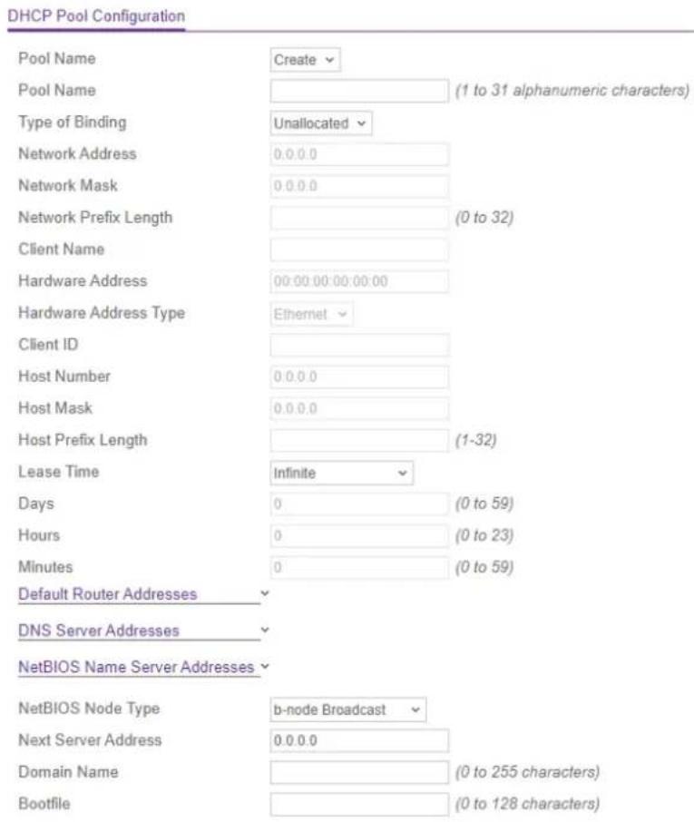
- From the Pool Name menu, select Create.
The Pool Name eld displays.
- In the Pool Name eld, type a name for the new pool.
The name can be up to 31 characters in length.
-
Select the type of binding for the pool:
-
Unallocated: No further configurations are required. Continue with the next step.
• Dynamic: Congure the following settings:
• Network Address. The subnet IP address for the dynamic DHCP pool.
• Network Mask: The network mask for the dynamic DHCP pool.
• Network Prex Length: The subnet number for the dynamic DHCP pool. The range is from 0 to 32.
Note: For a dynamic DHCP pool, you can congregate either the network mask or the prex length.
- Manual: Congure the following settings:
- Client Name: The DHCP client name.
- Hardware Address: The hardware MAC address of the DHCP client.
- Hardware Address Type: The protocol of the MAC address of the DHCP client. The type can be Ethernet or IEEE802. The default is Ethernet.
- Client ID: The client ID of the DHCP client.
- Host Number: The IP address for the manual binding of the DHCP client.
- Host Mask: The subnet mask for the manual binding of the DHCP client.
- Host Prex Length: The subnet mask for the manual binding of the DHCP client. The range is from 0 to 32.
Note: For a manually added DHCP client, you can congregate either the network mask or the prex length.
-
From the Lease Time menu, select how the binding is leased:
-
Innite: For a dynamic binding, innate is a lease period of 60 days. For manually added binding, the lease period is indenite. No further congrurations are required. Continue with the next step.
- Specied Duration: Congure the following settings:
- Days: The number of days of the lease period. The range is from 0 to 59. The default is 1.
• Hours: The number of hours of the lease period. The range is from 0 to 22.
- Minutes: The number of minutes of the lease period. The range is from 0 to 86399.
- To congregate default router addresses, click the Default Router Addresses link, and add up to eight IP address for default routers, in order of preference.
- To congregate DNS server addresses, click the DNS Server Addresses link, and add up to eight IP address for DNS server, in order of preference.
-
To congregate NetBIOS name server addresses, click the NetBIOS name server addresses link, and add up to eight IP address for NetBIOS name servers, in order of preference.
-
From the NetBIOS Node Type menu, select one of the following NetBIOS node types for DHCP clients:
-
b-node Broadcast
• p-node Peer-to-Peer - m-node Mixed
-
h-node Hybrid
-
In the Next Server Address eld, enter the IP address of the next server in the boc process for a DHCP client.
- In the Domain Name eld, enter the domain name in the boot process for a DHCP client.
The domain name can be up to 255 characters in length.
- In the Bootle eld, enter the name of the default boot image in the boot process for a DHCP client.
The domain name can be up to 128 characters in length.
- Click the Add button.
The pool conguration is added.
- To save the settings to the running conguration, click the Save icon.
Change a DHCP pool You can change an existing DHCP pool. To change a DHCP pool:
- Launch a web browser.
-
In the address eld of your web browser, enter the IP address of the switch. The login page displays.
-
Click the Main UI Login button.
The main UI login page displays in a new tab.
- Enter admin as the user name, enter your local device password, and click the Login button.
The rst time that you log in, no password is required. However, you then must specify a local device password to use each subsequent time that you log in.
The System Information page displays.
- Select System > Services > DHCP Server > DHCP Pool Conguration.
The DHCP Pool Conguration page displays.
-
From the Pool Name menu, select the pool.
-
Change the settings as needed.
For more information about the settings, see Create a DHCP pool on page 102.
- Click the Apply button.
Your settings are saved.
- To save the settings to the running conguration, click the Save icon.
Remove a DHCP pool You can remove a DHCP pool that you no longer need. To remove a DHCP pool:
-
Launch a web browser.
-
In the address eld of your web browser, enter the IP address of the switch.
The login page displays.
- Click the Main UI Login button.
The main UI login page displays in a new tab.
- Enter admin as the user name, enter your local device password, and click the Login button.
The rst time that you log in, no password is required. However, you then must specify a local device password to use each subsequent time that you log in.
The System Information page displays.
- Select System > Services > DHCP Server > DHCP Pool Conguration.
The DHCP Pool Conguration page displays.
-
From the Pool Name menu, select the pool.
-
Click the Delete button.
The pool is removed.
- To save the settings to the running conguration, click the Save icon.
Congure DHCP pool options
You can specify information that is included in the "options" eld of a DHCP message that the switch sends.
To congregate DHCP pool options:
-
Launch a web browser.
-
In the address eld of your web browser, enter the IP address of the switch.
The login page displays.
- Click the Main UI Login button.
The main UI login page displays in a new tab.
- Enter admin as the user name, enter your local device password, and click the Login button.
The rst time that you log in, no password is required. However, you then must specify a local device password to use each subsequent time that you log in.
The System Information page displays.
- Select System > Services > DHCP Server> DHCP Pool Options.
The DHCP Pool Options page displays.
-
From the Pool Name menu, select the pool name.
-
In the Option Code eld, specify the option code congured for the pool.
The range is from 1 to 254. For information about options and their format, see information about RFC 2132 at https://tools.ietf.org/html/rfc2132.
- Form the Option Type menu, select one of the following option types for the pool:
- ASCII: Enter the information in the Option Value eld in ASCII format.
- Hex: Enter the information in the Option Value eld in hexadecimal format. The possible formats are xx:xx and xxxx.xxxx.
- IP Address: In the Option Value eld, enter an IPv4 address.
-
In the Option Value eld, specify the option value for the pool according to your selection in the previous step.
-
Click the Add button.
The option code is added for the pool.
- To save the settings to the running conguration, click the Save icon.
Display DHCP server statistics
To display the DHCP server statistics:
-
Launch a web browser.
-
In the address eld of your web browser, enter the IP address of the switch.
The login page displays.
- Click the Main UI Login button.
The main UI login page displays in a new tab.
- Enter admin as the user name, enter your local device password, and click the Login button.
The rst time that you log in, no password is required. However, you then must specify a local device password to use each subsequent time that you log in.
The System Information page displays.
- Select System > Services > DHCP Server > DHCP Server Statistics.
The DHCP Server Statistics page displays.
- To refresh the page, click the Refresh button.
The following table describes the noncongorable elds on the page.
Table 30. DHCP server statistics information
| DescriptionField | |
| Binding Details | |
| The number of automatic bindings on the DHCP server.Automatic Bindings | |
| The number of expired bindings on the DHCP server.Expired Bindings | |
| The number of the malformed messages on the DHCP server.Malformed Message | |
| Message Received | |
| The number of DHCPDISCOVER messages received by the DHCP server.DHCPDISC | |
| The number of DHCPREQUEST messages received by the DHCP server.DHCPREQUEST | |
| The number of DHCPDECLINE messages received by the DHCP server.DHCPDECL | |
| The number of DHCPRELEASE messages received by the DHCP server.DHCPRELEASE | |
| The number of DHCPINFORM messages received by the DHCP server.DHCPINFOR | |
| Message Sent | |
| The number of DHCPOFFER messages sent by the DHCP server.DHCPOFFER | |
Table 30. DHCP server statistics information (Continued)
| DescriptionField |
| The number of DHCPACK messages sent by the DHCP server.DHCPACK |
| The number of DHCPNAK messages sent by the DHCP server.DHCPNAK |
Display the DHCP bindings
To display the DHCP bindings:
- Launch a web browser.
-
In the address eld of your web browser, enter the IP address of the switch. The login page displays.
-
Click the Main UI Login button. The main UI login page displays in a new tab.
-
Enter admin as the user name, enter your local device password, and click the Login button. The rst time that you log in, no password is required. However, you then must specify a local device password to use each subsequent time that you log in. The System Information page displays.
-
Select System > Services > DHCP Server > DHCP Bindings Information. The DHCP Bindings Information page displays. The table displays information about all bindings.
-
To search for a binding by IP address, enter the IP address in the Search Binding IP eld and click the Go button. Information about the binding displays. The following table describes the noncongorable elds on the page.
Table 31. DHCP bindings information
| DescriptionField |
| The client's IP address.IP Address |
| The client's hardware address.Hardware Address |
Table 31. DHCP bindings information (Continued)
| DescriptionField |
| The remaining lease time in days, hours and minutes (dd:hh:mm format).Lease Time |
| The type of binding (Dynamic or Manual).Type |
Delete one or all dynamic DHCP bindings
To delete one or all dynamic DHCP bindings:
- Launch a web browser.
- In the address eld of your web browser, enter the IP address of the switch. The login page displays.
- Click the Main UI Login button. The main UI login page displays in a new tab.
-
Enter admin as the user name, enter your local device password, and click the Login button. The rst time that you log in, no password is required. However, you then must specify a local device password to use each subsequent time that you log in. The System Information page displays.
-
Select System > Services > DHCP Server > DHCP Bindings Information. The DHCP Bindings Information page displays.
-
Select one of the following radio buttons:
-
All Dynamic Bindings: All dynamic bindings must be cleared.
-
Specific Dynamic Binding: In the eld, specify the IP address of the dynamic binding that must be cleared.
-
Click the Clear button.
The selected binding or bindings are deleted. -
To save the settings to the running conguration, click the Save icon.
View bindings with DHCP conicts
You can view information about devices with IP address conicts. A conict might occur when the same IP address is assigned to two or more devices in the network.
To view DHCP bindings with conicts:
- Launch a web browser.
-
In the address eld of your web browser, enter the IP address of the switch. The login page displays.
-
Click the Main UI Login button. The main UI login page displays in a new tab.
-
Enter admin as the user name, enter your local device password, and click the Login button. The rst time that you log in, no password is required. However, you then must specify a local device password to use each subsequent time that you log in. The System Information page displays.
-
Select System > Services > DHCP Server > DHCP Conicts Information. The DHCP Conicts Information page displays. The table displays information about all bindings with conicts.
-
To search for a binding with an IP address conict, enter the IP address in the Sear Conict IP Address eld and click the Go button. Information about the binding displays.
The following table describes the noncongorable elds on the page.
Table 32. DHCP conicts information
| DescriptionField |
| The IP address of the DHCP client.IP Address |
| The hardware address if the DHCP client.Hardware Address |
Table 32. DHCP conicts information (Continued)
| DescriptionField | |
| Detection Method | The method with which the IP address of the DHCP client was detected on the DHCP server. |
| Detection Time | The time when the conict was detected in the days;hours;minutes;seconds format since the switch was last restarted. |
Delete one or all DHCP bindings with conicts
To delete one or all DHCP bindings with conicts:
- Launch a web browser.
- In the address eld of your web browser, enter the IP address of the switch. The login page displays.
- Click the Main UI Login button. The main UI login page displays in a new tab.
- Enter admin as the user name, enter your local device password, and click the Login button. The rst time that you log in, no password is required. However, you then must specify a local device password to use each subsequent time that you log in. The System Information page displays.
- Select System > Services > DHCP Server > DHCP Conicts Information. The DHCP Conicts Information page displays.
- Select one of the following radio buttons:
- All Address Conicts: All bindings with IP address conicts must be cleared.
- Specific Address Conict: In the eld, specify the IP address of the binding with a conict that must be cleared.
-
Click the Clear button. The selected binding or bindings are deleted.
-
To save the settings to the running conguration, click the Save icon.
DHCP relay and relay statistics
If the switch is functioning as a Layer 3 device, you can enable the Layer 3 DHCP rela agent and let the switch relay DHCP messages between DHCP clients and DHCP servers that are located in a different IP subnet.
To congregate a DHCP relay and display relay statistics:
- Launch a web browser.
-
In the address eld of your web browser, enter the IP address of the switch. The login page displays.
-
Click the Main UI Login button. The main UI login page displays in a new tab.
-
Enter admin as the user name, enter your local device password, and click the Login button. The rst time that you log in, no password is required. However, you then must specify a local device password to use each subsequent time that you log in. The System Information page displays.
-
Select System > Services > DHCP Relay. The DHCP Relay page display.
-
in the Maximum Hop Count eld, enter the maximum number of hops a client request can take before being discarded. The range is from 1 to 16. The default is 4.
-
Select the Admin mode Disable or Enable radio button to disable or enable the DHCP relay on the switch.
-
In the Minimum Wait Time eld, enter the minimum time in seconds that the DHCP relay must wait before forwarding requests. The time is compared to the time stamp in the client's DHCP request packets, which represents the time since the client was powered up. Packets are forwarded only when the time stamp exceeds the minimum wait time. The range is from 0 to 100.
-
Select one of the following Circuit ID Option Mode radio buttons:
-
Enable: Relay agent options are added to requests before they are forwarded to the server and removed from replies before they are forwarded to clients.
-
Disable: R relay agent options are not added to requests before they are forwarded to the server and not removed from replies before they are forwarded to clients.
-
Click the Apply button.
Your settings are saved.
- To save the settings to the running conguration, click the Save icon.
- To refresh the information on the page, click the Refresh button.
The following table describes the noncongorable elds on the page.
Table 33. DHCP relay status information
| DescriptionField | |
| Requests Received | The total number of DHCP requests received from all clients since the time the switch was started. |
| Requests Relayed | The total number of DHCP requests forwarded to the server since the time the switch was started. |
| Packets Discarded | The total number of DHCP packets discarded by the relay agent since the time the switch was started. |
DHCP Layer 2 relay
If you enable and congregate a DHCP relay agent on the switch, some Layer 2 (L2) device do not need to connect to a DHCP server on the physical network. A relay agent automatically populates the gateway IP address (giaddr) eld and adds the Relay Agent Information option to DHCP messages. A DHCP server uses this option for IP addresses and other assignment policies. A DHCP relay agent is usually an IP routing-aware device, which is also referred to as a Layer 3 relay agent. In some network congrurations, L2 devices must append the Relay Agent Information option because they are closer to the end hosts.
An L2 device can operate as a bridge only for a network and might not include an IF address on the network. If an L2 device lacks an IPv4 source address, the device can relay packets directly to a DHCP server that is located on another network. In that situation, the L2 device can append the Relay Agent Information option and broadcast the DHCP message.
Congure the global DHCP L2 relay settings
To congregate the global DHCP L2 relay settings:
- Launch a web browser.
-
In the address eld of your web browser, enter the IP address of the switch. The login page displays.
-
Click the Main UI Login button. The main UI login page displays in a new tab.
-
Enter admin as the user name, enter your local device password, and click the Login button. The rst time that you log in, no password is required. However, you then must specify a local device password to use each subsequent time that you log in. The System Information page displays.
-
Select System > Services > DHCP L2 Relay > DHCP L2 Relay Global Configuration The DHCP L2 Relay Global Conguration page displays.
-
Select the Admin mode Disable or Enable radio button to disable or enable the DHCP L2 relay on the switch. The default is Disable.
-
In the DHCP L2 Relay VLAN Conguration section, congure the following settings:
-
VLAN ID: The ID of the VLAN that is already congured on the switch.
You cannot use this page to add a VLAN. For information about adding VLANs, see VLANs on page 191. - Admin mode: Enable or disable the DHCP L2 relay on the VLAN.
- Circuit ID mode: Enable or disable the circuit ID suboption of DHCP Option-82.
-
Remote ID String: Specify the remote ID if the Remote ID option is enabled.
-
Click the Apply button. Your settings are saved.
-
To save the settings to the running conguration, click the Save icon.
Congure a DHCP L2 relay interface
You can enable a DHCP L2 relay on an interface.
To congure DHCP L2 relay interface:
- Launch a web browser.
- In the address eld of your web browser, enter the IP address of the switch.
The login page displays.
- Click the Main UI Login button.
The main UI login page displays in a new tab.
- Enter admin as the user name, enter your local device password, and click the Login button.
The rst time that you log in, no password is required. However, you then must specify a local device password to use each subsequent time that you log in.
The System Information page displays.
- Select System > Services > DHCP L2 Relay > DHCP L2 Relay Interface Conguration.
The DHCP L2 Relay Interface Conguration displays.
- Select whether to display physical interfaces, LAGs, or both by clicking one of the following links above the table heading:
• 1: Only physical interfaces are displayed. This is the default setting.
- LAG: Only LAGs are displayed.
- All: Both physical interfaces and LAGs are displayed.
-
Select one or more interfaces by taking one of the following actions:
-
To congregate a single interface, select the check box associated with the interface, or type the interface number in the Go To Interface eld and click the Go button.
- To congregate multiple interfaces with the same settings, select the check box associated with each interface.
-
To congregate all interfaces with the same settings, select the check box in the heading row.
-
From the Admin mode menu, select to enable or disable the DHCP L2 relay on the interface.
The default is Disable.
- From the 82 Option Trust Mode menu, select to enable or disable the interface as a trusted interface for Relay Agent Information option (Option 82).
- Click the Apply button.
Your settings are saved.
- To save the settings to the running conguration, click the Save icon.
Display DHCP L2 relay interface statistics
To display the DHCP L2 relay interface statistics:
- Launch a web browser.
-
In the address eld of your web browser, enter the IP address of the switch. The login page displays.
-
Click the Main UI Login button. The main UI login page displays in a new tab.
-
Enter admin as the user name, enter your local device password, and click the Login button. The rst time that you log in, no password is required. However, you then must specify a local device password to use each subsequent time that you log in. The System Information page displays.
-
Select System > Services > DHCP L2 Relay > DHCP L2 Relay Interface Statistics. The DHCP L2 Relay Interface Statistics page displays.
-
Select whether to display physical interfaces, LAGs, or both by clicking one of the following links above the table heading:
• 1: Only physical interfaces are displayed. This is the default setting.
• VLANS: Only VLANs are displayed.
- LAG: Only LAGs are displayed.
- All: Both physical interfaces and LAGs are displayed.
- To refresh the information on the page, click the Refresh button. The following table describes the noncongorable elds on the page.
Table 34. DHCP L2 relay interface statistics information
| DescriptionField | |
| The interface from which the DHCP message is received.Interface | |
| UntrustedServerMsgsWithOpt82 | The number of DHCP messages with Option 82 received from an untrusted server.DescriptionField |
| UntrustedClientMsgsWithOpt82 | The number of DHCP messages with Option 82 received from an untrusted client. |
| TrustedServerMsgsWithoutOpt82 | The number of DHCP messages without Option 82 received from a trusted server. |
| TrustedClientMsgsWithoutOpt82 | The number of DHCP messages without Option 82 received from a trusted client. |
UDP relay
You can enable the switch to function as a UDP relay, which enables the switch to forw User Datagram Protocol (UDP) broadcast packets from a router to an IP address on a local or non-local subnet.
Congure the global UDP relay settings and add a U switch conguration
To congregate the global UDP relay settings and add a UDP switch conguration:
- Launch a web browser.
- In the address eld of your web browser, enter the IP address of the switch.
The login page displays. - Click the Main UI Login button.
The main UI login page displays in a new tab. - Enter admin as the user name, enter your local device password, and click the Login button.
The rst time that you log in, no password is required. However, you then must specify a local device password to use each subsequent time that you log in.
The System Information page displays. -
Select System > Services > UDP Relay > UDP Relay Global Conguration.
The UDP Relay Global Conguration page displays. -
Select the Admin mode Disable or Enable radio button to disable or enable the UDP relay on the switch.
The default is Disable.
-
In the UDP Relay Global Conguration section, congure the following settings:
-
Server Address: Enter the IPv4 address of the UDP relay server.
- UDP Port: Select one of the following types of UDP destination ports:
- Other: The UDP Port Other Value eld becomes available so that you can enter a custom UDP port number.
- dhcp: Relay DHCP (UDP port 67) packets.
- domain: Relay DNS (UDP port 53) packets.
- isakmp: Relay ISAKMP (UDP port 500) packets.
- mobile-ip: Relay Mobile IP (UDP port 434) packets
- nameserver: Relay IEN-116 Name Service (UDP port 42) packets
- netbios-dgm: Relay NetBIOS Datagram Server (UDP port 138) packets
- netbios-ns: Relay NetBIOS Name Server (UDP port 137) packets
- ntp: Relay network time protocol (UDP port 123) packets.
- pim-auto-rp: Relay PIM auto RP (UDP port 496) packets.
- rip: Relay Routing Image Protocol (RIP) (UDP port 520) packets
• tacacs: Relay TACACS (UDP port 49) packet
- tftp: Relay TFTP (UDP port 69) packets
• time: Relay time service (UDP port 37) packets
- UDP Port Other Value: If you select Other from the UDP Port menu, enter a custom UDP port number in the range from 0 to 65535.
- Click the Add button.
The UDP switch conguration is added.
The Hit Count eld displays the number of UDP packets that are detected on the UDP interface.
- To save the settings to the running conguration, click the Save icon.
Change a UDP switch conguration
To change a UDP switch conguration:
- Launch a web browser.
- In the address eld of your web browser, enter the IP address of the switch. The login page displays.
- Click the Main UI Login button. The main UI login page displays in a new tab.
- Enter admin as the user name, enter your local device password, and click the Login button. The rst time that you log in, no password is required. However, you then must specify a local device password to use each subsequent time that you log in. The System Information page displays.
- Select System > Services > UDP Relay > UDP Relay Global Conguration. The UDP Relay Global Conguration page displays.
- In the UDP Relay Global Conguration section, select the check box for the UDP switch conguration.
- Change the settings as needed. For more information about the settings, see Configure the global UDP relay settings and add a UDP switch conguration on page 118.
- Click the Apply button. Your settings are saved.
- To save the settings to the running conguration, click the Save icon.
Remove a UDP switch conguration
To remove a UDP switch conguration:
- Launch a web browser.
- In the address eld of your web browser, enter the IP address of the switch. The login page displays.
-
Click the Main UI Login button. The main UI login page displays in a new tab.
-
Enter admin as the user name, enter your local device password, and click the Login button.
The rst time that you log in, no password is required. However, you then must specify a local device password to use each subsequent time that you log in.
The System Information page displays.
- Select System > Services > UDP Relay > UDP Relay Global Conguration.
The UDP Relay Global Conguration page displays.
-
In the UDP Relay Global Conguration section, select the check box for the UDP switch conguration.
-
Click the Delete button.
The UDP switch conguration is removed.
- To save the settings to the running conguration, click the Save icon.
Add a UDP interface conguration
To add a UDP relay interface conguration:
- Launch a web browser.
- In the address eld of your web browser, enter the IP address of the switch. The login page displays.
- Click the Main UI Login button.
The main UI login page displays in a new tab.
- Enter admin as the user name, enter your local device password, and click the Login button.
The rst time that you log in, no password is required. However, you then must specify a local device password to use each subsequent time that you log in.
The System Information page displays.
- Select System > Services > UDP Relay > UDP Relay Interface Conguration.
The page UDP Relay Interface Conguration page displays.
- From the Interface menu, select the interface or VLAN for which you are adding the UDP conguration.
- in the Server Address eld, enter the IPv4 address of the UDP relay server.
-
From the UDP Port menu, select one of the following types of UDP destination port:
-
Other: The UDP Port Other Value eld becomes available so that you can enter a custom UDP port number.
- dhcp: Relay DHCP (UDP port 67) packets.
- domain: Relay DNS (UDP port 53) packets.
- isakmp: Relay ISAKMP (UDP port 500) packets.
- mobile-ip: Relay Mobile IP (UDP port 434) packets
- nameserver: Relay IEN-116 Name Service (UDP port 42) packets
- netbios-dgm: Relay NetBIOS Datagram Server (UDP port 138) packets
- netbios-ns: Relay NetBIOS Name Server (UDP port 137) packets
- ntp: Relay network time protocol (UDP port 123) packets.
- pim-auto-rp: Relay PIM auto RP (UDP port 496) packets.
- rip: Relay Routing Image Protocol (RIP) (UDP port 520) packets
• tacacs: Relay TACACS (UDP port 49) packet -
tftp: Relay TFTP (UDP port 69) packets
• time: Relay time service (UDP port 37) packets -
If you select Other from the UDP Port menu, enter a custom UDP port number in the UDP Port Other Value. eld.
The port number can be in the range from 0 to 65535.
-
From the Discard menu, select if packets that match the condition are dropped:
-
Enable: The packets are dropped. This selection functions only is you enter 0.0.0.0 as the server IP address.
-
Discard: The packets are not dropped. This selection functions if the server IP address is not 0.0.0.0.
-
Click the Add button.
The UDP interface conguration is added.
The Hit Count eld displays the number of UDP packets that are detected on the UDP interface.
- To save the settings to the running conguration, click the Save icon.
Change a UDP interface conguration
To change a UDP switch conguration:
- Launch a web browser.
-
In the address eld of your web browser, enter the IP address of the switch. The login page displays.
-
Click the Main UI Login button.
The main UI login page displays in a new tab.
- Enter admin as the user name, enter your local device password, and click the Login button.
The rst time that you log in, no password is required. However, you then must specify a local device password to use each subsequent time that you log in.
The System Information page displays.
- Select System > Services > UDP Relay > UDP Relay Interface Conguration.
The page UDP Relay Interface Conguration page displays.
-
From the Interface menu, select the interface or VLAN.
-
Change the settings as needed.
For more information about the settings, see Add a UDP interface conguration on page 121.
- Click the Apply button.
Your settings are saved.
- To save the settings to the running conguration, click the Save icon.
Remove a UDP switch conguration
To remove a UDP switch conguration:
-
Launch a web browser.
-
In the address eld of your web browser, enter the IP address of the switch. The login page displays.
-
Click the Main UI Login button.
The main UI login page displays in a new tab.
- Enter admin as the user name, enter your local device password, and click the Login button.
The rst time that you log in, no password is required. However, you then must specify a local device password to use each subsequent time that you log in.
The System Information page displays.
- Select System > Services > UDP Relay > UDP Relay Interface Conguration.
The page UDP Relay Interface Conguration page displays.
-
From the Interface menu, select the interface or VLAN.
-
Click the Delete button.
The UDP switch conguration is removed.
- To save the settings to the running conguration, click the Save icon.
DHCPv6 server
You can congregate settings for a DHCPv6 server, DHCPv6 pools, DHCPv6 prex delegation, DHCPv6 interfaces. and DHCPv6 bindings. You can also view DHCPv6 statistics.
Enable the DHCPv6 server
By default, the DHCPv6 server is disabled. You can enable it so that the switch can ass network conguration information to IPv6 clients.
To enable the DHCPv6 server on the switch:
- Launch a web browser.
- In the address eld of your web browser, enter the IP address of the switch. The login page displays.
- Click the Main UI Login button.
The main UI login page displays in a new tab.
- Enter admin as the user name, enter your local device password, and click the Login button.
The rst time that you log in, no password is required. However, you then must specify a local device password to use each subsequent time that you log in.
The System Information page displays.
- Select System > Services > DHCPv6 Server > DHCPv6 Server Conguration.
The DHCPv6 Server Conguration page displays.
- Select the Admin mode Enable radio button.
The default value is Disable.
- Click the Apply button.
Your settings are saved.
The DHCPv6 Server DUID eld displays the DHCP Unique Identier (DUID) of the DHCPv6 server.
- To save the settings to the running conguration, click the Save icon.
Manage DHCPv6 pools
A DHCPv6 pool provides network conguration information that is available to DHCPv6 clients that request such information. You can add, change, and remove DHCPv6 pools.
Create a DHCPv6 pool A DHCPv6 pool provides network configuration information that is available to DHCPv6 clients that request such information.
To create a DHCPv6 pool:
- Launch a web browser.
- In the address eld of your web browser, enter the IP address of the switch.
The login page displays.
- Click the Main UI Login button.
The main UI login page displays in a new tab.
- Enter admin as the user name, enter your local device password, and click the Login button.
The rst time that you log in, no password is required. However, you then must specify a local device password to use each subsequent time that you log in.
The System Information page displays.
- Select System > Services > DHCPv6 Server > DHCPv6 Pool Conguration.
The DHCPv6 Pool Conguration page displays.
- From the Pool Name menu, select Create.
- In the Pool Name eld, type a name that identities the DHCPv6 server pool.
The name can be up to 31 characters in length.
- Click the Default Router Addresses link and specify the list of default IPv6 router addresses for the pool.
You can specify up to eight default router addresses in order of preference.
- Click the Domain Name link and specify the list of IPv6 domain names for the poo
A domain name can be up to 255 alphanumeric characters in length.
- Click the Apply button.
Your settings are saved.
- To save the settings to the running conguration, click the Save icon.
Change a DHCPv6 pool You can change an existing DHCPv6 pool. To change a DHCPv6 pool:
- Launch a web browser.
- In the address eld of your web browser, enter the IP address of the switch. The login page displays.
- Click the Main UI Login button. The main UI login page displays in a new tab.
-
Enter admin as the user name, enter your local device password, and click the Login button. The rst time that you log in, no password is required. However, you then must specify a local device password to use each subsequent time that you log in. The System Information page displays.
-
Select System > Services > DHCPv6 Server > DHCPv6 Pool Conguration. The DHCPv6 Pool Conguration page displays.
-
From the Pool Name menu, select the name for the pool. You cannot change the pool name.
-
Click the Default Router Addresses link and change the list of default IPv6 router addresses for the pool. You can specify up to eight default router addresses in order of preference.
-
Click the Domain Name link and change the list of IPv6 domain names for the pod A domain name can be up to 255 alphanumeric characters in length.
-
Click the Apply button. Your settings are saved.
-
To save the settings to the running conguration, click the Save icon.
Delete a DHCPv6 pool You can delete a DHCPv6 pool that you no longer need. To delete a DHCPv6 pool:
- Launch a web browser.
- In the address eld of your web browser, enter the IP address of the switch. The login page displays.
-
Click the Main UI Login button. The main UI login page displays in a new tab.
-
Enter admin as the user name, enter your local device password, and click the Login button.
The rst time that you log in, no password is required. However, you then must specify a local device password to use each subsequent time that you log in.
The System Information page displays.
- Select System > Services > DHCPv6 Server > DHCPv6 Pool Conguration.
The DHCPv6 Pool Conguration page displays.
-
From the Pool Name menu, select the name for the pool.
-
Click the Delete button.
The pool is deleted.
- To save the settings to the running conguration, click the Save icon.
Manage DHCPv6 prex delegation for pools
A prex delegation conguration supplies an IPv6 prex and prex length to a DHCPv6 pool that provide network conguration information to DHCPv6 clients that request such information.
A DHCPv6 client can request multiple IPv6 prexes and can also request specific IPv6 prexes. If a DHCPv6 pool contains the specific prex that a DHCPv6 client requests, the prex is delegated to the client. Otherwise, the rst available IPv6 prex in a pool is delegated to the client.
Create a DHCPv6 prex delegation conguration for a pool To create a DHCPv6 prex delegation conguration for a pool:
-
Launch a web browser.
-
In the address eld of your web browser, enter the IP address of the switch. The login page displays.
-
Click the Main UI Login button.
The main UI login page displays in a new tab.
- Enter admin as the user name, enter your local device password, and click the Login button.
The rst time that you log in, no password is required. However, you then must specify a local device password to use each subsequent time that you log in.
The System Information page displays.
- Select System > Services > DHCPv6 Server > DHCPv6 Prex Delegation Conguration.
The DHCPv6 Prex Delegation Conguration page displays.
-
From the Pool Names menu, select a pool.
-
In the Prex eld, specify the IPv6 prex.
-
In the Prex Length eld, specify the length that is associated with the IPv6 prex.
-
In the DUID eld, specify the DHCP Unique Identier (DUID) that is associated with the IPv6 prex.
Note: The DUID and client name are used only if a device requests a prex. In this way, the device receives an IPv6 prex instead of specific IPv6 address. If you assign a specific IPv6 address to the device, you can leave the DUID and Client Name elds blank.
-
In the Client Name, eld, enter a client name that is associated with the IPv6 prex. The name, which is useful for logging or tracing, can be up to 31 characters.
-
In the Valid Lifetime eld, enter the time in seconds after which the IPv6 prex times out. Enter a value between 0 and 4294967295.
-
In the Prefer Lifetime eld, enter the preferred time in seconds after which the IPv6 prex times out. Enter a value between 0 and 4294967295.
-
Click the Add button. The prex delegation conguration is added for the selected pool.
-
To save the settings to the running conguration, click the Save icon.
Change a DHCPv6 prex delegation conguration for a pool You can change an existing DHCPv6 prex delegation conguration.
To create a DHCPv6 prex delegation conguration for a pool:
- Launch a web browser.
-
In the address eld of your web browser, enter the IP address of the switch. The login page displays.
-
Click the Main UI Login button. The main UI login page displays in a new tab.
-
Enter admin as the user name, enter your local device password, and click the Login button.
The rst time that you log in, no password is required. However, you then must specify a local device password to use each subsequent time that you log in.
The System Information page displays.
- Select System > Services > DHCPv6 Server > DHCPv6 Prex Delegation Conguration.
The DHCPv6 Prex Delegation Conguration page displays.
-
From the Pool Names menu, select the pool.
-
Change the settings as needed.
For more information about the settings, see Create a DHCPv6 prex delegation conguration for a pool on page 127.
- Click the Apply button.
Your settings are saved.
- To save the settings to the running conguration, click the Save icon.
Delete a DHCPv6 prex delegation conguration for a pool You can delete an existing DHCPv6 prex delegation conguration that you no longer need. To delete a DHCPv6 prex delegation conguration for a pool:
-
Launch a web browser.
-
In the address eld of your web browser, enter the IP address of the switch. The login page displays.
-
Click the Main UI Login button.
The main UI login page displays in a new tab.
- Enter admin as the user name, enter your local device password, and click the Login button.
The rst time that you log in, no password is required. However, you then must specify a local device password to use each subsequent time that you log in.
The System Information page displays.
- Select System > Services > DHCPv6 Server > DHCPv6 Prex Delegation Conguration.
The DHCPv6 Prex Delegation Conguration page displays.
-
From the Pool Names menu, select the pool.
-
Click the Delete button.
The prex delegation conguration is deleted.
- To save the settings to the running conguration, click the Save icon.
Congure the DHCPv6 settings for an interface
You can congregate the DHCPv6 settings for an interface so that the interface can provide DHCPv6 services to attached devices.
To congregate the DHCPv6 settings for an interface:
- Launch a web browser.
-
In the address eld of your web browser, enter the IP address of the switch. The login page displays.
-
Click the Main UI Login button. The main UI login page displays in a new tab.
-
Enter admin as the user name, enter your local device password, and click the Login button. The rst time that you log in, no password is required. However, you then must specify a local device password to use each subsequent time that you log in. The System Information page displays.
-
Select System > Services > DHCPv6 Server > DHCPv6 Interface Conguration. The DHCPv6 Interface Conguration page displays.
-
Select one or more interfaces by taking one of the following actions:
-
To congregate a single interface, select the check box associated with the interface, or type the interface number in the Go To Interface eld and click the Go button.
- To congregate multiple interfaces with the same settings, select the check box associated with each interface.
-
To congregate all interfaces with the same settings, select the check box in the heading row.
-
From the Admin mode menu, select to enable or disable the DHCPv6 server mode on the interface.
Note: DHCPv6 server and DHCPv6 relay functions are mutually exclusive. For information about conguring an interface as a DHCPv6 relay, see DHCPv6 relay interface on page 136.
- From the Pool Name eld, select a DHCPv6 pool.
AV Line of Fully Managed Switches M4250 Series Main User Manual
For more information, see Manage DHCPv6 pools on page 125.
- From the Rapid Commit menu, select to enable or disable an abbreviated exchange between the device that requests IPv6 information and the DHCPv6 server. This setting is optional.
- In the Preference eld, specify the preference value that a device can use to determine the preference of this interface in relation to other DHCPv6 servers. You can enter a value from 0 to 4294967295. The default is 0.
- Click the Apply button. Your settings are saved.
- To save the settings to the running conguration, click the Save icon.
Display the DHCPv6 bindings
After a client acquires IPv6 congruration information from a DHCPv6 server, the server adds an entry to the DHCPv6 bindings table.
To display DHCPv6 bindings information:
- Launch a web browser.
- In the address eld of your web browser, enter the IP address of the switch. The login page displays.
- Click the Main UI Login button. The main UI login page displays in a new tab.
- Enter admin as the user name, enter your local device password, and click the Login button. The rst time that you log in, no password is required. However, you then must specify a local device password to use each subsequent time that you log in. The System Information page displays.
- Select System > Services > DHCPv6 Server > DHCPv6 Bindings Information. The DHCPv6 Bindings Information page displays.
- To search for a binding, enter the IPv6 address in the Search Binding IP eld and click the Go button. Information about the binding displays.
- The following table describes the noncongorable elds on the page.
- To refresh the page, click the Refresh button.
The following table describes the noncongorable elds on the page.
Table 35. DHCPv6 binding Information
| DescriptionField | |
| The IPv6 address of the client associated with the binding.Client Address | |
| The interface number on which the client binding occurred.Client Interface | |
| Client DUID | The DHCPv6 Unique Identier (DUID) of the client. The DUID is a combination of the client's hardware address and client identier. |
| The IPv6 address for the delegated prex associated with this binding.Prex | |
| The IPv6 mask length for the delegated prefix associated with this binding.Prex Le | |
| The type of IPv6 prex associated with this binding.Prex Type | |
| The number of seconds until the prex associated with a binding expires.Expiry Ti | |
| Valid Lifetime | The maximum amount of time in seconds that the client is allowed to use the prex. |
| Prefer Lifetime | The preferred amount of time in seconds that the client is allowed to use the prex. |
Display DHCPv6 server statistics
You can display the DHCPv6 server statistics, including information about the DHCPv6 messages, sent, received, and discarded globally and on each interface.
To display DHCPv6 server statistics:
- Launch a web browser.
-
In the address eld of your web browser, enter the IP address of the switch. The login page displays.
-
Click the Main UI Login button. The main UI login page displays in a new tab.
-
Enter admin as the user name, enter your local device password, and click the Login button. The rst time that you log in, no password is required. However, you then must specify a local device password to use each subsequent time that you log in.
The System Information page displays.
5. Select System > Services > DHCPv6 Server > DHCPv6 Server Statistics.
The DHCPv6 Server Statistics page displays.
6. Do one of the following:
- Display statistics for one interface: From the Interface menu, select the interface.
- Display statistics for all interfaces: From the Interface menu, select All.
7. To refresh the page, click the Refresh button.
The following table describes the noncongorable elds on the page.
Table 36. DHCPv6 server statistics information
| DescriptionField | |
| Messages Received | |
| Total DHCPv6 Packets Received | The number of DHCPv6 messages received. The DHCPv6 messages sent from a DHCP v6 client to a DHCP v6 server include solicit, request, conrm, renew, rebind, release, decline, and information-request messages. Additionally, a DHCP v6 relay agent can forward relay-forward messages to a DHCP v6 server. |
| DHCPv6 Solicit Packets Received | The number of DHCPv6 Solicit messages received. This type of message is sent by a client to locate DHCPv6 servers. |
| The number of requests received.DHCPv6 Request Packets Received | |
| DHCPv6 Conrm Packets Received | The number of DHCPv6 Conrm messages received. This type of message is sent by a client to all DHCPv6 servers to determine whether its conguration is valid for the connected link. |
| DHCPv6 Renew Packets Received | The number of DHCPv6 Renew messages received. This type of message is sent by a client to extend and update the conguration information provided by the DHCPv6 server. |
| DHCPv6 Rebind Packets Received | The number of DHCPv6 Rebind messages received. This type of message is sent by a client to any DHCPv6 server when it does not receive a response to a Renew message. |
| DHCPv6 Release Packets Received | The number of DHCPv6 Release messages received. This type of message is sent by a client to indicate that it no longer needs the assigned address. |
| DHCPv6 Decline Packets Received | The number of DHCPv6 Decline messages received. This type of message is sent by a client to the DHCPv6 server to indicate that an assigned address is already in use on the link. |
| DHCPv6 Inform Packets Received | The number of DHCP v6 information-request messages received. This type of message is sent by a client to request configuration information other than IP address assignment. |
| DHCPv6 Relay-forward Packets Received | The number of DHCPv6 relay-forward messages received. This type of message is sent by a relay agent to forward messages to servers. |
| DHCPv6 Relay-reply Packets Received | The number of DHCP v6 relay-reply messages received. This type of message is sent by a server to a DHCP v6 relay agent and contains the message for the relay agent to deliver to the client. |
| DHCPv6 Malformed Packets Received | The number of DHCPv6 messages received but dropped because they were malformed. |
| The number of packets discarded. Received DHCPv6 Packets Discarded | |
| Messages Sent | |
| Total DHCPv6 Packets Sent | The number of DHCPv6 messages sent. The DHCPv6 messages sent from a DHCPv6 server to a DHCPv6 client include Advertise, Reply, Recongure, and Relay-Reply messages. |
| DHCPv6 Advertisement Packets Transmitted | The number of DHCPv6 Advertise messages sent. This type of message is sent by a server to a DHCPv6 client in response to a Solicit message and indicates that it is available for service. |
| DHCPv6 Reply Packets Transmitted | The number of DHCPv6 Reply messages sent to a DHCPv6 client in response to a solicit, request, renew, rebind, information-request, conrm, release, or decline message. |
| DHCPv6 Recong Packets Transmitted | The number of DHCPv6 recongure messages sent. This type of message is sent by a server to a DHCPv6 client to inform the client that the server has new or updated information. The client then typically initiates a renew/reply or Information-request/reply transaction with the server to receive the updated information.DescriptionField |
| DHCPv6 Relay-forward Packets Transmitted | The number of DHCPv6 Relay-Forward messages sent. This type of message is sent by a relay agent to forward messages to servers. |
| DHCPv6 Relay-reply Packets Transmitted | The number of DHCPv6 Relay-Reply messages sent. This type of message is sent by a server to a DHCPv6 relay agent and contains the message for the relay agent to deliver to the client. |
Delete DHCPv6 statistics for one or all interfaces
To delete DHCPv6 statistics for one or all interfaces:
- Launch a web browser.
- In the address eld of your web browser, enter the IP address of the switch. The login page displays.
- Click the Main UI Login button. The main UI login page displays in a new tab.
- Enter admin as the user name, enter your local device password, and click the Login button. The rst time that you log in, no password is required. However, you then must specify a local device password to use each subsequent time that you log in. The System Information page displays.
- Select System > Services > DHCPv6 Server > DHCPv6 Server Statistics. The DHCPv6 Server Statistics page displays.
-
Do one of the following:
-
Delete statistics for one interface: From the Interface menu, select the interface.
-
Delete statistics for all interfaces: From the Interface menu, select All.
-
Click the Clear button.
The selected statistics are deleted.
- To save the settings to the running conguration, click the Save icon.
DHCPv6 relay interface
A DHCPv6 relay agent allows sub-options to be attached to messages that are being relayed by the switch to a DHCPv6 server. In turn, the DHCPv6 server can use this information in determining an address to assign to a DHCPv6 client.
To congregate an interface as a DHCPv6 relay:
- Launch a web browser.
- In the address eld of your web browser, enter the IP address of the switch.
The login page displays.
- Click the Main UI Login button.
The main UI login page displays in a new tab.
- Enter admin as the user name, enter your local device password, and click the Login button.
The rst time that you log in, no password is required. However, you then must specify a local device password to use each subsequent time that you log in.
The System Information page displays.
- Select System > Services > DHCPv6 Relay.
The DHCPv6 Relay page displays.
The DHCPv6 Interface Conguration page displays.
-
Select one or more interfaces by taking one of the following actions:
-
To congregate a single interface, select the check box associated with the interface, or type the interface number in the Go To Interface eld and click the Go button.
- To congregate multiple interfaces with the same settings, select the check box associated with each interface.
-
To congregate all interfaces with the same settings, select the check box in the heading row.
-
From the Admin mode menu, select to enable or disable the DHCPv6 relay mode on the interface.
Note: DHCPv6 relay and DHCPv6 server functions are mutually exclusive. For information about conguring an interface as a DHCPv6 server, see Congure the DHCPv6 settings for an interface on page 130.
-
From the Relay Interface menu, select the interface, LAG, or VLAN that is connected to the DHCPv6 relay server.
-
In the Destination IP Address eld, specify the IPv6 address for the DHCPv6 relay server.
- In the Remote ID eld, specify the relay agent information option.
The remote ID is derived from the DHCPv6 server DUID and the relay interface number, or you can specify is as a user-dened string. - Click the Apply button.
Your settings are saved. - To save the settings to the running conguration, click the Save icon.
Power over Ethernet
You can congregate the global Power over Ethernet (PoE) congruration settings and the PoE settings for each port.
PoE concepts
The Power over Ethernet (PoE) models support eight PoE+ or PoE++ ports with the po capacities and budgets that are described in the following table.
Table 37. PoE port capacities and budgets
| Switch PoE BudgetPort CapacityPoE portsMode | |
| 125W30W8 PoE+ (802.3at)M4250-10G2F-PoE+ | |
| 240W30W8 PoE+ (802.3at)M4250-10G2XF-PoE+ | |
| 720W90W8 PoE++ (802.3bt)M4250-10G2XF-PoE- | |
| 300W30W8 PoE+ (802.3at)M4250-26G4F-PoE+ | |
| 480W30W8 PoE+ (802.3at)M4250-26G4XF-PoE+ | |
| 90W8 PoE++ (802.3bt)M4250-26G4F-PoEh+internal PSUs connected | |
| 480W30W8 PoE+ (802.3at)M4250-40G8F-PoE+ | |
| 960W30W8 PoE+ (802.3at)M4250-40G8XF-PoE+ | |
| 90W8 PoE++ (802.3bt)M4250-40G8XF-PoE+ +internal PSUs connected |
Supplied power is prioritized according to the port order, up to the total power budget of the device. Port 1 receives the highest PoE priority, while port 8 is relegated to the lowest PoE priority.
If the power requirements for attached powered devices (PDs) exceed the total power budget of the switch, the PoE power to the device on the highest-numbered active Pol port is disabled to make sure that the devices connected to the higher-priority, lower-numbered PoE ports are supported rst.
Although a device might be listed as an 802.3bt PoE++-powered or 802.3at PoE+-powered device, it might not require the maximum power limit that is specied by its IEEE standard. Many devices require less power, allowing all 8 PoE ports to be active simultaneously when the devices correctly report their PoE class to the switch.
The following table shows the standard power ranges, calculated with the maximum cable length of 328 feet (100 meters). If a device receives insufficient PoE power from the switch, consider using a shorter cable.
Table 38. PoE classes and PoE power allocations
| Device Class | Standard | Class Description Company | Makein RoE Power Reserved for the PD | Power Delivered to the PD |
0.44W-15.8W15.4WDefault power (full)Pc
| PoE, PoE+, and PoE+Mery low p0.44W-3.84W4.0W | ||||
| 2 | PoE, PoE+, and PoE++ | Low power | 7.0W | 3.84W-7.2W |
| PoE, P.42W-15.0WpE4W Mid power | ||||
| 4 | PoE+ and PoE++ | High power | 30.0W | 12.95W-30.8W |
| 5 | PoE-25.5W-47.0W45.0WUltra high power | |||
| 6 | PoE-51.0W-64.4W90.0WUltra high power | |||
| Device Class | Standard | Class Description Company | Make RoE Power Reserved for the PD | Power Delivered to the PD |
| 62.0W-81.1W75.0WUltra high powerPoE | ||||
| 71.0W-96.5W90.0WUltra high powerPoE | ||||
Congure the global PoE settings
To congregate the global PoE setting:
- Launch a web browser.
-
In the address eld of your web browser, enter the IP address of the switch. The login page displays.
-
Click the Main UI Login button. The main UI login page displays in a new tab.
-
Enter admin as the user name, enter your local device password, and click the Login button. The rst time that you log in, no password is required. However, you then must specify a local device password to use each subsequent time that you log in. The System Information page displays.
-
Select System > PoE > Basic > PoE Conguration. The PoE Conguration page displays.
-
In the System Usage Threshold eld, enter a number from 1 to 99 to set the threshold level at which a trap is sent if the consumed power exceeds the threshold power.
-
From the Power Management mode menu, select the power management algorithm that the switch uses to deliver power to the requesting PDs:
-
Static: Select Static to specify that the power allocated for each port depends on the type of power threshold that is congured on the port.
-
Dynamic: Select Dynamic to specify that the power consumption on each port is measured and calculated in real time. This is the default setting.
-
To set the traps, in the PoE Trap Conguration section, select one of the following radio buttons:
-
Enable: Activates the PoE traps. This is the default setting.
-
Disable: Deactivate the PoE traps.
-
Click the Apply button.
Your settings are saved.
- To save the settings to the running conguration, click the Save icon.
The following table describes the noncongorable elds on the page.
Table 39. PoE information
| DescriptionField | |
| The rmware version of the PoE software.Firmware Version | |
| The power status.Power Status | |
| The maximum power in watts the switch can deliver to all ports.Total Power Available (W) | |
| Threshold Power (W) | If the consumed power is below the threshold power, the switch can power up another port. The consumed power can be between the nominal and threshold power. The threshold power is displayed in watts.Note: The threshold power value is determined by the value that you enter in the System Usage Threshold eld. |
| Total power in watts that is being delivered to all ports.Consumed Power (W) |
Congure the PoE ports settings
To congregate the PoE ports settings:
- Launch a web browser.
- In the address eld of your web browser, enter the IP address of the switch. The login page displays.
- Click the Main UI Login button. The main UI login page displays in a new tab.
- Enter admin as the user name, enter your local device password, and click the Login button. The rst time that you log in, no password is required. However, you then must specify a local device password to use each subsequent time that you log in. The System Information page displays.
- Select System > PoE > Advanced > PoE Port Conguration. The PoE Port Conguration page displays.
-
Select one or more ports by taking one of the following actions:
-
To congregate a single port, select the check box associated with the port, or type the port number in the Go To Interface eld and click the Go button.
- To configure multiple ports with the same settings, select the check box associated with each port.
-
To congregate all ports with the same settings, select the check box in the heading row.
-
From the Port Power menu, select the administrative PoE mode of the port:
-
Enable: The port's capacity to deliver power is enabled. This is the default setting.
-
Disable: The port's capacity to deliver power is disabled.
-
From the Port Priority menu, select the priority for the port in relation to other po if the total power that the switch is capable of delivering exceeds the total power budget:
-
Low: Low priority. This is the default setting.
• Medium: Medium priority.
• High: High priority.
• Critical: Critical priority.
The port priority determines which ports can still deliver power after the total power delivered by the switch exceeds the total power budget. (In such a situation, the switch might not be able to deliver power to all connected devices.) If the same priority applies to two ports, the lower-numbered port receives higher priority.
- From the Power Mode menu, select the PoE mode that the port must function in:
- 802.3af: The port is powered in and limited to the IEEE 802.3af mode. A PD that requires IEEE 802.3at does not receive power if the port functions in IEEE 802.3af mode.
- Legacy: The port is powered using high-inrush current, which is used by legacy PDs that require more than 15W to power up.
- Pre-802.3at: The port is initially powered in the IEEE 802.3af mode and, before 75 msec pass, is switched to the high power IEEE 802.3at mode. Select this mod if the PD does not perform Layer 2 classification or if the switch performs 2-event Layer 1 classification.
- 802.3at: The port is powered in the IEEE 802.3at mode and is backward compatible with IEEE 802.3af. The 802.3at mode is the default mode. In this mode, if the switch detects that the attached PD requests more power than IEEE 802.3af, but is not an IEEE 802.3at Class 4 device, the PD does not receive power from a switch.
- Pre-802.3bt: The port supports Class 4 devices that use 4-pair PoE (4PPoE) to receive power higher than 30W but that are not compliant with IEEE 802.3bt. The port also supports the IEEE 802.3at and IEEE 802.3af modes.
- 802.3bt-Type3. The port supports the IEEE 802.3bt Type 3 mode, the IEEE 802.3at mode, and the IEEE 802.3af mode.
- 802.3bt: The port is powered in the IEEE 802.3bt mode and is backward compatible with IEEE 802.3at and IEEE 802.3af. In this mode, if the switch detects that the attached PD requests more power than IEEE 802.3at but is not an IEEE 802.3bt device, the PD does not receive power from the switch.
- From the Power Limit Type menu, select how the port controls the maximum power that it can deliver:
- None: For PoE+ (802.3at) ports, the port draws up to Class 0 maximum power in low power mode. In high power mode, the following applies:
- PoE+ (802.3at) ports: The port draws up to Class 4 maximum power.
- PoE++ (802.3bt) ports: The port draws up to Class 8 maximum power.
- Class: The port power limit is equal to the class of the attached PD. This is the default setting. The upper limit is the power that a port can deliver to a PD. The class is detected based on the PD that is attached to the port, and the following applies:
- PoE+ (802.3at) ports: Possible values are from Class 0 to Class 4.
- PoE++ (802.3bt) ports: Possible values are from Class 0 to Class 8.
- User: The port power limit is equal to the value that is specified in the Power Limit (W) eld.
Note: If a PD does not report its class correctly, use of these options can preserve additional PoE power by preventing the switch from delivering more power than the PD requires. However, depending on which option you select, a PD that does not report its class correctly might not power up at all.
- In the Power Limit (W) eld, enter the maximum power (in W) that the port can deliver.
The following applies:
- PoE+ (802.3at) ports: The range is from 3.0W to 30.0W.
- 802.3bt-Type3 ports (which is a selection from the Power Mode menu): The range is from 3.0W to 60.0W.
- PoE++ (802.3bt) ports: The range is from 3.0W to 99.9W.
- From the Detection Type menu, select how the port detects the attached PD:
- IEEE 802: The port performs a 4-point resistive detection. This is the default setting.
-
4pt 802.3af + Legacy: The port performs a 4-point resistive detection, and if required, continues with legacy detection.
• Legacy: The port performs legacy detection. -
From the Timer Schedule menu, select a timer schedule or select None, which is the default selection.
For information about setting up and conguring PoE timer schedules, see Timer schedules on page 145.
- Click the Apply button.
Your settings are saved.
- To save the settings to the running conguration, click the Save icon.
The following table describes the noncongorable elds on the page.
Table 40. PoE port information
| DescriptionField | |
| All ports supports high power mode.High Power | |
| The maximum power in Watts that can be provided by the port.Max Power (W) | |
| Class | The class denes the range of power that a powered device (PD) is drawing from the switch. The class denitions are as follows:0: 0.44W-15.8W1: 0.44W-3.84W2: 3.84W-7.2W3: 6.49W-15.9W4: 12.95W-30.8W5: 25.5W-47.0W6: 51.0W-64.4W7: 62.0W-81.1W8: 71.0W-96.5WUnknown: The class cannot be detected, or no PD is attached to the port. |
| The voltage that is delivered to the PD in volts.Output Voltage (Volts) | |
| The current that is delivered to the PD in mA.Output Current (mA) | |
| The power that is delivered to the PD in watts.Output Power (W) | |
| Status | The operational status of the port:Disabled: No power is delivered.Delivering Power. Power is being drawn by the PD.Requesting Power: The port is requesting power.Fault: A problem occurred with the power.Test: The port is in test mode.Other Fault: The port is idle because of an error condition.Searching: The port is not in one of the other states in this list. |
| Fault Status | The error description when the PoE port is in a fault state:No Error: The port is not in any error state and can provide power.MPS Absent: The port detected the absence of the main power supply, preventing the port from providing power.Short: The port detected a short circuit condition, preventing the port from providing power.Overload: The PD that is connected to the port attempts to draw more power than allowed by the port's settings, preventing the port from providing power at all.Power Denied: The port was denied power because of a shortage of power or because of an administrative condition. In this condition, |
Power-cycle one or more PoE ports
You can power-cycle one or more PoE ports. This might be useful if PoE ports function not as expected.
To power-cycle one or more PoE ports:
- Launch a web browser.
-
In the address eld of your web browser, enter the IP address of the switch. The login page displays.
-
Click the Main UI Login button. The main UI login page displays in a new tab.
-
Enter admin as the user name, enter your local device password, and click the Login button. The rst time that you log in, no password is required. However, you then must specify a local device password to use each subsequent time that you log in.
The System Information page displays.
- Select System > PoE > Advanced > PoE Port Conguration.
The PoE Port Conguration page displays.
-
Select one or more ports by taking one of the following actions:
-
To power-cycle a single port, select the check box associated with the port, or type the port number in the Go To Interface eld and click the Go button.
- To power-cycle multiple ports with the same settings, select the check box associated with each port.
-
To power-cycle all ports with the same settings, select the check box in the heading row.
-
Click the Power-Cycle Port(s) button.
The ports are power-cycled.
Timer schedules
You can denote multiple timer schedules (each with a unique name) that you can use for PoE power delivery to attached PDs and for access control lists:
- Timers schedules for use with PoE:
After you create a timer schedule, you can associate it with one or more PoE ports (see Configure the PoE ports settings on page 140). You can also use a separate time schedule for each PoE port.
After you associate a timer schedule with a PoE port, the start date and time force the PoE port to stop delivering power and the stop date and time enable the PoE port to start delivering power.
- Timers schedules for use with access control lists:
After you create a timer schedule, you can associate it with one or more access control lists (see Access control lists on page 647). You can also use a separate time schedule for each access control list.
You can create absolute timer schedules, which apply to specific dates and times, and you can create recurring timer schedules. For each timer schedule, you can add multiple entries that apply to the selected timer schedule only.
Create a timer schedule
The maximum number of timer schedules that you can add is 100.
To create a timer schedule:
- Launch a web browser.
-
In the address eld of your web browser, enter the IP address of the switch. The login page displays.
-
Click the Main UI Login button. The main UI login page displays in a new tab.
-
Enter admin as the user name, enter your local device password, and click the Login button. The rst time that you log in, no password is required. However, you then must specify a local device password to use each subsequent time that you log in. The System Information page displays.
-
Select System > Timer Schedule > Basic > Global Conguration. The Timer Schedule Name page displays.
-
In the Timer Schedule Name eld, specify the name for a timer schedule.
-
Click the Add button. The timer schedule is added to the table on the Timer Schedule Name page and is assigned an ID.
-
To save the settings to the running conguration, click the Save icon.
Specify the settings for an absolute timer schedule
An absolute timer schedule applies to specific dates and times. The schedule is executed once only.
To specify the settings for a timer schedule that uses specific dates and times:
- Launch a web browser.
-
In the address eld of your web browser, enter the IP address of the switch. The login page displays.
-
Click the Main UI Login button. The main UI login page displays in a new tab.
-
Enter admin as the user name, enter your local device password, and click the Login button. The rst time that you log in, no password is required. However, you then must specify a local device password to use each subsequent time that you log in.
The System Information page displays.
- Select System > Timer Schedule > Advanced > Timer Schedule Conguration.
The Timer Schedule Conguration page displays.
- In the Timer Schedule Selection section, make your selections from the following menus:
a. Timer Schedule Name. Select the name of the timer schedule that you want to congure.
You can select only names of schedules that you created (see Create a timer schedule on page 145).
b. Timer Schedule Type. Select Absolute.
The elds in the Timer Schedule Conguration section might adjust to let you congure a timer schedule for specific dates and times.
c. Timer Schedule Entry. To add a new entry, select new.
Selecting an existing entry lets you make changes to that entry.
- In the Timer Schedule Conguration section, specify the times and dates:
a. In the Time Start eld, enter the time of day in the HH:MM format to specify wh the timer schedule must start.
b. In the Time End eld, enter the time of day in the HH:MM format to specify when the timer schedule must stop.
c. Next to the Date Start eld, click the calendar icon and use the menus in the pop-up window to enter the date in the DD-Mon-YYY format to specify when the timer schedule must start.
d. Next to the Date End eld, click the calendar icon and use the menus in the pop-up window to enter the date in the DD-Mon-YYY format to specify when the timer schedule must stop.
- Click the Add button.
The entry for the timer schedule is added.
- To save the settings to the running conguration, click the Save icon.
Specify the settings for a recurring timer schedule
A recurring schedule allows you to set up a single schedule that starts at a particular date and that recurs either with a specific end date or indenitely.
For a single recurring timer schedule, you can add a daily, weekly, and monthly schedul conguration. That is, these schedule congrurations are not mutually exclusive but complement each other.
To specify the settings for a timer schedule that uses a recurring pattern:
- Launch a web browser.
- In the address eld of your web browser, enter the IP address of the switch. The login page displays.
-
Click the Main UI Login button. The main UI login page displays in a new tab.
-
Enter admin as the user name, enter your local device password, and click the Login button. The rst time that you log in, no password is required. However, you then must specify a local device password to use each subsequent time that you log in. The System Information page displays.
-
Select System > Timer Schedule > Advanced > Timer Schedule Conguration. The Timer Schedule Conguration page displays.
-
In the Timer Schedule Selection section, make your selections from the following menus:
a. Timer Schedule Name: Select the name of the timer schedule that you want to congure. You can select only names of schedules that you created (see Create a timer schedule on page 145).
b. Timer Schedule Type: Select Periodic. The elds in the Timer Schedule Conguration section might adjust to let you congregate a timer schedule with a recurrence pattern.
c. Timer Schedule Entry: To add a new entry, select new. Selecting an existing entry lets you make changes to that entry.
- In the Timer Schedule Conguration section, specify the recurrence pattern:
a. In the Time Start eld, enter the time of day in the HH:MM format to specify wh the timer schedule must start.
b. In the Time End eld, enter the time of day in the HH:MM format to specify when the timer schedule must stop.
c. Next to the Date Start eld, click the calendar icon and use the menus in the pop-up window to enter the date in the DD-Mon-YYY format to specify when the timer schedule must start.
d. Either select the No End Date radio button or select the End Date radio button, and next to the End Date eld, click the calendar icon and use the menus in the pop-up window to enter the date in the DD-Mon-YYY format to specify when the timer schedule must stop.
e. From the Recurrence Pattern menu, select the pattern:
- Daily: The timer schedule works with daily recurrence. The elds adjust. Either select the Every Weekday radio button to let the schedule operate from Monday through Friday or select the Every Day(s) radio button and enter a number from 0 to 255 in the eld. In the latter case, the schedule is triggered every specied number of days. If the number of days is not specied, or if you enter 0, then the schedule is triggered only once.
- Weekly: The timer schedule works with weekly recurrence. The elds adjust. In the Every Week(s) eld, enter a number from 0 to 255 to specify that the schedule must be triggered every specied number of weeks. If the number of weeks is not specified, or if you enter 0, then the schedule is triggered only once. Select a single Week Day check box, multiple check boxes, or all check boxes to specify the day or days of the week that the schedule must operate.
- Monthly: The timer schedule works with monthly recurrence. The fields adjust. In the Day eld, enter a number from 1 to 31 to specify the day of the month when the schedule must be triggered. In the Every Month(s) eld, enter a number from 0 to 99 to specify that the schedule must be triggered every specied number of months. If the number of months is not specied, or if you enter 0, then the schedule is triggered only once.
- Click the Add button.
The entry for the timer schedule is added.
- To save the settings to the running conguration, click the Save icon.
Change the settings for a recurring timer schedule en
You can change the settings for an existing recurring timer schedule entry. (You cannot do this for an existing absolute timer schedule.)
To change the settings for an existing recurring timer schedule entry:
- Launch a web browser.
- In the address eld of your web browser, enter the IP address of the switch. The login page displays.
-
Click the Main UI Login button. The main UI login page displays in a new tab.
-
Enter admin as the user name, enter your local device password, and click the Login button. The rst time that you log in, no password is required. However, you then must specify a local device password to use each subsequent time that you log in. The System Information page displays.
-
Select System > Timer Schedule > Advanced > Timer Schedule Conguration. The Timer Schedule Conguration page displays.
-
From the Timer Schedule Name menu, select the schedule name.
-
From the Timer Schedule Type menu, select the schedule type.
-
From the Timer Schedule Entry menu, select the schedule entry.
-
Make the changes to the schedule entry. For more information, see Specify the settings for a recurring timer schedule on page 147.
-
Click the Apply button. Your settings are saved.
-
To save the settings to the running conguration, click the Save icon.
Delete a timer schedule entry
You can delete a timer schedule entry that you no longer need.
To delete a timer schedule entry:
- Launch a web browser.
- In the address eld of your web browser, enter the IP address of the switch. The login page displays.
-
Click the Main UI Login button. The main UI login page displays in a new tab.
-
Enter admin as the user name, enter your local device password, and click the Login button.
The rst time that you log in, no password is required. However, you then must specify a local device password to use each subsequent time that you log in. The System Information page displays. -
Select System > Timer Schedule > Advanced > Timer Schedule Conguration. The Timer Schedule Conguration page displays.
-
From the Timer Schedule Name menu, select the schedule name.
-
From the Timer Schedule Type menu, select the schedule type.
-
From the Timer Schedule Entry menu, select the schedule entry.
-
Click the Delete button. The entry is deleted.
-
To save the settings to the running conguration, click the Save icon.
Delete a timer schedule
You can delete a timer schedule that you no longer need. All entries that are part of timer schedule are also deleted.
To delete a timer schedule:
- Launch a web browser.
-
In the address eld of your web browser, enter the IP address of the switch. The login page displays.
-
Click the Main UI Login button. The main UI login page displays in a new tab.
-
Enter admin as the user name, enter your local device password, and click the Login button. The rst time that you log in, no password is required. However, you then must specify a local device password to use each subsequent time that you log in. The System Information page displays.
-
Select System > Timer Schedule > Basic > Global Conguration. The Timer Schedule Name page displays.
-
Select the check box for the schedule that you want to delete.
-
Click the Delete button.
The schedule is deleted.
- To save the settings to the running conguration, click the Save icon.
Simple Network Management Protocol
You can congregate SNMP settings for SNMPv1, SNMPv2, and SNMPv3. The switch supports the congruration of SNMP groups and users that can manage traps that the SNMP agent generates.
The switch uses both standard public MIBs for standard functionality and private MIBs that support additional switch functionality.
Manage SNMPv1 and SNMPv2 communities
By default, no SNMP communities exist. The communities that you dene can access to the switch using the SNMPv1 and SNMPv2. Only those communities with read/write level access can be used to change the conguration using SNMP.
Add an SNMPv1 and SNMPv2 community You can add an SNMPv1 and SNMPv2 community, which allows both SNMPv1 and SNMPv2 access.
To add an SNMPv1 and SNMPv2 community:
- Launch a web browser.
- In the address eld of your web browser, enter the IP address of the switch. The login page displays.
- Click the Main UI Login button. The main UI login page displays in a new tab.
- Enter admin as the user name, enter your local device password, and click the Login button. The rst time that you log in, no password is required. However, you then must specify a local device password to use each subsequent time that you log in. The System Information page displays.
- Select System > SNMP > SNMP V1/V2 > Community Conguration. The Community Conguration page displays.
- In the Community Name eld, enter a name for a new community. The name can be up to 16 characters.
-
Specify the client IP address and client IP mask:
-
Client Address: Enter the IP address of the client.
- Client IP Mask: Enter the IP mask of the client.
The client IP address and client IP mask together denote a range of IP addresses from which SNMP clients can use the community to access the switch.
If either the client IP address or client IP mask is 0.0.0.0, access is allowed from an IP address. Otherwise, every client's IP address is ANDed with the mask, as is the client IP address. If the values are equal, access is allowed.
For example, if the client IP address and client IP mask are 192.168.1.0/255.255.255.0, any client with an IP address in the range from 192.168.1.0 to 192.168.1.255 (inclusive) is allowed access. To allow access from only one station, use a management station IP mask value of 255.255.255.255, and use that computer's IP address as the client address.
- From the Access Mode menu, select the access level for this community, which is either Read/Write or Read Only.
- Click the Add button.
The community is added.
- To save the settings to the running conguration, click the Save icon.
Change an existing SNMPv1 and SNMPv2 community You can change an existing SNMPv1 and SNMPv2 community.
To modify an existing SNMPv1 and SNMPv2 community:
- Launch a web browser.
- In the address eld of your web browser, enter the IP address of the switch. The login page displays.
- Click the Main UI Login button.
The main UI login page displays in a new tab.
- Enter admin as the user name, enter your local device password, and click the Login button.
The rst time that you log in, no password is required. However, you then must specify a local device password to use each subsequent time that you log in.
The System Information page displays.
- Select System > SNMP > SNMP V1/V2 > Community Conguration.
The Community Conguration page displays.
- Select the check box next to the community.
- Change the settings as needed.
AV Line of Fully Managed Switches M4250 Series Main User Manual
For more information about the settings, see Add an SNMPv1 and SNMPv2 community on page 152.
-
Click the Apply button.
Your settings are saved. -
To save the settings to the running conguration, click the Save icon.
Delete an SNMPv1 and SNMPv2 community You can delete an SNMPv1 and SNMPv2 community that you no longer need.
To delete an SNMPv1 and SNMPv2 community:
- Launch a web browser.
- In the address eld of your web browser, enter the IP address of the switch. The login page displays.
- Click the Main UI Login button. The main UI login page displays in a new tab.
-
Enter admin as the user name, enter your local device password, and click the Login button. The rst time that you log in, no password is required. However, you then must specify a local device password to use each subsequent time that you log in. The System Information page displays.
-
Select System > SNMP > SNMP V1/V2 > Community Conguration. The Community Conguration page displays.
-
Select the check box next to the community.
-
Click the Delete button. The community is deleted.
-
To save the settings to the running conguration, click the Save icon.
Manage the SNMPv1 and SNMPv2 trap settings
For each SNMP community, you can specify the source interface that must be used on the switch, the community name, the associated IP address, and other settings.
Add an SNMPv1 or SNMPv2 trap conguration for a host You can add a trap conguration for a host, enabling the host to receive SNMPv1 or SNMPv2 traps.
To add an SNMPv1 or SNMPv2 trap conguration for a host:
- Launch a web browser.
- In the address eld of your web browser, enter the IP address of the switch.
The login page displays.
- Click the Main UI Login button.
The main UI login page displays in a new tab.
- Enter admin as the user name, enter your local device password, and click the Login button.
The rst time that you log in, no password is required. However, you then must specify a local device password to use each subsequent time that you log in.
The System Information page displays.
- Select System > SNMP > SNMP V1/V2 > Trap Conguration.
The Trap Conguration page displays.
-
From the Source Interface menu, select the source interface that must be used for the SNMP trap receiver:
-
None: The primary IP address of the originating (outbound) interface is used as the source address.
- Routing interface: The primary IP address of a physical port is used as the source address.
- Routing VLAN: The primary IP address of a VLAN routing interface is used as the source address.
- Routing loopback interface: The primary IP address of a routing loopback interface is used as the source address.
- Tunnel interface: The IPv6 tunnel interface.
- Service port: The management port source IP address is used as the source address.
By default, VLAN 1 is used as the source interface.
- In the Community Name eld, specify the name of the SNMP community that includes the SNMP management host and the SNMP agent on the device.
This name can be up to 16 characters and is case-sensitive.
- From the Version menu, select the SNMP version to be used by the receiver:
- SNMPv1: The switch uses SNMPv1 to send traps to the receiver. The default setting is SNMPv1.
- SNMPv2: The switch uses SNMPv2 to send traps to the receiver.
- From the Protocol menu, select the protocol to be used by the receiver:
Select IPv4 if the receiver's address is an IPv4 address or IPv6 if the receiver's address is an IPv6 address. Or, you can select DNS and enter a domain name.
-
In the Address eld, enter the IPv4 or IPv6 address or the domain name, depending on your selection from the Protocol menu.
-
Click the Add button.
The trap conguration is added.
- To save the settings to the running conguration, click the Save icon.
Change an SNMPv1 or SNMPv2 trap conguration for a host You can change an existing SNMPv1 or SNMPv2 trap conguration for a host.
To change an SNMPv1 or and SNMPv2 trap conguration for a host:
-
Launch a web browser.
-
In the address eld of your web browser, enter the IP address of the switch. The login page displays.
-
Click the Main UI Login button.
The main UI login page displays in a new tab.
- Enter admin as the user name, enter your local device password, and click the Login button.
The rst time that you log in, no password is required. However, you then must specify a local device password to use each subsequent time that you log in. The System Information page displays.
- Select System > SNMP > SNMP V1/V2 > Trap Conguration.
The Trap Conguration page displays.
-
Select the check box next to the trap conguration.
-
Change the settings as needed.
For more information about the settings, see Add an SNMPv1 or SNMPv2 trap conguration for a host on page 154.
- Click the Apply button.
Your settings are saved.
- To save the settings to the running conguration, click the Save icon.
Delete an SNMPv1 or SNMPv2 trap conguration for a host You can delete an SNMPv1 or SNMPv2 trap conguration that you no longer need for a host.
To delete an SNMPv1 or SNMPv2 trap conguration for a host:
- Launch a web browser.
-
In the address eld of your web browser, enter the IP address of the switch. The login page displays.
-
Click the Main UI Login button. The main UI login page displays in a new tab.
-
Enter admin as the user name, enter your local device password, and click the Login button. The rst time that you log in, no password is required. However, you then must specify a local device password to use each subsequent time that you log in. The System Information page displays.
-
Select System > SNMP > SNMP V1/V2 > Trap Conguration. The Trap Conguration page displays.
-
Select the check box next to the trap conguration.
-
Click the Delete button. The trap conguration is deleted.
-
To save the settings to the running conguration, click the Save icon.
Congure SNMPv1 and SNMPv2 trap ags
You can enable or disable specific traps. When the condition that is identified by an active trap occurs on the switch, a trap message is sent to any enabled SNMP trap receivers, and a message is written to the trap log.
To congure the trap ags:
- Launch a web browser.
-
In the address eld of your web browser, enter the IP address of the switch. The login page displays.
-
Click the Main UI Login button. The main UI login page displays in a new tab.
-
Enter admin as the user name, enter your local device password, and click the Login button. The rst time that you log in, no password is required. However, you then must specify a local device password to use each subsequent time that you log in.
The System Information page displays.
- Select System > SNMP > SNMP V1/V2 > Trap Flags.
The Trap Flags page displays.
- Select the Authentication Disable or Enable radio button.
This setting enables or disables activation of authentication failure traps. The default is Enable.
When enabled, SNMP traps are sent when events involving authentication occur, such as when a user attempts to access the switch main UI and does not provide a valid user name and password.
- Select the Link Up/Down Disable or Enable radio button
This setting enables or disables activation of link status traps. The default is Enable.
When enabled, SNMP traps are sent when the administrative or operational state of a physical or logical link changes
- Select the Multiple Users Disable or Enable radio button
This setting enables or disables activation of multiple user traps. The default is Enable. This trap is triggered when the same user ID is logged into the switch more than once at the same time (either through Telnet or the serial port).
- Select the Spanning Tree Disable or Enable radio button.
This setting enables or disables activation of spanning tree traps. The default is Enable.
- Select the ACL Disable or Enable radio button.
This setting enables or disables activation of ACL traps. The default is Disable.
- Select the Captive Portal Disable or Enable radio button.
This setting enables or disables activation of captive portal traps. The default is Disable.
- Select the PIM Disable or Enable radio button.
This setting enables or disables activation of PIM traps. The default is Disable.
- Select the PoE Disable or Enable radio button.
This setting enables or disables activation of PoE traps. The default is Enable.
- Click the Apply button.
Your settings are saved.
- To save the settings to the running conguration, click the Save icon.
Display the supported MIBs
To display the MIBs supported by the switch:
- Launch a web browser.
- In the address eld of your web browser, enter the IP address of the switch. The login page displays.
-
Click the Main UI Login button. The main UI login page displays in a new tab.
-
Enter admin as the user name, enter your local device password, and click the Login button. The rst time that you log in, no password is required. However, you then must specify a local device password to use each subsequent time that you log in. The System Information page displays.
-
Select System > SNMP > SNMP V1/V2 > Supported MIBs. The Supported MIBs page displays. The Name eld displays the RFC number, if applicable, and the name of the MIB. The Description eld displays the RFC title or MIB description.
Manage SNMPv3 users
You can manage SNMPv3 user accounts and set up authentication and encryption.
Add an SNMPv3 user account You can add an SMPv3 user account. To add an SNMPv3 user account:
- Launch a web browser.
-
In the address eld of your web browser, enter the IP address of the switch. The login page displays.
-
Click the Main UI Login button. The main UI login page displays in a new tab.
-
Enter admin as the user name, enter your local device password, and click the Login button. The rst time that you log in, no password is required. However, you then must specify a local device password to use each subsequent time that you log in. The System Information page displays.
-
Select System > SNMP > SNMP V3 > User Conguration.
The User Conguration page displays.
- In the User Name eld, type a name for the user account.
The name can up be up to characters.
- From the SNMP v3 Access Mode menu, select Read-Only or Read/Write to specify the SNMPv3 access privileges for the user account.
The SNMPv3 access privileges for the admin account are Read/Write.
- From the Authentication Protocol menu, select SHA512 for the authentication.
SHA512 is the only possible choice from the menu.
- From the Authentication Protocol menu, specify a password (key) in the Authentication Key eld.
The password can be up to 32 characters.
- From the Encryption Protocol menu, select None or AES128 for the encryption:
- None: The information is not encrypted.
- AES128: You must specify an encryption password for SNMPv3 access (see the following step).
- If you select AES128 from the Encryption Protocol menu, specify a password (key) in the Encryption Key eld.
The password can be up to 32 characters.
- Click the Add button.
The SNMPv3 user account is added.
- To save the settings to the running conguration, click the Save icon.
Change an SNMPv3 user account You can change an existing SMPv3 user account.
To change an existing SNMPv3 user account:
-
Launch a web browser.
-
In the address eld of your web browser, enter the IP address of the switch.
The login page displays.
- Click the Main UI Login button.
The main UI login page displays in a new tab.
- Enter admin as the user name, enter your local device password, and click the Login button.
The rst time that you log in, no password is required. However, you then must specify a local device password to use each subsequent time that you log in.
The System Information page displays.
- Select System > SNMP > SNMP V3 > User Conguration.
The User Conguration page displays.
-
Select the check box next to the SNMPv3 user account.
-
Change the settings as needed.
For more information about the settings, see Add an SNMPv3 user account on page 159.
- Click the Apply button.
Your settings are saved.
- To save the settings to the running conguration, click the Save icon.
Delete an SNMPv3 user account You can delete an SMPv3 user account that you no longer need.
To delete an SNMPv3 user account:
-
Launch a web browser.
-
In the address eld of your web browser, enter the IP address of the switch. The login page displays.
-
Click the Main UI Login button.
The main UI login page displays in a new tab.
- Enter admin as the user name, enter your local device password, and click the Login button.
The rst time that you log in, no password is required. However, you then must specify a local device password to use each subsequent time that you log in.
The System Information page displays.
- Select System > SNMP > SNMP V3 > User Conguration.
The User Conguration page displays.
-
Select the check box next to the SNMPv3 user account.
-
Click the Delete button.
The SNMPv3 user account is deleted.
- To save the settings to the running conguration, click the Save icon.
Link Layer Discovery Protocol
Link Layer Discovery Protocol (LLDP), which is the dened in IEEE 802.1AB, lets devices on a LAN advertise major capabilities and physical descriptions. You can view this information to identify the system topology and detect problematic congrurations in the LAN.
LLDP is a one-way protocol without request and response sequences. Information is advertised by devices that are configured to transmit LLDP and is received and processed by devices that are congured to receive LLDP. You can enable and disable the transmit and receive functions separately per port. By default, both transmit and receive functions are disabled on all ports.
Congure the global LLDP settings
You can specify LLDP settings that are globally applied to the switch.
To congregate the global LLDP settings:
- Launch a web browser.
- In the address eld of your web browser, enter the IP address of the switch. The login page displays.
- Click the Main UI Login button. The main UI login page displays in a new tab.
- Enter admin as the user name, enter your local device password, and click the Login button. The rst time that you log in, no password is required. However, you then must specify a local device password to use each subsequent time that you log in. The System Information page displays.
- Select System > LLDP > Global Conguration. The Global Conguration page displays.
-
In the TLV Advertised Interval eld, enter the interval in seconds to transmit LLDP frames. The range is from 5 to 32768 secs. The default is 30 seconds.
-
In the Hold Multiplier eld, enter the multiplier for the value that you enter in the TLV Advertised Interval eld, which determines the time-to-live (TTL) for LLDP notifications. The range is from 2 to 10 secs. The default value is 4. As an example, if the value that you enter in the TLV Advertised Interval eld is 30 and the value that you enter in the Hold Multiplier eld is 4, the TTL for LLDP notifications is 120 seconds.
- In the Reinitialization Delay eld, enter the delay before reinitialization starts. The range is from 1 to 10 secs. The default is 2 seconds.
- In the Notification Interval eld, enter the interval in seconds for the transmission of notifications. The range is from 5 to 3600 secs. The default is 5 seconds.
- Click the Apply button. Your settings are saved.
- To save the settings to the running conguration, click the Save icon.
Congure LLDP interface settings
You can specify LLDP settings that are applied to one or more interfaces.
To congure LLDP interface settings:
- Launch a web browser.
-
In the address eld of your web browser, enter the IP address of the switch. The login page displays.
-
Click the Main UI Login button. The main UI login page displays in a new tab.
-
Enter admin as the user name, enter your local device password, and click the Login button. The rst time that you log in, no password is required. However, you then must specify a local device password to use each subsequent time that you log in. The System Information page displays.
-
Select System > LLDP > Interface Conguration. The Interface Conguration.page displays.
-
Select one or more interfaces by taking one of the following actions:
- To congregate a single interface, select the check box associated with the interface, or type the interface number in the Go To Interface eld and click the Go button.
AV Line of Fully Managed Switches M4250 Series Main User Manual
- To congregate multiple interfaces with the same settings, select the check box associated with each interface.
- To congregate all interfaces with the same settings, select the check box in the heading row.
The Link Status elds shows whether the interface is up or down.
- From the Transmit menu, select if the interface can transmit LLDP notifications. The default is Enable.
- From the Receive menu, select if the interface can receive LLDP notifications. The default is Enable.
- From the Notify menu, select if the interface can support LLDP notifications. The default is Disable.
- As an option, congregate the following Type Length Value (TLV) information, all of which are enabled by default:
- Port Description: Select if the interface can send a port description in an LLDP frame.
- System Name: Select if the interface can send the system name in an LLDP frame
- System Description: Select if the interface can send the system description in an LLDP frame.
- System Capabilities: Select if the interface can send the system capabilities in an LLDP frame.
- From the Management Information menu, select if the management address is transmitted in LLDP frames.
- Click the Apply button. Your settings are saved.
- To save the settings to the running conguration, click the Save icon.
Display or clear LLDP statistics
To display or clear LLDP statistics:
- Launch a web browser.
-
In the address eld of your web browser, enter the IP address of the switch. The login page displays.
-
Click the Main UI Login button. The main UI login page displays in a new tab.
-
Enter admin as the user name, enter your local device password, and click the Login button.
The rst time that you log in, no password is required. However, you then must specify a local device password to use each subsequent time that you log in.
The System Information page displays.
- Select System > LLDP > Statistics.
The Statistics page displays.
- To refresh the page, click the Refresh button.
- To clear all LLDP statistics, click the Clear button.
All statistics are cleared.
- To save the settings to the running conguration, click the Save icon.
The following table describes the noncongorable elds on the page.
Table 41. LLDP statistics information
| DescriptionField | |
| LLDP Statistics (switch) | |
| Last Update | The time when an entry was created, modified or deleted in the tables associated with the remote system. |
| Total Inserts | The number of times the complete set of information advertised by a particular MAC Service Access Point (MSAP) was inserted into tables associated with the remote systems. |
| Total Deletes | The number of times the complete set of information advertised by a particular MAC Service Access Point (MSAP) was deleted from tables associated with the remote systems. |
| Total Drops | The number of times the complete set of information advertised by a particular MAC Service Access Point (MSAP) could not be entered into tables associated with the remote systems because of insufficient resources. |
| Total Ageouts | The number of times the complete set of information advertised by a particular MAC Service Access Point (MSAP) was deleted from tables associated with the remote systems because the information timeliness interval has expired. |
| Upper LLDP Statistics (interfaces) | |
| The interface.Interface | |
| The number of LLDP frames transmitted by the LLDP agent.Transmit Total | |
| DescriptionField | |
| The number of valid LLDP frames received by this LLDP agent.Receive Total | |
| The number of LLDP TLVs discarded for any reason by the LLDP agent.Discards | |
| The number of invalid LLDP frames received by the LLDP agent.Errors | |
| Ageouts | The number of age-outs that occurred. An age-out is the number of times the complete set of information advertised by a particular MAC Service Access Point (MSAP) was deleted from tables associated with the remote entries because information timeliness interval expired. |
| The number of LLDP TLVs discarded by the LLDP agent.TLV Discards | |
| TLV Unknowns | The number of LLDP TLVs received that were not recognized by the LLDP agent. |
| The total number of LLDP-MED TLVs received.TLV MED | |
| The total number of LLDP TLVs received that are of type 802.1.TLV 802.1 | |
| The total number of LLDP TLVs received that are of type 802.3.TLV 802.3 | |
Display LLDP local device information
You can display LLDP local device information, which is information that the switch itself, or an interface of the switch, advertises.
To display LLDP local device information:
- Launch a web browser.
-
In the address eld of your web browser, enter the IP address of the switch. The login page displays.
-
Click the Main UI Login button. The main UI login page displays in a new tab.
-
Enter admin as the user name, enter your local device password, and click the Login button. The rst time that you log in, no password is required. However, you then must specify a local device password to use each subsequent time that you log in. The System Information page displays.
-
Select System > LLDP > Local Device Information. The Local Device Information page displays.
-
From the Interface menu, select an interface on which the transmission of LLDP frames is enabled.
- To refresh the page, click the Refresh button.
The following table describes the noncongorable elds on the page.
Table 42. LLDP local device information
| DescriptionField | |
| Chassis ID Subtype | The switch identifier is the MAC address of the switch (see the following eld). |
| The MAC address of the switch.Chassis ID | |
| Port ID Subtype | The port identifier is the MAC address of the interface (see the following eld). |
| The MAC address of the interface on the switch.Port ID | |
| The system name, if any, of the switch.System Name | |
| The description of the switch.System Description | |
| The interface name, if any, of the interface on the switch.Port Description | |
| The system capabilities of the switch.System Capabilities Supported | |
| The system capabilities of the switch that are enabled.System Capabilities Enabled | |
| The type of the management IP address of the switch.Management Address Type | |
| The advertised management IP address of the switch.Management Address |
Display LLDP remote device information
You can display LLDP remote device information, which is information that the device that is connected to an interface advertises.
To display LLDP remote device information:
- Launch a web browser.
-
In the address eld of your web browser, enter the IP address of the switch. The login page displays.
-
Click the Main UI Login button.
The main UI login page displays in a new tab.
- Enter admin as the user name, enter your local device password, and click the Login button.
The rst time that you log in, no password is required. However, you then must specify a local device password to use each subsequent time that you log in.
The System Information page displays.
- Select System > LLDP > Remote Device Information.
The Remote Device Information page displays.
- From the Interface menu, select an interface on which the reception of LLDP frames is enabled.
- To refresh the page, click the Refresh button.
The following table describes the noncongorable elds on the page.
Table 43. LLDP remote device information
| DescriptionField | |
| The ID of the remote device.Remote ID | |
| The MAC address of the remote device.Switch ID | |
| Switch ID Subtype | The switch identifier is the MAC address of the remote device (see the previous eld). |
| The identifier that is associated with the interface on the remote device.Port ID | |
| The type of the port identifier on the remote device.Port ID Subtype | |
| The system name, if any, of the remote device.System Name | |
| The description of the remote device.System Description | |
| The interface name, if any, of the interface on the remote device.Port Description | |
| The system capabilities that are supported on the remote device.System Capabilitie | |
| The system capabilities that are enabled on the remote device.System Capabilities | |
| The time-to-live period in seconds of the received remote entry.Time to Live |
Table 43. LLDP remote device information (Continued)
| DescriptionField |
| The type of the management IP address of the remote device.Management Address: |
| The advertised management IP address of the remote device.Management Address |
Display the LLDP remote device inventory
The LLDP inventory consists of the devices that LLDP detects.
To display the LLDP remote device inventory:
- Launch a web browser.
- In the address eld of your web browser, enter the IP address of the switch. The login page displays.
- Click the Main UI Login button. The main UI login page displays in a new tab.
-
Enter admin as the user name, enter your local device password, and click the Login button.
The rst time that you log in, no password is required. However, you then must specify a local device password to use each subsequent time that you log in. The System Information page displays. -
Select System > LLDP > LLDP > Remote Device Inventory.
The Remote Device Inventory page displays. -
To search for an interface, enter the interface number in the format 0/x, in which x is the interface number, in the Search Interface eld and click the Go button.
Information about the interface displays. -
To refresh the page, click the Refresh button.
The following table describes the noncongorable elds on the page.
Table 44. LLDP remote device inventory information
| DescriptionField |
| The interface on the switch on which LLDP information is received.Port |
| The remote device ID.Remote Device ID |
| The advertised management address of the remote device.Management Address |
| The MAC address of the remote device.MAC Address |
| The system name of the remote device.System Name |
| The interface number of the remote device.Remote Port ID |
Link Layer Discovery Protocol for Media Endpoint Devices
Link Layer Discovery Protocol for Media Endpoint Discovery (LLDP-MED) is an enhancement to LLDP with support for the following features:
- Auto-discovery of LAN policies (such as VLAN, Layer 2 priority, and DiffServ settings), which allows for plug-and-play networking.
• Device location discovery, which allows for the creation of location databases. - Extended and automated power management of Power over Ethernet endpoints.
- Inventory management, which lets you track your network devices and determine their characteristics, such as manufacturer, software and hardware versions, and serial or asset numbers.
Congure the global LLDP-MED settings
You can specify LLDP-MED settings that are globally applied to the switch.
To congregate the global LLDP-MED settings:
- Launch a web browser.
- In the address eld of your web browser, enter the IP address of the switch. The login page displays.
- Click the Main UI Login button.
The main UI login page displays in a new tab.
- Enter admin as the user name, enter your local device password, and click the Login button.
The rst time that you log in, no password is required. However, you then must specify a local device password to use each subsequent time that you log in.
The System Information page displays.
- Select System > LLDP > LLDP-MED > Global Conguration.
The Global Conguration page displays.
- In the Fast Start Repeat Count eld, enter the number of LLDP PDUs that are transmitted when the protocol is enabled.
The range is from (1 to 10). Default value of fast repeat count is 3.
The Device Class eld displays the switch MED classification. The switch is a Network connectivity device.
The following four types of MED devices exist, of which the rst three are endpoints:
- Class I: Generic devices, which include IP communication controllers.
• Class II: Media devices, which include conference bridges.
• Class III: Communication devices, which include IP telephones.
- Class IV: Network connectivity devices, which include LAN switches, routers, IEEE 802.1 bridges, and IEEE 802.11 WiFi access points.
- Click the Apply button.
Your settings are saved.
- To save the settings to the running conguration, click the Save icon.
Congure LLDP-MED interface settings
You can specify LLDP-MED settings that are applied to one or more interfaces.
To congure LLDP-MED interface settings:
-
Launch a web browser.
-
In the address eld of your web browser, enter the IP address of the switch.
The login page displays.
- Click the Main UI Login button.
The main UI login page displays in a new tab.
- Enter admin as the user name, enter your local device password, and click the Login button.
The rst time that you log in, no password is required. However, you then must specify a local device password to use each subsequent time that you log in.
The System Information page displays.
- Select System > LLDP > LLDP-MED > Interface Conguration.
The Interface Conguration page displays.
-
Select one or more interfaces by taking one of the following actions:
-
To congregate a single interface, select the check box associated with the interface, or type the interface number in the Go To Interface eld and click the Go button.
- To congregate multiple interfaces with the same settings, select the check box associated with each interface.
- To congregate all interfaces with the same settings, select the check box in the heading row.
The following two elds are noncongorable on the page:
- The Link Status elds shows whether the interface is up or down.
-
The Operational Status eld shows whether LLDP-MED TLVs are transferred on this interface.
-
From the MED Status menu, select if LLDP-MED mode is enabled or disabled on the interface.
The default is Enable.
- From the Receive menu, select if the interface can receive LLDP notifications.
The default is Enable.
- From the Notification Status menu, select if the interface can support LLDP-MED notifications.
The default is Disable.
-
Congure if the following transmit Type Length Value (TLV) information, all of which is enabled by default, is transmitted for LLDP-MED in LLDP PDU frames:
-
MED Capabilities. Select if the interface can send the MED capabilities in an LLDF frame.
- Network Policy: Select if the interface can send the network policy in an LLDP frame.
- Location Identification: Select if the interface can send location information in an LLDP frame.
- Extended MDI-PSE: Select if the interface can send power sourcing equipment (PSE) information in an LLDP frame.
- Inventory Information: Select if the interface can send inventory information in an LLDP frame.
- Click the Apply button.
Your settings are saved.
- To save the settings to the running conguration, click the Save icon.
Display LLDP-MED local device information
You can display LLDP-MED local device information, which is information that the switch itself, or an interface of the switch, advertises.
To display LLDP-MED local device information:
- Launch a web browser.
-
In the address eld of your web browser, enter the IP address of the switch. The login page displays.
-
Click the Main UI Login button. The main UI login page displays in a new tab.
-
Enter admin as the user name, enter your local device password, and click the Login button. The rst time that you log in, no password is required. However, you then must specify a local device password to use each subsequent time that you log in. The System Information page displays.
-
Select System > LLDP > LLDP-MED > Local Device Information. The Local Device Information page displays.
-
From the Interface menu, select an interface on which the transmission of LLDP-MED frames is enabled.
- To refresh the page, click the Refresh button. The following table describes the noncongorable elds on the page.
Table 45. LLDP-MED local device information
| DescriptionField | |
| Network Policy InformationDisplays if a network policy TLV is present in LLDP-MED frames that are transmitted. | |
| Media Application Type | The application type, which can be one of the following:unknownvoice signalingguest voiceguest voice signalingsoft phone voicevideoconferencingstreaming videovideo signalingEach application type that is transmitted includes the VLAN ID, priority, DSCP, tagged bit status, and unknown bit status. An interface can receive one or many such application types.This information is displayed only if a network policy TLV is transmitted. |
| The VLAN ID that is transmitted.VLAN ID | |
| The priority that is transmitted.Priority | |
| The DSCP that is transmitted.DSCP | |
| The unknown bit status that is transmitted.Unknown Bit Status | |
| The tagged bit status that is transmitted.Tagged Bit Status | |
| InventoryDisplays if an inventory TLV is present in LLDP-MED frames that are transmitted. | |
| The hardware version that is transmitted.Hardware Revision | |
| The rmware version that is transmitted.Firmware Revision | |
| The software version that is transmitted.Software Revision | |
| The serial number that is transmitted.Serial Number | |
Table 45. LLDP-MED local device information (Continued)
| DescriptionField |
| The manufacturers name that is transmitted.Manufacturer Name |
| The model name that is transmitted.Model Name |
| The asset ID that is transmitted.Asset ID |
Location Information
Displays if a location TLV is present in LLDP-MED frames that are transmitted.
| The type of location information that is transmitted.Sub Type | |
| The location information that is transmitted.Location Information |
Extended PoE
Displays if PoE device information is present in LLDP-MED frames that are transmitted.
| Device Type | The type of PoE device that is transmitted. The switch can supply PoE, so it is a power sourcing equipment (PSE). |
| The type of power source that is transmitted.Power Source | |
| The type of power priority that is transmitted.Power Priority | |
| Power Value | The power in watts that is transmitted, that is, the information is transmitted, not the actual power. |
Display the LLDP-MED remote device information
You can display LLDP-MED remote device information, which is information that the device that is connected to an interface advertises.
To display the LLDP-MED remote device information:
- Launch a web browser.
-
In the address eld of your web browser, enter the IP address of the switch. The login page displays.
-
Click the Main UI Login button. The main UI login page displays in a new tab.
-
Enter admin as the user name, enter your local device password, and click the Login button.
The rst time that you log in, no password is required. However, you then must specify a local device password to use each subsequent time that you log in.
The System Information page displays.
- Select System > LLDP > LLDP-MED > Remote Device Information.
The Remote Device Information page displays.
- From the Interface menu, select an interface on which the reception of LLDP-MED frames is enabled.
The Remote ID eld displays the ID that is assigned to the remote device.
- To refresh the page, click the Refresh button.
The following table describes the noncongorable elds on the page.
Table 46. LLDP-MED remote device information
| DescriptionField | |
| Capability Information | |
| Displays the supported capabilities that are received in LLDP-MED frames. | |
| The system capabilities that are supported on the remote device.Supported Capa | |
| The system capabilities that are enabled on the remote device.Enabled Capabilit | |
| Device Class | The device class that is advertised by the remote device.The device class can be Generic, Media, Communication, or Network Connectivity. |
| Network Policies Information | |
| Displays the network policies information that is received in LLDP-MED frames. | |
| DescriptionField | |
| Media Application Type | The application type of the remote device, which can be one of the following:unknownvoice signalingguest voiceguest voice signalingsoft phone voicevideoconferencingstreaming videovideo signalingEach application type that is received includes the VLAN ID, priority, DSCP, tagged bit status, and unknown bit status. An interface can receive one or many such application types.This information is displayed only if a network policy TLV is received. |
| The VLAN ID of the remote device.VLAN ID | |
| The priority of the remote device.Priority | |
| The DSCP of the remote device.DSCP | |
| The unknown bit status of the remote device.Unknown Bit Status | |
| The tagged bit status of the remote device.Tagged Bit Status | |
| Inventory InformationDisplays the inventory information that is received in LLDP-MED frames. | |
| The hardware version of the remote device.Hardware Revision | |
| The rmware version of the remote device.Firmware Revision | |
| The software version of the remote device.Software Revision | |
| The serial number of the remote device.Serial Number | |
| The manufacturers name of the remote device.Manufacturer Name | |
| The model name of the remote device.Model Name | |
| DescriptionField | |
| The asset ID of the remote device.Asset ID | |
| Location Information | |
| Displays the location information that is received in LLDP-MED frames. | |
| The type of location information of the remote device.Sub Type | |
| The location information of the remote device.Location Information | |
| Location Information | |
| Displays if a location TLV is present in LLDP-MED frames that are transmitted. | |
| The type of location information of the remote device.Sub Type | |
| The location information of the remote device.Location Information | |
| Extended PoE | |
| Displays if extended PoE information is received in LLDP-MED frames. | |
| The PoE device type of the remote device.Device Type | |
| Extended PoE PSE: | |
| Displays if extended PoE PSE information is received in LLDP-MED frames. | |
| The type of PoE device that remote device is.Device Type | |
| The type of power source of that the remote device.Power Source | |
| The type of power priority on the remote device.Power Priority | |
| Power Value | The power in watts that the remote device transmits, that is, the information is transmitted, not the actual power. |
| Extended PoE PD: | |
| Displays if extended PoE PD information is received in LLDP-MED frames. | |
| The type of PoE device that remote device is.Device Type | |
| The type of power source of that the remote device.Power Source | |
| DescriptionField | |
| The type of power priority on the remote device.Power Priority | |
| Power Value | The power in watts that the remote device transmits, that is, the information is transmitted, not the actual power. |
Display the LLDP-MED remote device inventory
The LLDP inventory consists of the devices that LLDP detects and that support MED.
To display the LLDP-MED remote device inventory:
- Launch a web browser.
-
In the address eld of your web browser, enter the IP address of the switch. The login page displays.
-
Click the Main UI Login button. The main UI login page displays in a new tab.
-
Enter admin as the user name, enter your local device password, and click the Login button. The rst time that you log in, no password is required. However, you then must specify a local device password to use each subsequent time that you log in. The System Information page displays.
-
Select System > LLDP > LLDP-MED > Remote Device Inventory. The Remote Device Inventory page displays.
-
To refresh the page, click the Refresh button. The following table describes the noncongorable elds on the page.
Table 47. LLDP-MED remote device inventory information
| DescriptionField |
| The interface on the switch on which LLDP-MED information is received.Port |
| The advertised management address of the remote device.Management Address |
| The MAC address of the remote device.MAC Address |
Table 47. LLDP-MED remote device inventory information (Continued)
| DescriptionField |
| The system name of the remote device.System Name |
| The interface number of the remote device.Remote Port ID |
Link dependency
Link dependency lets you enable or disable one or more interfaces based on the link state of one or more other interfaces. That is, if you enable link dependency on an interface, the link state of that interface depends on the link state of another interface. For example, if port 0/2 depends on port 0/4 and the switch detects a link loss on p 0/4, the switch can automatically bring down the link on port 0/2. When the link is restored on port 0/4, the switch can automatically restore the link on port 0/2.
The other way around is also possible: If port 0/2 depends on port 0/4 and the switch detects a link loss on port 0/4, the switch can automatically bring up the link on port 0/2. When the link is restored on port 0/4, the switch can automatically bring down the link on port 0/2.
Congure a link dependency group
A link dependency group includes a list of upstream interfaces, a list of downstream interfaces, and an action that is congured for the group. If all upstream interfaces in the list go down, all downstream interfaces in the list are either brought down or brought up, depending on the action that you congure for the link dependency group.
After you configure the link dependency group, configure the upstream and downstream interfaces for the group (see Congure or display upstream and downstream interfaces for a link dependency group on page 181).
To congregate a link dependency group:
- Launch a web browser.
- In the address eld of your web browser, enter the IP address of the switch. The login page displays.
- Click the Main UI Login button. The main UI login page displays in a new tab.
- Enter admin as the user name, enter your local device password, and click the Login button.
The rst time that you log in, no password is required. However, you then must specify a local device password to use each subsequent time that you log in.
The System Information page displays.
- Select System > Link Dependency > Link Dependency Group Conguration.
The Link Dependency Group Conguration page displays.
- Select one or more check boxes for the group IDs.
The switch supports 16 group IDs.
Note: The group IDs are not associated with interface numbers.
- From the Link Action menu, specify the following actions that must occur on the downstream interfaces in the group when all upstream interfaces in the group are down:
- Link Down: When all upstream interfaces in the group are down, all downstream interfaces in the group are brought down too. When any of the upstream interfaces in the group are up, all downstream interfaces in the group are brought up too.
- Link Up: When all upstream interfaces in the group are down, all downstream interfaces in the group are brought up. When any of the upstream interfaces in the group are up, all downstream interfaces in the group are brought down.
- Click the Apply button.
Your settings are saved.
- To save the settings to the running conguration, click the Save icon.
Congure or display upstream and downstream interfaces for a link dependency group
In a link dependency group, if you add downstream interfaces to the group, the interface are brought down until you add one or more upstream interfaces to the group. Then, the link state of the downstream interfaces is determined by the link state of the upstream interfaces and the action that you congure for the group. We recommend that you rst congure the upstream interfaces and then congure the downstream interfaces.
In one link dependency group, an interface can either be a member of the upstream list or the downstream list, but not both.
To configure or display upstream and downstream interfaces for a link dependency group:
- Launch a web browser.
- In the address eld of your web browser, enter the IP address of the switch. The login page displays.
- Click the Main UI Login button.
The main UI login page displays in a new tab.
- Enter admin as the user name, enter your local device password, and click the Login button.
The rst time that you log in, no password is required. However, you then must specify a local device password to use each subsequent time that you log in. The System Information page displays.
- Select System > Link Dependency > Link Dependency Interface Conguration.
The Link Dependency Interface Conguration page displays.
- In the Link Dependency Group ID section, from the Group ID menu, select the group ID for which you want to display or congregate the settings.
The range for the group ID is from 1 to 16.
Note: The group IDs are not associated with interface numbers.
- In the Link Dependency Interface Conguration section, select whether to display physical interfaces, LAGs, or both by clicking one of the following links above the table heading:
• 1: Only physical interfaces are displayed. This is the default setting.
- LAG: Only LAGs are displayed.
- All: Both physical interfaces and LAGs are displayed.
-
Select one or more interfaces by taking one of the following actions:
-
To congregate a single interface, select the check box associated with the interface, or type the interface number in the Go To Interface eld and click the Go button.
- To congregate multiple interfaces with the same settings, select the check box associated with each interface.
-
To congregate all interfaces with the same settings, select the check box in the heading row.
-
From the Upstream Interface menu, select if the interface is a member of the group upstream list.
-
False. The interface is not a member of the upstream list for the group. This is t default setting.
-
True: The interface is a member of the up stream list for the group.
-
Click the Apply button.
Your settings are saved.
-
From the Downstream Interface menu, select if the interface is a member of the group's downstream list.
-
False: The interface is not a member of the downstream list for the group. This is the default setting.
-
True: The interface is a member of the downstream list for the group.
-
Click the Apply button.
Your settings are saved.
The Link Status eld shows whether the link for the corresponding interface or LAG is up or down.
- To save the settings to the running conguration, click the Save icon.
- To refresh the page, click the Refresh button.
The following table describes the noncongorable elds that are displayed in the Link Dependency Group Statistic section.
Table 48. Link dependency group statistic information
| DescriptionField | |
| The group ID. The range is from 1 to 16.Group ID | |
| Link Action | The action to be performed on downstream interfaces when all the interfaces in the upstream list go down. |
| The current state of the group.Group State | |
| The number of group transitions.Group Transitions | |
| The time of the last group transition.Last Transition Time |
Clear all interfaces in a link dependency group
You can clear all interfaces in a link dependency group. After you do so, the upstream list and downstream list for the group do not include any interfaces.
To clear all interfaces in a link dependency group:
- Launch a web browser.
-
In the address eld of your web browser, enter the IP address of the switch. The login page displays.
-
Click the Main UI Login button. The main UI login page displays in a new tab.
-
Enter admin as the user name, enter your local device password, and click the Login button. The rst time that you log in, no password is required. However, you then must specify a local device password to use each subsequent time that you log in. The System Information page displays.
-
Select System > Link Dependency > Link Dependency Interface Conguration. The Link Dependency Interface Conguration page displays.
-
In the Link Dependency Group ID section, from the Group ID menu, select the group ID for which you want to display or congregate the settings. The range for the group ID is from 1 to 16.
Note: The group IDs are not associated with interface numbers.
-
Click the Clear button. The interfaces are removed from the group.
-
To save the settings to the running conguration, click the Save icon.
Industry Standard Discovery Protocol
Industry Standard Discovery Protocol (ISDP) is a protocol that enables devices to share information in a network.
You can congregate the global and interface settings for ISDP.
Congure the global ISDP settings
You can congregate the ISDP settings that apply globally to the switch.
To congregate the global ISDP settings:
- Launch a web browser.
-
In the address eld of your web browser, enter the IP address of the switch. The login page displays.
-
Click the Main UI Login button. The main UI login page displays in a new tab.
-
Enter admin as the user name, enter your local device password, and click the Login button. The rst time that you log in, no password is required. However, you then must specify a local device password to use each subsequent time that you log in. The System Information page displays.
-
Select System > ISDP > Basic > Global Conguration. The Global Conguration page displays.
-
Select the Admin mode Disable or Enable radio button to specify is the ISDP service is disable or enabled. The default is Enabled.
-
In the Timer eld, specify the period in seconds between the transmission of ISDP packets. The range is from 5 to 254 seconds. The default is 30 seconds.
-
In the Hold Time field, specify the hold time for ISDP packets that the switch transmi. The hold time species how long a receiving device must store information sent in the ISDP packet before discarding it. The range from 10 to 255 seconds. The defau is 180 seconds.
-
Select the Version 2 Advertisements Disable or Enable radio button to specify if the switch can send ISDPv2 packets. The default is Enabled.
-
Click the Apply button. Your settings are saved.
-
To save the settings to the running conguration, click the Save icon. The following table describes the noncongorable elds on the page.
Table 49. ISDP global conguration information
| DescriptionField | |
| changed | The time that the information in the neighbors table was changed.Neighbors table la |
| The device ID of this switch.Device ID | |
| The device ID format capability.Device ID Format Capability | |
| The device ID format.Device ID Format |
Congure ISDP settings for an interface
You can congregate if an interface can communicate IDSP packets.
To congregate ISDP settings for an interface:
- Launch a web browser.
-
In the address eld of your web browser, enter the IP address of the switch. The login page displays.
-
Click the Main UI Login button. The main UI login page displays in a new tab.
-
Enter admin as the user name, enter your local device password, and click the Login button. The rst time that you log in, no password is required. However, you then must specify a local device password to use each subsequent time that you log in. The System Information page displays.
-
Select System > ISDP > Advanced > Interface Conguration. The Interface Conguration page displays.
-
Select one or more interfaces by taking one of the following actions:
-
To congregate a single interface, select the check box associated with the interface, or type the interface number in the Go To Interface eld and click the Go button.
- To congregate multiple interfaces with the same settings, select the check box associated with each interface.
-
To congregate all interfaces with the same settings, select the check box in the heading row.
-
From the Admin mode menu, select Enable or Disable to specify if the interface can communicate ISDP information.
The default is Enable.
- Click the Apply button.
Your settings are saved.
- To save the settings to the running conguration, click the Save icon.
Display or clear ISDP neighbor information
You can view or clear the information about ISDP neighbors.
To display or clear ISDP neighbor information:
-
Launch a web browser.
-
In the address eld of your web browser, enter the IP address of the switch.
The login page displays.
- Click the Main UI Login button.
The main UI login page displays in a new tab.
- Enter admin as the user name, enter your local device password, and click the Login button.
The rst time that you log in, no password is required. However, you then must specify a local device password to use each subsequent time that you log in.
The System Information page displays.
- Select System > ISDP > Advanced > Neighbor.
The Neighbor page displays.
-
To search for a neighbor, from the Search menu, select Device ID or Interface, and in the eld, enter the device ID or interface number.
-
To refresh the page, click the Refresh button.
-
To clear the ISDP neighbor information, click the Clear button.
All information on the page is cleared.
- To save the settings to the running conguration, click the Save icon.
The following table describes the noncongorable elds on the page.
Table 50. ISDP neighbor information
| DescriptionField | |
| The device ID of the ISDP neighbor.Device ID | |
| The interface on which the neighbor is discovered.Interface | |
| The IP address of the neighbor.Address | |
| Capability | The capability of the neighbor, which can be one of the following:• Router• Trans Bridge• Source Route• Switch• Host• IGMP• Repeater |
| The model type of the neighbor.Platform | |
| The port ID on the neighbor.Port ID | |
| The hold time for ISDP packets that the neighbor transmits.Hold Time | |
| The ISDP version sending from the neighborAdvertisement Version | |
| The time since the last entry was changed.Entry Last Changed Time | |
| The software version on the neighbor.Software Version |
Display or clear ISDP statistics
You can display or clear the ISDP statistics.
To display or clear ISDP statistics:
- Launch a web browser.
-
In the address eld of your web browser, enter the IP address of the switch. The login page displays.
-
Click the Main UI Login button. The main UI login page displays in a new tab.
-
Enter admin as the user name, enter your local device password, and click the Login button.
The rst time that you log in, no password is required. However, you then must specify a local device password to use each subsequent time that you log in.
The System Information page displays.
- Select System > ISDP > Advanced > Statistics.
The Statistics page displays.
- To refresh the page, click the Refresh button.
- To clear the ISDP statistics, click the Clear button.
The statistics are cleared.
- To save the settings to the running conguration, click the Save icon.
The following table describes the noncongorable elds on the page.
Table 51. ISDP statistics information
| DescriptionField |
| The ISDPv2 and ISDPv3 packets received on the switch.ISDP Packets Received |
| The ISDPv2 and ISDPv3 packets transmitted on the switch.ISDP Packets Transmitted |
| The ISDPv1 packets received on the switch.ISDPv1 Packets Received |
| The ISDPv1 packets transmitted on the switch.ISDPv1 Packets Transmitted |
| The ISDPv2 packets received on the switch.ISDPv2 Packets Received |
| The ISDPv2 packets transmitted on the switch.ISDPv2 Packets Transmitted |
| The ISDP packets with bad headers received on the switch.ISDP Bad Header |
| The ISDP packets with checksum errors received on the switch.ISDP Checksum Error |
| The number of ISDP packets that the switch failed to transmit.ISDP Transmission Failu |
| The number of ISDP packets with an invalid format that the switch received.ISDP Invali |
| The size of the ISDP table.ISDP Table Full |
| The size of the ISDP IP address table.ISDP IP Address Table Full |
3
Congure Switching Information
This chapter covers the following topics:
• VLANs
- Auto-VoIP
- Spanning Tree Protocol
• Multicast forwarding database
- Internet Group Management Protocol snooping
• Multicast Listener Discovery snooping
• Multicast VLAN registration
- MAC address table
- Port settings
- Link aggregation groups
• 802.1AS timing and synchronization
- Multiple Registration Protocol settings
- Loop protection
VLANs
Adding virtual LAN (VLAN) support to a Layer 2 switch offers some of the benets of both bridging and routing. Like a bridge, a VLAN switch forwards trafc based on the Layer 2 header, which is fast, and like a router, it partitions the network into logical segments, which provides better administration, security, and management of multicast trafc.
By default, all ports on the switch are in the same broadcast domain. VLANs electronically separate ports on the same switch into separate broadcast domains so that broadcast packets are not sent to all the ports on a single switch. When you use a VLAN, users be grouped by logical function instead of physical location.
Each VLAN in a network is assigned an associated VLAN ID, which appears in the IEEE 802.1Q tag in the Layer 2 header of packets transmitted on a VLAN. An end station c omit the tag, or the VLAN portion of the tag, in which case the rst switch port to rec the packet can either reject it or insert a tag using its default VLAN ID. A port can ha trafc for more than one VLAN, but it can support only one default VLAN ID.
You can denote VLAN groups stored in the VLAN membership table. Each switch can support up to 1024 VLANs. VLAN 1 is created by default and is the default VLAN of which all ports are members.
Manage the VLAN configuration on the switch
You can add, change, and delete VLANs, or reset the entire VLAN congruration on the switch to defaults.
Add a VLAN An internal VLAN is reserved by a port-based routing interface and invisible to the end user. After an internal VLANs is allocated by the port-based routing interface, the VLAN cannot be assigned to a routing VLAN interface.
To add a VLAN:
-
Launch a web browser.
-
In the address eld of your web browser, enter the IP address of the switch. The login page displays.
-
Click the Main UI Login button.
The main UI login page displays in a new tab.
- Enter admin as the user name, enter your local device password, and click the Login button.
The rst time that you log in, no password is required. However, you then must specify a local device password to use each subsequent time that you log in.
The System Information page displays.
- Select Switching > VLAN > Basic > VLAN Conguration.
The VLAN Conguration page displays.
- In the VLAN Conguration section, specify the settings for the new VLAN:
- VLAN ID: Specify the identifier for the new VLAN. The range of the VLAN ID can be from 1 to 4093.
- VLAN Name: Type a name for new VLAN. The name can be up to 32 characters, including blanks. Be default, the name for VLAN ID 1 is Default.
Note: When you add a VLAN manually (as in this procedure), the VLAN Type eld always shows Static. A VLAN that is created by GVRP registration initially uses a type of dynamic but you can change it to static (see Change a VLAN on page 192). The type of the default VLAN (VLAN ID 1) is always Default.
- Click the Add button.
The VLAN is added.
- To save the settings to the running conguration, click the Save icon.
Change a VLAN You can change the name for a statically or dynamically added VLAN. For a dynamically added VLAN (for example, a VLAN that is created by GVRP registration), you change the VLAN type to static.
To change a VLAN:
-
Launch a web browser.
-
In the address eld of your web browser, enter the IP address of the switch. The login page displays.
-
Click the Main UI Login button. The main UI login page displays in a new tab.
-
Enter admin as the user name, enter your local device password, and click the Login button. The rst time that you log in, no password is required. However, you then must specify a local device password to use each subsequent time that you log in. The System Information page displays.
-
Select Switching > VLAN > Basic > VLAN Conguration. The VLAN Conguration page displays.
-
In the VLAN Conguration section, select the check box for the VLAN ID.
-
To change the VLAN name, in the VLAN Name eld, type a name for new VLAN. The name can be up to 32 characters, including blanks.
-
To change the VLAN type from dynamic to static, from the Make Static menu, select Enable.
A VLAN that is created by GVRP registration initially uses a type of dynamic but you can change it to static. You cannot change the type for a VLAN that you added manually. The type of the default VLAN (VLAN ID 1) is always Default.
- Click the Apply button.
You changes are saved.
- To save the settings to the running conguration, click the Save icon.
Delete one or more VLANs You can delete one or more VLANs that you no lon need. You cannot delete the default VLAN (VLAN 1).
To delete one or more VLANs:
-
Launch a web browser.
-
In the address eld of your web browser, enter the IP address of the switch. The login page displays.
-
Click the Main UI Login button.
The main UI login page displays in a new tab.
- Enter admin as the user name, enter your local device password, and click the Login button.
The rst time that you log in, no password is required. However, you then must specify a local device password to use each subsequent time that you log in.
The System Information page displays.
- Select Switching > VLAN > Basic > VLAN Conguration.
The VLAN Conguration page displays.
-
In the VLAN Conguration section, select the check boxes for the VLAN IDs.
-
Click the Delete button.
The VLANs are deleted.
- To save the settings to the running conguration, click the Save icon.
Reset the entire VLAN conguration to default setting You can reset all VLAN conguration settings on the switch to factory default settings, with the exception of the default VLAN (VLAN 1). The factory default values are as follows:
- All ports are assigned to the default VLAN of 1.
- All ports are congured with a PVID of 1.
- All ports are congured to an "Acceptable Frame Types value of Admit All Frames."
- All ports are congured with ingress ltering disabled.
- All ports are congured to transmit only untagged frames.
- GVRP is disabled on all ports and all dynamic entries are cleared.
To reset the entire VLAN congruration to default settings:
- Launch a web browser.
- In the address eld of your web browser, enter the IP address of the switch. The login page displays.
- Click the Main UI Login button.
The main UI login page displays in a new tab. -
Enter admin as the user name, enter your local device password, and click the Login button.
The rst time that you log in, no password is required. However, you then must specify a local device password to use each subsequent time that you log in.
The System Information page displays. -
Select Switching > VLAN > Advanced > VLAN Conguration.
The VLAN Conguration page displays.
- Select the Reset Conguration check box.
A conrmation windows displays.
WARNING: If you select this button and conrm your selection, all VLAN congruration settings on the switch are reset to their factory default values.
- Click the OK button.
All VLANs, except for the default VLAN, are deleted.
- To save the settings to the running conguration, click the Save icon.
Change the internal VLAN allocation settings In most situations, you do not need to change the internal VLAN allocation settings.
To change the internal VLAN allocation settings:
- Launch a web browser.
-
In the address eld of your web browser, enter the IP address of the switch. The login page displays.
-
Click the Main UI Login button. The main UI login page displays in a new tab.
-
Enter admin as the user name, enter your local device password, and click the Login button. The rst time that you log in, no password is required. However, you then must specify a local device password to use each subsequent time that you log in. The System Information page displays.
-
Select Switching > VLAN > Basic > VLAN Conguration. The VLAN Conguration page displays.
-
In the Internal VLAN Allocation Base eld, specify the VLAN allocation base for the routing interface. The default base range of the internal VLAN is from 1 to 4093.
-
Select the Internal VLAN Allocation Policy Ascending or Descending radio button to specify the policy for the internal VLAN allocation:
- Ascending: VLANs are allocated in ascending order from 2 to 4093.
-
Descending: VLANs are allocated in descending order from 4093 to 2. VLAN 1 is the default VLAN.
-
Click the Apply button. Your settings are saved.
-
To save the settings to the running conguration, click the Save icon.
Auto-Trunk overview
Auto-trunk is a feature that lets the switch automatically enable Trunk mode on capable physical links and LAG interfaces between partner devices. A trunk can carry all active VLANs. By default, the Auto-Trunk feature is enabled on the switch.
If the switch automatically congures a port as a trunk (that is, an Auto-Trunk), all VLAN on the switch become part of the trunk, allowing automatic conguration of all VLANs on the switch and on the partner device with which the trunk is established.
Before the switch congures an Auto-Trunk, the switch rst detects the physical links with the partner device that also supports the Auto-Trunk feature, and then automatically congures the ports that are connected and capable of forming a trunk at both ends.
A trunk carries multiple VLANs and accepts both tagged and untagged packets. Typically, a connection between the switch and a partner device such as a router, access point, or another switch functions as a trunk.
For the switch to form an Auto-Trunk with a partner device, the following are required:
- The Auto-Trunk feature must be supported and globally enabled on the switch and the partner device. (On all M4250 switch models, the Auto-Trunk feature is enabled by default.)
- The interconnected ports on both the switch and the partner device must be enabled (On all M4250 switch models, all ports are enabled by default.)
- LLDP must be enabled on the interconnected ports on both the switch and the partner device. (On all M4250 switch models, LLDP is enabled by default on all ports
- The interconnected ports on the switch and the partner device must be in the default switch port mode, which is the General mode. If the ports are in the Access mode or already in the Trunk mode, an Auto-Trunk cannot be formed on an Auto-LAG.
For an Auto-Trunk, the PVID is automatically set to the management VLAN. If you want to change the PVID for an Auto-Trunk, change the management VLAN.
The Auto-Trunk feature functions together with the Auto-LAG feature (see Auto-LAG overview on page 302). After an Auto-LAG is formed, the switch automatically applies trunk mode (that is, an Auto-Trunk) to the LAG at both ends. In other words, after an Auto-LAG is formed, the mode for the ports that participate in an Auto-LAG is automatically changed from the default switch port mode to the trunk port mode, and the Auto-LAG then becomes an Auto-Trunk.
After a port or an Auto-LAG becomes an Auto-Trunk, all VLANs on the switch become part of the trunk, and all VLANs on the switch and the partner device can be congure automatically.
Enable or disable Auto-Trunks
By default, the Auto-Trunk feature is globally enabled but you can globally disable it.
To enable or disable Auto-Trunks:
- Launch a web browser.
- In the address eld of your web browser, enter the IP address of the switch. The login page displays.
- Click the Main UI Login button.
The main UI login page displays in a new tab.
- Enter admin as the user name, enter your local device password, and click the Login button.
The rst time that you log in, no password is required. However, you then must specify a local device password to use each subsequent time that you log in.
The System Information page displays.
- Select Switching> VLAN > Advanced > VLAN Trunking Conguration.
The VLAN Trunking Conguration page displays.
- In the Global Auto-Trunk Mode section, select the Admin Mode Enable or Disable radio button.
By default, the Auto-Trunk feature is globally enabled.
- Click the Apply button.
Your settings are saved.
- To save the settings to the running conguration, click the Save icon.
Congure the switch port mode settings for interfaces
You can configure switch port mode settings on interfaces. The switch port mode defines the purpose of the port based on the type of device it connects to and constraints the VLAN configuration of the port accordingly. Assigning the appropriate switch port mode helps simplify VLAN congruration and minimize errors.
The switch supports the following types of switch ports:
- Access: This mode is for ports connected to end devices. Access ports participate in one VLAN only. They accept both tagged and untagged packets, but always transmit untagged packets.
- General: This mode enables a custom conguration of a port. You can congregate the general port VLAN attributes, such as membership (see Congure membership interfaces for a VLAN on page 199) and PVID, tagging, ingress Iter, and so on (see Change the port VLAN ID settings on page 202). By default, all ports are initially congured in the general mode.
- Trunk: This mode is for ports that are connected to other switches or to a router. trunk port can participate in multiple VLANs and accept both tagged and untagged packets.
In the following procedure, ports are referred to as interfaces.
To congregate the switch port mode settings for interfaces:
- Launch a web browser.
- In the address eld of your web browser, enter the IP address of the switch.
The login page displays.
- Click the Main UI Login button.
The main UI login page displays in a new tab.
- Enter admin as the user name, enter your local device password, and click the Login button.
The rst time that you log in, no password is required. However, you then must specify a local device password to use each subsequent time that you log in.
The System Information page displays.
- Select Switching > VLAN > Advanced > VLAN Trunking Conguration.
The VLAN Trunking Conguration page displays.
-
Select whether to display physical interfaces, LAGs, or both by clicking one of the following links above the table heading:
-
1: Only physical interfaces are displayed. This is the default setting.
- LAG: Only LAGs are displayed.
-
All: Both physical interfaces and LAGs are displayed.
-
Select one or more interfaces by taking one of the following actions:
-
To congregate a single interface, select the check box associated with the interface, or type the interface number in the Go To Interface eld and click the Go button.
- To congregate multiple interfaces with the same settings, select the check box associated with each interface.
-
To congregate all interfaces with the same settings, select the check box in the heading row.
-
From the Switch port Mode menu, select one of the following:
-
Access: Select this mode if the interface is connected to end devices. Access interfaces participate in one VLAN only. They accept both tagged and untagged packets, but always transmit untagged packets.
- General: Select this mode so that you can congregate the interface. You can congregate the general port VLAN attributes, such as membership (see Congure membership interfaces for a VLAN on page 199) and PVID, tagging, ingress liter, and so on (see Change the port VLAN ID settings on page 202). This is the default selection.
- Trunk: Select this mode if the interface is connected to another switch or to a router. A trunk interface can participate in multiple VLANs and accept both tagged and untagged packets.
-
Do one of the following, depending on your selection in the previous step:
-
Access: If you selected Access from the Switch port Mode menu, from the Access VLAN ID menu, select the access VLAN for the interface.
- Trunk: If you selected Trunk from the Switch port Mode menu, do the following:
a. From the Native VLAN ID menu, select the native VLAN for the interface.
b. In the Trunk Allowed VLANs eld, enter the VLANs of which the interface can be a member when the switch port mode for the interface Trunk By default, the eld includes all VLANs, even if they are not yet created. VLAN IDs are in the range from 1 to 4093. Use a hyphen (-) to specify a VLAN ran or a comma (,) to separate VLAN IDs in a list. Spaces are not permitted. A ze value clears the allowed VLANs. If you enter All, all VLANs in the range from to 4093 are included.
- Click the Apply button.
Your settings are saved.
- To save the settings to the running conguration, click the Save icon.
The Native VLAN Tagging eld displays one of the following:
- Disable: When VLAN tagging is enabled, if the trunk port receives untagged frames, it forwards them on the native VLAN with no VLAN tag.
- Enable: When VLAN tagging is disabled, if the trunk port receives untagged frames, it includes the native VLAN ID in the VLAN tag when it forwards frames.
Congure membership interfaces for a VLAN
To congregate membership interfaces for a VLAN:
- Launch a web browser.
- In the address eld of your web browser, enter the IP address of the switch. The login page displays.
- Click the Main UI Login button. The main UI login page displays in a new tab.
- Enter admin as the user name, enter your local device password, and click the Login button.
AV Line of Fully Managed Switches M4250 Series Main User Manual
The rst time that you log in, no password is required. However, you then must specify a local device password to use each subsequent time that you log in. The System Information page displays.
- Select Switching > VLAN > Advanced > VLAN Membership.

The previous gure shows the page for a model with 12 ports.
-
From the VLAN ID menu, select the VLAN ID.
-
To add or remove all ports and LAGs simultaneously (you can also select them individually), select one of the following options from the Group Operation menu:
-
Untag All: All ports and LAGs are added as untagged members of the VLAN.
- Tag All: All ports and LAGs are added as untagged members of the VLAN.
-
Remove All: All ports and LAGs are excluded from the VLAN
-
In the Ports table, click a port once, twice, or three times to congregate one of the following modes:
• T (tagged) member: The port is added as a tagged member of the VLAN.
• U (untagged) member: The port is added as an untagged member of the VLAN.
- Excluded member: By default, the selection is blank, which means that the port is excluded from the VLAN. A port that is excluded can still be dynamically added to the VLAN through GVRP.
-
In the LAG table, click a LAG once, twice, or three times to congregate one of the following modes:
-
T (tagged) member: The LAG is added as a tagged member of the VLAN.
- U (untagged) member: The LAG is added as an untagged member of the VLAN.
-
Excluded member: By default, the selection is blank, which means that the LAG is excluded from the VLAN. A LAG that is excluded can still be dynamically added to the VLAN through GVRP.
-
Click the Apply button.
Your settings are saved.
- To save the settings to the running conguration, click the Save icon.
The following table describes the noncongorable elds on the page.
Table 52. Advanced VLAN Membership
| DenitionField | |
| The name for the VLAN.VLAN Name | |
| VLAN Type | The type of the VLAN you selected:Default(VLAN ID = 1): Always present.Static:A VLAN that you added manually.Dynamic:A VLAN that was created through GVRP registration and that you did not convert to static, and that GVRP can therefore remove. |
View the VLAN status on the switch
You can view the status of all congured VLANs.
To view the VLAN status on the switch:
- Launch a web browser.
-
In the address eld of your web browser, enter the IP address of the switch. The login page displays.
-
Click the Main UI Login button.
The main UI login page displays in a new tab.
- Enter admin as the user name, enter your local device password, and click the Login button.
The rst time that you log in, no password is required. However, you then must specify a local device password to use each subsequent time that you log in.
The System Information page displays.
- Select Switching > VLAN > Advanced > VLAN Status.
The VLAN Status page displays.
- To refresh the page, click the Refresh button.
The following table describes the noncongorable elds on the page.
Table 53. VLAN Status
| Field | Denition |
| The VLAN identifier (VID) of the VLAN. The range of the VLAN ID is 1 to 4093.VLAN ID | |
| The name of the VLAN. VLAN ID 1 is always named Default.VLAN Name | |
| VLAN Type | The type of the VLAN you selected:Default(VLAN ID = 1): Always present.Static:A VLAN that you added manually.Dynamic:A VLAN that was created through GVRP registration and that you did not convert to static, and that GVRP can therefore remove. |
| The interface associated with the VLAN, if VLAN routing is congured for this VLAN.Routing | |
| The interfaces and LAGs that are members of the VLAN.Member Ports |
Change the port VLAN ID settings
By default, each interface is assigned a port VLAN ID (PVID) of 1 because it is associated with the default VLAN, VLAN ID 1.
If you want to change the PVID for an interface, the interface must be a member of a least one other VLAN in addition to the default VLAN.
In addition to the PVID, you can congregate other PVID-related settings.
To congregate the PVID and PVID-related settings:
- Launch a web browser.
- In the address eld of your web browser, enter the IP address of the switch.
The login page displays.
- Click the Main UI Login button.
The main UI login page displays in a new tab.
- Enter admin as the user name, enter your local device password, and click the Login button.
The rst time that you log in, no password is required. However, you then must specify a local device password to use each subsequent time that you log in.
The System Information page displays.
- Select Switching > VLAN > Advanced > Port PVID Conguration.
The Port PVID Conguration page displays.
- Select whether to display physical interfaces, LAGs, or both by clicking one of the following links above the table heading:
• 1: Only physical interfaces are displayed. This is the default setting.
- LAG: Only LAGs are displayed.
- All: Both physical interfaces and LAGs are displayed.
-
Select one or more interfaces by taking one of the following actions:
-
To congregate a single interface, select the check box associated with the interface, or type the interface number in the Go To Interface eld and click the Go button.
- To congregate multiple interfaces with the same settings, select the check box associated with each interface.
-
To congregate all interfaces with the same settings, select the check box in the heading row.
-
In the PVID field, specify the VLAN ID to assign to untagged or priority-tagged frame received on this interface.
The default is 1.
- In the VLAN Member eld, specify the VLAN ID or list of VLANs of a member interface.
VLAN IDs range from 1 to 4093. The default is 1. Use a hyphen (-) to specify a ra or a comma (,) to separate VLAN IDs in a list. Spaces and zeros are not permitted.
- In the VLAN Tag eld, specify the VLAN ID or list of VLANs of a tagged interface.
VLAN IDs range from 1 to 4093. Use a hyphen (-) to specify a range or a comma to separate VLAN IDs in a list. Spaces and zeros are not permitted. To reset the VI tag conguration to the defaults, use the None keyword. Port tagging for the VLAN can be set only if the interface is a member of this VLAN.
- From the Acceptable Frame Types menu, select the types of frames that can be received on the interface:
- VLAN only: Untagged frames and priority-tagged frames received on the interface are discarded. VLAN-tagged frames are forwarded in accordance to the 802.1Q VLAN specification.
- Admit All: Untagged frames and priority-tagged frames received on the interface are accepted and assigned the value of the port VLAN ID for the interface. VLAN-tagged frames are forwarded in accordance to the 802.1Q VLAN specification.
- Admit Untagged Only: Untagged frames received on the interface are accepted. VLAN-tagged frames are forwarded in accordance to the 802.1Q VLAN specification.
- From the Ingress Filtering menu, select one of the following options:
- Enabled: The frame is discarded if the interface is not a member of the VLAN w which this frame is associated. In a tagged frame, the VLAN is identified by the VLAN ID in the tag. In an untagged frame, the VLAN is the port VLAN ID of the interface that receives this frame.
- Disabled: All frames are forwarded in accordance with the 802.1Q VLAN bridge specification. The default is Disabled.
- In the Port Priority eld, specify the default 802.1p priority assigned to untagged packets arriving at the port.
You can enter a number from 0 to 7.
- Click the Apply button.
Your settings are saved.
- To save the settings to the running conguration, click the Save icon.
The following table describes the noncongorable elds on the page.
Table 54. PVID conguration information
| DescriptionField |
| Indicates whether ingress ltering is enabled for the interface.Current Ingress Filtering |
| The number of untagged VLANs that the interface is a member of.Untagged VLANs |
| The number of tagged VLANs that the interface is a member of.Tagged VLANs |
| The number of forbidden VLANs that the interface is a member of.Forbidden VLANs |
| The number of dynamically added VLANs that the interface is a member of.Dynamic VLAN |
Congure a MAC-based VLAN
A MAC-based VLAN allows incoming untagged packets to be assigned to a VLAN and classify traffic based on the source MAC address of the packet.
You define a MAC-to-VLAN mapping by configuring an entry in the MAC-to-VLAN table. An entry is dened by its source MAC address and a VLAN ID. MAC-to-VLAN congrurations are shared across all interfaces (that is, there is a system-wide table with MAC-address-to-VLAN-ID mappings).
When untagged or priority-tagged packets arrive at the switch and entries exist in the MAC-to-VLAN table, the switch attempts to nd the source MAC address of the packet: If the switch nds an entry, the corresponding VLAN ID is assigned to the packet. If the packet is already priority-tagged, it maintains this value; otherwise, the priority is set to zero. The assigned VLAN ID is veried against the VLAN table: If the VLAN is valid, ingress processing on the packet continues; otherwise the packet is dropped. This implies that you can manually conjure a MAC-address-to-VLAN-ID mapping.
Add a MAC-based VLAN conguration To add a MAC-based VLAN conguration:
- Launch a web browser.
-
In the address eld of your web browser, enter the IP address of the switch. The login page displays.
-
Click the Main UI Login button. The main UI login page displays in a new tab.
-
Enter admin as the user name, enter your local device password, and click the Login button.
The rst time that you log in, no password is required. However, you then must specify a local device password to use each subsequent time that you log in.
The System Information page displays.
- Select Switching > VLAN > Advanced > MAC Based VLAN.
The MAC Based VLAN page displays.
-
In the MAC Address eld, type a MAC address that must be bound to a VLAN ID.
-
In the VLAN ID eld, specify the VLAN ID in the range of 1 to 4093.
-
Click the Add button.
The MAC-based VLAN conguration is added.
- To save the settings to the running conguration, click the Save icon.
Delete a MAC-based VLAN conguration To delete a MAC-based VLAN conguration:
- Launch a web browser.
-
In the address eld of your web browser, enter the IP address of the switch. The login page displays.
-
Click the Main UI Login button.
The main UI login page displays in a new tab.
- Enter admin as the user name, enter your local device password, and click the Login button.
The rst time that you log in, no password is required. However, you then must specify a local device password to use each subsequent time that you log in.
The System Information page displays.
- Select Switching > VLAN > Advanced > MAC Based VLAN.
The MAC Based VLAN page displays.
-
Select the check box for the MAC-based VLAN conguration
-
Click the Delete button.
The MAC-based VLAN conguration is deleted.
- To save the settings to the running conguration, click the Save icon.
Congure a protocol-based VLAN group
You can use a protocol-based VLAN to denote ordering criteria for untagged packets. By default, if you do not congregate a port-based (IEEE 802.1Q) or protocol-based VLAN, untagged packets are assigned to VLAN 1. You can override this behavior by dening either port-based VLANs or protocol-based VLANs, or both. Tagged packets are always
handled according to the IEEE 802.1Q standard, and are not included in protocol-based VLANs.
If you assign an interface to a protocol-based VLAN for a specific protocol, untagged frames received on the interface for that protocol are assigned the protocol-based VLAN ID. Untagged frames received on the interface for other protocols are assigned the Port VLAN ID, either the default PVID (1) or a PVID you specifically assigned to the interface (see Change the port VLAN ID settings on page 202).
You denote a protocol-based VLAN by creating a group. Each group has a one-to-one relationship with a VLAN ID, can include one to three protocol denitions, and can include multiple interfaces. When you create a group, you specify a name. A group ID is assigned automatically.
Add a protocol-based VLAN group You can add a protocol-based VLAN group. To add a protocol-based VLAN group:
- Launch a web browser.
- In the address eld of your web browser, enter the IP address of the switch. The login page displays.
- Click the Main UI Login button.
The main UI login page displays in a new tab.
- Enter admin as the user name, enter your local device password, and click the Login button.
The rst time that you log in, no password is required. However, you then must specify a local device password to use each subsequent time that you log in. The System Information page displays.
- Select Switching > VLAN > Advanced > Protocol Based VLAN Group Conguration.
The Protocol Based VLAN Group Conguration page displays.
- In the Group ID eld, specify a numerical ID.
You can enter an ID in the range from 1 to 128.
- In the Group Name eld, specify a name for the new group.
You can enter up to 16 characters.
- In the Protocol eld, specify one or more of the following protocols to be associated with the group:
- IP: IP is a network layer protocol that provides a connectionless service for the delivery of data.
- ARP: Address Resolution Protocol (ARP) is a low-level protocol that dynamically maps network layer addresses to physical medium access control (MAC) addresses.
- IPX: The internetwork packet exchange (IPX) is a connectionless datagram network-layer protocol that forwards data over a network.
Separate protocols by a comma (,). For example, to specify all three protocols, enter the following: ip,arp,ipx
You can also enter hexadecimal or decimal values in the range of 0x0600(1536) to 0xFFFF(65535).
- In the VLAN ID eld, specify the VLAN ID.
The ID must be a number in the range of 1 to 4093. An interface in the group as this VLAN ID to untagged packets that the interface receives for the protocols that you include in this group.
- Click the Add button.
The protocol-based VLAN group is added.
The Ports eld displays the interfaces ports that belong to the group.
- To save the settings to the running conguration, click the Save icon.
Change a protocol-based VLAN group You can change an existing protocol-based VLAN group.
To change a protocol-based VLAN group:
- Launch a web browser.
- In the address eld of your web browser, enter the IP address of the switch. The login page displays.
-
Click the Main UI Login button.
The main UI login page displays in a new tab. -
Enter admin as the user name, enter your local device password, and click the Login button.
The rst time that you log in, no password is required. However, you then must specify a local device password to use each subsequent time that you log in.
The System Information page displays.
- Select Switching > VLAN > Advanced > Protocol Based VLAN Group Conguration.
The Protocol Based VLAN Group Conguration page displays.
-
Select the check box for the group ID.
-
Change the settings are needed.
For more information, see Add a protocol-based VLAN group on page 207.
- Click the Apply button.
Your settings are saved.
- To save the settings to the running conguration, click the Save icon.
Delete a protocol-based VLAN group You can delete a protocol-based VLAN group that you no longer need.
To delete a protocol-based VLAN group:
- Launch a web browser.
- In the address eld of your web browser, enter the IP address of the switch. The login page displays.
- Click the Main UI Login button.
The main UI login page displays in a new tab.
- Enter admin as the user name, enter your local device password, and click the Login button.
The rst time that you log in, no password is required. However, you then must specify a local device password to use each subsequent time that you log in.
The System Information page displays.
- Select Switching > VLAN > Advanced > Protocol Based VLAN Group Conguration.
The Protocol Based VLAN Group Conguration page displays.
- Select the check box for the group ID.
- Click the Delete button.
The protocol-based VLAN group is deleted.
- To save the settings to the running conguration, click the Save icon.
Congure membership interfaces for a protocol-based VLAN group
For a protocol, an interface can belong to one protocol-based VLAN group only. If you already added an interface to a group for IP, you cannot add the interface to another group that also includes IP, but you can add it to a new group for IPX.
To congure membership interfaces for a protocol-based VLAN group:
- Launch a web browser.
-
In the address eld of your web browser, enter the IP address of the switch. The login page displays.
-
Click the Main UI Login button.
The main UI login page displays in a new tab.
- Enter admin as the user name, enter your local device password, and click the Login button.
The rst time that you log in, no password is required. However, you then must specify a local device password to use each subsequent time that you log in. The System Information page displays.
- Select Switching > VLAN > Advanced > Protocol Based VLAN Group Membership.
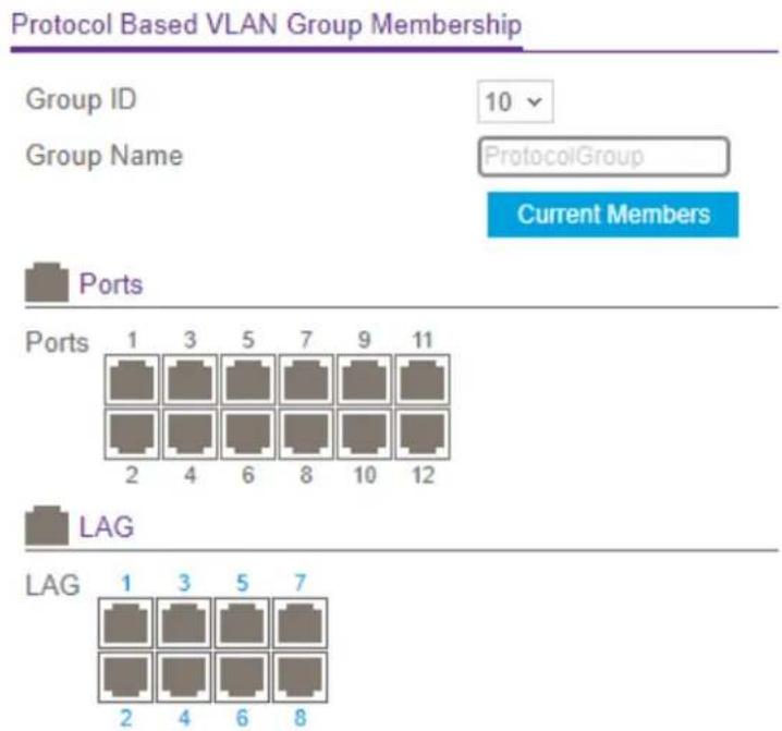
The previous gure shows the page for a model with 12 ports.
-
From the Group ID menu, select the protocol-based VLAN group ID. The Group Name eld shows the name for the protocol-based VLAN that you selected.
-
To display the current members of the selected protocol-based VLAN group, click the Current Members button.
A pop-up window displays the members.
-
To select physical interfaces for the VLAN, do one the following:
-
Select all physical interfaces: Click the Ports icon above the Ports table.
-
Select individual physical interfaces: In the Ports table, click one or more ports individually.
-
To select LAGs for the VLAN, do one the following:
-
Select all LAGs: Click the LAG icon above the LAG table.
-
Select individual LAGs: In the LAG table, click one or more LAGs individually.
-
Click the Apply button.
Your settings are saved.
- To save the settings to the running conguration, click the Save icon.
Congure an IP subnet-based VLAN
You configure an IP subnet-to-VLAN mapping by specifying a source IP address, network mask, and the VLAN ID. The IP subnet-to-VLAN congrurations are shared across all interfaces of the switch.
Add an IP subnet-based VLAN You can add an IP subnet-based VLAN. To add an IP subnet-based VLAN:
- Launch a web browser.
- In the address eld of your web browser, enter the IP address of the switch. The login page displays.
- Click the Main UI Login button.
The main UI login page displays in a new tab.
- Enter admin as the user name, enter your local device password, and click the Login button.
The rst time that you log in, no password is required. However, you then must specify a local device password to use each subsequent time that you log in.
The System Information page displays.
- Select Switching > VLAN > Advanced > IP Subnet Based VLAN.
The IP Subnet Based VLAN page displays.
- In the IP Address eld, specify an IP address.
Enter the IP address in dotted-decimal notation.
- In the Subnet Mask field, specify a subnet mask that is associated with the IP addre Enter the subnet mask in dotted-decimal notation.
- In the VLAN ID eld, specify the VLAN ID to which the IP conguration must be bound.
The VLAN ID can be in the range from 1 to 4093.
- Click the Add button.
The IP subnet-based VLAN is added.
- To save the settings to the running conguration, click the Save icon.
Delete an IP subnet-based VLAN You can delete an IP subnet-based VLAN that you no longer need.
To delete an IP subnet-based VLAN:
- Launch a web browser.
- In the address eld of your web browser, enter the IP address of the switch.
The login page displays.
- Click the Main UI Login button.
The main UI login page displays in a new tab.
- Enter admin as the user name, enter your local device password, and click the Login button.
The rst time that you log in, no password is required. However, you then must specify a local device password to use each subsequent time that you log in.
The System Information page displays.
- Select Switching> VLAN > Advanced > IP Subnet Based VLAN.
The IP Subnet Based VLAN page displays.
- Select the check box for the IP subnet-based VLAN.
- Click the Delete button.
The IP subnet-based VLAN is deleted.
- To save the settings to the running conguration, click the Save icon.
Congure a double VLAN
A double VLAN (DVLAN) lets you congregate an EtherType VLAN tag inside a VLAN tag. The EtherType VLAN tag can be an 802.1Q tag, virtual metropolitan area network (vMAN) tag, or custom tag.
To congregate the global EtherType for the DVLAN and congregate the DVLAN on one or more interfaces:
- Launch a web browser.
- In the address eld of your web browser, enter the IP address of the switch. The login page displays.
- Click the Main UI Login button.
The main UI login page displays in a new tab.
- Enter admin as the user name, enter your local device password, and click the Login button.
The rst time that you log in, no password is required. However, you then must specify a local device password to use each subsequent time that you log in.
The System Information page displays.
- Select Switching > VLAN > Advanced > Port DVLAN Conguration.
The Port DVLAN Conguration page displays.
-
From the Global EtherType menu, select a tag type that determines the rst 16 bits of the DVLAN tag:
-
802.1Q Tag: The dot1q tag that represents 0x8100.
- vMAN Tag: The virtual metropolitan area network (vMAN) tag that represents 0x88A8.
-
Custom Tag: A custom EtherType tag in the range from 0 to 65535. With this selection the Custom Value eld displays.
-
if you select Custom Tag from the Global EtherType menu, enter the custom EtherType tag in the Custom Value eld.
The tag can be in the range from 0 to 65535.
- Select whether to display physical interfaces, LAGs, or both by clicking one of the following links above the table heading:
• 1: Only physical interfaces are displayed. This is the default setting.
- LAG: Only LAGs are displayed.
- All: Both physical interfaces and LAGs are displayed.
-
Select one or more interfaces by taking one of the following actions:
-
To congregate a single interface, select the check box associated with the interface, or type the interface number in the Go To Interface eld and click the Go button.
- To congregate multiple interfaces with the same settings, select the check box associated with each interface.
AV Line of Fully Managed Switches M4250 Series Main User Manual
- To congregate all interfaces with the same settings, select the check box in the heading row.
- From the Admin Mode menu, select Enabled or Disabled to specify if the selected DVLAN tag is added to frames that are processed on the interface.
The default is Disabled and the selected DVLAN tag is not added to frames.
- Click the Apply button.
Your settings are saved.
- To save the settings to the running conguration, click the Save icon.
Congure a voice VLAN
You can congregate a voice VLAN for use with voice traffic. For example, enable the voice VLAN on an interface that is connected to IP phones. A voice VLAN can ensure that the sound quality of IP phone traffic remains good when data traffic on the same interface is high.
To congure a voice VLAN:
- Launch a web browser.
- In the address eld of your web browser, enter the IP address of the switch. The login page displays.
- Click the Main UI Login button.
The main UI login page displays in a new tab.
- Enter admin as the user name, enter your local device password, and click the Login button.
The rst time that you log in, no password is required. However, you then must specify a local device password to use each subsequent time that you log in.
The System Information page displays.
- Select Switching > VLAN > Advanced > Voice VLAN Conguration.
The Voice VLAN Conguration page displays.
- Select the Admin Mode Disable or Enable radio button to disable or enable the global voice VLAN mode on the switch.
The default is Disable. If you want to use a voice VLAN, you must enable the global voice VLAN mode.
-
Select one or more interfaces by taking one of the following actions:
-
To congregate a single interface, select the check box associated with the interface, or type the interface number in the Go To Interface eld and click the Go button.
- To congregate multiple interfaces with the same settings, select the check box associated with each interface.
-
To congregate all interfaces with the same settings, select the check box in the heading row.
-
From the Interface Mode menu, select the voice VLAN mode:
-
Disable: This is the default value.
- None: Allows an IP phone to use its own conguration to send untagged voice trafc.
- VLAN ID: An IP phone must be congured to send tagged voice trafc.
- Dot1p: Congure voice VLAN 802.1p priority tagging for voice traffic. If you select this mode, enter the dot1p value in the Value eld.
-
Untagged: An IP phone must be congured to send untagged voice trafc.
-
From the CoS Override Mode menu, select one of the following:
-
Enable: The interface ignores (that is, overrides) the 802.1p priority value in the Ethernet frames it receives from connected devices. The DSCP eld overrides the CoS value.
-
Disable: The interface trusts the priority value in the received frame. The default is Disable.
-
From the Authentication Mode menu, select one of the following:
-
Enable: Voice traffic is allowed on an unauthorized voice VLAN interface. The default is Enable.
-
Disable: Voice traffic is allowed only an authorized voice VLAN interface, for which dot1x must be enabled (see Manage port authentication on individual ports on page 554).
-
In the DSCP Value eld, congure the DSCP value for the interface.
The range is from 0 to 64. The default is 0.
- Click the Apply button.
Your settings are saved.
The Operational State eld displays the operational status of the voice VLAN on the interface.
- To save the settings to the running conguration, click the Save icon.
Congure Generic Attribute Registration Protocol
Generic Attribute Registration Protocol (GARP) allows network devices to share information such as VLAN IDs and multicast group membership across a bridged LAN. That is, GARP participants can register and deregister attribute values within the LAN. When a GARP participant declares or withdraws an attribute, the attribute value is recorded for that attribute and for the interface from which the declaration or withdrawal was made.
The following applies to GARP:
- Registration occurs only on interfaces that receive a GARP PDU with a declaration or withdrawal.
- Deregistration occurs only if all GARP participants that are connected to the same LAN segment as the interface withdraw the declaration.
Configure GARP switch settings You can globally enable GARP VLAN registration protocol (GVRP) and GARP multicast registration protocol (GMRP) on the switch.
To congure GARP switch settings:
- Launch a web browser.
-
In the address eld of your web browser, enter the IP address of the switch. The login page displays.
-
Click the Main UI Login button. The main UI login page displays in a new tab.
-
Enter admin as the user name, enter your local device password, and click the Login button. The rst time that you log in, no password is required. However, you then must specify a local device password to use each subsequent time that you log in. The System Information page displays.
-
Select Switching > VLAN > Advanced > GARP Switch Conguration. The GARP Switch Conguration page displays.
-
Select the GVRP Mode Disable or Enable radio button to disable or enable GARP VLAN registration protocol (GVRP) globally for the switch. If GVRP is enabled, the switch can share VLAN IDs with devices in the network. the The default is Disable.
-
Select the GMRP Mode Disable or Enable radio button to disable or enable GARP multicast registration protocol (GMRP) globally for the switch.
If GVMP is enabled, the switch can share multicast information with devices in the network. the The default is Disable.
- Click the Apply button.
Your settings are saved.
It can take up to 10 seconds for GARP conguration changes to take effect.
- To save the settings to the running conguration, click the Save icon.
Congure GARP settings for one or more interfaces You can congregate GARP settings for individual interfaces. These settings take effect only if GVRP mode, GMRP mode, or both modes are enabled on the switch.
To congure GARP settings for one or more interfaces:
- Launch a web browser.
- In the address eld of your web browser, enter the IP address of the switch. The login page displays.
- Click the Main UI Login button.
The main UI login page displays in a new tab.
- Enter admin as the user name, enter your local device password, and click the Login button.
The rst time that you log in, no password is required. However, you then must specify a local device password to use each subsequent time that you log in. The System Information page displays.
- Select Switching > VLAN > Advanced > GARP Port Conguration. The
The GARP Port Conguration page display.
- Select whether to display physical interfaces, LAGs, or both by clicking one of the following links above the table heading:
• 1: Only physical interfaces are displayed. This is the default setting.
- LAG: Only LAGs are displayed.
- All: Both physical interfaces and LAGs are displayed.
-
Select one or more interfaces by taking one of the following actions:
-
To congregate a single interface, select the check box associated with the interface, or type the interface number in the Go To Interface eld and click the Go button.
- To congregate multiple interfaces with the same settings, select the check box associated with each interface.
AV Line of Fully Managed Switches M4250 Series Main User Manual
- To congregate all interfaces with the same settings, select the check box in the heading row.
- From the GVRP Mode menu, select Enable or Disable to specify the GARP VLAN registration protocol mode for the port.
If you select Disable, GVRP is not active and the join time, leave time, and leave a time options are without any effect. The default is Disable.
- From the GMRP Mode menu, select Enable or Disable to specify the GARP multicast registration protocol mode for the port.
If you select Disable, GMRP is not active and the join time, leave time, and leave a time options are without any effect. The default is Disable.
- In the Join Timer eld, specify the time in centiseconds between the transmission of GARP PDUs registering membership for a VLAN or multicast group.
Enter a number between 10 and 100 (0.1 to 1.0 seconds). The default is 20 centiseconds (0.2 seconds). An instance of this timer exists for each GARP participant for each port.
- In the Leave Timer eld, specify the time in centiseconds to wait after receiving an unregister request for a VLAN or multicast group before deleting the associated entry.
This allows time for another station to assert registration for the same attribute to maintain uninterrupted service. Enter a number between 20 and 600 (0.2 to 6.0 seconds). The default is 60 centiseconds (0.6 seconds). An instance of this timer exists for each GARP participant for each port.
- In the Leave All Timer eld, specify how frequently (in centiseconds) LeaveAll PDUs are generated.
A LeaveAll PDU indicates that all registrations will be deregistered soon. To maintain registration, participants must rejoin. The leave all period timer is set to a random value in the range of LeaveAllTime to 1.5 * LeaveAllTime. The timer is specied in centiseconds. Enter a number between 200 and 6000 (2 to 60 seconds). The default is 1000 centiseconds (10 seconds). An instance of this timer exists for each GARP participant for each port.
- Click the Apply button.
Your settings are saved.
It can take up to 10 seconds for GARP congruration changes to take effect.
- To save the settings to the running conguration, click the Save icon.
Auto-VolP
Voice over Internet Protocol (VoIP) enables telephone calls over a data network. Because voice trafc is typically more time-sensitive than data trafc, Auto-VoIP provides classification for voice packets so that they can be prioritized above data packets for better quality of service (QoS). With Auto-VoIP, voice prioritization is based on call-control protocols such as SIP, H.323, and SCCP on interfaces or organizationally unique Identifier (OUI) bits.
Congure Auto-VoIP protocol-based settings
To prioritize time-sensitive voice trafc over data trafc, protocol-based Auto-VoIP determines if packets carry the following VoIP protocols:
- Session Initiation Protocol (SIP)
H.323
• Signalling Connection Control Part (SCCP)
VoIP packets that come in on an interface on which Auto-VoIP is enabled are marked with the specied CoS trafc class value.
To congregate protocol-based settings for one or more interfaces:
- Launch a web browser.
- In the address eld of your web browser, enter the IP address of the switch. The login page displays.
- Click the Main UI Login button.
The main UI login page displays in a new tab.
- Enter admin as the user name, enter your local device password, and click the Login button.
The rst time that you log in, no password is required. However, you then must specify a local device password to use each subsequent time that you log in.
The System Information page displays.
- Select Switching > Auto-VoIP > Protocol-based > Port Settings.
The Port Settings page displays.
- In the Protocol Based Global Settings section, specify the following global settings:
a. From the Prioritization Type menu, select Trafc Class or Remark.
This species the type of prioritization.
b. From the Class Value menu, specify the CoS class value to be reassigned for packets that the voice VLAN receives.
You can select a value in the range from 0 to 7.
- In the Protocol Based Global Settings section, specify the Auto VoIP settings for the interfaces:
a. Select whether to display physical interfaces, LAGs, or both by clicking one of the following links above the table heading:
• 1: Only physical interfaces are displayed. This is the default setting.
• LAG: Only LAGs are displayed.
- All: Both physical interfaces and LAGs are displayed.
b. Select one or more interfaces by taking one of the following actions:
- To congregate a single interface, select the check box associated with the port, or type the port number in the Go To Interface eld and click the Go button.
- To congregate multiple interfaces with the same settings, select the check box associated with each interface.
- To congregate all interfaces with the same settings, select the check box in the heading row.
c. From the Auto VoIP Mode menu, select to enable or disable the Auto VoIP mode for the interface.
Auto-VoIP is disabled by default.
- Click the Apply button.
Your settings are saved.
The Operational Status eld show if the interface is up or down.
- To save the settings to the running conguration, click the Save icon.
Congure the Auto-VolP OUI-based properties
With organizationally unique Identier (OUI)-based Auto-VoIP, voice prioritization is provided based on OUI bits.
To congregate the Auto-VoIP OUI-based properties:
- Launch a web browser.
-
In the address eld of your web browser, enter the IP address of the switch. The login page displays.
-
Click the Main UI Login button. The main UI login page displays in a new tab.
-
Enter admin as the user name, enter your local device password, and click the Login button. The rst time that you log in, no password is required. However, you then must specify a local device password to use each subsequent time that you log in. The System Information page displays.
-
Select Switching > Auto-VoIP > OUI-based > Properties. The Properties page displays.
-
In the Auto-VoIP VLAN ID eld, enter the VoIP VLAN ID of the switch. No default VLAN exists for Auto-VoIP, you must create a VLAN for Auto-VoIP.
-
From the OUI-based priority menu, select the OUI-based priority of the switch. The default value is 7.
-
Click the Apply button. Your settings are saved.
-
To save the settings to the running conguration, click the Save icon.
Congure the OUI-based interface settings
You can congregate the OUI interface settings.
To congregate the OUI-based interface settings:
- Launch a web browser.
-
In the address eld of your web browser, enter the IP address of the switch. The login page displays.
-
Click the Main UI Login button. The main UI login page displays in a new tab.
-
Enter admin as the user name, enter your local device password, and click the Login button.
The rst time that you log in, no password is required. However, you then must specify a local device password to use each subsequent time that you log in.
The System Information page displays.
- Select Switching > Auto-VoIP > OUI-based > Port Settings.
The page Port Settings displays.
- Select whether to display physical interfaces, LAGs, or both by clicking one of the following links above the table heading:
• 1: Only physical interfaces are displayed. This is the default setting.
- LAG: Only LAGs are displayed.
- All: Both physical interfaces and LAGs are displayed.
-
Select one or more interfaces by taking one of the following actions:
-
To congregate a single interface, select the check box associated with the port, or type the port number in the Go To Interface eld and click the Go button.
- To congregate multiple interfaces with the same settings, select the check box associated with each interface.
-
To congregate all interfaces with the same settings, select the check box in the heading row.
-
From the Auto VoIP Mode menu, select to enable or disable the Auto VoIP mode for the interface.
Auto-VolP is disabled by default.
- Click the Apply button.
Your settings are saved.
The Operational Status eld show if the interface is up or down.
- To save the settings to the running conguration, click the Save icon.
Manage the OUI table
Device hardware manufacturers can include an OUI in a network adapter to help identify a hardware device. The OUI is a unique 24-bit number assigned by the IEEE registratic authority. The switch comes precongured with the following OUIs that identify the IP phone manufacturer:
• 00:01:E3: SIEMENS
• 00:03:6B: CISCO1
• 00:12:43: CISCO2
00:0F:E2: H3C
• 00:60:B9: NITSUKO
• 00:D0:1E: PINTEL
• 00:E0:75: VERILINK
00:E0:BB: 3COM
• 00:04:0D: AVAYA1
• 00:1B:4F: AVAYA2
• 00:04:13: SNOM
• 00:1D:C1: Dante
You can select an existing OUI or add a new OUI and description to identify the IP phones on the network.
Add an OUI prex To add an OUI prex:
- Launch a web browser.
-
In the address eld of your web browser, enter the IP address of the switch. The login page displays.
-
Click the Main UI Login button. The main UI login page displays in a new tab.
-
Enter admin as the user name, enter your local device password, and click the Login button. The rst time that you log in, no password is required. However, you then must specify a local device password to use each subsequent time that you log in. The System Information page displays.
-
Select Switching > Auto-VoIP > OUI-based > OUI Table. The OUI Table page displays.
-
In the Telephony OUI(s) eld, specify the new VoIP OUI prex in the format AA:BB:CC. The table can include up to 128 OUIs.
-
In the Description eld, enter the description for the OUI. The maximum length is 32 characters.
-
Click the Add button. The telephony OUI entry is added.
-
To save the settings to the running conguration, click the Save icon.
Delete one or more OUI prexes To delete one or more OUI prexes:
- Launch a web browser.
- In the address eld of your web browser, enter the IP address of the switch. The login page displays.
- Click the Main UI Login button. The main UI login page displays in a new tab.
- Enter admin as the user name, enter your local device password, and click the Login button. The rst time that you log in, no password is required. However, you then must specify a local device password to use each subsequent time that you log in. The System Information page displays.
- Select Switching > Auto-VoIP > OUI-based > OUI Table. The OUI Table page displays.
- Select the check box next to each OUI prex to be removed.
- Click the Delete button. The telephony OUI entries are removed.
- To save the settings to the running conguration, click the Save icon.
Display the Auto-VoIP status
To display the Auto-VoIP status:
- Launch a web browser.
-
In the address eld of your web browser, enter the IP address of the switch. The login page displays.
-
Click the Main UI Login button. The main UI login page displays in a new tab.
-
Enter admin as the user name, enter your local device password, and click the Login button. The rst time that you log in, no password is required. However, you then must specify a local device password to use each subsequent time that you log in. The System Information page displays.
-
Select Switching > Auto-VoIP > Auto-VoIP Status.
The Auto-VoIP Status page displays.
- To refresh the page, click the Refresh button.
The following table describes the noncongorable elds on the page.
Table 55. Auto-VoIP status information
| DescriptionField | |
| The Auto-VoIP VLAN ID.Auto-VoIP VLAN ID | |
| Channels Supported | The maximum number of voice channels supported.Maximum Number of Voice |
| Detected | The number of VoIP channels prioritized successfully.Number of Voice Channels |
Spanning Tree Protocol
The Spanning Tree Protocol (STP) provides a tree topology for any arrangement of network devices. STP also provides one path between end stations on a network, eliminating loops. STP (also referred to as "classic" STP) provides a single path between end stations, avoiding and eliminating loops. For information about conguring the global STP settings for the switch, see Congure the STP settings and display the STP status on page 226.
The switch support the following spanning tree versions:
- CST: Common STP. For information about conguring CST, see Congure the CST settings and display the CST status on page 229 and Congure the CST interface settings on page 231.
- MSTP: Multiple Spanning Tree Protocol (MSTP, also referred to as MST) supports multiple instances of spanning tree to efficiently channel VLAN traffic over different interfaces. For information about conguring MSTP, see Manage MST instances on page 236 and Congure and display the interface settings for an MST instance on page 239.
- RSTP: Rapid STP. Each instance of the spanning tree behaves in the manner specified in IEEE 802.1w, Rapid Spanning Tree (RSTP), with slight modifications in the working but not the end effect (the main effect is the rapid transitioning of the port to the forwarding state).
The difference between the RSTP and the traditional STP (IEEE 802.1D) is the ability to congregate and recognize full-duplex connectivity and ports that are connected to end stations, resulting in rapid transitioning of the port to the forwarding state and the suppression of Topology Change Notification messages. These features are represented by the 'pointtopoint' and 'edgeport' parameters. MSTP is compatible with both RSTP and STP. It behaves in a way that is appropriate for STP and RSTP bridges. An MSTP bridge can be congrouped to behave entirely as an RSTP bridge or an STP bridge.
- PVST: Per-VLAN Spanning Tree (PVST) provides a unique instance of spanning tree for each VLAN. For information about conguring PVTP, see Congure the PVST/RPVST VLAN settings on page 243 and Configure the PVST and RPVST interface settings on page 246.
- RPVST: Rapid Per-VLAN Spanning Tree (RPVST) provides a unique instance of spanning tree for each VLAN with each instance behaving in the manner specified in IEEE 802.1w, Rapid Spanning Tree (RSTP). Compared to PVST, RPVST provides a faster spanning tree convergence in response to Layer 2 topology changes. For information about conguring RPVTP, see Congure the PVST/RPVST VLAN settings on page 243 and Congure the PVST and RPVST interface settings on page 246.
Note: For two bridges to be in the same region, the force version must be 802.1s an their conguration names, digest keys, and revision levels must match. For additional information about regions and their effect on network topology, refer to the IEEE 802.1C standard.
Congure the STP settings and display the STP status
You can congregate the Spanning Tree Protocol (STP) settings and display the STP status on the switch.
To congregate the STP settings and display the STP status:
- Launch a web browser.
-
In the address eld of your web browser, enter the IP address of the switch. The login page displays.
-
Click the Main UI Login button.
The main UI login page displays in a new tab.
- Enter admin as the user name, enter your local device password, and click the Login button.
The rst time that you log in, no password is required. However, you then must specify a local device password to use each subsequent time that you log in.
The System Information page displays.
- Select Switching > STP > Basic > STP Conguration.
The STP Conguration page displays.
- Select the Spanning Tree Admin Mode Disable or Enable radio button.
This species whether spanning tree operation is enabled on the switch.
-
Select one of the following Force Protocol Version radio buttons to specify the STP version that the switch must use:
-
IEEE 802.1d: Traditional (classic) Spanning Tree Protocol.
- IEEE 802.1w: Rapid Spanning Tree Protocol.
• PVST: Per-VLAN Spanning Tree Protocol. -
RPVST: Rapid Per-VLAN Spanning Tree Protocol.
-
In the Conguration Name eld, specify an ID or name that lets you identify the conguration.
The name can be up to 32 characters. The default is the MAC address of the switch
- In the Conguration Revision Level eld, specify an ID that lets you identify the conguration.
For example, if you change the conguration, you can change the ID in the Conguration Revision Level eld so you can keep track of the different congurations. You can enter an ID from 0 to 65535. The default is 0.
-
Select one of the following Forward BPDU while STP Disabled radio buttons:
-
Disabled: Spanning tree BPDUs are not forwarded if spanning-tree is disabled on the switch. The default is Disable.
-
Enabled: Spanning tree BPDUs are forwarded if spanning-tree is disabled on the switch.
-
Select one of the following BPDU Guard radio buttons:
-
Disabled: The BPDU guard feature is disabled, which is the default setting.
-
Enabled: The BPDU guard feature is enabled and enforces the STP domain borders to keep the active topology consistent and predictable. Switches behind edge ports on which STP BPDU guard is enabled do not affect the overall STP topology. At the reception of BPDUs, the port on which BPDU guard is enabled transitions into disabled state.
-
Select one of the following BPDU Filter radio buttons:
- Disabled: The BPDU Filter feature is disabled, which is the default setting.
- Enabled: The BPDU Filter feature is enabled and applies to all operational edge ports. An edge port in an operational state connects to hosts that typically drop BPDUs. If an operational edge port receives a BPDU, it loses its operational status. If a port on which BPDU ltering is enabled receives BPDUs, the port drops the BPDUs and remains operational.
-
If you selected the PVST radio button in Step 7, select one of the following Fast Backbone radio buttons:
-
Disabled: The Fast Backbone feature is disabled, which is the default setting.
-
Enabled: The Fast Backbone feature is enabled. If an indirect link fails, the switch can automatically select a new indirect link. With PVST, the switch does not ignore inferior BPDUs (which occurs with STP), but lets the BPDUs time-out on the port where they were received. Then, the switch sends root link queries on other non-designated ports. If the switch receives a positive response, it selects a new indirect link.
-
If you selected the PVST radio button in Step 7, select one of the following Fast Uplink radio buttons:
-
Disabled: The Fast Uplink feature is disabled, which is the default setting.
-
Enabled: The Fast Uplink feature is enabled. If the primary root port goes down, the recovery time in selecting a new root port is reduced.
-
If you enabled Fast Uplink in the previous step, in the Max Update Rate eld, enter the maximum update rate in packets per second.
You enter from 0 to 32000 packets per second. The default is 150.
- Click the Apply button.
Your settings are saved.
- To save the settings to the running conguration, click the Save icon.
The following table describes the noncongorable elds on the page.
Table 56. STP congruration and status information
| DescriptionField | |
| STP Conguration | |
| The identifier for the STP conguration.Conguration Digest Key | |
| The version of the conguration format for the exchange of BPDUs.Configuration Format S | |
| STP Status | |
Table 56. STP conguration and status information (Continued)
| DescriptionField |
| The multiple spanning tree (MST) or common spanning tree (CST) instance.MST ID |
| The VLAN ID (VID).VID ID |
| The Itering ID (FID).FID ID |
Congure the CST settings and display the CST status
You can congregate common spanning tree (CST) and display the CST status on the switch.
To congregate the CST settings and display the CST status:
- Launch a web browser.
-
In the address eld of your web browser, enter the IP address of the switch. The login page displays.
-
Click the Main UI Login button. The main UI login page displays in a new tab.
-
Enter admin as the user name, enter your local device password, and click the Login button. The rst time that you log in, no password is required. However, you then must specify a local device password to use each subsequent time that you log in. The System Information page displays.
-
Select Switching > STP > Advanced > CST Conguration. The CST Conguration page displays.
-
In the Bridge Priority field, specify the bridge priority value for the common spanning tree (CST) and common and internal spanning tree (CIST). The range is from 0 to 61440. The bridge priority is a multiple of 4096. The default priority is 32768. When switches or bridges are running STP, each is assigned a priority. After exchanging BPDUs, the switch with the lowest priority value becomes the root bridge. If you specify a priority that is not a multiple of 4096, the priority is automatically set to the next lowest priority that is a multiple of 4096. For example, if you set the priority to a value between 0 and 4095, it is automatically set to 0.
-
In the Bridge Max Age (secs) eld, specify the period in seconds that a bridge wait before implementing a topological change.
The range is from 6 to 40 seconds, and the value must be less than or equal to t following: (2 * Bridge Forward Delay) - 1 and greater than or equal to 2 * (Bridge Hello Time +1).
The default is 20 seconds.
Note: The Bridge Hello Time (secs) eld shows the xed period in seconds that a root bridge waits between conguration messages. The xed period is 2 seconds.
- In the Bridge Forward Delay (secs) field, specify the period in seconds that a bridge remains in a listening and learning state before forwarding packets.
The period is form 4 to 30 seconds, and the value must be greater or equal to the following: (Bridge Max Age / 2) + 1.
The default is 15 seconds.
- In the Spanning Tree Maximum Hops field, specify the maximum number of bridge hops that the information for a particular CST instance can travel before being discarded.
The range is from 6 to 40 hops. The default is 20 hops.
- In the Spanning Tree Tx Hold Count eld, specify the maximum number of BPDUs that the bridge can send within the hello time window.
The range is from 1 to 10. The default is 6.
- Click the Apply button.
Your settings are saved.
- To save the settings to the running conguration, click the Save icon.
The following table describes the noncongorable elds on the page.
Table 57. CST status information
| DescriptionField | |
| Bridge identifier | The bridge identifier for the CST, which consist of the bridge priority and the base MAC address of the bridge. |
| The time in seconds since the topology of the CST changed.Time Since Topology CI | |
| The number of times the topology changed for the CST.Topology Change Count | |
| Topology Change | This eld shows if a topology change is in progress on any port assigned to the CST. (True or False.) |
| Designated Root | The bridge identifier of the root bridge, which consist of he bridge priority and the base MAC address of the bridge. |
| The path cost to the designated root for the CST.Root Path Cost | |
| The port through which the designated root for the CST is accessed.Root Port | |
| Max Age (secs) | The period in seconds that passes before a bridge port saves its conguration BPDU information. |
| Forward Delay (secs) | The period in seconds that the root port bridge delays the forwarding process. This period is a derived value. |
| The minimum period between the transmission of conguration BPDUs.Hold Time (secs | |
| The priority and base MAC address of the CST regional root.CST Regional Root | |
| The path cost to the CST regional root.CST Path Cost | |
| The port on which the topology change (TC) is triggered,Port Triggered TC |
Congure the CST interface settings
You can congregate a common spanning tree (CST) and internal spanning tree on a specific interface on the switch.
An interface can become diagnostically disabled (D-Disable) when a severe error condition occurs for DOT1S. The most common cause is when BPDU ooding occurs. The ooding criteria are such that DOT1S receives more than 15 BPDUs in a 3-second interval. (Other causes for a DOT1S D-Disable condition are very rare.)
To congregate the CST interface settings:
- Launch a web browser.
- In the address eld of your web browser, enter the IP address of the switch. The login page displays.
-
Click the Main UI Login button. The main UI login page displays in a new tab.
-
Enter admin as the user name, enter your local device password, and click the Login button. The rst time that you log in, no password is required. However, you then must specify a local device password to use each subsequent time that you log in. The System Information page displays.
-
Select Switching > STP > Advanced > CST Port Conguration.
The CST Port Conguration page displays.
- Select whether to display physical interfaces, LAGs, or both by clicking one of the following links above the table heading:
• 1: Only physical interfaces are displayed. This is the default setting.
- LAG: Only LAGs are displayed.
- All: Both physical interfaces and LAGs are displayed.
-
Select one or more interfaces by taking one of the following actions:
-
To congregate a single interface, select the check box associated with the port, or type the port number in the Go To Interface eld and click the Go button.
- To congregate multiple interfaces with the same settings, select the check box associated with each interface.
-
To congregate all interfaces with the same settings, select the check box in the heading row.
-
In the Port Priority eld, specify the priority for the port in the CST.
Specify the port priority in multiples of 16. For example, if you set the port priority to a value between 0 and 15, it is automatically set to 0. if you set the port priority a value between 16 and (2*16-1), it is automatically set to 16, and so on. The defa is 128.
- From the Admin Edge Port menu, select Enable or Disable to specify if the port functions as an edge port in the CIST.
The default is Disable.
-
In the Port Path Cost eld, specify a path cost value for the port in the CIST The value can be in the range from 1 to 200000000. The default is 0.
-
From the Auto Calculated Port Path Cost menu, select Enable or Disable to specify if the external path cost is calculated automatically.
If the value in the Port Path Cost eld is zero and the path cost is calculated automatically, the value is based on the link speed of the port.
The default is Disable.
- In the External Port Path Cost eld, specify an external path cost value for the port in the CIST.
The value can be in the range from 1 to 200000000. The default is 0.
- From the Auto Calculated External Port Path Cost menu, select Enable or Disable to specify if the external path cost is calculated automatically.
AV Line of Fully Managed Switches M4250 Series Main User Manual
If the value in the External Port Path Cost eld is zero and the external path cost calculated automatically, the value is based on the link speed of the port.
The default is Disable.
- From the BPDU Filter menu, select Enable or Disable to specify if BPDU trafc is itered on the port when STP is enabled on the port.
The default value is Disable.
- From the BPDU Forwarding menu, select Enable or Disable to specify if BPDU trafc that arrives on the port can be ooded if STP is disabled on the port.
The default value is Disable.
- From the Auto Edge menu, select Enable or Disable to specify if the port can become an edge port if the port does not receive BPDUs for a period.
The default is Enable.
- From the Root Guard menu, select Enable or Disable to specify if the port can discard any superior information that it receives and, in this way, protect the root of the device from changing.
If you enable this option, the port is placed in the discarding state and does not forward any packets. The default value is Disable.
- From the Loop Guard menu, select Enable or Disable to specify if the port is protected from Layer 2 forwarding loops.
If you enable this option, the port moves from the 'listening/learning/forwarding' state to the 'STP loop inconsistent blocking state.' The default is Disable
- From the TCN Guard menu, select Enable or Disable to specify if the port is restricted from propagating any topology change information that it receives.
The default is Disable.
- From the Port Mode menu, select Enable or Disable to specify if the STP is enabled or disabled on the port.
The default value is Disable.
- Click the Apply button.
Your settings are saved.
- To save the settings to the running conguration, click the Save icon.
The following table describes the noncongorable elds on the page.
Table 58. CST port conguration information
| DescriptionField | |
| The setting of the Hello Timer for the CST. By default, the setting is 2.Hello Timer | |
| Indicates if an edge port that receives BPDU packets is enabled or disabled.BPDU Guard | |
| Port Forwarding State | Indicates the current STP state of the interface. If enabled, the port state determines what forwarding action is taken on trafc. Possible port states are as follows:Disabled:STP is currently disabled on the interface. The interface forwards trafc while learning MAC addresses.Blocking:The interface is currently blocked and cannot be used to forward trafc or learn MAC addresses.Listening:The interface is currently in the listening mode. The interface cannot forward trafc nor can it learn MAC addresses.Learning:The interface is currently in the learning mode. The interface cannot forward trafc. However, it can learn new MAC addresses.Forwarding:The interface is currently in the forwarding mode. The interface can forward trafc and learn new MAC addresses |
Display the CST interface Status
You can display the Common Spanning Tree (CST) status information for interfaces on the switch.
To display the CST interface status:
- Launch a web browser.
- In the address eld of your web browser, enter the IP address of the switch. The login page displays.
- Click the Main UI Login button.
The main UI login page displays in a new tab.
- Enter admin as the user name, enter your local device password, and click the Login button.
The rst time that you log in, no password is required. However, you then must specify a local device password to use each subsequent time that you log in.
The System Information page displays.
- Select Switching > STP > Advanced > CST Port Status.
The CST Port Status page displays.
-
Select whether to display physical interfaces, LAGs, or both by clicking one of the following links above the table heading:
-
1: Only physical interfaces are displayed. This is the default setting.
- LAG: Only LAGs are displayed.
-
All: Both physical interfaces and LAGs are displayed.
-
To refresh the page, click the Refresh button.
The following table describes the noncongorable elds on the page.
Table 59. CST interface status information
| DescriptionField | |
| The physical interface or LAG that is associated with the CST.Interface | |
| Port ID | The port identifier for port in the CST, which is created from the port priority and the interface number. |
| Port Forwarding State | Indicates the current STP state of the interface. If enabled, the port state determines what forwarding action is taken on trafc. Possible port states are as follows:Disabled:STP is currently disabled on the interface. The interface forwards trafc while learning MAC addresses.Blocking:The interface is currently blocked and cannot be used to forward trafc or learn MAC addresses.Listening:The interface is currently in the listening mode. The interface cannot forward trafc nor can it learn MAC addresses.Learning.The interface is currently in the learning mode. The interface cannot forward trafc. However, it can learn new MAC addresses.Forwarding:The interface is currently in the forwarding mode. The interface can forward trafc and learn new MAC addresses |
| Port Role | Each MST bridge port that is enabled is assigned a port role for each spanning tree. The port role is one of the following: Root, Designated, Alternate, Backup, Master, or Disabled. |
| Designated Root | The root bridge for the CST, which is created from the bridge priority and the base MAC address of the bridge. |
| The path cost offered to the LAN by the designated port. Designated Cost | |
| Designated Bridge | The bridge identifier of the bridge with the designated port. This identifier is created from the bridge priority and the base MAC address of the bridge. |
| Designated Port | The port identifier on the designated bridge that offers the lowest cost to the LAN. This identifier is created from the port priority and the interface number of the port. |
| DescriptionField | |
| Topology Change Acknowledge Indicates if the topology change acknowledgement ag is set for the next BPDU to be transmitted on the port. (True or False.) | |
| Indicates if the port is enabled as an edge port.Edge port | |
| Point-to-Point MAC | The point-to-point status, which indicates is the port's link is a point-to-point link (True) or not or (False). |
| CST Regional Root | The bridge identier of the CST regional root. This identier is created from the bridge priority and the base MAC address of the bridge. |
| The path cost to the CST regional root.CST Path Cost | |
| Cleared | The the time the counters were last cleared.Port Up Time Since Counters Last |
| Indicates if the interface is in a loop-inconsistent state. (False or True.)Loop Inconsist | |
| Transitions Into Loop Inconsistent State | The number of times the interface transitioned into the loop-inconsistent state. |
| Transitions Out Of Loop Inconsistent State | The number of times the interface transitioned out of the loop-inconsistent state. |
Manage MST instances
You can add, change, or delete multiple spanning tree (MST) instances on the switch.
The MST instance consists of an ID, a priority value, and a VLAN ID.
Add an MST instance and display the MST status You can add an MST insta and display the MST status.
To add an MST instance and display the MST status:
- Launch a web browser.
-
In the address eld of your web browser, enter the IP address of the switch.
The login page displays. -
Click the Main UI Login button.
The main UI login page displays in a new tab.
- Enter admin as the user name, enter your local device password, and click the Login button.
The rst time that you log in, no password is required. However, you then must specify a local device password to use each subsequent time that you log in.
The System Information page displays.
5. Select Switching > STP > Advanced > MST Conguration.
The MST Conguration page display.
6. Congure the settings for the MST instance:
- MST ID: In the MST ID eld, specify the ID of the MST. The ID can be in the range from 1 to 4094.
- Priority: In the Priority field, specify the bridge priority value for the MST instance. When switches or bridges are running STP, each is assigned a priority. After exchanging BPDUs, the switch with the lowest priority value becomes the root bridge. The bridge priority is a multiple of 4096. If you specify a priority that is a multiple of 4096, the priority is automatically set to the next lowest priority that is a multiple of 4096. For example, if you set the priority to any value between 0 and 4095, the switch automatically sets the value to 0. The range is from 0 to 61440. The default is 32768.
- VLAN ID: From the VLAN ID menu, select the VLAN that must be associated with the MST instance.
7. Click the Add button
The MST is added.
- To save the settings to the running conguration, click the Save icon.
- To refresh the page, click the Refresh button.
The following table describes the noncongorable elds on the page.
Table 60. MST conguration information
| DescriptionField | |
| Bridge Identifier | The bridge identifier for the MST instance, which is created by using the bridge priority and the base MAC address of the bridge. |
| The time in seconds since the topology of the MST instance changed.Last TCN | |
| The number of times the topology changed for the MST instance.Topology Change Cou | |
| Topology Change | This eld shows if a topology change is in progress on an interface in the MST. (True or False.) |
| Designated Root | The bridge identifier of the root bridge, which is created by using the bridge priority and the base MAC address of the bridge |
Table 60. MST conguration information (Continued)
| DescriptionField |
| The path cost to the designated root for the MST instance.Root Path Cost |
| The port through which the designated root for the MST instance can be accessed.Root |
Change an MST instance You can change an existing MST instance. To change an existing MST instance:
- Launch a web browser.
- In the address eld of your web browser, enter the IP address of the switch. The login page displays.
- Click the Main UI Login button. The main UI login page displays in a new tab.
-
Enter admin as the user name, enter your local device password, and click the Login button. The rst time that you log in, no password is required. However, you then must specify a local device password to use each subsequent time that you log in. The System Information page displays.
-
Select Switching > STP > Advanced > MST Conguration. The MST Conguration page display.
-
Select the check box that is associated with the MST instance.
-
Change the settings as needed. For more information, see Add an MST instance and display the MST status on page 236.
-
Click the Apply button. Your settings are saved.
-
To save the settings to the running conguration, click the Save icon.
Delete an MST instance You can delete an MST instance that you no longer need To delete an MST instance:
- Launch a web browser.
-
In the address eld of your web browser, enter the IP address of the switch. The login page displays.
-
Click the Main UI Login button.
The main UI login page displays in a new tab.
- Enter admin as the user name, enter your local device password, and click the Login button.
The rst time that you log in, no password is required. However, you then must specify a local device password to use each subsequent time that you log in.
The System Information page displays.
- Select Switching > STP > Advanced > MST Conguration.
The MST Conguration page display.
-
Select the check box that is associated with the MST instance.
-
Click the Delete button.
The MST instance is deleted.
- To save the settings to the running conguration, click the Save icon.
Congure and display the interface settings for an MSI instance
You can congregate and display the Multiple Spanning Tree (MST) settings on a specific interface on the switch.
An interface can become diagnostically disabled (D-Disable) when a severe error condition occurs for DOT1S. The most common cause is when BPDU ooding occurs. The ooding criteria are such that DOT1S receives more than 15 BPDUs in a 3-second interval. (Other causes for a DOT1S D-Disable condition are very rare.)
To congure and display the port settings for an MST instance:
-
Launch a web browser.
-
In the address eld of your web browser, enter the IP address of the switch. The login page displays.
-
Click the Main UI Login button.
The main UI login page displays in a new tab.
- Enter admin as the user name, enter your local device password, and click the Login button.
The rst time that you log in, no password is required. However, you then must specify a local device password to use each subsequent time that you log in.
The System Information page displays.
- Select Switching > STP > Advanced > MST Port Conguration.
The MST Port Conguration page displays.
- From the Select MST menu, select an MST instance.
For information about adding MST instances, see Manage MST instances on page 236.
- Select whether to display physical interfaces, LAGs, or both by clicking one of the following links above the table heading:
• 1: Only physical interfaces are displayed. This is the default setting.
- LAG: Only LAGs are displayed.
- All: Both physical interfaces and LAGs are displayed.
-
Select one or more interfaces by taking one of the following actions:
-
To congregate a single interface, select the check box associated with the port, or type the port number in the Go To Interface eld and click the Go button.
- To congregate multiple interfaces with the same settings, select the check box associated with each interface.
-
To congregate all interfaces with the same settings, select the check box in the heading row.
-
Congure the MST values for the selected interface or interfaces:
-
Port Priority: In the Port Priority eld, specify the priority for the interface in the MST instance. The port priority is set in multiples of 16. If you specify a value that is not a multiple of 16, the priority is automatically set to the next lowest priority that is a multiple of 16. For example, if you set a value between 0 and 15, the priority is set to 0. If you specify a number between 16 and 31, the priority is set to 16. Specify a value in the range from 0 to 240. The default is 128.
-
Port Path Cost: In the Port Path Cost eld, specify the path cost in the range from 0 to 200000000. The default is 0.
-
Click the Apply button.
Your settings are saved.
-
To save the settings to the running conguration, click the Save icon.
-
To refresh the page, click the Refresh button.
The following table describes the noncongorable elds on the page.
Table 61. MST interface conguration information
| DescriptionField | |
| The path cost that the interface uses.Operational Port Path Cost | |
| Auto Calculated Port Path Cost | Indicates if the path cost is automatically calculated (Enable) or not (Disable). If enabled, the path cost is calculated based on the link speed of the port if the congured value for Port Path Cost is zero. |
| Port ID | The port identifier for the port in the MST instance, which is created by using the port priority and the interface number. |
| Counters | The time since the counters were cleared.Port Uptime Since Last Clear |
| Indicates if STP is enabled for the interface.Port Mode | |
| Port Forwarding State | Indicates the current STP state of the interface. If enabled, the port state determines what forwarding action is taken on trafc. Possible port states are as follows:Disabled:STP is currently disabled on the interface. The interface forwards trafc while learning MAC addresses.Blocking:The interface is currently blocked and cannot be used to forward trafc or learn MAC addresses.Listening:The interface is currently in the listening mode. The interface cannot forward trafc nor can it learn MAC addresses.Learning:The interface is currently in the learning mode. The interface cannot forward trafc. However, it can learn new MAC addresses.Forwarding:The interface is currently in the forwarding mode. The interface can forward trafc and learn new MAC addresses |
| Port Role | Each MST bridge port that is enabled is assigned a port role for each spanning tree. The port role is one of the following: Root, Designated, Alternate, Backup, Master, or Disabled. |
| Designated Root | The bridge identifier of the root bridge, which is created by using the bridge priority and the base MAC address of the bridge |
| The path cost offered to the LAN by the designated port. Designated Cost | |
| DescriptionField | |
| Designated Bridge | The bridge identifier of the bridge with the designated port. This identifier is created from the bridge priority and the base MAC address of the bridge. |
| Designated Port | The port identifier on the designated bridge that offers the lowest cost to the LAN. This identifier is created from the port priority and the interface number of the port. |
| Indicates if the interface is in a loop-inconsistent state. (False or True.)Loop Incon | |
| Transitions Into Loop Inconsistent State | The number of times the interface transitioned into the loop-inconsistent state. |
| Transitions Out Of Loop Inconsistent State | The number of times the interface transitioned out of the loop-inconsistent state. |
Display the STP interface statistics
You can display information about the number and type of bridge protocol data units (BPDUs) that are transmitted and received on each interface.
To display the STP interface statistics:
- Launch a web browser.
-
In the address eld of your web browser, enter the IP address of the switch. The login page displays.
-
Click the Main UI Login button. The main UI login page displays in a new tab.
-
Enter admin as the user name, enter your local device password, and click the Login button.
The rst time that you log in, no password is required. However, you then must specify a local device password to use each subsequent time that you log in. The System Information page displays.
- Select Switching > STP > Advanced > STP Statistics.
The STP Statistics page displays.
- Select whether to display physical interfaces, LAGs, or both by clicking one of the following links above the table heading:
• 1: Only physical interfaces are displayed. This is the default setting.
- LAG: Only LAGs are displayed.
- All: Both physical interfaces and LAGs are displayed.
Your settings are saved.
- To refresh the page, click the Refresh button.
The following table describes the noncongorable elds on the page.
Table 62. STP interface statistics information
| DescriptionField |
| The number of STP BPDUs received on the interface.STP BPDUs Received |
| The number of STP BPDUs transmitted from the interfaceSTP BPDUs Transmitted |
| The number of RSTP BPDUs received on the interface.RSTP BPDUs Received |
| The number of RSTP BPDUs transmitted from the interface.RSTP BPDUs Transmitted |
| The number of MSTP BPDUs received on the interface.MSTP BPDUs Received |
| The number of MSTP BPDUs transmitted from the interface.MSTP BPDUs Transmitted |
Congure the PVST/RPVST VLAN settings
You can configure the Per-VLAN Spanning Tree Protocol (PVST) and Rapid PVST (RPVST) settings for a VLAN.
PVST and RPVST must be enabled. For more information, see Configure the STP settings and display the STP status on page 226.
To congregate the PVST/RPVST VLAN settings for the switch:
- Launch a web browser.
-
In the address eld of your web browser, enter the IP address of the switch. The login page displays.
-
Click the Main UI Login button.
The main UI login page displays in a new tab.
- Enter admin as the user name, enter your local device password, and click the Login button.
The rst time that you log in, no password is required. However, you then must specify a local device password to use each subsequent time that you log in.
The System Information page displays.
- Select Switching > STP > Advanced > PVST VLAN.
The PVST VLAN page displays.
- In the VLAN ID eld, specify a unique VLAN ID.
You can specify only VLANs for which STP is enabled and for which PVST or RPVST is enabled.
- From the Root menu, select None, Primary, or Secondary.:
- None: The default is None. The switch does not function as a root bridge or a standby bridge for the VLAN.
- Primary: The switch functions as a root bridge for the VLAN. The bridge priority is changed from the default value of 32768 to a lower value to ensure a root brick conguration.
- Secondary: The switch functions as a standby bridge for the VLAN. The bridge priority is changed from the default value of 32768 to a lower value to ensure a standby bridge conguration.
- In the Hello Time eld, enter the spanning tree hello time interval for the VLANs.
The hello time is the interval between sending successive BPDUs. Enter a value in the range from 1 to 10 seconds. The default is 2 seconds.
- In the Forward Time eld, enter the spanning tree forwarding delay interval for the VLAN.
This interval is the period during which the switch can detect state before transitioning an interface port to the forwarding state. The range is from 4 to 30 seconds. The default is 15 seconds.
- in the Max Age eld, enter the spanning tree maximum age time for the VLAN.
This time is the period after which a bridge interface saves its conguration information. The range is from 6 to 40 seconds. The default is 20 seconds.
- In the Priority eld, enter the priority for the VLAN.
The allowed values are between 0 and 61440. The valid values are listed in the following table.
| 819240960 | |
| 204801638412288 | |
| 32768 (default)2867224576 | |
| 450564096036864 | |
| 573445324849152 | |
| 61440 |
The default value is 32768. If the value that you enter is not among the specied values, the value is automatically rounded off to the nearest valid value.
- Click the Add button.
PVST/RPVST VLAN conguration is added.
- To save the settings to the running conguration, click the Save icon.
Change a PVST/RPVST VLAN conguration
You can change an existing PVST/RPVST VLAN conguration.
To change an existing PVST/RPVST VLAN conguration:
- Launch a web browser.
-
In the address eld of your web browser, enter the IP address of the switch. The login page displays.
-
Click the Main UI Login button.
The main UI login page displays in a new tab.
- Enter admin as the user name, enter your local device password, and click the Login button.
The rst time that you log in, no password is required. However, you then must specify a local device password to use each subsequent time that you log in.
The System Information page displays.
- Select Switching > STP > Advanced > PVST VLAN.
The PVST VLAN page displays.
-
Select the check box that is associated with the PVST/RPVST VLAN conguration.
-
Change the settings as needed.
For more information, see Congure the PVST/RPVST VLAN settings on page 243.
- Click the Apply button.
Your settings are saved.
- To save the settings to the running conguration, click the Save icon.
Remove a PVST/RPVST VLAN conguration
You can delete a PVST/RPVST VLAN conguration that you no longer need.
To delete a PVST/RPVST VLAN conguration:
- Launch a web browser.
- In the address eld of your web browser, enter the IP address of the switch.
The login page displays.
- Click the Main UI Login button.
The main UI login page displays in a new tab.
- Enter admin as the user name, enter your local device password, and click the Login button.
The rst time that you log in, no password is required. However, you then must specify a local device password to use each subsequent time that you log in.
The System Information page displays.
- Select Switching > STP > Advanced > PVST VLAN.
The PVST VLAN page displays.
- Select the check box that is associated with the PVST/RPVST VLAN conguration.
- Click the Delete button.
The PVST/RPVST VLAN conguration is deleted.
- To save the settings to the running conguration, click the Save icon.
Congure the PVST and RPVST interface settings
You can configure the Per-VLAN Spanning Tree Protocol (PVST) and Rapid PVST (RPVST) settings for an interface.
PVST and RPVST must be enabled. For more information, see Configure the STP settings and display the STP status on page 226.
To congregate the PVST and RPVST interface settings:
- Launch a web browser.
-
In the address eld of your web browser, enter the IP address of the switch. The login page displays.
-
Click the Main UI Login button. The main UI login page displays in a new tab.
-
Enter admin as the user name, enter your local device password, and click the Login button. The rst time that you log in, no password is required. However, you then must specify a local device password to use each subsequent time that you log in. The System Information page displays.
-
Select Switching > STP > Advanced > PVST Interface. The PVST Interface page displays.
-
From the VLAN ID menu, select a VLANs for which STP and PVST or RPVST is already enabled, or select Other to congregate by entering and a new VLAN ID.
-
Select whether to display physical interfaces, LAGs, or both by clicking one of the following links above the table heading:
• 1: Only physical interfaces are displayed. This is the default setting.
- LAG: Only LAGs are displayed.
- All: Both physical interfaces and LAGs are displayed.
- In the Priority eld, enter the priority for the interface.
Set this value to a lower number to let the interface forward frames. The priority s used when the interface is congured as a point-to-point link. The value can be from 0 to 240. The value must be a multiple of 16.
| 32160 | |
| 806448 | |
| 128 (default)11296 | |
| 176160144 |
(Continued)
224208192
--240
The default value is 128. If the value that you enter is not among the specied value, the value is automatically rounded off to the nearest valid value.
- In the Cost eld, enter the path cost from the interface to the root bridge.
By default, the cost is not congured. Enter a value from 1 and 200,000,000. Enter 0 to disable the setting. If the per-VLAN cost is not congured, the path cost value is set based on the link speed.
- Click the Apply button.
Your settings are saved.
- To save the settings to the running conguration, click the Save icon.
The following table describes the noncongorable elds on the page.
Table 63. PVST/RPVST interface conguration information
| DescriptionField | |
| Role | The role of the interface, which can be Disabled, Root, Designated, Alternate, Backup, or Master.Note: For an interface that is not member of the selected VLAN, VLAN, the eld is blank. |
| Status | The status of the interface, which can be Discarding, Learning, Forwarding, or Disabled.Note: For an interface that is not member of the selected VLAN, VLAN, the eld is blank. |
Display the PVST and RPVST statistics
You can display the Per-VLAN Spanning Tree Protocol (PVST) and Rapid PVST (RPVST) statistics.
PVST and RPVST must be enabled. For more information, see Configure the STP settings and display the STP status on page 226.
To display the PVST and RPVST statistics:
- Launch a web browser.
- In the address eld of your web browser, enter the IP address of the switch.
The login page displays.
- Click the Main UI Login button.
The main UI login page displays in a new tab.
- Enter admin as the user name, enter your local device password, and click the Login button.
The rst time that you log in, no password is required. However, you then must specify a local device password to use each subsequent time that you log in.
The System Information page displays.
- Select Switching > STP > Advanced > PVST Statistics.
The PVST/RPVST Statistics page displays.
- To refresh the page, click the Refresh button.
If PVST or RPVST is enabled, the page displays statistic information.
Multicast forwarding database
Multicast IP trafc is trafc that is destined to a host group. Host groups are identified by class D IP addresses, which range from 224.0.0.0 to 239.255.255.255.
Display the entries in the multicast forwarding database
The multicast forwarding database (MFDB) holds the port membership information for all active multicast address entries. The key for an entry consists of a combination of a VLAN ID and a MAC address. Entries can contain data for more than one protocol.
To display the entries in the multicast forwarding database:
- Launch a web browser.
- In the address eld of your web browser, enter the IP address of the switch.
The login page displays.
- Click the Main UI Login button.
The main UI login page displays in a new tab.
- Enter admin as the user name, enter your local device password, and click the Login button.
The rst time that you log in, no password is required. However, you then must specify a local device password to use each subsequent time that you log in.
The System Information page displays.
- Select Switching > Multicast > MFDB > MFDB Table.
The MFDB Table page displays.
- To search for an entry, in the Search by MAC Address, enter a MAC address, and click the Go button.
If the address exists, that entry is displayed. An exact match is required.
The following table describes the noncongorable elds on the page.
Table 64. MFDB information
| DescriptionField | |
| The multicast MAC address for which you requested data.MAC Address | |
| The VLAN ID to which the multicast MAC address is related.VLAN ID | |
| Component | The component that is responsible for this entry in the MFDB. The component can be IGMP snooping, GMRP, Static Filtering, or MLD snooping. |
| Type | The type of the entry. Static entries are those that you congregate. Dynamic entries are added to the table as a result of a learning process or protocol. |
| Description | The description of this multicast table entry. The description can be Management Congured, Network Congured, or Network Assisted. |
| Forwarding Interfaces | The forwarding list that is derived from combining all the forwarding interfaces and removing the interfaces that are listed as the static ltering interfaces. |
Remove the IGMP snooping entries from the multicast forwarding database
You can remove the IGMP snooping entries from the multicast forwarding database.
To remove the IGMP snooping entries from the multicast forwarding database:
- Launch a web browser.
- In the address eld of your web browser, enter the IP address of the switch. The login page displays.
-
Click the Main UI Login button. The main UI login page displays in a new tab.
-
Enter admin as the user name, enter your local device password, and click the Login button.
The rst time that you log in, no password is required. However, you then must specify a local device password to use each subsequent time that you log in.
The System Information page displays.
- Select Switching > Multicast > MFDB > MFDB Table.
The MFDB Table page displays.
- Click the Clear button.
Your settings are saved.
- To save the settings to the running conguration, click the Save icon.
Remove all known multicast MAC entries from the mu forwarding database
You can remove all known multicast MAC entries from the multicast forwarding database.
To remove all known multicast MAC entries from the multicast forwarding database:
-
Launch a web browser.
-
In the address eld of your web browser, enter the IP address of the switch.
The login page displays.
- Click the Main UI Login button.
The main UI login page displays in a new tab.
- Enter admin as the user name, enter your local device password, and click the Login button.
The rst time that you log in, no password is required. However, you then must specify a local device password to use each subsequent time that you log in.
The System Information page displays.
- Select Switching > Multicast > MFDB > MFDB Table.
The MFDB Table page displays.
- Select the Reset Known Multicast MAC Entries check box.
A conrmation pop-up window displays.
- Select the OK button.
The pop-up window closes.
- Click the Apply button.
Your settings are saved.
- To save the settings to the running conguration, click the Save icon.
Display the multicast forwarding database statistics
You can display the multicast forwarding database statistics
To display the multicast forwarding database statistics:
-
Launch a web browser.
-
In the address eld of your web browser, enter the IP address of the switch.
The login page displays.
- Click the Main UI Login button.
The main UI login page displays in a new tab.
- Enter admin as the user name, enter your local device password, and click the Login button.
The rst time that you log in, no password is required. However, you then must specify a local device password to use each subsequent time that you log in.
The System Information page displays.
- Select Switching > Multicast > MFDB > MFDB Statistics.
The MFDB Statistics table displays.
- To refresh the page, click the Refresh button.
The following table describes the noncongorable elds on the page.
Table 65. MFDB statistics information
| DescriptionField | |
| Max MFDB Table Entries | The maximum number of entries that the multicast forwarding database table can hold. |
| Most MFDB Entries Since Last Reset | The largest number of entries that were present in the multicast forwarding database table since the last reset. This value is also known as the MFDB high-water mark. |
| The current number of entries in the multicast forwarding database table.Current |
Internet Group Management Protocol snooping
Internet Group Management Protocol (IGMP) snooping allows a switch to forward multicast trafc intelligently. Multicast IP trafc is destined to a host group. Host groups are identified by class D IP addresses, which range from 224.0.0.0 to 239.255.255.255. Based on the IGMP query and report messages, the switch forwards trafc only to the ports that request the multicast trafc. This prevents the switch from broadcasting the trafc to all ports and possibly affecting network performance.
A traditional Ethernet network can be separated into different network segments to prevent placing too many devices onto the same shared media. Bridges and switches connect these segments. When a packet with a broadcast or multicast destination address is received, the switch forwards a copy into each of the remaining network segments in accordance with the IEEE MAC Bridge standard. Eventually, the packet is made accessible to all nodes connected to the network.
This approach works well for broadcast packets that are intended to be seen or processed by all connected nodes. In the case of multicast packets, however, this approach could lead to less efficient use of network bandwidth, particularly when the packet is intended for only a small number of nodes. Packets are ooded into network segments where no node is receptive to the packet. While nodes rarely incur any processing overhead to later packets addressed to unrequested group addresses, they cannot transmit new packets onto the shared media during the period that the multicas packet is ooded. The problem of wasting bandwidth is even worse when the LAN segment is not shared, for example in full-duplex links.
Allowing switches to snoop IGMP packets is a creative effort to solve this problem. The switch uses the information in the IGMP packets as they are being forwarded throughout the network to determine which segments receive packets directed to the group address.
Congure IGMP snooping automatically with IGMP Plus mode
IGMP Plus mode lets you automatically congregate IGMP snooping, which is used to build forwarding lists for IPv4 multicast trafc.
You can also configure IGMP snooping manually (see Configure IGMP snooping manually on page 255).
To congure IGMP snooping automatically:
- Launch a web browser.
-
In the address eld of your web browser, enter the IP address of the switch. The login page displays.
-
Click the Main UI Login button. The main UI login page displays in a new tab.
-
Enter admin as the user name, enter your local device password, and click the Login button. The rst time that you log in, no password is required. However, you then must specify a local device password to use each subsequent time that you log in. The System Information page displays.
-
Select Switching > Multicast > IGMP Snooping > Conguration. The Conguration page displays.
-
Select the IGMP Plus Mode Enable or Disable radio button. If enabled, the following IGMP snooping modes are automatically enabled:
-
Admin mode
- Proxy Querier mode
• Report Flood Mode - Exclude Mrouter Interface Mode
- Fast Leave Auto-assignment Mode
The default is Enable. If disabled, these IGMP snooping modes are automatically disabled.
Note: For information about other settings on the page, see Congure IGMP snooping manually on page 255.
- Click the Apply button.
Your settings are saved.
- To save the settings to the running conguration, click the Save icon.
- To refresh the page, click the Refresh button.
The following table describes the noncongorable elds on the page.
Table 66. IGMP snooping conguration information
| DescriptionField | |
| Multicast Control Frame Count | The number of multicast control frames that are processed by the switch. |
| Snooping | The interfaces on which IGMP snooping is enabled.Interfaces Enabled for IGMP |
| Indicates if IGMP snooping is globally enabled or disabled on the switch.Operationa | |
| Snooping | The VLANs on which IGMP snooping is enabled.VLAN IDs Enabled For IGMP |
Congure IGMP snooping manually
You can manually congregate the settings for IGMP snooping, which is used to build forwarding lists for IPv4 multicast trafc.
You can also congregate IGMP snooping automatically (see Congure IGMP snooping automatically with IGMP Plus mode on page 254).
To congregate the settings for IGMP snooping manually:
- Launch a web browser.
-
In the address eld of your web browser, enter the IP address of the switch. The login page displays.
-
Click the Main UI Login button. The main UI login page displays in a new tab.
-
Enter admin as the user name, enter your local device password, and click the Login button.
AV Line of Fully Managed Switches M4250 Series Main User Manual
The rst time that you log in, no password is required. However, you then must specify a local device password to use each subsequent time that you log in.
The System Information page displays.
- Select Switching > Multicast > IGMP Snooping > Conguration.
The Conguration page displays.
- Select the Admin Mode Enable or Disable radio button.
This selection enables or disables the administrative mode for IGMP snooping for the switch. The default is Disable.
- Select the Validate IGMP IP header Enable or Disable radio button.
This selection enables or disables header validation for all IGMP versions on the switch. If enabled, a packet IGMP IP header validates the Router Alert option, ToS and TTL. The default is Enable.
- Select the Proxy Querier Mode Enable or Disable radio button.
This selection enables or disables the IGMP proxy querier for the switch. If disabled, the IGMP proxy query with source IP address 0.0.0.0 is not sent in response to an IGMP leave packet. The default is Enable.
- Select the Report Flood Mode Enable or Disable radio button.
This selection enables or disables the report flooding mode on the switch. If enabled, IGMP Join/Leave PDUs that the switch receives from a host on a downstream port are forwarded to all other ports in the associated VLAN. The default is Enable.
- Select the Exclude Mrouter Interface Mode Enable or Disable radio button.
This selection species the type of information that is forwarded to the upstream multicast router interface.
If enabled, the switch forwards IGMP Join/Leave PDUs that it receives on a downstream port to an upstream mrouter interface. In addition, the switch forwards a multicast data stream to an upstream mrouter interface only if that port already received an IGMPv1 or IGMPv2 membership message. The switch drops unknown multicast streams. The default is Enable.
If disabled, the switch forwards IGMP Join/Leave PDUs, known multicast streams, and unknown multicast streams to the upstream mrouter interface.
- Select the Fast Leave Auto-Assignment Mode Enable or Disable radio button.
This selection enables or disables the automatic assignment of fast-leave messages to all ports and LAGs on the switch. The default is Enable.
Note: For information about IGMP Plus mode, see Congure IGMP snooping automatically with IGMP Plus mode on page 254.
- Click the Apply button.
Your settings are saved.
- To save the settings to the running conguration, click the Save icon.
- To refresh the page, click the Refresh button.
The following table describes the noncongorable elds on the page.
Table 67. IGMP snooping conguration information
| DescriptionField | |
| Multicast Control Frame Count | The number of multicast control frames that are processed by the switch. |
| Snooping | The interfaces on which IGMP snooping is enabled.Interfaces Enabled for IGMP |
| Indicates if IGMP snooping is globally enabled or disabled on the switch.Operationa | |
| Snooping | The VLANs on which IGMP snooping is enabled.VLAN IDs Enabled For IGMP |
Congure the IGMP snooping settings for interfaces
You can congregate the IGMP snooping settings for interfaces.
To congregate the IGMP snooping settings for interfaces:
- Launch a web browser.
- In the address eld of your web browser, enter the IP address of the switch.
The login page displays.
- Click the Main UI Login button.
The main UI login page displays in a new tab.
- Enter admin as the user name, enter your local device password, and click the Login button.
The rst time that you log in, no password is required. However, you then must specify a local device password to use each subsequent time that you log in.
The System Information page displays.
- Select Switching > Multicast > IGMP Snooping > Interface Conguration.
The Interface Conguration page displays.
- Select whether to display physical interfaces, LAGs, or both by clicking one of the following links above the table heading:
• 1: Only physical interfaces are displayed. This is the default setting.
- LAG: Only LAGs are displayed.
- All: Both physical interfaces and LAGs are displayed.
-
Select one or more interfaces by taking one of the following actions:
-
To congregate a single interface, select the check box associated with the interface, or type the interface number in the Go To Interface eld and click the Go button.
- To congregate multiple interfaces with the same settings, select the check box associated with each interface.
-
To congregate all interfaces with the same settings, select the check box in the heading row.
-
From the Admin Mode menu, select Disable or Enable.
This selection enables or disables the administrative mode for IGMP snooping for the interface. The default is Disable.
- In the Membership Interval field, specify the period that the switch waits for a grou report before it removes the interface as a member of the group.
Enter a value between 1 and 3600 seconds. The default is 600 seconds.
- In the Max Response Time eld, specify the period that the switch waits after it sen a query on an interface because it did not receive a report from a group on that interface.
Enter a value that is 1 or greater but less than the value in the Membership Interval. The default is 120 seconds.
- In the Expiration Time eld, specify the period that the switch waits to receive a query on the interface before it removes the interface from the list of interfaces with multicast routers attached.
Enter a value from 0 to 3600 seconds. The default is 300 seconds. If you enter 0, conjure an innate time-out (no expiration).
- From the Fast Leave menu, select to enable or disable the IGMP snooping fast leave mode for the interface. This selection enables or disables the automatic assignment of fast-leave messages for the interface. The default is Disable.
The Fast Leave Operational Mode eld shows the status of the interface.
- From the Proxy Querier menu, select to enable or disable the proxy querier for the interface.
If disabled, the IGMP proxy query with source IP address 0.0.0.0 is not sent in response to an IGMP leave packet. The default is Enable.
- Click the Apply button.
Your settings are saved.
- To save the settings to the running conguration, click the Save icon.
Congure IGMP snooping for VLANs automatically with IGMP Plus mode
IGMP Plus mode lets you automatically congregate IGMP snooping for VLANs, which is used to build forwarding lists for multicast trafc.
You can also conjure IGMP snooping for VLANs manually (see Congure IGMP snooping manually on page 255).
To congregate IGMP snooping for VLANs automatically:
-
Launch a web browser.
-
In the address eld of your web browser, enter the IP address of the switch. The login page displays.
-
Click the Main UI Login button. The main UI login page displays in a new tab.
-
Enter admin as the user name, enter your local device password, and click the Login button. The rst time that you log in, no password is required. However, you then must specify a local device password to use each subsequent time that you log in. The System Information page displays.
-
Select Switching > Multicast > IGMP Snooping > IGMP VLAN Conguration. The IGMP VLAN Conguration page displays.
-
Select the check box next to the VLAN ID.
-
From the IGMP Plus Mode menu at the right of the page, select to enable or disable the IGMP Plus mode on the VLAN. If enabled, the following IGMP snooping modes are automatically enabled for the VLAN and the following occurs:
-
Admin mode
-
Fast-Leave
-
Proxy Querier
• Report Flood Mode - Exclude Mrouter Interface Mode
- Installs reserved Multicast MAC addresses into the system.
If disabled, these IGMP snooping modes are automatically disabled for the VLAN.
Note: For information about other settings on the page, see Congure IGMP snooping for VLANs manually on page 260.
- Click the Apply button.
Your settings are saved.
- To save the settings to the running conguration, click the Save icon.
Congure IGMP snooping for VLANs manually
You can manually congregate the settings for IGMP snooping for VLANs, which is used to build forwarding lists for multicast trafc.
You can also congregate IGMP snooping for VLANs automatically (see Congure IGMP snooping for VLANs automatically with IGMP Plus mode on page 259).
To congregate the settings for IGMP snooping for a VLAN manually:
- Launch a web browser.
- In the address eld of your web browser, enter the IP address of the switch. The login page displays.
- Click the Main UI Login button.
The main UI login page displays in a new tab. -
Enter admin as the user name, enter your local device password, and click the Login button.
The rst time that you log in, no password is required. However, you then must specify a local device password to use each subsequent time that you log in.
The System Information page displays. -
Select Switching > Multicast > IGMP Snooping > IGMP VLAN Conguration.
The IGMP VLAN Conguration page displays.
-
Select the check box next to the VLAN ID.
-
From the Admin Mode menu, select to enable or disable IGMP snooping for the VLAN.
The default is Disable. - From the Fast Leave menu, select to enable or disable the IGMP snooping fast leave mode for the VLAN.
This selection enables or disables the automatic assignment of fast-leave messages for all members of the VLAN. The default is Enable. - In the Membership Interval field, enter the period for the group membership interval of IGMP snooping for the VLAN.
The period must be the value in the Maximum Response Time eld plus a value from 1 to 3600 seconds. The default is 600 seconds. - In the Maximum Response Time eld, enter the period for the maximum response time of IGMP snooping for the VLAN.
The range must be from 1 to the value in the Group Membership Interval eld minu 1. The value in the Maximum Response Time eld must be greater than the value in the Group Membership Interval eld. The default is 120 seconds. - In the Multicast Router Expiry Time eld, enter the period for the multicast router expiration time of IGMP snooping for the VLAN.
The range must be from 0 to 3600 seconds. The default is 300 seconds. - From the Report Suppression menu, select to enable or disable the IGMP snooping report suppression mode for the VLAN.
This mode allows for the suppression of IGMP reports that are sent by multicast hosts. The switch does so by building a Layer 3 membership table and sending only the essential reports to IGMP routers that must receive the multicast trafc. As a result, the multicast report trafc that is sent to the IGMP routers is reduced. The default is Disable. - From the Proxy Querier menu, select to enable or disable the proxy querier for the VLAN.
If disabled, the IGMP proxy query with source IP address 0.0.0.0 is not sent in response to an IGMP leave packet. The default is Enable. - From the Report Flood Mode menu, select to enable or disable the report ooding mode on the VLAN.
If enabled, IGMP Join/Leave PDUs that the VLAN receives from a host on a downstream port are forwarded to all other ports in the VLAN. The default is Enable - From the Exclude Mrouter Interface Mode menu, select to enable or disable the Exclude Mrouter Interface Mode.
This selection species the type of information that is forwarded to the upstream multicast router interface:
- Enable. The VLAN forwards IGMP Join/Leave PDUs that it receives on a downstream port to an upstream mrouter interface. In addition, the VLAN forwards a multicast data stream to an upstream mrouter interface only if that port already received an IGMPv1 or IGMPv2 membership message. The VLAN drops unknown multicast streams. The default is Enable.
- Disable: The VLAN forwards IGMP Join/Leave PDUs, known multicast streams, and unknown multicast streams to the upstream mrouter interface.
Note: For information about IGMP Plus mode for VLANs, see Congure IGMP snooping for VLANs automatically with IGMP Plus mode on page 259.
- Click the Apply button.
Your settings are saved.
- To save the settings to the running conguration, click the Save icon.
Congure an IGMP multicast router interface
You can congregate an interface as the designated interface to which a multicast router is attached. All IGMP packets snooped by the switch are forwarded to the multicast router that is reachable from this interface. We refer to this interface as the multicast router.
In most situations, this conguration is not required because the switch automatically detects a multicast router and forwards IGMP packets accordingly. This conguration might be required in a complex network if you want to make sure that the multicast router always receives IGMP packets from the switch.
To congregate a multicast router interface:
-
Launch a web browser.
-
In the address eld of your web browser, enter the IP address of the switch.
The login page displays.
- Click the Main UI Login button.
The main UI login page displays in a new tab.
- Enter admin as the user name, enter your local device password, and click the Login button.
The rst time that you log in, no password is required. However, you then must specify a local device password to use each subsequent time that you log in.
The System Information page displays.
- Select Switching > Multicast > IGMP Snooping > Multicast Router Configuration.
The Multicast Router Conguration page displays.
- Select whether to display physical interfaces, LAGs, or both by clicking one of the following links above the table heading:
• 1: Only physical interfaces are displayed. This is the default setting.
- LAG: Only LAGs are displayed.
- All: Both physical interfaces and LAGs are displayed.
-
Select one or more interfaces by taking one of the following actions:
-
To congregate a single interface, select the check box associated with the interface, or type the interface number in the Go To Interface eld and click the Go button.
- To congregate multiple interfaces with the same settings, select the check box associated with each interface.
-
To congregate all interfaces with the same settings, select the check box in the heading row.
-
From the Multicast Router menu, select to enable or disable the multicast router option.
- Click the Apply button.
Your settings are saved.
- To save the settings to the running conguration, click the Save icon.
Congure an IGMP multicast router VLAN
You can congregate a specific VLAN for a specific interface to forward snooped IGMP packets to the multicast router that is connected to the interface.
In most situations, this conguration is not required because the switch automatically detects a multicast router and forwards IGMP packets accordingly. This conguration might be required in a complex network if you want to make sure that the multicast router always receives IGMP packets from the switch.
To congregate a multicast router VLAN:
- Launch a web browser.
- In the address eld of your web browser, enter the IP address of the switch. The login page displays.
-
Click the Main UI Login button. The main UI login page displays in a new tab.
-
Enter admin as the user name, enter your local device password, and click the Login button.
The rst time that you log in, no password is required. However, you then must specify a local device password to use each subsequent time that you log in.
The System Information page displays.
- Select Switching > Multicast > IGMP Snooping > Multicast Router VLAN Conguration.
The Multicast Router VLAN Conguration page displays.
- From the Interface menu, select the interface.
- In the VLAN ID eld, enter the VLAN ID.
- From the Multicast Router menu, select Enable or Disable to specify if the VLAN is a multicast router VLAN.
- Click the Apply button.
Your settings are saved.
- To save the settings to the running conguration, click the Save icon.
IGMP snooping querier overview
IGMP snooping requires that one central switch or router periodically query all end-devices on the network to announce their multicast memberships. This central device is the IGMP querier. The IGMP query responses, known as IGMP reports, keep the switch updated with the current multicast group membership on a port-by-port basis. If the switch does not receive updated membership information in a timely fashion, it stops forwarding multicasts to the port where the end device is located.
You can congregate and display information for IGMP snooping queriers on the network and, separately, on VLANs.
Congure the IGMP snooping querier global settings
You can congregate the global settings for an IGMP snooping querier on the switch.
To congregate the global settings for an IGMP snooping querier:
- Launch a web browser.
- In the address eld of your web browser, enter the IP address of the switch.
The login page displays.
- Click the Main UI Login button.
The main UI login page displays in a new tab.
- Enter admin as the user name, enter your local device password, and click the Login button.
The rst time that you log in, no password is required. However, you then must specify a local device password to use each subsequent time that you log in.
The System Information page displays.
- Select Switching > Multicast > IGMP Snooping > Querier Conguration.
The Querier Conguration page displays.
- Select the Querier Admin Mode Enable or Disable radio button to specify if IGMP snooping is enabled for the switch.
The default is Disable.
- In the Snooping Querier IP Address eld, specify the snooping querier IP address that must be used as the source address in periodic IGMP queries.
This address is used when no address is congured on the VLAN on which queries are sent.
- In the IGMP Version eld, specify the IGMP protocol version used in periodic IGMP queries.
The version can be 1 to 2. The default is 2.
- In the Query Interval (secs) eld, specify the period in seconds between periodic queries sent by the snooping querier.
The range is from 1 to 1800 seconds. The default is 60 seconds.
- In the Querier Expiry Interval (secs) eld, specify the period in seconds after which the last querier information is removed.
The range is from 60 to 300 seconds. The default is 125 seconds.
- Click the Apply button.
Your settings are saved.
The page displays the VLAN IDs enabled for IGMP snooping querier.
- To save the settings to the running conguration, click the Save icon.
Congure an IGMP snooping querier for a VLAN
You can congregate an IGMP querier for use with a VLAN on the network.
To congregate an IGMP snooping querier for a VLAN:
- Launch a web browser.
- In the address eld of your web browser, enter the IP address of the switch. The login page displays.
- Click the Main UI Login button.
The main UI login page displays in a new tab.
- Enter admin as the user name, enter your local device password, and click the Login button.
The rst time that you log in, no password is required. However, you then must specify a local device password to use each subsequent time that you log in. The System Information page displays.
- Select Switching > Multicast > IGMP Snooping > Querier VLAN Conguration. The Querier VLAN Conguration page displays.
-
Either specify a new VLAN or change an existing VLAN:
-
Specify a new VLAN: In the VLAN ID eld, enter the ID for a new VLAN.
-
Change an existing VLAN: Select the check box for an existing VLAN.
-
From the Querier Election Participate Mode menu, select to enable or disable the querier election participate mode:
-
Disabled. If the switch detects another querier of the same version in the VLAN, the snooping querier moves to the non-querier state.
- Enabled: The snooping querier participates in querier election, in which the lowest numbered IP address operates as the querier in that VLAN. The other querier moves to non-querier state.
By default, the querier election participate mode is enabled for VLAN 1.
- In the Snooping Querier VLAN Address eld, specify the IP address to be used as the source IP address in periodic IGMP queries that are sent on the VLAN.
- Either add the new VLAN or save the settings for the existing VLAN:
- Add the new VLAN: Click the Add button.
The VLAN is added.
- Save the settings for the existing VLAN: Click the Apply button.
Your settings are saved.
- To save the settings to the running conguration, click the Save icon.
The following table describes the noncongorable elds on the page.
Table 68. Querier VLAN congruration information
| DescriptionField | |
| Operational State | The operational state of the IGMP snooping querier on a VLAN:Querier:The snooping switch is the querier in the VLAN. The snooping switch sends out periodic queries with a time interval equal to the congured querier query interval. If the snooping switch nds a better querier in the VLAN, it moves to non-querier mode.Non-Querier:The snooping switch is innNon-querier mode in the VLAN. If the querier expiry interval timer expires, the snooping switch moves into querier mode.Disabled:The snooping querier is not operational on the VLAN. The snooping querier moves to disabled mode when IGMP snooping is not operational on the VLAN or when the querier address is not configured or the network management address is also not configured. |
| The operational IGMP protocol version of the querier.Operational Version | |
| Last Querier Address | The IP address of the last querier from which a query was snooped on the VLAN. |
| Last Querier Version | The IGMP protocol version of the last querier from which a query was snooped on the VLAN. |
| Operational Max Response TimeThe maximum response time to be used in the queries that are sent by the snooping querier. | |
Remove the IGMP snooping querier settings for a VLA
You can remove the IGMP snooping querier settings for a VLAN.
To remove the IGMP snooping querier settings for a VLAN:
- Launch a web browser.
- In the address eld of your web browser, enter the IP address of the switch. The login page displays.
-
Click the Main UI Login button. The main UI login page displays in a new tab.
-
Enter admin as the user name, enter your local device password, and click the Login button. The rst time that you log in, no password is required. However, you then must specify a local device password to use each subsequent time that you log in. The System Information page displays.
-
Select Switching > Multicast > IGMP Snooping > Querier VLAN Conguration. The Querier VLAN Conguration page displays.
- Select the VLAN for which you want to remove the IGMP snooping querier settings.
- Click the Delete button. Your settings are saved. (The VLAN itself is not deleted.)
- To save the settings to the running conguration, click the Save icon.
Display the status of the IGMP snooping querier
You can display the status of the IGMP snooping querier for an interface or a VLAN.
To display the status of the IGMP snooping querier:
- Launch a web browser.
- In the address eld of your web browser, enter the IP address of the switch. The login page displays.
- Click the Main UI Login button. The main UI login page displays in a new tab.
- Enter admin as the user name, enter your local device password, and click the Login button. The rst time that you log in, no password is required. However, you then must specify a local device password to use each subsequent time that you log in. The System Information page displays.
- Select Switching> Multicast > IGMP Snooping Querier > Querier VLAN Status. The Querier VLAN Status page displays.
- To display information for a specific VLAN or interface, do the following: a. From the Search menu, select VLAN ID or interface. b. In the eld, enter the VLAN ID or interface number. c. Click the GO button.
- To refresh the page, click the Refresh button. The following table describes the noncongorable elds on the page.
Table 69. Querier VLAN status information
| DescriptionField |
| The ID of the VLAN on which the host sends IGMP member join requests.VLAN ID |
| The IP address and MAC address of the host that sends IGMP member join requests.Subs |
| The multicast IP address and MAC address that the subscriber is registered to.MC Group |
| The interface on which the IGMP member join requests us detected.Interface |
| The IGMP protocol version.Type |
| The time that the most recent update for this host expires.Timeout (secs) |
Multicast Listener Discovery snooping
In IPv6 networks, Multicast Listener Discovery (MLD) snooping performs a similar function as IGMP in IPv4 networks. With MLD snooping, IPv6 multicast data is selectively forwarded to ports that are congured to receive the data, instead of being ooded to all ports in a VLAN. The ports are determined by snooping IPv6 multicast control packets.
A multicast listener is a device that is congured to receive IPv6 multicast packets. MLD is used by IPv6 multicast routers to discover the presence of multicast listeners on its directly-attached links and to discover which multicast packets are of interest to neighboring devices.
The MLD protocol is derived from IGMP. MLD version 1 (MLDv1) is equivalent to IGMPv2 and MLD version 2 (MLDv2) is equivalent to IGMPv3. MLD is a subprotocol of Internet Control Message Protocol version 6 (ICMPv6), and MLD messages are a subset of ICMPv6 messages, identified in IPv6 packets by a preceding Next Header value of 58.
Congure MLD snooping automatically with MLD Plus mode
MLD Plus mode lets you automatically congregate MLD snooping, which is used to build forwarding lists for IPv6 multicast trafc.
You can also configure MLD snooping manually (see Configure MLD snooping manually on page 271).
To congure MLD snooping automatically:
- Launch a web browser.
-
In the address eld of your web browser, enter the IP address of the switch. The login page displays.
-
Click the Main UI Login button. The main UI login page displays in a new tab.
-
Enter admin as the user name, enter your local device password, and click the Login button. The rst time that you log in, no password is required. However, you then must specify a local device password to use each subsequent time that you log in. The System Information page displays.
-
Select Switching > Multicast > MLD Snooping > Conguration. The Conguration page displays.
-
Select the MLD Plus Mode Enable or Disable radio button. If enabled, the following MLD snooping modes are automatically enabled:
-
MLD Snooping Admin mode
- Exclude Mrouter Interface Mode
The default is Enable.
If disabled, these MLD snooping modes are automatically disabled.
Note: For information about other settings on the page, see Congure MLD snooping manually on page 271.
-
Click the Apply button.
Your settings are saved. -
To save the settings to the running conguration, click the Save icon.
-
To refresh the page, click the Refresh button. The following table describes the noncongorable elds on the page.
Table 70. MLD snooping conguration information
| Field | Denition |
| The number of multicast control frames that were processed.Multicast Control Frame | |
| Interfaces Enabled for MLD Snooping | The interface on which MLD snooping is administratively enabled. MLD snooping must be enabled globally and on an interface for the interface to be able to snoop MLD packets to determine which segments should receive multicast packets directed to the group address. |
| Snooping | The VLAN on which MLD snooping is administratively enabled.VLAN IDs Enabled |
Congure MLD snooping manually
You can manually congregate the settings for MLD snooping, which is used to build forwarding lists for IPv6 multicast trafc.
You can also conjure MLD snooping automatically (see Congure MLD snooping automatically with MLD Plus mode on page 269).
To congregate the settings for MLD snooping manually:
- Launch a web browser.
-
In the address eld of your web browser, enter the IP address of the switch. The login page displays.
-
Click the Main UI Login button. The main UI login page displays in a new tab.
-
Enter admin as the user name, enter your local device password, and click the Login button. The rst time that you log in, no password is required. However, you then must specify a local device password to use each subsequent time that you log in. The System Information page displays.
-
Select Switching > Multicast > MLD Snooping > Conguration. The Conguration page displays.
-
Select the MLD Snooping Admin Mode Enable or Disable radio button to specify the administrative mode for MLD snooping for the switch. The default is Disable.
- Select the Proxy Querier Mode Enable or Disable radio button.
This enables or disables an MLD proxy querier on the system. If it is disabled, then an MLD proxy query with source IP 0::0 is not sent in response to an MLD leave packet. If it is enabled, then MLD proxy queries are sent. The default is Enable.
- Select the Exclude Mrouter Interface Mode Enable or Disable radio button.
This selection species the type of information that is forwarded to the upstream multicast router interface.
If enabled, the switch blocks all unknown multicast data through the mrouter port, whether the port is congured dynamically or statically. Only MLD PDUs are allowed to pass through the mrouter port to the upstream router interface.
The default is Enable. If disabled, the switch forwards both unknown multicast data and MLD PDUs to the upstream multicast router interface.
Note: For information about MLD Plus mode, see Congure MLD snooping automatically with MLD Plus mode on page 269.
- Click the Apply button.
Your settings are saved.
- To save the settings to the running conguration, click the Save icon.
- To refresh the page, click the Refresh button.
The following table describes the noncongorable elds on the page.
Table 71. MLD snooping conguration information
| Field | Denition |
| The number of multicast control frames that were processed.Multicast Control Frame | |
| Interfaces Enabled for MLD Snooping | The interface on which MLD snooping is administratively enabled. MLD snooping must be enabled globally and on an interface for the interface to be able to snoop MLD packets to determine which segments should receive multicast packets directed to the group address. |
| Snooping | The VLAN on which MLD snooping is administratively enabled.VLAN IDs Enabled |
Congure the MLD snooping settings for interfaces
You can congregate the MLD snooping settings for interfaces.
To congregate the MLD snooping settings for interfaces:
- Launch a web browser.
- In the address eld of your web browser, enter the IP address of the switch.
The login page displays.
- Click the Main UI Login button.
The main UI login page displays in a new tab.
- Enter admin as the user name, enter your local device password, and click the Login button.
The rst time that you log in, no password is required. However, you then must specify a local device password to use each subsequent time that you log in.
The System Information page displays.
- Select Switching > Multicast > MLD Snooping > Interface Conguration.
The Interface Conguration page displays.
- Select whether to display physical interfaces, LAGs, or both by clicking one of the following links above the table heading:
• 1: Only physical interfaces are displayed. This is the default setting.
- LAG: Only LAGs are displayed.
- All: Both physical interfaces and LAGs are displayed.
-
Select one or more interfaces by taking one of the following actions:
-
To congregate a single interface, select the check box associated with the interface, or type the interface number in the Go To Interface eld and click the Go button.
- To congregate multiple interfaces with the same settings, select the check box associated with each interface.
-
To congregate all interfaces with the same settings, select the check box in the heading row.
-
From the Admin Mode menu, select to enable or disable MLD snooping for the interface.
The default is Disable.
- In the Membership Interval eld, specify the time that the switch must wait for a report for a particular group on a particular interface before it deletes that interface from the group.
The valid range is from 2 to 3600 seconds. The congured value must be greater than the maximum response time. The default is 260 seconds.
- In the Max Response Time eld, specify the time that the switch must wait after sending a query on an interface because it did not receive a report for a particular group on that interface.
Enter a value greater than or equal to 1 and less than the group membership inter in seconds. The default is 10 seconds. The congured value must be less than the group membership interval.
- In the Expiration Time eld, specify the time that the switch must wait to receive a query on an interface before removing the interface from the list of interfaces with multicast routers attached.
Enter a value between 0 and 3600 seconds. The default is 0 seconds. A value of z indicates an innate time-out, that is, no expiration.
-
From the Fast Leave menu, select to enable or disable Fast Leave on the interface. If Fast Leave is enabled, the interface can immediately be removed from the Layer 2 forwarding table when the switch receives an MLD leave message for a multicast group without rst sending MAC-based general queries. The default is Disable.
-
From the Proxy Querier Mode menu, select Enable or Disable.
If the mode is disabled, an MLD proxy query with source IP 0::0 is not sent in response to an MLD leave packet. If the mode is enabled, MLD proxy queries are sent. The default value is Enable.
- Click the Apply button.
Your settings are saved.
- To save the settings to the running conguration, click the Save icon.
Configure MLD snooping for VLANs automatically with N Plus mode
MLD Plus mode lets you automatically congregate MLD snooping for VLANs, which is used to build forwarding lists for IPV6 multicast trafc.
You can also configure MLD snooping for VLANs manually (see Configure IGMP snooping manually on page 255).
To congregate MLD snooping for VLANs automatically:
- Launch a web browser.
- In the address eld of your web browser, enter the IP address of the switch.
The login page displays. - Click the Main UI Login button.
The main UI login page displays in a new tab.
- Enter admin as the user name, enter your local device password, and click the Login button.
The rst time that you log in, no password is required. However, you then must specify a local device password to use each subsequent time that you log in.
The System Information page displays.
- Select Switching > Multicast > MLD Snooping > MLD VLAN Conguration.
The MLD VLAN Conguration page displays.
-
Select the check box for the VLAN ID for which MLD snooping must be enabled.
-
From the MLD Plus Mode menu, select to enable or disable the MLD Plus mode on the VLAN.
If enabled, the following MLD snooping modes are automatically enabled for the VLAN:
- Admin mode
- Fast-Leave
- Exclude Mrouter Interface Mode
If disabled, these MLD snooping modes are automatically disabled for the VLAN.
Note: For information about other settings on the page, see Congure MLD snooping for VLANs manually on page 275.
- Click Add to enable MLD Snooping on the specied VLAN.
- Click the Apply button.
Your settings are saved.
- To save the settings to the running conguration, click the Save icon.
Congure MLD snooping for VLANs manually
You can manually congregate the settings for MLD snooping for VLANs, which is used to build forwarding lists for IPv6 multicast trafc.
You can also conjure MLD snooping for VLANS automatically (see Congure MLD snooping for VLANs automatically with MLD Plus mode on page 274).
To congregate the settings for MLD snooping for a VLAN manually:
- Launch a web browser.
-
In the address eld of your web browser, enter the IP address of the switch. The login page displays.
-
Click the Main UI Login button. The main UI login page displays in a new tab.
-
Enter admin as the user name, enter your local device password, and click the Login button. The rst time that you log in, no password is required. However, you then must specify a local device password to use each subsequent time that you log in. The System Information page displays.
-
Select Switching > Multicast > MLD Snooping > MLD VLAN Conguration. The MLD VLAN Conguration page displays.
-
Either specify a new VLAN or change an existing VLAN:
- Specify a new VLAN: In the VLAN ID eld, enter the ID for a new VLAN.
-
Change an existing VLAN: Select the check box for an existing VLAN.
-
From the Fast Leave menu, select to enable or disable the MLD snooping Fast Leave mode.
-
In the Membership Interval eld, specify the period for the group membership interval of MLD snooping. The range is from the period that you specify in the Maximum Response Time eld plus 1 to 3600 seconds. The default is 260 seconds.
-
In the Maximum Response Time field, specify the period for the maximum response time of MLD snooping. The range is from 1 second to the period that you specify in the Group Membersl Interval minus 1. The default is 10 seconds.
-
In the Multicast Router Expiry Time eld, specify the period for the multicast router expiration time of MLD Snooping. The range is from 0 to 3600 seconds. The default is 300 seconds.
-
From the Proxy Querier Mode menu, select to enable or disable the proxy querier mode. If you select Disable, the MLD proxy query with source IP 0::0 is not sent in response to an MLD leave packet. The default value is Enable.
-
From the Exclude Mrouter Interface Mode menu, select to enable or disable the mrouter interface mode.
This selection species the type of information that is forwarded to the upstream multicast router interface.
If enabled, the interface blocks all unknown multicast data through the mrouter port, whether the port is congured dynamically or statically. Only MLD PDUs are allowed to pass through the mrouter port to the upstream router interface.
The default is Enable. If disabled, the interface forwards both unknown multicast data and MLD PDUs to the upstream multicast router interface.
Note: For information about MLD Plus mode for VLANs, see Conjure MLD snooping for VLANs automatically with MLD Plus mode on page 274.
- Either add the new VLAN or save the settings for the existing VLAN:
- Add the new VLAN: Click the Add button.
The VLAN is added.
- Save the settings for the existing VLAN: Click the Apply button.
Your settings are saved.
- To save the settings to the running conguration, click the Save icon.
Remove the MLD snooping querier settings for a VLA You can remove the MLD snooping querier settings for a VLAN.
To remove the MLD snooping querier settings for a VLAN:
-
Launch a web browser.
-
In the address eld of your web browser, enter the IP address of the switch. The login page displays.
-
Click the Main UI Login button.
The main UI login page displays in a new tab.
- Enter admin as the user name, enter your local device password, and click the Login button.
The rst time that you log in, no password is required. However, you then must specify a local device password to use each subsequent time that you log in.
The System Information page displays.
- Select Switching > Multicast > MLD Snooping > Querier VLAN Conguration.
The Querier VLAN Conguration page displays.
- Select the VLAN for which you want to remove the IGMP snooping querier settings.
- Click the Delete button.
Your settings are saved. (The VLAN itself is not deleted.)
- To save the settings to the running conguration, click the Save icon.
Congure an MLD multicast router interface
You can congregate an interface as the designated interface to which a multicast router is attached. All MLD packets snooped by the switch are forwarded to the multicast router that is reachable from this interface. We refer to this interface as the multicast router.
In most situations, this conguration is not required because the switch automatically detects a multicast router and forwards MLD packets accordingly. This conguration might be required in a complex network if you want to make sure that the multicast router always receives MLD packets from the switch.
To congregate an MLD multicast router interface:
- Launch a web browser.
- In the address eld of your web browser, enter the IP address of the switch. The login page displays.
- Click the Main UI Login button.
The main UI login page displays in a new tab.
- Enter admin as the user name, enter your local device password, and click the Login button.
The rst time that you log in, no password is required. However, you then must specify a local device password to use each subsequent time that you log in.
The System Information page displays.
- Select Switching > Multicast > MLD Snooping > Multicast Router Conguration.
The Multicast Router Conguration page displays.
- Select whether to display physical interfaces, LAGs, or both by clicking one of the following links above the table heading:
• 1: Only physical interfaces are displayed. This is the default setting.
- LAG: Only LAGs are displayed.
- All: Both physical interfaces and LAGs are displayed.
-
Select one or more interfaces by taking one of the following actions:
-
To congregate a single interface, select the check box associated with the interface, or type the interface number in the Go To Interface eld and click the Go button.
- To congregate multiple interfaces with the same settings, select the check box associated with each interface.
-
To congregate all interfaces with the same settings, select the check box in the heading row.
-
From the Multicast Router menu, select to enable or disable the multicast router option.
- Click the Apply button.
Your settings are saved.
- To save the settings to the running conguration, click the Save icon.
Congure an MLD multicast router VLAN
You can congregate a specific VLAN for a specific interface to forward snooped MLD packets to the multicast router that is connected to the interface.
In most situations, this conguration is not required because the switch automatically detects a multicast router and forwards MLD packets accordingly. This conguration might be required in a complex network if you want to make sure that the multicast router always receives MLD packets from the switch.
To congregate a multicast router VLAN:
- Launch a web browser.
-
In the address eld of your web browser, enter the IP address of the switch. The login page displays.
-
Click the Main UI Login button.
The main UI login page displays in a new tab. -
Enter admin as the user name, enter your local device password, and click the Login button.
The rst time that you log in, no password is required. However, you then must specify a local device password to use each subsequent time that you log in.
The System Information page displays.
- Select Switching > Multicast > MLD Snooping > Multicast Router VLAN Conguration.
The Multicast Router VLAN Conguration page displays.
-
From the Interface menu, select the interface.
-
In the VLAN ID eld, enter the VLAN ID.
- From the Multicast Router menu, select Enable or Disable to specify if the VLAN is a multicast router VLAN.
- Click the Apply button. Your settings are saved.
- To save the settings to the running conguration, click the Save icon.
Congure the MLD snooping querier global settings
You can congregate the global settings for an MLD snooping querier on the switch.
To congregate the global settings for an MLD snooping querier:
- Launch a web browser.
-
In the address eld of your web browser, enter the IP address of the switch. The login page displays.
-
Click the Main UI Login button. The main UI login page displays in a new tab.
-
Enter admin as the user name, enter your local device password, and click the Login button. The rst time that you log in, no password is required. However, you then must specify a local device password to use each subsequent time that you log in. The System Information page displays.
-
Select Switching > Multicast > MLD Snooping > Querier Conguration. The Querier Conguration page displays.
-
Select the Querier Admin Mode Enable or Disable radio button to specify if MLD snooping is enabled for the switch. The default is Disable.
-
In the Querier Address eld, specify the snooping querier IP address that must be used as the source address in periodic MLD queries. This address is used when no address is congured on the VLAN on which query is being sent. The supported IPv6 formats are x:x:x:x:x:x:x and x::x.
Note: The MLDP Version eld always states MLD protocol version 1. This is the version that is used in periodic MLD queries.
- In the Query Interval (secs) eld, specify the period in seconds between periodic queries sent by the snooping querier.
The range is from 1 to 1800 seconds. The default is 60 seconds.
- In the Querier Expiry Interval (secs) eld, specify the period in seconds after which the last querier information is removed.
The range is from 60 to 300 seconds. The default is 60 seconds.
- Click the Apply button.
Your settings are saved.
The page displays the VLAN IDs enabled for MLD snooping querier.
- To save the settings to the running conguration, click the Save icon.
Congure an MLD snooping querier for a VLAN
You can congregate an MLD querier for use with a VLAN on the network.
To congregate an MLD snooping querier for a VLAN:
-
Launch a web browser.
-
In the address eld of your web browser, enter the IP address of the switch.
The login page displays.
- Click the Main UI Login button.
The main UI login page displays in a new tab.
- Enter admin as the user name, enter your local device password, and click the Login button.
The rst time that you log in, no password is required. However, you then must specify a local device password to use each subsequent time that you log in.
The System Information page displays.
- Select Switching> Multicast > MLD Snooping > Querier VLAN Conguration.
The Querier VLAN Conguration page displays.
- Either specify a new VLAN or change an existing VLAN:
- Specify a new VLAN. In the VLAN ID eld, enter the ID for a new VLAN.
- Change an existing VLAN. Select the check box for an existing VLAN.
-
From the Querier Election Participate Mode menu, select to enable or disable the querier election participate mode:
-
Disabled: If the switch detects another querier of the same version in the VLAN, the snooping querier moves to the non-querier state.
-
Enabled: The snooping querier participates in querier election, in which the lowest numbered IPv6 address operates as the querier in that VLAN. The other querier moves to non-querier state.
-
In the Querier VLAN Address field, specify the IPv6 address to be used as the sour address in periodic IGMP queries that are sent on the VLAN.
- Either add the new VLAN or save the settings for the existing VLAN:
- Add the new VLAN: Click the Add button.
The VLAN is added.
- Save the settings for the existing VLAN: Click the Apply button.
Your settings are saved.
- To save the settings to the running conguration, click the Save icon.
The following table describes the noncongorable elds on the page.
Table 72. Querier VLAN congruration information
| DescriptionField | |
| Operational State | The operational state of the MLD snooping querier on a VLAN:Querier:The snooping switch is the querier in the VLAN. The snooping switch sends out periodic queries with a time interval equal to the conoured querier query interval. If the snooping switch nds a better querier in the VLAN, it moves to non-querier mode.Non-Querier:The snooping switch is in non-querier mode in the VLAN. If the querier expiry interval timer expires, the snooping switch moves into querier mode.Disabled:The snooping querier is not operational on the VLAN. The snooping querier moves to disabled mode when MLD snooping is not operational on the VLAN or when the querier address is not configured or the network management address is also not conoured. |
| The operational MLD protocol version of the querier.Operational Version | |
| Last Querier Address | The IP address of the last querier from which a query was snooped on the VLAN. |
| DescriptionField | |
| Last Querier Version | The MLD protocol version of the last querier from which a query was snooped on the VLAN. |
| Operational Max Response | TimeThe maximum response time to be used in the queries that are sent by the snooping querier. |
Remove the MLD snooping querier settings for a VLA
You can remove the MLD snooping querier settings for a VLAN.
To remove the MLD snooping querier settings for a VLAN:
- Launch a web browser.
- In the address eld of your web browser, enter the IP address of the switch. The login page displays.
-
Click the Main UI Login button. The main UI login page displays in a new tab.
-
Enter admin as the user name, enter your local device password, and click the Login button. The rst time that you log in, no password is required. However, you then must specify a local device password to use each subsequent time that you log in. The System Information page displays.
-
Select Switching> Multicast > MLD Snooping > Querier VLAN Conguration. The Querier VLAN Conguration page displays.
-
Select the VLAN for which you want to remove the IGMP snooping querier settings.
-
Click the Delete button. Your settings are saved. (The VLAN itself is not deleted.)
-
To save the settings to the running conguration, click the Save icon.
Multicast VLAN registration
IGMP and MLD snooping help to limit multicast traffic when member ports are in the same VLAN. However, when ports belong to different VLANs, a copy of the multicast stream is sent to each VLAN with member ports in the multicast group. Multicast VLAN
registration (MVR) eliminates the need to duplicate the multicast trafc when multicast group member ports belong to different VLANs.
MVR uses a dedicated multicast VLAN to forward multicast trafc over the L2 network. You can congregate one multicast source VLAN (MVLAN) only on the switch. Such an MVLAN is used only for certain multicast trafc, such as trafc from an IPTV application, to prevent duplication of multicast streams for clients in different VLANs. Clients can dynamically join or leave the MVLAN without interfering with their membership in other VLANs.
MVR, like IGMP and MLD snooping, allows a Layer 2 switch to listen to IGMP and MLI messages to learn about multicast group membership.
You can congregate global, group, interface, and group membership settings.
Congure the global MVR settings
You can congregate the global MVR settings that apply to the switch.
To congregate the global MVR settings:
- Launch a web browser.
-
In the address eld of your web browser, enter the IP address of the switch. The login page displays.
-
Click the Main UI Login button. The main UI login page displays in a new tab.
-
Enter admin as the user name, enter your local device password, and click the Login button. The rst time that you log in, no password is required. However, you then must specify a local device password to use each subsequent time that you log in. The System Information page displays.
-
Select Switching > MVR > Basic > MVR Conguration. The MVR Conguration page displays.
-
From the MVR Running menu, select Enable or Disable to specify if MVR is globally enabled or disabled on the switch The default is Disable.
-
In the MVR Multicast VLAN eld, specify the VLAN on which MVR multicast data is received. All source ports belong to this VLAN. The range is from 1 to 4093. The default 1.
-
In the MVR Global Query Response Time eld, set the period that the switch must wait for an IGMP group membership report from an interface before removing the interface as a member from the multicast group.
This period applies only to the removal of the interface from the receiver port on the switch. When an IGMP query is sent from a receiver port, the switch waits for t default or congured MVR query time for an IGMP group membership report before removing the interface as a member from the multicast group. The period is equal to a tenths of a second. The range is from 1 to 100 tenths. The default is 5 tenth one-half.
- From the MVR Mode menu, select compatible or dynamic to specify the MVR mode of operation.
Select compatible (the default mode) to block IGMP group membership reports on source ports. Select dynamic to allow IGMP group membership reports on source ports.
- Click the Apply button.
Your settings are saved.
- To save the settings to the running conguration, click the Save icon.
- To refresh the page, click the Refresh button.
The following table describes the noncongorable elds on the page.
Table 73. MVR congruration information
| Field | Denition |
| The maximum number of multicast groups that MVR supports.MVR Max Multicast | |
| The number of the MVR groups allocated.MVR Current Multicast Groups |
Congure an MVR group
You can congregate an MVR group. After you congregate interfaces for MVR, you can add them as members to the MVR group.
To congure an MVR group:
- Launch a web browser.
-
In the address eld of your web browser, enter the IP address of the switch. The login page displays.
-
Click the Main UI Login button.
The main UI login page displays in a new tab.
- Enter admin as the user name, enter your local device password, and click the Login button.
The rst time that you log in, no password is required. However, you then must specify a local device password to use each subsequent time that you log in.
The System Information page displays.
- Select Switching > MVR > Advanced > MVR Group Conguration.
The MVR Group Conguration page displays.
- In the MVR Group IP eld, specify the IP address for the new MVR group.
- In the Count eld, specify the number of contiguous MVR groups.
This number helps you to create multiple MVR groups through a single click of the Add button. If the field is empty, then clicking the button creates only one new group. The eld is displayed as empty for each particular group. The range is from 1 to 25
- Click the Add button.
The MVR group is added.
- To save the settings to the running conguration, click the Save icon.
The following table describes the noncongorable elds on the page.
Table 74. MVR group conguration information
| DenitionField |
| The status of the specic MVR group.Status |
| The list of interfaces that participate in the MVR group.Members |
Remove an MVR group
You can remove an MVR group that you no longer need.
To remove an MVR group:
- Launch a web browser.
-
In the address eld of your web browser, enter the IP address of the switch. The login page displays.
-
Click the Main UI Login button.
The main UI login page displays in a new tab.
- Enter admin as the user name, enter your local device password, and click the Login button.
The rst time that you log in, no password is required. However, you then must specify a local device password to use each subsequent time that you log in.
The System Information page displays.
- Select Switching > MVR > Advanced > MVR Group Conguration.
The MVR Group Conguration page displays.
-
Select the check box for the MVR group.
-
Click the Delete button.
The MVR group is removed.
- To save the settings to the running conguration, click the Save icon.
Congure an MVR interface
We recommend that you first configure and MVR interface before you add it as a member to an MVR group.
To congure an MVR interface:
- Launch a web browser.
- In the address eld of your web browser, enter the IP address of the switch. The login page displays.
- Click the Main UI Login button.
The main UI login page displays in a new tab.
- Enter admin as the user name, enter your local device password, and click the Login button.
The rst time that you log in, no password is required. However, you then must specify a local device password to use each subsequent time that you log in.
The System Information page displays.
- Select Switching > MVR > Advanced > MVR Interface Conguration.
The MVR Interface Conguration page displays.
- Select whether to display physical interfaces, LAGs, or both by clicking one of the following links above the table heading:
• 1: Only physical interfaces are displayed. This is the default setting.
- LAG: Only LAGs are displayed.
- All: Both physical interfaces and LAGs are displayed.
- Select one or more interfaces by taking one of the following actions:
- To congregate a single interface, select the check box associated with the interface, or type the interface number in the Go To Interface eld and click the Go button.
- To congregate multiple interfaces with the same settings, select the check box associated with each interface.
- To congregate all interfaces with the same settings, select the check box in the heading row.
- From the Admin Mode menu, specify whether MVR is enabled on the interface by selecting Enable or Disable.
The default is Disable.
- From the Type menu, specify whether the interface is an MVR receiver or an MVR source by selecting receiver or source.
The default port type is none.
- From the Immediate Leave menu, specify whether the Immediate Leave feature is enabled by selecting Enable or Disable.
The default is Disable.
- Click the Apply button.
Your settings are saved.
-
To save the settings to the running conguration, click the Save icon.
-
To refresh the page, click the Refresh button.
The Status eld shows the status for each interface.
Congure the interface members of an MVR group
You can add or remove interfaces as members of an MVR group.
To congregate the interface members of an MVR group:
-
Launch a web browser.
-
In the address eld of your web browser, enter the IP address of the switch.
The login page displays.
- Click the Main UI Login button.
The main UI login page displays in a new tab.
- Enter admin as the user name, enter your local device password, and click the Login button.
The rst time that you log in, no password is required. However, you then must specify a local device password to use each subsequent time that you log in.
The System Information page displays.
- Select Switching > MVR > Advanced > MVR Group Membership.
The MVR Group Membership page display.
-
From the Group IP menu, select the IP address of the MVR group.
-
In the Ports table, click each port that you want to make a member of the MVR gr A selected port is shown by a check mark.
-
Click the Apply button.
Your settings are saved.
- To save the settings to the running conguration, click the Save icon.
Display the MVR statistics
You can display MVR statistics for the switch. These statistics are associated with IGMP.
To display the MVR statistics:
- Launch a web browser.
- In the address eld of your web browser, enter the IP address of the switch. The login page displays.
- Click the Main UI Login button.
The main UI login page displays in a new tab.
- Enter admin as the user name, enter your local device password, and click the Login button.
The rst time that you log in, no password is required. However, you then must specify a local device password to use each subsequent time that you log in.
The System Information page displays.
- Select Switching > MVR > Advanced > MVR Statistics.
The MVR Statistics page displays.
- To refresh the page, click the Refresh button.
The following table describes the noncongorable elds on the page.
Table 75. MVR statistics information
| Field | Denition |
| The number of received IGMP queries.IGMP Query Received | |
| The number of received IGMP V1 reports.IGMP Report V1 Received | |
| The number of received IGMP V2 reports.IGMP Report V2 Received | |
| The number of received IGMP leaves.IGMP Leave Received | |
| The number of transmitted IGMP queries.IGMP Query Transmitted | |
| The number of transmitted IGMP V1 reports.IGMP Report V1 Transmitted | |
| The number of transmitted IGMP V2 reports.IGMP Report V2 Transmitted | |
| The number of transmitted IGMP leaves.IGMP Leave Transmitted | |
| The number of IGMP packet receive failures.IGMP Packet Receive Failures | |
| The number of IGMP packet transmit failures.IGMP Packet Transmit Failures |
MAC address table
You can view or congregate the MAC address table. This table contains information about unicast entries for which the switch holds forwarding or ltering information. This information lets the transparent bridging function determine how an incoming frame must be propagated.
View, search, or clear the MAC address table
If you clear the MAC address entries in the MAC address table, only the dynamic entry are removed.
To view, search, or clear the MAC address table:
- Launch a web browser.
- In the address eld of your web browser, enter the IP address of the switch.
The login page displays. - Click the Main UI Login button.
The main UI login page displays in a new tab.
- Enter admin as the user name, enter your local device password, and click the Login button.
The rst time that you log in, no password is required. However, you then must specify a local device password to use each subsequent time that you log in.
The System Information page displays.
- Select Switching > Address Table > Basic > Address Table.
The Address Table page displays.
- Use the Search menu and eld to search for a MAC address, VLAN ID, or interface number:
- Search by MAC Address: From the Search menu, select MAC Address, and enter the 6-byte hexadecimal MAC address in two-digit groups separated by colons, for example, 01:23:45:67:89:AB. Then click the Go button. If the address exists, that entry is displayed as the rst entry followed by the remaining (higher) MAC addresses. An exact match is required.
- Search VLAN ID: From the Search menu, select VLAN ID, and enter the VLAN ID, for example, 100. Then click the Go button.
- Search Interface: From the Search menu, select Port, and enter the interface ID using the respective interface naming convention (for example, 0/2). Then click the Go button.
- To remove the dynamic entries from the MAC address table, click the Clear button.
- To save the settings to the running conguration, click the Save icon.
- To refresh the page, click the Refresh button.
The following table describes the noncongorable elds on the page.
Table 76. MAC address table information
| DescriptionField | |
| The number of total MAC addresses learned or congured.Total MAC Address | |
| MAC Address | The unicast MAC address for which the switch holds forwarding information, ltering information, or both forwarding and ltering information. The format is a 6-byte MAC address that is separated by colons, for example 01:23:45:67:89:AB. |
| The VLAN ID associated with the MAC address.VLAN ID | |
| The interface on which the address was learned.Port | |
| Status | The status of this entry:Static: The value of the corresponding instance was added by the switch or a user and cannot be relearned.Learned: The value of the corresponding instance was learned, and is being used.Management: The value of the corresponding instance is also the value of an existing instance of dot1dStaticAddress. |
Set the dynamic address aging interval
You can set the address aging interval for the forwarding database. This is the time-out period in seconds for aging out dynamically learned forwarding information.
To set the dynamic address aging interval:
- Launch a web browser.
- In the address eld of your web browser, enter the IP address of the switch. The login page displays.
- Click the Main UI Login button.
The main UI login page displays in a new tab.
- Enter admin as the user name, enter your local device password, and click the Login button.
The rst time that you log in, no password is required. However, you then must specify a local device password to use each subsequent time that you log in.
The System Information page displays.
- Select Switching > Address Table > Advanced > Dynamic Addresses.
The Dynamic Addresses page displays.
- In the Address Aging Timeout (seconds) field, specify the time-out period in seconds for aging out dynamically learned forwarding information.
The period is from 10 to 1000000 seconds. The default is 3000 seconds.
- Click the Apply button.
Your settings are saved.
- To save the settings to the running conguration, click the Save icon.
Add a static MAC address to the MAC address table
Static MAC address entries are the ones that you manually add to the MAC address table for a specific interface and VLAN.
To add a static MAC address to the MAC address table:
- Launch a web browser.
-
In the address eld of your web browser, enter the IP address of the switch. The login page displays.
-
Click the Main UI Login button. The main UI login page displays in a new tab.
-
Enter admin as the user name, enter your local device password, and click the Login button. The rst time that you log in, no password is required. However, you then must specify a local device password to use each subsequent time that you log in. The System Information page displays.
-
Select Switching > Address Table > Advanced > Static MAC Address. The Static MAC Address page displays.
-
From the Interface menu, select the interface or LAG.
-
In the Static MAC Address eld, enter the MAC address.
-
From the VLAN ID menu, select the VLAN ID that must be associated with the MAC address.
-
Click the Add button. The static MAC address is added to the MAC address table.
-
To save the settings to the running conguration, click the Save icon.
Remove a static MAC address from the MAC address You can remove a static MAC address that you no longer need.
To remove a static MAC address from the MAC address table:
- Launch a web browser.
-
In the address eld of your web browser, enter the IP address of the switch. The login page displays.
-
Click the Main UI Login button.
The main UI login page displays in a new tab.
- Enter admin as the user name, enter your local device password, and click the Login button.
The rst time that you log in, no password is required. However, you then must specify a local device password to use each subsequent time that you log in.
The System Information page displays.
- Select Switching > Address Table > Advanced > Static MAC Address.
The Static MAC Address page displays.
-
From the Interface menu, select the interface or LAG.
-
Select the check box for the MAC address.
-
Click the Delete button.
The static MAC address is removed from the MAC address table.
- To save the settings to the running conguration, click the Save icon.
Port settings
For the physical ports and LAGs on the switch, you can configure and display the settings including the administrative mode of a port or LAG (by default, enabled) and speed settings of a port (by default, automatically detected), add port descriptions, display information about optional port transceivers that you might have installed, and configure the port link ap settings.
Congure and display the port settings
You can congregate and display the information for the physical port on the switch. Some settings that apply to physical ports do not apply to LAGs.
Note: If you change, the autonegotiation, speed, or duplex mode for a physical port, the switch might be inaccessible for a number of seconds while the new settings take effect.
To congure and display the port settings:
-
Launch a web browser.
-
In the address eld of your web browser, enter the IP address of the switch.
The login page displays.
- Click the Main UI Login button.
The main UI login page displays in a new tab.
- Enter admin as the user name, enter your local device password, and click the Login button.
The rst time that you log in, no password is required. However, you then must specify a local device password to use each subsequent time that you log in.
The System Information page displays.
- Select Switching > Ports > Port Conguration.
The Port Conguration page display.
-
Select whether to display physical interfaces, LAGs, or both by clicking one of the following links above the table heading:
-
1: Only physical interfaces are displayed. This is the default setting.
- LAG: Only LAGs are displayed.
-
All: Both physical interfaces and LAGs are displayed.
-
Select one or more interfaces by taking one of the following actions:
-
To congregate a single interface, select the check box associated with the interface, or type the interface number in the Go To Interface eld and click the Go button.
- To congregate multiple interfaces with the same settings, select the check box associated with each interface.
-
To congregate all interfaces with the same settings, select the check box in the heading row.
-
From the STP Mode menu, select to enable or disable the Spanning Tree Protocol administrative mode for the port or LAG.
The default is Enable.
- From the Admin Mode menu, select to enable or disable the administrative mode for the port or LAG.
For the port or LAG to participate in the network, you must select Enable. The defa is Enable.
- From the LACP Mode menu, select to enable or disable the Link Aggregation Control Protocol administrative mode for the port.
The mode must be enabled for the port to participate in link aggregation. The default is Enable.
- From the Autonegotiation menu, select to enable or disable the speed autonegotiation mode for the port.
The default is Enable.
-
To change the speed for the port, from the Speed menu, select one of the following speeds:
-
Auto: The speed is set by the auto-negotiation process. This is the default setting
• 100: The speed is limited to 100 Mbits/second.
The delimiter characters for setting different speed values are a comma (.), a period (.) and a space (). For you to set the auto-negotiation speed, the auto-negotiation mode selection must be Enable.
Note: You can set the speed for Ethernet ports. For SFP ports, the speed is automatically detected and you cannot change it.
-
To change the duplex mode for the port, from the Duplex Mode menu, select one of the following values are as follows:
-
Auto: The duplex mode is set by the auto-negotiation process. This is the default setting.
• Full: Transmission between the devices occurs in both directions simultaneously. -
Half: Transmission between the devices occurs in only one direction at a time.
-
From the Link Trap menu, select to enable or disable the option to send a trap when the port or LAG link status changes.
For ports, the default is Enable. For LAGs, the default is Disable.
- In the Frame Size eld, specify the maximum Ethernet frame size that the port or LAG supports, including the Ethernet header, CRC, and payload.
The range is from 1500 to 12270. The default is 9198.
- In the Debounce Time eld, specify the wait period for port or LAG debouncing.
Specify the period as a multiple of 100 milliseconds (msec) in the range from 100 to 5000. The default is 0 seconds, which means that debouncing is disabled.
-
From the Flow Control menu, select the conguration for IEEE 802.3x ow control for the port:
-
Disable: If the port buffers become full, the switch does not send pause frames, and data loss could occur. This is the default setting.
- Symmetric: If the port buffers become full, the switch sends pause frames to stop trafc.
Flow control helps to prevent data loss when the port cannot keep up with the number of frames being switched. When you enable ow control, the switch can send a pause frame to stop traffic on the port if the amount of memory used by the packets on the port exceeds a preconfigured threshold and responds to pause
requests from partner devices. The paused port does not forward packets for the time that is specified in the pause frame. When the pause frame time elapses, or the utilization returns to a specified low threshold, the switch enables the port to again transmit frames. The switch also honors incoming pause frames by temporarily halting transmission.
- Asymmetric: If the port buffers become full, the switch does not send pause frames, and data loss could occur. However, the switch does honor incoming pause frames by temporarily halting transmission.
- In the Load Interval eld, specify the load interval period for the port or LAG.
This is the period for which data is used to compute load statistics. Enter the period in multiples of 30 seconds from 30 to 600. The default is 300 seconds. The smaller the load interval is, the more accurate the instantaneous rate for load statistics is.
- Click the Apply button.
Your settings are saved.
- To save the settings to the running conguration, click the Save icon.
The following table describes the noncongorable elds on the page.
Table 77. Port conguration information
| DescriptionField | |
| The media type that the port supports.Media Type | |
| Port Type | For normal ports this eld is Normal. Otherwise the possible values are as follows:Mirrored:The port is a mirrored port on which all the trafc is copied to the probe port.Probe:Use this port to monitor a mirrored port.Trunk Member:The port is a member of a link aggregation trunk.Look at the LAG pages for more information. |
| The port speed and duplex mode.Physical Status | |
| Indicates whether the port or LAG link is up or down.Link Status | |
| The ifIndex of the interface table entry associated with the port or LAG.ifIndex |
Add port, LAG, and VLAN descriptions
You can add a description for a port, LAG, and VLAN.
To add port, LAG, and VLAN descriptions:
- Launch a web browser.
- In the address eld of your web browser, enter the IP address of the switch.
The login page displays.
- Click the Main UI Login button.
The main UI login page displays in a new tab.
- Enter admin as the user name, enter your local device password, and click the Login button.
The rst time that you log in, no password is required. However, you then must specify a local device password to use each subsequent time that you log in.
The System Information page displays.
- Select Switching > Ports > Port Description.
The Port Description page displays.
- Select whether to display physical interfaces, VLANs, LAGs, or all by clicking one of the following links above the table heading:
• 1: Only physical interfaces are displayed. This is the default setting.
• VLANS: Only VLANs are displayed.
- LAG: Only LAGs are displayed.
- All: Physical interfaces, VLANs, and LAGs are displayed.
-
Select one or more interfaces or VLANs by taking one of the following actions:
-
To congregate a single interface or VLAN, select the check box associated with the interface or VLAN, or type the interface or VLAN number in the Go To Interface eld and click the Go button.
- To congregate multiple interfaces or VLANs with the same settings, select the check box associated with each interface or VLAN.
-
To congregate all interfaces, VLANs, or both interfaces and VLANs with the same settings, select the check box in the heading row.
-
In the Description eld, enter a description of up to 64 characters.
- Click the Apply button.
Your settings are saved.
- To save the settings to the running conguration, click the Save icon.
The following table describes the noncongorable elds on the page.
Table 78. Port description information
| DescriptionField | |
| The MAC address of the interface or VLAN.MAC Address | |
| PortList Bit Offset | The bit offset value that corresponds to the interface or VLAN when the MIB object type PortList is used to manage in SNMP. |
| The interface index associated with the interface or VLAN.ifIndex |
Display transceiver module information
To enable high-speed ber and Gigabit Ethernet, short- and long-distance connections on the switch, SFP and SFP+ ber ports can accommodate standard 1G SFP and 10G SFP+ transceiver modules. You can view the transceiver module information for all ber ports on the switch.
To view transceiver module information:
- Launch a web browser.
-
In the address eld of your web browser, enter the IP address of the switch. The login page displays.
-
Click the Main UI Login button. The main UI login page displays in a new tab.
-
Enter admin as the user name, enter your local device password, and click the Login button. The rst time that you log in, no password is required. However, you then must specify a local device password to use each subsequent time that you log in. The System Information page displays.
-
Select Switching > Ports > Port Transceiver. The Port Transceiver page displays.
-
To refresh the page, click the Refresh button. The following table describes the noncongorable elds on the page.
Table 79. Port transceiver information
| DescriptionField |
| The port in which the transceiver module is installed.Port |
| The vendor name of the transceiver module.Vendor Name |
| The link length supported for 50 μm ber.Link Length 50 μm [m] |
| The link length supported for 62, 5 μm ber.Link Length 62, 5 μm [m] |
| The serial number of the transceiver module.Serial Number |
| The part number of the transceiver module.Part Number |
| The nominal signalling rate for the transceiver module.Nominal Bit Rate [Mpbs] |
| The vendor revision of the transceiver module.Revision |
| The compliance of the transceiver module.Compliance |
| Indicates if the inserted transceiver module is actually supported (Yes or No).Supported |
| The potential speed that the transceiver module can support.Possible Speed Detected |
Congure the port link ap settings
You can configure the port link flap settings, which determine when a port is automatically placed in the disabled state. You can also conjure the automatic recovery settings, which allows a port to be automatically activated again.
To congregate the port link ap settings:
- Launch a web browser.
-
In the address eld of your web browser, enter the IP address of the switch.
The login page displays. -
Click the Main UI Login button.
The main UI login page displays in a new tab. -
Enter admin as the user name, enter your local device password, and click the Login button.
The rst time that you log in, no password is required. However, you then must specify a local device password to use each subsequent time that you log in.
The System Information page displays.
- Select Switching > Ports > Link Flap Conguration.
The Link Flap Conguration page displays.
- Select the Admin Mode Enable or Disable radio button to enable or disable the link ap administrative mode.
For you to be able to congregate the link ap settings, you must select Enable. The default is Disable.
- In the Max-Count eld, enter the maximum number of aps that are allowed before the port is placed in the disabled state.
You can enter a number from 2 to 10. By default, the number is 5.
- In the Duration field, enter the maximum period in seconds during which the number of link aps is counted.
If the number of link aps on the port is greater than or equal to the number that you enter in the Max-Count eld, the port is placed in the disabled state. By default the period is 10 seconds. You can enter a period from 3 to 200 seconds.
- Select the Auto-Recovery Admin Mode Enable or Disable radio button to enable or disable the auto-recovery administrative mode.
To enable auto-recovery, you must select Enable. If enabled, the port is automatically removed from the disabled state after the interval is reached. The default is Disable.
- In the Auto-Recovery Interval eld, enter the period in seconds after which the port is automatically removed from the disabled state.
You can enter a period from 30 to 8640 seconds. The default period is 300 seconds
- Click the Apply button.
Your settings are saved.
The D-Disabled Ports due to Link Flap section lists the ports that are in the disable state.
- To save the settings to the running conguration, click the Save icon.
Link aggregation groups
Link aggregation groups (LAGs), which are also known as port channels, allow you to combine multiple full-duplex Ethernet links into a single logical link. Network devices treat the aggregation as if it were a single link, which increases fault tolerance and
provides load sharing. You assign the LAG VLAN membership after you create a LAG. The LAG by default becomes a member of the management VLAN.
A LAG interface can be either static or dynamic, but not both. All members of a LAG must participate in the same protocols. A static port-channel interface does not require a partner system to be able to aggregate its member ports.
The switch supports static LAGs. When a port is added as a static member to a LAG, the port neither transmits nor receives LACPDUs.
Auto-LAG overview
An Auto-LAG is a LAG that forms automatically between two devices that support the Auto-LAG feature. An Auto-LAG is a dynamic Layer 2 LAG that is based on the Link Aggregation Control Protocol (LACP).
Note: A LAG is also referred to as a port channel or an EtherChannel.
The switch can detect the physical links with a partner device and automatically configure a LAG (that is, an Auto-LAG) on interconnected and capable ports at both ends. The switch can form one Auto-LAG only with each partner device.
The Auto-LAG feature functions together with the Auto-Trunk feature, which must also be supported and enabled on the partner device with which the LAG is formed. After an Auto-LAG is formed, the switch automatically applies trunk mode (that is, an Auto-Trunk) to the LAG at both ends. In other words, after an Auto-LAG is formed, the mode for the ports that participate in an Auto-LAG changes from the default switch port mode to the trunk port mode. For more information about the Auto-Trunk feature, see Auto-Trunk overview on page 195.
For the switch to form an Auto-LAG with a partner device, the following are required:
- Both the Auto-LAG and Auto-Trunk features must be supported and globally enabled on the switch and the partner device. (On all M4250 switch models, the Auto-LAG and Auto-Trunk features are enabled by default.)
- At least two links must be established between the switch and the partner device, and these links must support the same speed and duplex mode.
- The links cannot be members of a manually congured static or dynamic LAG.
- LLDP must be enabled on the interconnected ports on the switch and the partner device. (On all M4250 switch models, LLDP is enabled by default on all ports.)
- The interconnected ports on the switch and the partner device must be in the default switch port mode, which is the General mode. If the ports are in the Access mode or already in the Trunk mode, an Auto-Trunk cannot be formed on the Auto-LAG.
An Auto-LAG can form with up to eight interfaces as members. Interfaces are automatically selected for the Auto-LAG based on whether they are up and available and on the following conditions:
- The interface is not already manually congured as a member of a LAG.
- The interface is not manually congured as a trunk port or an access port. That is, the interface must be a general interface.
Note: The switch can support multiple static and dynamic LAGs, but with each partner device, the switch can support a single Auto-LAG only.
Enable or disable Auto-LAGs
By default, the Auto-LAG feature is globally enabled but you can globally disable it.
To enable or disable Auto-LAGs:
- Launch a web browser.
-
In the address eld of your web browser, enter the IP address of the switch. The login page displays.
-
Click the Main UI Login button. The main UI login page displays in a new tab.
-
Enter admin as the user name, enter your local device password, and click the Login button. The rst time that you log in, no password is required. However, you then must specify a local device password to use each subsequent time that you log in. The System Information page displays.
-
Select Switching > LAG > LAG Conguration. The LAG Conguration page displays.
-
In the LAG Global Conguration section, select the Auto-LAG Admin Mode Enable or Disable radio button. By default, the Auto-LAG feature is globally enabled.
-
Click the Apply button. Your settings are saved.
-
To save the settings to the running conguration, click the Save icon.
Congure the hash mode for Auto-LAGs
By default, the Auto-LAG feature is enabled and uses a hash mode that auto-congures a LAG based on the destination MAC address, VLAN, EtherType, and incoming port in the packet (that is, the hash mode with the name 2 Dest MAC, VLAN, EType, incoming port). You can change the hash mode (that is, the load balancing mode) for the Auto-LAG feature.
The switch balances trafc on a LAG by selecting one of the links in the channel over which packets must be transmitted. The switch selects the link by creating a binary pattern from selected elds in a packet and associating that pattern with a particular link. The hash mode determines which elds in a packet the switch selects.
To change the hash mode for the Auto-LAGs:
- Launch a web browser.
-
In the address eld of your web browser, enter the IP address of the switch. The login page displays.
-
Click the Main UI Login button. The main UI login page displays in a new tab.
-
Enter admin as the user name, enter your local device password, and click the Login button. The rst time that you log in, no password is required. However, you then must specify a local device password to use each subsequent time that you log in. The System Information page displays.
-
Select Switching > LAG > LAG Conguration. The LAG Conguration page displays.
-
In the LAG Global Conguration section, from the Auto-LAG Global Hash Mode menu, select the hash mode for the Auto-LAGs:
-
1 Src MAC, VLAN, EType, incoming port: Source MAC address, VLAN, EtherType, and incoming port associated with the packet.
- 2 Dest MAC, VLAN, EType, incoming port: Destination MAC address, VLAN, EtherType, and incoming port associated with the packet. This is the default mode.
- 3 Src/Dest MAC, VLAN, EType, incoming port: Source and destination MAC addresses, VLAN, EtherType, and incoming port associated with the packet.
- 4 Src IP and Src TCP/UDP Port elds: Source IP address and source TCP/UDP port elds of the packet.
- 5 Dest IP and Dest TCP/UDP Port elds: Destination IP address and destination TCP/UDP port elds of the packet.
- 6 Src/Dest IP and TCP/UDP Port elds: Source and destination IP addresses and source and destination TCP/UDP port elds of the packet.
-
Click the Apply button.
Your settings are saved. -
To save the settings to the running conguration, click the Save icon.
Congure the LAG settings
You can group one or more full-duplex Ethernet links to be aggregated together to form a link aggregation group, which is also known as a port-channel. The switch treats the LAG as if it were a single link.
To congregate the LAG settings:
- Launch a web browser.
-
In the address eld of your web browser, enter the IP address of the switch. The login page displays.
-
Click the Main UI Login button. The main UI login page displays in a new tab.
-
Enter admin as the user name, enter your local device password, and click the Login button. The rst time that you log in, no password is required. However, you then must specify a local device password to use each subsequent time that you log in. The System Information page displays.
-
Select Switching > LAG > LAG Conguration. The LAG Conguration page displays.
-
To change the default name of the LAG, in the LAG Name eld, enter the name to be assigned to the LAG. By default, the names are ch1, ch2, ch3, and so on. You can enter a name of up 15 characters. For information about adding a name in the Description eld, see Add port, LAG, and VLAN descriptions on page 297 or Congure a single LAG and its membership on page 307.
-
From the Admin Mode menu, select to enable or disable the LAG. When the LAG is disabled, no traffic ows and LACPDUs are dropped, but the links that form the LAG are not released. The default is Enable.
-
From the Hash Mode menu, select the hash mode (that is, the load-balancing mode) for the LAG:
-
1 Src MAC, VLAN, EType, incoming port: Source MAC address, VLAN, EtherType, and incoming port associated with the packet.
- 2 Dest MAC, VLAN, EType, incoming port: Destination MAC address, VLAN, EtherType, and incoming port associated with the packet. This is the default mode.
- 3 Src/Dest MAC, VLAN, EType, incoming port: Source and destination MAC addresses, VLAN, EtherType, and incoming port associated with the packet.
- 4 Src IP and Src TCP/UDP Port elds: Source IP address and source TCP/UDP port elds of the packet.
- 5 Dest IP and Dest TCP/UDP Port elds: Destination IP address and destination TCP/UDP port elds of the packet.
- 6 Src/Dest IP and TCP/UDP Port elds: Source and destination IP addresses and source and destination TCP/UDP port elds of the packet.
Note: The switch balances traffic on a LAG by selecting one of the links in the channel over which packets must be transmitted. The switch selects the link by creating a binary pattern from selected elds in a packet and associating that pattern with a particular link. The hash mode determines which elds in a packet the switch selects.
- From the STP Mode menu, select to enable or disable the Spanning Tree Protocol (STP) administrative mode for the LAG.
Enable is the default.
- From the Static Mode menu, select to enable or disable the LAG as a static LAG.
When the static mode is enabled, the LAG does not transmit or process incoming LACPDUs. That is, a LAG member port does not transmit LACPDUs, and LACPDUs that it receives are dropped. The default is Disable.
- From the Link Trap menu, select to enable or disable the transmission of a trap with the LAG link status changes.
The default is Enable, which allows a trap to be sent.
- Click the Apply button.
Your settings are saved.
- To save the settings to the running conguration, click the Save icon.
The following table describes the noncongorable elds on the page.
Table 80. LAG conguration information
| DescriptionField | |
| LAG Description | The description that you might have added to the LAG (see Add port, LAG, and VLAN descriptions on page 297 or Congure a single LAG and its membership on page 307). |
| The LAG ID.LAG ID | |
| The interfaces that are members of the LAG.Congured Ports | |
| The interfaces that are members of the LAG but that are down.Down Ports | |
| Indicates if the LAG link is up or down.LAG State |
Congure a single LAG and its membership
You can congregate a single LAG and add physical interfaces as members to the LAG. The information about congregate the LAG is identical to the information in Congure the LAG settings on page 305, but the information about adding members to the LAG is unique in the following section.
To congregate a single LAG and its membership:
- Launch a web browser.
-
In the address eld of your web browser, enter the IP address of the switch. The login page displays.
-
Click the Main UI Login button.
The main UI login page displays in a new tab. -
Enter admin as the user name, enter your local device password, and click the Login button.
The rst time that you log in, no password is required. However, you then must specify a local device password to use each subsequent time that you log in. The System Information page displays. -
Select Switching > LAG > LAG Membership.
The LAG Membership page displays.
-
From the LAG ID to menu, select the LAG.
-
To change the default name of the LAG, in the LAG Name eld, enter the name to be assigned to the LAG.
AV Line of Fully Managed Switches M4250 Series Main User Manual
By default, the names are ch1, ch2, ch3, and so on. You can enter a name of up 15 characters.
- To enter a description for the LAG, in the LAG Description eld, enter a description of up to 64 characters.
- From the Admin Mode menu, select to enable or disable the LAG.
When the LAG is disabled, no traffic ows and LACPDUs are dropped, but the links that form the LAG are not released. The default is Enable.
- From the Link Trap menu, select to enable or disable the transmission of a trap with the LAG link status changes.
The default is Enable, which allows a trap to be sent.
- From the STP Mode menu, select to enable or disable the Spanning Tree Protocol (STP) administrative mode for the LAG.
Enable is the default.
- From the Static Mode menu, select to enable or disable the LAG as a static LAG.
When the static mode is enabled, the LAG does not transmit or process incoming LACPDUs. That is, a LAG member port does not transmit LACPDUs, and LACPDUs that it receives are dropped. The default is Disable.
-
From the Hash Mode menu, select the load-balancing mode for the LAG:
-
Src MAC, VLAN, EType, incoming port: Source MAC address, VLAN, EtherType, and incoming port associated with the packet.
- Dest MAC, VLAN, EType, incoming port: Destination MAC address, VLAN, EtherType, and incoming port associated with the packet. This is the default mode.
- Src/Dest MAC, VLAN, EType, incoming port: Source and destination MAC addresses, VLAN, EtherType, and incoming port associated with the packet.
- Src IP and Src TCP/UDP Port elds: Source IP address and source TCP/UDP port elds of the packet.
- Dest IP and Dest TCP/UDP Port elds: Destination IP address and destination TCP/UDP port elds of the packet.
- Src/Dest IP and TCP/UDP Port elds: Source and destination IP addresses and source and destination TCP/UDP port elds of the packet.
Note: The switch balances traffic on a LAG by selecting one of the links in the channel over which packets must be transmitted. The switch selects the link by creating a binary pattern from selected elds in a packet and associating that pattern with a particular link.
-
In the Ports table, click each port that you want to make a member of the LAG.
-
Click the Apply button.
Your settings are saved.
- To save the settings to the running conguration, click the Save icon.
802.1AS timing and synchronization
802.1AS timing and synchronization is an audio video bridging (AVB) feature. The 802.1AS feature requires a license. For information about purchasing a license, contact NETGEAR or your local NETGEAR reseller.
The IEEE 802.1AS standard species the protocol and procedures used to ensure that the QoS requirements are guaranteed for time-sensitive applications, such as audio and video.
The IEEE 1588 Precision Time Protocol (PTP) forms the basis of the IEEE 802.1AS standard. PTP species a precise clock synchronization protocol that relies on time-stamped packets. For information about conguring PTP, see Precision Time Protocol on page 80.
The PTP protocol is applicable to distributed systems that consist of one or more node communicating over of communication media. The distribution of synchronous time information occurs in a hierarchical manner with a grandmaster clock at the root of the hierarchy. The grandmaster provides a common and precise time reference for one or more directly-attached devices by periodically exchanging timing information. That is, all devices synchronize their clocks with the grandmaster clock. The devices can, in-turn, act as master devices for further hierarchical layers of other devices.
Congure and view the global 802.1AS settings
You can globally enable 802.1AS on the switch and congregate local clock priorities. The 802.1AS feature calculates the time delay between devices on a link and maintains an accurate view of a network clock.
To congregate and view the global 802.1AS settings on the switch:
- Launch a web browser.
- In the address eld of your web browser, enter the IP address of the switch. The login page displays.
- Click the Main UI Login button. The main UI login page displays in a new tab.
- Enter admin as the user name, enter your local device password, and click the Login button.
The rst time that you log in, no password is required. However, you then must specify a local device password to use each subsequent time that you log in. The System Information page displays.
- Select Switching > 802.1AS > Basic > 802.1AS Conguration.
The 802.1AS Conguration page displays. - To enable the feature, select the 802.1AS status Enable radio button.
- In the Local Clock Priority1 eld, specify the rst priority value of the local clock. The local clock is the clock for the switch as a time-aware bridge. Enter a number between 0 and 255 seconds. The default is 255 seconds.
- In the Local Clock Priority2 eld, specify the second priority value of the local clock Enter a number between 0 and 255 seconds. The default is 248 seconds.
- Click the Apply button. Your settings are saved.
- To save the settings to the running conguration, click the Save icon.
The following table describes the noncongorable information displayed on the page.
Table 81. 802.1AS conguration information
| DescriptionField | |
| Identies whether the grandmaster clock is active. The default is False.GrandMaster Capable | |
| The MAC address of the best clock that the switch detected.Best Clock Identity | |
| The rst priority value of the best clock that the switch detected.Best Clock Priority1 | |
| The second priority value of the best clock that the switch detected.Best Clock Priority2 | |
| Steps to Best Clock | The number of links between the best clock and the switch. If the switch itself is the best clock, the value is zero. |
| The MAC address of the local clock on the switch.Local Clock Identity | |
| The number of times the grandmaster clock changed.GM Change Count | |
| The time when the most recent grandmaster clock change occurred.Last GM Change Tim |
Congure the 802.1AS interface settings
You can congregate 802.1AS settings for individual interfaces.
To congregate the 802.1AS interface settings:
- Launch a web browser.
- In the address eld of your web browser, enter the IP address of the switch.
The login page displays.
- Click the Main UI Login button.
The main UI login page displays in a new tab.
- Enter admin as the user name, enter your local device password, and click the Login button.
The rst time that you log in, no password is required. However, you then must specify a local device password to use each subsequent time that you log in.
The System Information page displays.
- Select Switching > 802.1AS > Advanced > 802.1AS Port Settings.
The 802.1AS Port Settings page displays.
-
Select whether to display physical interfaces, LAGs, or both by clicking one of the following links above the table heading:
-
1: Only physical interfaces are displayed. This is the default setting.
- LAG: Only LAGs are displayed.
-
All: Both physical interfaces and LAGs are displayed.
-
Select one or more interfaces by taking one of the following actions:
-
To congregate a single interface, select the check box associated with the interface, or type the interface number in the Go To Interface eld and click the Go button.
- To congregate multiple interfaces with the same settings, select the check box associated with each interface.
-
To congregate all interfaces with the same settings, select the check box in the heading row.
-
From the Admin Mode menu, select Enable or Disable.
For the 802.1AS settings to take effect on the interface, select Enable. The default is Disable.
- In the Pdelay Threshold eld, specify the propagation delay threshold for the interface.
The threshold determines whether the port is capable of participating in the 802.1AS protocol. If the propagation delay on the interface is above the threshold you congure, the interface is not considered capable of participating in the 802.1AS protocol. The peer delay must be less than the threshold value congured on the
AV Line of Fully Managed Switches M4250 Series Main User Manual
interface. The range is from 0 to 1,000,000,000 nanoseconds (ns). The default is 2500 ns.
- In the Allowed Lost Responses eld, specify the allowed loss response value.
If the interface does not receive valid responses to PDELAY_REQ messages above the value of the allowed lost responses, a port is considered to not be exchanging peer delay messages with its neighbor. The range is from 0 to 65,535. The default is 3.
- In the Initial Sync Interval eld, specify the transmission rate of SYNC messages.
This value is the logarithm to the base 2 of the mean-time interval between successiv SYNC messages sent on this interface. The congured initial interval becomes the current interval only after the port is initialized or re-initialized for 802.1AS operation. The range is from -5 to 5. The default is -3.
- In the Initial Pdelay Interval eld, specify the transmission rate of PDELAY_REQ messages.
This value is the logarithm to the base 2 of the mean time interval between successi PDELAY_REQ messages sent on this interface. The configured initial interval becomes the current interval only after the port is initialized or re-initialized for 802.1AS operation. The range is from -5 to 5. The default is -3.
- In the Initial Announce Interval eld, specify the transmission rate of ANNOUNCE messages.
This value is the logarithm to the base 2 of the mean time interval between successi ANNOUNCE messages sent on this interface. The configured initial interval becomes the current interval only after the port is initialized or re-initialized for 802.1AS operation. The range is from -5 to 5. The default is -3.
- In the SyncRx Timeout eld, specify the number of SYNC intervals.
This value sets the number of SYNC intervals that must pass without receipt of SYNC information before the switch detects that the master clock is no longer transmitting.
- n the AnnounceRx Timeout eld, specify the number of ANNOUNCE intervals.
This value sets the number of ANNOUNCE intervals that must to pass without receipt of ANNOUNCE PDU before the switch detects that the master clock is no longer transmitting.
- Click the Apply button.
Your settings are saved.
- To save the settings to the running conguration, click the Save icon.
The following table describes the noncongorable information displayed on the page.
Table 82. 802.1AS interface information
| DescriptionField | |
| Port Role | The 802.1AS role of the interface. The possible roles are as follows:Disabled (default)MasterSlavePassive |
| The mean propagation delay on the interface.Propagation Delay | |
| Measuring Pdelay | Indicates whether the interface is receiving PDELAY response messages from the other end of the link. |
| 802.1AS Capable | Indicates whether the interface is 802.1AS capable. By default, the interface is not 802.1AS capable. |
| Neighbor Rate Ratio | An estimated ratio of the frequency of the local clock entity of the time-aware device at the other end of the link of the interface in relation to the frequency of the local clock entity of the switch. |
| Current Sync Interval | The current mean time interval between successive SYNC messages sent over the link, in logarithm to base 2 format. |
| Current Pdelay Interval | The current mean time interval between successive PDELAY_REQ messages sent over the link, in logarithm to base 2 format. |
| Current Announce Interval | The current mean time interval between successive ANNOUNCE messages sent over the link, in logarithm to base 2 format. |
View the 802.1AS statistics
You can view the 802.1AS statistics for the interfaces.
To view the 802.1AS statistics for the interfaces:
- Launch a web browser.
-
In the address eld of your web browser, enter the IP address of the switch. The login page displays.
-
Click the Main UI Login button. The main UI login page displays in a new tab.
-
Enter admin as the user name, enter your local device password, and click the Login button. The rst time that you log in, no password is required. However, you then must specify a local device password to use each subsequent time that you log in.
The System Information page displays.
- Select Switching > 802.1AS > Advanced > 802.1AS Statistics.
- Select whether to display physical interfaces, LAGs, or both by clicking one of the following links above the table heading:
• 1: Only physical interfaces are displayed. This is the default setting.
- LAG: Only LAGs are displayed.
- All: Both physical interfaces and LAGs are displayed.
The following table describes the noncongorable information displayed on the page.
Table 83. 802.1AS statistics information
| DescriptionField | |
| The interface for which information is displayed.Interface | |
| The total number of SYNC packets transmitted without errors.Sync Tx | |
| The total number of SYNC packets received without errors.Sync Rx | |
| The total number of FOLLOWUP packets transmitted without errors.Followup Tx | |
| The total number of FOLLOWUP packets received without errors.Followup Rx | |
| The total number of ANNOUNCE packets transmitted without errors.Announce Tx | |
| The total number of ANNOUNCE packets received without errors.Announce Rx | |
| The total number of PDELAY_REQ packets transmitted without errors.Pdelay Req Tx | |
| The total number of PDELAY_REQ packets received without errors.Pdelay Req Rx | |
| The total number of PDELAY_RESP packets transmitted without errors.Pdelay Resp Tx | |
| The total number of PDELAY_RESP packets received without errors.Pdelay Resp Rx | |
| Pdelay Resp Followup Tx | The total number of PDELAY_RESP_FOLLOWUP packets transmitted without errors. |
| Pdelay Resp Followup Rx | The total number of PDELAY_RESP_FOLLOWUP packets received without errors. |
| The total number of SIGNALING packets transmitted without errors.Signaling Tx | |
| Signaling Rx | The total number of SIGNALING packets received without errors. |
Table 83. 802.1AS statistics information (Continued)
| DescriptionField |
| The total number of SYNC receipt time-outs that occurred.Sync Timeouts |
| The total number of SYNC packets that were discarded.Sync Discards |
| The total number of ANNOUNCE receipt time-outs that occurred.Announce Timeouts |
| The total number of ANNOUNCE packets that were discarded.Announce Discards |
| The total number of PDELAY receipt time-outs that occurred.Pdelay Timeouts |
| The total number of PDELAY packets discarded.Pdelay Discards |
| The total number of packets received with a bad header.Bad Headers |
Multiple Registration Protocol settings
Multiple Registration Protocol (MRP) is an audio video bridging (AVB) feature. MVR is a base registration protocol that enables devices running an MRP application to register attributes to other devices in a network. MRP provides an application to register attributes such as bandwidth for an audio-video (AV) stream and MAC address information. This feature is used by various applications to propagate the registration.
Note: MRP framework must be available and enabled on all intermediate devices to ensure that the propagation of the attributes occurs throughout the network.
The switch supports the following MRP applications:
- Multiple MAC Registration Protocol (MMRP): MMRP allows for the propagation MAC address information in the network, and allows for the registration and deregistration of both individual MAC address information and group MAC address membership. End stations can request to join or leave a multicast group, or to register an individual MAC address with a specific VLAN. MAC address entries can be dynamically registered and deregistered if MMRP is administratively enabled on the switch.
- Multiple VLAN Registration Protocol (MVRP): MVRP registers VLANs in the network, enabling automatic VLAN congruration on the switch. In a typical network, VLAN tagging is common. Many nodes require ingress trafc to be tagged with a specic VLAN ID, and other nodes require egress trafc to be transmitted with a specic
VLAN ID. With the use of MVRP on both ingress and egress, no manual VLAN conguration is required to pass tagged traffic through the network.
- Multiple Stream Reservation Protocol (MSRP): MSRP reserves resources in the network to facilitate time-sensitive traffic to flow end to end. A typical network includes multiple talkers (devices that transmit streams) and multiple listeners (devices that receive streams from one or many talkers). Each ow has specific bandwidth, frame rate, and time sync requirements. MSRP guarantees these resources through all intermediate devices between any talker and listener.
With MRP, network attributes are declared, registered, withdrawn, and removed dynamically without user intervention. This dynamic nature is especially useful in networks where the following is true:
- Network attributes are likely to change frequently, requiring reconfiguration of the intermediate devices.
- Recipients of these attributes frequently increase or decrease in number.
- Each of these changes without a dynamic self-adjusting framework would require constant attention from a network administrator.
Congure the global MRP settings
You can congregate global MRP settings for the switch.
To congregate the global MRP settings:
- Launch a web browser.
- In the address eld of your web browser, enter the IP address of the switch. The login page displays.
-
Click the Main UI Login button.
The main UI login page displays in a new tab. -
Enter admin as the user name, enter your local device password, and click the Login button.
The rst time that you log in, no password is required. However, you then must specify a local device password to use each subsequent time that you log in. The System Information page displays.
- Select Switching > MRP > Basic > MRP Conguration.
The MRP Conguration page displays.
- Select the MVRP Mode Enable or Disable radio button to specify the global administrative mode of MVRP on the switch.
AV Line of Fully Managed Switches M4250 Series Main User Manual
Enabling this mode lets MVRP register VLANs in the network, enabling automatic VLAN congruration on the device. The default is Disable.
- Select the MMRP Enable or Disable radio button to specify the global administrative mode of MMRP on the switch.
Enabling this mode allows for the propagation of MAC address information in the network. In turn, this allows for the registration and deregistration of both individual MAC address information and group MAC address membership. The default is Disable.
- Select the MSRP Enable or Disable radio button to specify the global administrative mode of MSRP on the switch.
Enabling this mode allows the switch to reserve resources in the network to facilitate time-sensitive traffic to own end to end. The default is Disable.
- Select the Periodic State Machine (MVRP Mode) Enable or Disable radio button.
Enabling this mode can limit the effect of MVRP topology changes and reduce the number of protocol data units (PDUs) transmitted between devices. The default is Disable.
- Select the Periodic State Machine (MMRP) Enable or Disable radio button.
Enabling this mode can limit the effect of MMRP topology changes and reduce the number of protocol data units (PDUs) transmitted between devices. The default is Disable.
- In the MSRP Max Fan In Ports eld, specify the maximum number of interfaces on which MSRP registrations are allowed.
The range is from 0 to 12. The default is 0, which means that no limit is imposed the number of interfaces.
- Select the MSRP Boundary Propagation Enable or Disable radio button.
When you enable MSRP boundary propagation, depending on the conguration, a stream reservation can be allowed to cross a boundary port.
The default is Disable.
- Click the Apply button.
Your settings are saved.
- To save the settings to the running conguration, click the Save icon.
Congure 802.1Qav mapping
You can set the global QoS priorities for class A and class B trafc Ethernet audio vide (EAV) streams. Class A streams receive higher priority than class B streams.
To change the 802.1Qav mapping priorities:
- Launch a web browser.
- In the address eld of your web browser, enter the IP address of the switch. The login page displays.
-
Click the Main UI Login button. The main UI login page displays in a new tab.
-
Enter admin as the user name, enter your local device password, and click the Login button. The rst time that you log in, no password is required. However, you then must specify a local device password to use each subsequent time that you log in. The System Information page displays.
-
Select Switching > MRP > Basic > MRP Conguration. The MRP Conguration page displays.
-
Scroll to the 802.1qav Mapping section. By default, the EAV priority for class A trafc is 3, with a remap priority of 1. By default, the EAV priority for class B trafc is 2, with a remap priority of 1.
-
In the EAV Stream column, select the check box for the class.
-
In the EAV Priority eld, specify a priority from 0 to 7.
-
In the EAV Remap Priority eld, specify a priority from 0 to 7.
-
Click the Apply button. Your settings are saved.
-
To save the settings to the running conguration, click the Save icon.
Congure the MRP interface settings
You can congregate the MRP mode and timer settings for one or more interfaces. The timers control when and how often various messages are transmitted on each interface.
To congure MRP interface settings:
- Launch a web browser.
- In the address eld of your web browser, enter the IP address of the switch.
The login page displays.
- Click the Main UI Login button.
The main UI login page displays in a new tab.
- Enter admin as the user name, enter your local device password, and click the Login button.
The rst time that you log in, no password is required. However, you then must specify a local device password to use each subsequent time that you log in.
The System Information page displays.
- Select Switching > MRP > Advanced > MRP Port Settings.
The MRP Port Settings page displays.
-
Select whether to display physical interfaces, LAGs, or both by clicking one of the following links above the table heading:
-
1: Only physical interfaces are displayed. This is the default setting.
- LAG: Only LAGs are displayed.
-
All: Both physical interfaces and LAGs are displayed.
-
Select one or more interfaces by taking one of the following actions:
-
To congregate a single interface, select the check box associated with the interface, or type the interface number in the Go To Interface eld and click the Go button.
- To congregate multiple interfaces with the same settings, select the check box associated with each interface.
-
To congregate all interfaces with the same settings, select the check box in the heading row.
-
From the MVRP Mode menu, select Enable or Disable to specify the administrative mode of MVRP on the interface.
Enabling this mode lets MVRP register VLANs in the network, enabling automatic VLAN congruration on the interface. The default is Disable.
- From the MMRP Mode menu, select Enable or Disable to specify the administrative mode of MMRP on the interface.
Enabling this mode allows for the propagation of MAC address information on the interface. In turn, this allows for the registration and deregistration of both individual
AV Line of Fully Managed Switches M4250 Series Main User Manual
MAC address information and group MAC address membership. The default is Disable.
- From the MSRP Mode menu, select Enable or Disable to specify the administrative mode of MSRP on the interface.
Enabling this mode allows the interface to reserve resources in the network to facilitate time-sensitive traffic to own end to end. The default is Disable.
-
In the Join Timer eld, specify the time that the interface must wait for JoinIn messages from other MRV participants after the interface sends a Join message. If the time that you specify passes before the interface receives a JoinIn message, the interface resends the Join message. The range is from 10 to 100 centiseconds. The default is 20.
-
In the Leave Timer eld, specify the time that the interface must wait before it deregisters attributes from other MRV participants.
If the interface receives Join messages from other participants before the time that you specify expires, the attributes are not deregistered. The range is from 20 to 600 centiseconds. The default is 300.
- In the Leave All Timer eld, specify the time that the interface must wait after it sta the MRP registration process, before the participants refresh and reregister their attributes.
The range is 200 to 6000 centiseconds. The default value is 2000.
-
In the MSRP SR class PVID eld, specify the default VLAN ID that the interface must use for MSRP stream trafc.
-
Click the Apply button.
Your settings are saved.
- To save the settings to the running conguration, click the Save icon.
The following table describes the noncongorable information displayed on the page.
Table 84. MRP interface settings information
| DescriptionField |
| Indicates whether the interface is a boundary port for class A trafc.MSRP Class A Boun |
| Indicates whether the interface is a boundary port for class B trafc.MSRP Class B Boun |
View or clear MMRP statistics
You can view and clear information regarding the MMRP frames transmitted and received by the switch and by each interface.
To view and clear MMRP statistics:
- Launch a web browser.
-
In the address eld of your web browser, enter the IP address of the switch. The login page displays.
-
Click the Main UI Login button. The main UI login page displays in a new tab.
-
Enter admin as the user name, enter your local device password, and click the Login button. The rst time that you log in, no password is required. However, you then must specify a local device password to use each subsequent time that you log in. The System Information page displays.
-
Select Switching > MRP > Advanced > MMRP Statistics. The MMRP Statistics page displays.
-
Select whether to display physical interfaces, LAGs, or both by clicking one of the following links above the table heading:
-
1: Only physical interfaces are displayed. This is the default setting.
- LAG: Only LAGs are displayed.
-
All: Both physical interfaces and LAGs are displayed.
-
To refresh the page, click the Refresh button.
-
To clear the statistics, do the following: a. Select the check box next to the interface or interfaces, or, to clear the statistics for all interfaces, select the check box in the table heading. b. Click the Clear button.
The statistics are cleared.
- To save the settings to the running conguration, click the Save icon.
The following table describes the noncongorable elds on the page.
Table 85. MMRP statistics information
| DescriptionField | |
| MMRP Global Statistics | |
| The number of MMRP frames that were received on the switch.Frames Received | |
| Bad Header | The number of MMRP frames with bad headers that were received on the switch. |
| Bad Format | The number of MMRP frames with bad PDUs body formats that were received on the switch. |
| The number of MMRP frames that were transmitted on the switch.Frames Transmitted | |
| The number of MMRP frames that the switch did not transmit.Transmission Failures | |
| MMRP Statistics | |
| The interface for which information is displayed.Interface | |
| The number of MMRP frames that were received on the interface.Frames Received | |
| Bad Header | The number of MMRP frames with bad headers that were received on the interface. |
| Bad Format | The number of MMRP frames with bad PDUs body formats that were received on the interface. |
| The number of MMRP frames that were transmitted on the interface.Frames Transmitted | |
| The number of MMRP frames that the interface failed to transmit.Transmission Failures | |
View or clear MVRP statistics
You can view and clear information about the MVRP frames transmitted and received by the switch and by each interface.
To view and clear MVRP statistics:
- Launch a web browser.
-
In the address eld of your web browser, enter the IP address of the switch. The login page displays.
-
Click the Main UI Login button.
The main UI login page displays in a new tab.
- Enter admin as the user name, enter your local device password, and click the Login button.
The rst time that you log in, no password is required. However, you then must specify a local device password to use each subsequent time that you log in.
The System Information page displays.
- Select Switching > MRP > Advanced > MVRP Statistics.
The MVRP Statistics page displays.
-
Select whether to display physical interfaces, LAGs, or both by clicking one of the following links above the table heading:
-
1: Only physical interfaces are displayed. This is the default setting.
- LAG: Only LAGs are displayed.
-
All: Both physical interfaces and LAGs are displayed.
-
To refresh the page, click the Refresh button.
- To clear the statistics, do the following:
a. Select the check box next to the interface or interfaces, or, to clear the statistics for all interfaces, select the check box in the table heading.
b. Click the Clear button.
The statistics are cleared.
- To save the settings to the running conguration, click the Save icon.
The following table describes the noncongorable elds on the page.
Table 86. MVRP statistics information
| DescriptionField | |
| MVRP Global Statistics | |
| The number of MMRP frames that were received on the switch.Frames Received | |
| Bad Header | The number of MMRP frames with bad headers that were received on the switch. |
| Bad Format | The number of MMRP frames with bad PDUs body formats that were received on the switch. |
| The number of MMRP frames that were transmitted on the switch.Frames Transmitted | |
| DescriptionField | |
| The number of MMRP frames that the switch did not transmit.Transmission Failures | |
| The number of MMRP messages that were not added to the queue.Message Queue Fa | |
| MVRP Statistics | |
| The interface for which information is displayed.Interface | |
| The number of MVRP frames that were received on the interface.Frames Received | |
| Bad Header | The number of MVRP frames with bad headers that were received on the interface. |
| Bad Format | The number of MVRP frames with bad PDUs body formats that were received on the interface. |
| The number of MVRP frames that were transmitted on the interface.Frames Transmitted | |
| The number of MVRP frames that the interface failed to transmit.Transmission Failures | |
| Registration Failures | The number of MVRP frames that failed to register on a device or particular interface. |
View or clear MSRP statistics
You can view and clear information about the MSRP frames transmitted and received by the switch and by each interface.
To view and clear MSRP statistics:
- Launch a web browser.
- In the address eld of your web browser, enter the IP address of the switch.
The login page displays. - Click the Main UI Login button.
The main UI login page displays in a new tab. -
Enter admin as the user name, enter your local device password, and click the Login button.
The rst time that you log in, no password is required. However, you then must specify a local device password to use each subsequent time that you log in.
The System Information page displays. -
Select Switching > MRP > Advanced > MSRP Statistics.
The MSRP Statistics page displays.
-
Select whether to display physical interfaces, LAGs, or both by clicking one of the following links above the table heading:
-
1: Only physical interfaces are displayed. This is the default setting.
- LAG: Only LAGs are displayed.
-
All: Both physical interfaces and LAGs are displayed.
-
To refresh the page, click the Refresh button.
- To clear the statistics, do the following:
a. Select the check box next to the interface or interfaces, or, to clear the statistics for all interfaces, select the check box in the table heading.
b. Click the Clear button.
The statistics are cleared.
- To save the settings to the running conguration, click the Save icon.
The following table describes the noncongorable elds on the page.
Table 87. MSRP statistics information
| DescriptionField | |
| MSRP Global Statistics | |
| The number of MSRP frames that were received on the switch.Frames Received | |
| The number of MSRP frames with bad headers that were received on the switch.Bad Head | |
| Bad Format | The number of MSRP frames with bad PDUs body formats that were received on the switch. |
| The number of MSRP frames that were transmitted on the switch.Frames Transmitted | |
| The number of MSRP frames that the switch did not transmit.Transmission Failures | |
| The number of MSRP messages that were not added to the queue.Message Failures | |
| MSRP Statistics | |
| The interface for which information is displayed.Interface | |
| The number of MSRP frames that were received the interface.Frames Received | |
| Bad Header | The number of MSRP frames with bad header that were received on the interface. |
| Bad Format | The number of MSRP frames with bad PDUs body format that were received on the interface.DescriptionField |
| The number of MSRP frames that transmitted on the interface.Frames Transmitted | |
| The number of MSRP frames that the interface failed to transmit.Transmission Failures | |
| Registration Failures | The number of MSRP frames that failed to register on a device or particular interface. |
View the MSRP reservation settings
You can view information about the talker, listener, and intermediate device status for the devices involved in each MSRP stream that owns through the switch.
To view the MSRP reservation settings:
- Launch a web browser.
-
In the address eld of your web browser, enter the IP address of the switch. The login page displays.
-
Click the Main UI Login button. The main UI login page displays in a new tab.
-
Enter admin as the user name, enter your local device password, and click the Login button. The rst time that you log in, no password is required. However, you then must specify a local device password to use each subsequent time that you log in. The System Information page displays.
-
Select Switching > MRP > Advanced > MSRP Reservation Parameters. The MSRP Reservation Parameters page displays.
-
To refresh the page, click the Refresh button. The following table describes the noncongorable elds on the page.
Table 88. MSRP reservation parameters information
| DescriptionField | |
| The interface for which information is displayed.Interface | |
| Stream ID | A 16-bit unsigned integer value, which is a unique ID used to distinguish the stream among multiple streams from the same device. |
| The MSRP declaration status of the listener attribute.Listener Declaration Status | |
| The MSRP declaration type of the listener attribute.Listener Declaration Type | |
| The MSRP declaration status of the talker attribute.Talker Declaration Status | |
| The MSRP declaration type of the talker attribute.Talker Declaration Type | |
| Accumulated Latency | The latency, in nanoseconds, that occurred for the stream on its path from the talker to a listener. The latency starts with zero and is increased by one for each device that the stream propagates through in the network. |
| Failure Bridge Interface | If a failure occurred, the interface on the device on which the failure occurred. |
| Failure Bridge MAC | If a failure occurred, the MAC address of the device on which the failure occurred. |
| Failure Code | If a failure occurred, the number that represents the reason for the failure. The switch supports the following codes:1: Insufcient bandwidth3: Insufcient bandwidth for the traffic class5: Stream destination address is already in use7: Reported latency changed8: Egress port is not capable of audio video bridging (AVB)9: Use a different destination address (for example, if the MAC DA hash table is full)12: Cannot store destination address (for example, if the device ran out of MAC DA resources)13: Requested priority is not an SR class priority14: MaxFrameSize is too large for media15: msrpMaxFanInPorts limit was reached16: Changes in FirstValue for a registered StreamID17: VLAN is blocked on this egress port (Registration Forbidden) |
| Stream Age | The time, in seconds, since the stream destination address was added to the Dynamic Reservations Entries table. A value of zero indicates the destination address was not added to the table. |
Congure and view the Qav settings for interfaces
You can configure and view the IEEE 802.1Qav settings for interfaces. The IEEE 802.1Qav standard supports time-sensitive trafc streams by pacing all switch trafc, including legacy asynchronous Ethernet trafc, through queuing and forwarding. When a talker declares a stream, 802.1Qav identities whether the stream is class A or class B and species the stream's bandwidth requirements. Class a trafc receives a higher transmission priority than class B trafc.
You can congregate and view the selected bandwidth allocations for class A and class B trafc.
To congure view the Qav settings for interfaces:
- Launch a web browser.
-
In the address eld of your web browser, enter the IP address of the switch. The login page displays.
-
Click the Main UI Login button. The main UI login page displays in a new tab.
-
Enter admin as the user name, enter your local device password, and click the Login button. The rst time that you log in, no password is required. However, you then must specify a local device password to use each subsequent time that you log in. The System Information page displays.
-
Select Switching > MRP > Advanced > Qav Parameters. The Qav Parameters page displays.
-
Select one or more interfaces by taking one of the following actions:
-
To congregate a single interface, select the check box associated with the interface.
- To congregate multiple interfaces with the same settings, select the check box associated with each interface.
-
To congregate all interfaces with the same settings, select the check box in the heading row.
-
In the Class A MSRP Delta Bandwidth eld, specify the additional bandwidth represented as a percentage of the interface transmit rate that is reserved for class A and class B trafc Class A trafc receives a higher priority than class B trafc. The range is from 0 to 100. The default is 75.
-
In the Class B MSRP Delta Bandwidth eld, specify the additional bandwidth represented as a percentage of the interface transmit rate that is reserved for class B trafc The range is from 0 to 100. The default is 0.
-
Click the Apply button. Your settings are saved.
-
To save the settings to the running conguration, click the Save icon. The following table describes the noncongorable information displayed on the page.
Table 89. Qav settings information
| DescriptionField | |
| The current rate (in Bps) of class A trafc on interfaceClass A Bandwidth Allocated | |
| Bandwidth | The maximum rate (in Bps) of class A that is supported by the interface.Class A Remaini |
| The current rate (in Bps) of class B trafc on interfaceClass B Bandwidth Allocated | |
| Bandwidth | The maximum rate (in Bps) of class B that is supported by the interface.Class B Remain |
| The sum of the allocated class A and class B trafc rates (in Bps) on interface.Total Banc | |
| Total Remaining Bandwidth | 75 percent of the interface speed minus that total allocated bandwidth (in Bps/sec). |
View MSRP streams information
You can view information about MSRP streams that are owing through each interface.
To view MSRP streams information:
- Launch a web browser.
-
In the address eld of your web browser, enter the IP address of the switch. The login page displays.
-
Click the Main UI Login button. The main UI login page displays in a new tab.
-
Enter admin as the user name, enter your local device password, and click the Login button. The rst time that you log in, no password is required. However, you then must specify a local device password to use each subsequent time that you log in. The System Information page displays.
-
Select Switching > MRP > Advanced > MSRP Streams Information. The MSRP Streams Information page displays.
-
To refresh the page, click the Refresh button. The following table describes the noncongorable elds on the page.
Table 90. MSRP streams information
| DescriptionField | |
| Stream ID | A 16-bit unsigned integer value, which is a unique ID used to distinguish the stream among multiple streams from the same device. |
| The MAC address of the trafc stream's source.Stream Source MAC Address | |
| Received Accumulated Latency | The 32-bit unsigned accumulated latency value that is used to determine the worst-case latency that a stream can suffer in its path from the talker to a listener. The latency starts with zero and is increased by one for each device that the stream propagates through in the network. |
| Trafc Class | Shows whether the stream is class A or class B. Class A trafc receives higher priority than class B trafc. |
| Rank | The 5-bit unsigned rank value that is used by devices to determine which streams can still be served when the MSRP registrations exceed the capacity of an interface to carry the corresponding data streams.If a device becomes oversubscribed (for example, a network reconguration or 802.11 bandwidth reduction occurs), the rank value is also used to determine which stream are dropped. A lower numeric value is more important than a higher numeric value. |
| TSpec Max Frame Size | The 32-bit unsigned bandwidth value that is used to allocate resources and adjust queue selection settings to supply the quality of service that is requested by an MSRP talker. The value represents the maximum rate, in units of 1024 octets per second, at which frames in the stream referenced by the talker can be transmitted. |
| TSpec Max Interval Frames | The 32-bit unsigned frame rate value that is used to allocate resources and adjust queue selection settings to supply the quality of service that is requested by an MSRP talker. The value represents the maximum number of frames that the talker can transmit in one second. |
| The VLAN ID of the trafc stream.Stream VLAN | |
| The MAC address of the trafc stream's destination.Destination MAC | |
| Received Failure Information Bridge Interface | If a failure occurred, the interface of the device on which the failure occurred. |
| DescriptionField | |
| Received Failure InformationIf a failure occurred, the number that represents the reason for the failure. TheFailure Code | switch supports the following codes:1: Insufcient bandwidth3: Insufcient bandwidth for the trafc class5: Stream destination address is already in use7: Reported latency changed8: Egress port is not capable of audio video bridging (AVB)9: Use a different destination address (for example, if the MAC DA hash table is full)12: Cannot store destination address (for example, if the device ran out of MAC DA resources)13: Requested priority is not an SR class priority14: MaxFrameSize is too large for media15: msrpMaxFanInPorts limit was reached16: Changes in FirstValue for a registered StreamID17: VLAN is blocked on this egress port (Registration Forbidden) |
Received Failure Information If a failure occurred, the MAC address of the device on which the failure Bridge MAC occurred.
The interface on which the talker is present. Talker Interface
The interface on which listeners are present. Listeners
Loop protection
Loop protection can detect physical and logical loops between Ethernet ports on a device.
About loop protection
Loops inside a network are costly because they consume resources and reduce the performance of the network. Detecting loops manually can be cumbersome.
The switch can automatically identify loops in the network. You can enable loop protection per port or globally.
If loop protection is enabled, the switch sends predened protocol data unit (PDU) packets to a Layer 2 multicast destination address (09:00:09:09:13:A6) on all ports for which the feature is enabled. You can selectively disable PDU packet transmission for loop protection on specific ports even while port loop protection is enabled. If the switch receives a packet with the previously mentioned multicast destination address, the source MAC address in the packet is compared with the MAC address of the switch. If the MAC address does not match, the packet is forwarded to all ports that are member of the same VLAN, just like any other multicast packet. The packet is not forwarded to the port from which it was received.
If the source MAC address matches the MAC address of the switch, the switch can perform one of the following actions, depending on how you conjure the action:
• The port is shut down.
- A log message is generated. (If a syslog server is congured, the log message can be sent to the syslog server.)
- The port is shut down and a log message is generated.
If loop protection is disabled, the multicast packet is silently dropped.
Loop protection is not intended for ports that serve as uplinks between spanning tree-aware switches. Loop protection is designed for unmanaged switches that drop spanning tree bridge protocol data units (BPDUs).
You need to enable the feature globally before you can enable it at the port level so that the system policy iter can be installed.
Loop protection treats PDU packets transmission and spanning tree protocol in the following ways:
- Loop protection and PDU packet transmission: Loop protection sends loop protocol packets from all ports on which it is enabled. You can congregate the interval (1 to 5 seconds) between two successive loop protection PDU packets. The default interval is 5 seconds. If the switch receives a loop protocol packet on a port for which the action is set to shut down the port, the port can no longer receive and send frames. Loop protection operates at a port level, regardless of VLAN assignment and membership, detecting loops across VLANs.
- Loop protection and Spanning tree protocol: Loop protection does not impact end nodes and is not intended for ports that serve as uplinks between spanning tree-aware switches. Loop protection can coexist with Spanning Tree Protocol (STP). You can enable both loop protection and STP on a port because these features function independently of each other. STP does not bring a port down when a loop is detected but keeps the port in blocking state. Because PDUs are allowed in a
blocking state, loop protection packets are received and loop protection brings down the port that is involved in the loop (if the congured action is to shut down the port).
Congure the global loop protection settings
Before you can congregate loop protection for individual ports (see Congure the loop protection settings for interfaces and display the loop protection state on page 335), you must globally enable and congregate loop protection.
To globally enable and congregate loop protection:
- Launch a web browser.
-
In the address eld of your web browser, enter the IP address of the switch. The login page displays.
-
Click the Main UI Login button.
The main UI login page displays in a new tab.
- Enter admin as the user name, enter your local device password, and click the Login button.
The rst time that you log in, no password is required. However, you then must specify a local device password to use each subsequent time that you log in.
The System Information page displays.
- Select Switching > L2 Loop Protection > L2 Loop Protection Conguration.
The L2 Loop Protection Conguration page displays.
- In the Global L2 Loop Protection Conguration section, congure the following settings:
- Next to Admin Mode, select the Enable or Disable radio button to specify the administrative mode of loop protection on the switch. By default, loop protection is globally disabled.
- From the Transmit Interval menu, select the interval between the transmissions of loop packets on a port.
The range is from 1 to 5 seconds. The default setting is 5 seconds. The selected interval applies to all ports for which you enable loop protection.
- From the Max PDU Receive menu, select the maximum number of packets that a port can receive before an action is taken.
The default setting is 1 packet. The selected number of packets applies to all port for which you enable loop protection.
- Click the Apply button.
Your settings are saved.
- To save the settings to the running conguration, click the Save icon.
Congure the loop protection settings for interfaces and display the loop protection state
Before you can congregate loop protection for individual ports, you must globally enable loop protection (see Congure the global loop protection settings on page 334).
To enable and congregate loop protection for an interface and display the loop protection state on the switch:
- Launch a web browser.
-
In the address eld of your web browser, enter the IP address of the switch. The login page displays.
-
Click the Main UI Login button. The main UI login page displays in a new tab.
-
Enter admin as the user name, enter your local device password, and click the Login button. The rst time that you log in, no password is required. However, you then must specify a local device password to use each subsequent time that you log in. The System Information page displays.
-
Select Switching > L2 Loop Protection > L2 Loop Protection Conguration. The L2 Loop Protection Conguration page displays.
-
Select whether to display physical interfaces, LAGs, or both by clicking one of the following links above the table heading:
- 1: Only physical interfaces are displayed. This is the default setting.
- LAG: Only LAGs are displayed.
- All: Both physical interfaces and LAGs are displayed.
-
Select one or more interfaces by taking one of the following actions:
-
To congregate a single interface, select the check box associated with the interface, or type the interface number in the Go To Interface eld and click the Go button.
- To congregate multiple interfaces with the same settings, select the check box associated with each interface.
-
To congregate all interfaces with the same settings, select the check box in the heading row.
-
From the Keep Alive menu, select Enable to specify that loop protection must be enabled on the port.
By default, loop protection is disabled for a port.
-
From the RX Action menu, select the action that the switch takes when a loop is detected on the port:
-
Log: Log the message when a loop is detected on the port.
- Disable: Disable the port when a loop is detected. This is the default setting.
-
Both: Log and disable the port when a loop is detected.
-
Click the Apply button.
Your settings are saved.
- To save the settings to the running conguration, click the Save icon.
- To refresh the page, click the Refresh button.
The following table describes the noncongorable elds on the page.
Table 91. Loop protection interface conguration information
| DescriptionField | |
| Indicates (Yes or No) whether a loop is detected on the interface. Loop Detected | |
| Loop Count | The number of packets that were received on the interface after the loop was detected. |
| The time since the loop was detected.Time Since Last Loop | |
| The status of the interface (Enabled or Disabled).Port Status | |
| Errdisable Reason | The reason that the interface was disabled. In addition to being disabled because of loop protection, the interface can be disabled because of Unidirectional Link Detection (UDLD), a broadcast storm, a unicast storm, and so on. |
| Auto Recovery Time (sec) | LeftThe time that is left before the interface is reenabled through the autorecovery process. The time is in the range from 30 to 604800 seconds. |
4
Manage Routing
This chapter covers the following topics:
- Routing concepts
- Routing table, routes and route preferences
- IPv4 routing
- IPv6 routing
- Routing VLANs
- Address Resolution Protocol
- Routing Information Protocol
- Router discovery and router advertisements
Routing concepts
The switch supports IP routing. When a packet enters the switch, the switch checks the destination MAC address to determine if it matches any of the congured routing interfaces. If it does, the switch searches the host table for a matching destination IP address. If a matching entry is found, the packet is routed to the host. If no matching entry is found, the switch performs a longest prex match on the destination IP address. If a matching entry is found, the packet is routed to the next hop. If no matching entry is found, the packet is routed to the next hop that is specied in the default route. If default route exists, the packet is dropped.
Routing table, routes and route preference
The routing table collects routes from multiple sources and list all routes: static routes, local routes, dynamically added routes, and so on. Static routes are routes that you manually add. The routing table can learn multiple routes to the same destination from multiple sources, for example dynamically added routes through routing protocols.
Congure a route and display learned routes
You can add or change a route in the routing table and display the automatically learned routes in the routing table.
To add or change a route and display learned routes:
- Launch a web browser.
-
In the address eld of your web browser, enter the IP address of the switch. The login page displays.
-
Click the Main UI Login button. The main UI login page displays in a new tab.
-
Enter admin as the user name, enter your local device password, and click the Login button. The rst time that you log in, no password is required. However, you then must specify a local device password to use each subsequent time that you log in. The System Information page displays.
-
Select Routing> Routing Table > Basic > Route Conguration. The Route Conguration page displays.
-
If you are changing an existing route, select the check box for the route.
-
From the Route Type menu, select one of the following route types:
-
Default: Specify the next hop address and preference.
- Static: Specify the network address, subnet mask, next hop address, and preference.
-
Static Reject: Specify the network address, subnet mask, and preference.
-
In the Network Address eld, enter the IP route prex for the destination.
-
In the Subnet Mask eld, enter the portion of the IP interface address that identities the attached network.
This is also referred to as the subnet/network mask.
- In the Next Hop IP Address, enter the IP address of the outgoing router that must be used when traffic is forwarded to the next router (if any) in the path toward the destination.
The next router is always one of the adjacent neighbors or the IP address of the Ic interface for a directly attached network.
- In the Preference eld, enter a value from 1 to 255.
You can specify the preference value (sometimes called administrative distance) of an individual static route. Among routes to the same destination, the route with the lowest preference value is the route entered into the forwarding database. By specifying the preference of a static route, you can control if a static route is more preferred or less preferred than routes from dynamic routing protocols. The preference also controls if a static route is more preferred or less preferred than other static routes to the same destination.
- In the Description eld, enter the description of this route that identities the route.
The description must consist of alphanumeric, hyphen, or underscore characters and can be up to 31 characters in length.
-
Do one of the following:
-
If you are adding a new route, click the Add button.
Your settings are saved. The route is added to the routing table. -
If you are changing an existing route, click the Apply button.
Your settings are saved. -
To save the settings to the running conguration, click the Save icon.
The following table describes the noncongorable elds on the page.
Table 92. Learned routes information
| DescriptionField | |
| The IP route prex for the destination.Network Address | |
| Subnet Mask | The subnet/network mask, which indicates the portion of the IP interface address that identities the attached network. |
| The protocol that created the route: Local or Static.Protocol | |
| Route Type | The type of route, depending on the protocol: Connected, Static, or Dynamic. |
| Next Hop Interface | The interface of the outgoing router interface that must be used when trafc is forwarded to the destination. |
| Next Hop Address | The IP address of the outgoing router interface that must be used when trafc is forwarded to the next router (if any) in the path toward the destination. |
| The preference, which is a value from 0 to 255.Preference | |
| Metric | The administrative cost of the path to the destination. The default is 1. The range is from 0 to 255. |
Delete a route
You can delete a route that you no longer need.
To delete a route:
- Launch a web browser.
- In the address eld of your web browser, enter the IP address of the switch. The login page displays.
- Click the Main UI Login button. The main UI login page displays in a new tab.
- Enter admin as the user name, enter your local device password, and click the Login button. The rst time that you log in, no password is required. However, you then must specify a local device password to use each subsequent time that you log in. The System Information page displays.
-
Select Routing > Routing Table > Basic > Route Conguration. The Route Conguration page displays.
-
Select the check box for the route.
- Click the Delete button.
Your settings are saved. The route is removed.
- To save the settings to the running conguration, click the Save icon.
Specify route preferences
You can congregate the default preference for each protocol, for example, 60 for static routes or 120 for RIP. These values are arbitrary values in the range from 1 to 255 and are independent of route metrics. Most routing protocols use a route metric to determine the shortest path known to the protocol, independent of any other protocol.
The best route to a destination is chosen by selecting the route with the lowest preference value. If multiple routes exist to a destination, the preference values are used to determine the preferred route. If there is still a tie, the route with the best route metric is chosen. To avoid problems with mismatched metrics such as protocols that are not directly comparable, you must congregate different preference values for each of the protocols.
To specify route preferences
- Launch a web browser.
- In the address eld of your web browser, enter the IP address of the switch. The login page displays.
- Click the Main UI Login button.
The main UI login page displays in a new tab.
- Enter admin as the user name, enter your local device password, and click the Login button.
The rst time that you log in, no password is required. However, you then must specify a local device password to use each subsequent time that you log in. The System Information page displays.
- Select Routing > Routing Table > Advanced > Route Preferences.
The Route Preferences page displays.
- In the Static eld, specify the static route preference value in the router.
The default value is 1. The range is from 1 to 255.
- In the RIP eld, specify the route preference value in the router.
The default value is from 120. The range is from 1 to 255.
- Click the Apply button.
Your settings are saved.
The Local eld displays the local route preference value.
- To save the settings to the running conguration, click the Save icon.
IPv4 routing
You can enable or disable the IPv4 routing mode, congregate the global IPv4 routing settings, configure IPv4 routing interfaces, add a secondary IP address to an IPv4 routing interface, and view IPv4 routing statistics.
Manage the global IPv4 routing settings
You can configure the IPv4 routing settings for the switch, as opposed to the IPv4 routing settings for an interface.
To congregate the global IPv4 routing settings:
- Launch a web browser.
- In the address eld of your web browser, enter the IP address of the switch.
The login page displays.
- Click the Main UI Login button.
The main UI login page displays in a new tab.
- Enter admin as the user name, enter your local device password, and click the Login button.
The rst time that you log in, no password is required. However, you then must specify a local device password to use each subsequent time that you log in.
The System Information page displays.
- Select Routing > IP > Basic > IP Conguration.
The IP Conguration page displays.
- Select the Routing Mode Enable or Disable radio button.
This selection enables or disables the administrative mode for IPv4 routing for the switch. The default is Enable.
- Select the ICMP Echo Replies Enable or Disable radio button.
The default is Enable, which means that the switch sends ICMP echo replies to ICMP echo requests.
- Select the ICMP Redirects Enable or Disable radio button.
The default is Disable. If you enable ICMP Redirects, the switch can forward ICMP Redirects.
- In the ICMP Rate Limit Interval eld, specify the number of ICMP error packets that are allowed per burst interval.
By default, the burst interval is 1000 msec (the rate limit is 100 packets/sec). The interval is from 0 to 2147483647 msec. Enter 0 to let the switch ignore the number of ICMP error packets that are allowed per burst interval.
- In the ICMP Rate Limit Burst Size eld, specify the number of ICMP error packets that are allowed for the burst size.
By default, the burst size is 100 packets. The burst size range is from 1 to 200. En 0 to let the switch ignore the number of ICMP error packets that are allowed for the burst size.
- To configure a global default gateway, select the Select to configure Global Default Gateway check box. Then, in the Global Default Gateway field, enter the IP address.
The default gateway that you specify receives a higher preference than a default gateway that is learned from a DHCP server. You congregate one default gateway only, but you can change the default gateway.
- Click the Apply button.
Your settings are saved.
- To save the settings to the running conguration, click the Save icon.
The following table describes the noncongorable elds on the page.
Table 93. IPv4 routing conguration information
| DescriptionField | |
| Default Time to Live | The default value inserted into the Time-To-Live eld of the IP header of datagrams originated by the switch, if a TTL value is not supplied by the transport layer protocol. |
| The maximum number of hops supported by the switch.Maximum Next Hops |
Table 93. IPv4 routing conguration information (Continued)
| DescriptionField |
| The maximum number of routes supported by the switch.Maximum Routes |
| The maximum number of static routes supported by the switch.Maximum Static Route |
Display the IPv4 statistics
You can display the IPv4 routing statics for the switch.
To display the IPv4 routing statistics for the switch:
- Launch a web browser.
-
In the address eld of your web browser, enter the IP address of the switch. The login page displays.
-
Click the Main UI Login button.
The main UI login page displays in a new tab.
- Enter admin as the user name, enter your local device password, and click the Login button.
The rst time that you log in, no password is required. However, you then must specify a local device password to use each subsequent time that you log in.
The System Information page displays.
- Select Routing> IP > Basic > Statistics.
The Statistics page displays.
The following table describes the noncongorable elds on the page.
Table 94. IP statistics information
| DescriptionField | |
| IpInReceives | The total number of input datagrams received from interfaces, including those received in error. |
| IpInHdrErrors | The number of input datagrams discarded due to errors in their IP headers, including bad checksums, version number mismatch, other format errors, time-to-live exceeded, errors discovered in processing their IP options, and so on. |
| IpInAddrErrors | The number of input datagrams discarded because the IP address in their IP header's destination eld was not a valid address to be received at this entity. This count includes invalid addresses (for example, 0.0.0.0) and addresses of unsupported classes (Class E). For entities that are not IP gateways and therefore do not forward datagrams, this counter includes datagrams discarded because the destination address was not a local address. |
| IpForwDatagrams | The number of input datagrams for which this entity was not their nal IP destination, as a result of which an attempt was made to nd a route to forward them to that nal destination. In entities that do not act as IP gateways, this counter includes only those packets that were source-routed through this entity, and the source-route option processing was successful. |
| IpInUnknownProtos | The number of locally addressed datagrams received successfully but discarded because of an unknown or unsupported protocol. |
| IpInDiscards | The number of input IP datagrams for which no problems were encountered to prevent their continued processing, but that were discarded (for lack of buffer space). This counter does not include any datagrams discarded while awaiting re-assembly. |
| IpInDelivers | The total number of input datagrams successfully delivered to IP user protocols (including ICMP). |
| IpOutRequests | The total number of IP datagrams that local IP user protocols (including ICMP) supplied to IP in requests for transmission. This counter does not include any datagrams counted in ipForwDatagrams. |
| IpOutDiscards | The number of output IP datagrams for which no problem was encountered to prevent their transmission to their destination, but that were discarded for reasons such as lack of buffer space. This counter would include datagrams counted in ipForwDatagrams if any such packets met this (discretionary) discard criterion. |
| IpOutNoRoutes | The number of IP datagrams discarded because no route could be found to transmit them to their destination. This counter includes any packets counted in ipForwDatagrams that meet this no-route criterion. This includes any datagrams that a host cannot route because all of its default gateways are down. |
| IpReasmTimeout | The maximum number of seconds for which received fragments are held while they are awaiting reassembly at this entity. |
| The number of IP fragments received that were reassembled at this entity.IpReasm | |
| The number of IP datagrams successfully re-assembled.IpReasmOKs | |
| IpReasmFails | The number of failures detected by the IP re-assembly algorithm (for whatever reason: timed out, errors, and so on). This is not necessarily a count of discarded IP fragments since some algorithms can lose track of the number of fragments by combining them as they are received. |
| The number of IP datagrams that were fragmented at this entity.IpFragOKs | |
| IpFragFails | The number of IP datagrams that were discarded because they needed to be fragmented at this entity but could not be, for reasons such as their Don't Fragment ag was set. |
| IpFragCreates | The number of IP datagram fragments that were generated as a result of fragmentation at this entity. |
| IpRoutingDiscards | The number of routing entries that were discarded even though they were valid. One possible reason for discarding such an entry could be to free up buffer space for other routing entries. |
| IcmpInMsgs | The total number of ICMP messages that the entity received. This counter includes all those counted by icmpInErrors. |
| IcmpInErrors | The number of ICMP messages that the entity received but determined as having ICMP-specific errors (bad ICMP checksums, bad length, and so on). |
| The number of ICMP destination unreachable messages received.lcmpInDestUnreadl | |
| The number of ICMP time exceeded messages received.lcmpInTimeExcds | |
| The number of ICMP parameter problem messages received.lcmpInParmProbs | |
| The number of ICMP source quench messages received.lcmpInSrcQuenchs | |
| The number of ICMP redirect messages received.lcmpInRedirects | |
| The number of ICMP echo (request) messages received.lcmpInEchos | |
| The number of ICMP echo reply messages received.lcmpInEchoReps | |
| The number of ICMP timestamp (request) messages received.lcmpInTimestamps | |
| The number of ICMP rimestamp reply messages received.lcmpInTimestampReps | |
| The number of ICMP address mask request messages received.lcmpInAddrMasks | |
| The number of ICMP address mask reply messages received.lcmpInAddrMaskReps | |
| lcmpOutMsgs | The total number of ICMP messages that this entity attempted to send.This counter includes all those counted by icmpOutErrors. |
| lcmpOutErrors | The number of ICMP messages that this entity did not send due to problems discovered within ICMP such as a lack of buffers. This value does not include errors discovered outside the ICMP layer such as the inability of IP to route the resultant datagram. In some implementations there might be no types of error that contribute to this counter's value. |
| The number of ICMP destination unreachable messages sent.lcmpOutDestUnreachs | |
| The number of ICMP time exceeded messages sent.lcmpOutTimeExcds | |
| The number of ICMP parameter problem messages sent.lcmpOutParmProbs | |
| The number of ICMP source quench messages sent.lcmpOutSrcQuenchs | |
| lcmpOutRedirects | The number of ICMP redirect messages sent. For a host, this is always zero, since hosts do not send redirects. |
| The number of ICMP echo (request) messages sent.lcmpOutEchos | |
| The number of ICMP echo reply messages sent.lcmpOutEchoReps | |
| The number of ICMP timestamp (request) messages.lcmpOutTimestamps | |
| The number of ICMP timestamp reply messages sent.lcmpOutTimestampReps | |
| lcmpOutAddrMasks | The number of ICMP address mask request messages sent. |
Congure IPv4 routing interfaces
You can congregate one or more IPv4 routing interfaces.
To congure one or more IPv4 routing interfaces:
- Launch a web browser.
- In the address eld of your web browser, enter the IP address of the switch.
The login page displays.
- Click the Main UI Login button.
The main UI login page displays in a new tab.
- Enter admin as the user name, enter your local device password, and click the Login button.
The rst time that you log in, no password is required. However, you then must specify a local device password to use each subsequent time that you log in.
The System Information page displays.
- Select Routing > IP > Advanced > IP Interface Conguration.
The IP Interface Conguration page displays.
- Select whether to display physical interfaces, VLANs, or both by clicking one of the following links above the table heading:
• 1: Only physical interfaces are displayed. This is the default setting.
• VLANS: Only VLANs are displayed.
- All: Both physical interfaces and VLANs are displayed.
-
Select one or more interfaces by taking one of the following actions:
-
To congregate a single interface, select the check box associated with the interface, or type the interface number in the Go To Interface eld and click the Go button.
- To congregate multiple interfaces with the same settings, select the check box associated with each interface.
-
To congregate all interfaces with the same settings, select the check box in the heading row.
-
In the Description eld, enter a description for the interface.
- From the IP Address Conguration Method menu, select the method by which an IP address is conoured on the interface: None, Manual, or DHCP.
By default, the method is None. Use the None method to reset the DHCP method.
Note: When you change the conguration method from DHCP to None, a minor delay occurs before the page refreshes.
- If you select None from the IP Address Conguration Method menu, do the following:
a. In the IP Address eld, enter the IP address for the interface.
b. In the Subnet Mask, enter the subnet mask for the interface.
This is also referred to as the subnet/network mask, and denes the portion of the interface's IP address that is used to identify the attached network.
- From the Routing Mode menu, select Enable or Disable to enable or disable the routing mode for the interface.
The default is Enable.
- From the Administrative Mode menu, select Enable or Disable to enable or disable the administrative mode of the interface.
The default is Enable.
- From the Forward Net Directed Broadcasts menu, select Enable or Disable to enable or disable the forwarding of network-directed broadcast packets.
The default is Disable, which means that network-directed broadcast packets are not forwarded but dropped.
- From the Encapsulation Type menu, select the link layer encapsulation type for packets transmitted from the specied interface.
You can select Ethernet or SNAP, which is Subnetwork Access Protocol. The default is Ethernet.
- From the Proxy Arp menu, select Enable or Disable to enable or disable the proxy ARP for the interface.
The default is Enable.
- From the Local Proxy Arp menu, select Enable or Disable to enable or disable the local proxy ARP for the interface.
The default is Disable.
- In the Bandwidth (kbps) eld, specify the bandwidth for the interface.
This information in this eld determines the speed of the interface to higher level protocols. Some protocols use bandwidth to compute the link cost. The range is from 1 to 10000000.
- Form the ICMP Destination Unreachables menu, select Enable or Disable to enable or disable the interface from sending ICMP destination unreachables messages.
The default is Enable.
- From the ICMP Redirects menu, select Enable or Disable to enable or disable the ICMP redirecting mode.
The interface sends an ICMP redirect message only if this function is enabled both globally and on the interface. The default is Enable.
- In the IP MTU eld, specify the maximum size of IP packets that are sent on the interface.
The IP MTU is the maximum frame size minus the length of the Layer 2 header. The range is from 68 bytes to the MTU size that is supported by the interface link. The default is 1500. A value of 0 indicates that the IP MTU is not congured, in which case the interface uses the MTU size that is supported by the interface link.
- Click the Apply button.
Your settings are saved.
- To save the settings to the running conguration, click the Save icon.
The following table describes the noncongorable elds on the page.
Table 95. IP Interface Conguration
| DescriptionField | |
| The VLAN ID for the interface.VLAN ID | |
| The physical link data rate of the interface.Link Speed Data Rate | |
| The active or inactive state of the interface (Active or Inactive).Active State | |
| The MAC address that is associated with the interface.MAC Address | |
| Link State | The link-up or link-down state of the interface. (Link UP or Link Down.) An interface is considered active if it the link is up and the interface is in the forwarding state. |
| The link status of the routing interface (Up or Down).Routing Interface Status |
Delete the routing IP address from an IPv4 routing ir
You can delete the routing IP address from one or more IPv4 routing interfaces.
To delete the routing IP address from one or more IPv4 routing interfaces:
- Launch a web browser.
-
In the address eld of your web browser, enter the IP address of the switch. The login page displays.
-
Click the Main UI Login button.
The main UI login page displays in a new tab.
- Enter admin as the user name, enter your local device password, and click the Login button.
The rst time that you log in, no password is required. However, you then must specify a local device password to use each subsequent time that you log in.
The System Information page displays.
- Select Routing> IP > Advanced > IP Interface Conguration.
The IP Interface Conguration page displays.
-
Select whether to display physical interfaces, VLANs, or both by clicking one of the following links above the table heading:
-
1: Only physical interfaces are displayed. This is the default setting.
• VLANS: Only VLANs are displayed. -
All: Both physical interfaces and VLANs are displayed.
-
Select one or more interfaces by taking one of the following actions:
-
To delete the IP address for a single interface, select the check box associated with the interface, or type the interface number in the Go To Interface eld and click the Go button.
-
To delete the IP address for multiple interfaces, select the check box associated with each interface.
-
Click the Delete button.
Your settings are saved. The IP routing address is removed from the IPv4 routing interface.
- To save the settings to the running conguration, click the Save icon.
Congure a secondary IP address for an IPv4 routing interface
You can congregate a secondary IP address for an IPv4 routing interface.
To congregate the secondary IP address:
- Launch a web browser.
- In the address eld of your web browser, enter the IP address of the switch.
The login page displays.
- Click the Main UI Login button.
The main UI login page displays in a new tab.
- Enter admin as the user name, enter your local device password, and click the Login button.
The rst time that you log in, no password is required. However, you then must specify a local device password to use each subsequent time that you log in.
The System Information page displays.
- Select Routing> IP > Advanced > Secondary IP.
The Secondary IP page displays.
- From the Routing Interface menu, select the interface.
- In the Secondary IP Address eld, add a secondary IPv4 address to the interface.
- In the Secondary IP Subnet Mask eld, enter the subnet mask associated with the secondary IP address.
- Click the Add button.
The secondary IP address is added.
- To save the settings to the running conguration, click the Save icon.
The following table describes the noncongorable elds on the page.
Table 96. Secondary IP address information
| DescriptionField |
| The VLAN ID associated with the selected interface.VLAN ID |
| The primary IP address for the interface.Primary IP Address |
Delete the secondary IP address from an IPv4 routing interface
You can delete the secondary IP address from an IPv4 routing interface.
To delete the secondary IP address from an IPv4 routing interface:
- Launch a web browser.
-
In the address eld of your web browser, enter the IP address of the switch. The login page displays.
-
Click the Main UI Login button.
The main UI login page displays in a new tab.
- Enter admin as the user name, enter your local device password, and click the Login button.
The rst time that you log in, no password is required. However, you then must specify a local device password to use each subsequent time that you log in.
The System Information page displays.
- Select Routing> IP > Advanced > Secondary IP.
The Secondary IP page displays.
-
From the Routing Interface menu, select the interface.
-
In the Secondary IP Address table, select the check box for the IP address.
-
Click the Delete button.
Your settings are saved. The secondary IP routing address is removed from the IPv4 routing interface.
- To save the settings to the running conguration, click the Save icon.
IPv6 routing
You can enable or disable the IPv6 routing mode, congregate the global IPv6 routing settings, congregate IPv6 routing interfaces, add IPv6 prexes, add IPv6 static routes and route preferences, add IPv6 tunnels, and view IPv6 routing statistics, routes, and neighbors.
Manage the global IPv6 routing settings
You can configure the IPv6 routing settings for the switch, as opposed to the IPv6 routing settings for an interface.
To congregate the global IPv6 routing settings:
-
Launch a web browser.
-
In the address eld of your web browser, enter the IP address of the switch.
The login page displays.
- Click the Main UI Login button.
The main UI login page displays in a new tab.
- Enter admin as the user name, enter your local device password, and click the Login button.
AV Line of Fully Managed Switches M4250 Series Main User Manual
The rst time that you log in, no password is required. However, you then must specify a local device password to use each subsequent time that you log in.
The System Information page displays.
- Select Routing> IPv6 > Basic > Global Conguration.
The Global Conguration page displays.
- Select the IPv6 Unicast Routing Enable or Disable radio button.
This selection enables or disables the administrative mode for IPv6 routing for the switch. The default is Disable.
- In the Hop Limit eld, enter a value for the unicast hop count that is used for IPv6 packets that originate from the switch.
The hop count is also included in router advertisements, and ranges from 1 to 255, inclusive. The default is 64.
- In the ICMPv6 Rate Limit Error Interval eld, specify the number of ICMP error packets that are allowed per burst interval.
By default, the burst interval is 1000 msec (the rate limit is 100 packets/sec). The interval is from 0 to 2147483647 msec. Enter 0 to let the switch ignore the number of ICMPv6 error packets that are allowed per burst interval.
- In the ICMPv6 Rate Limit Burst Size eld, specify the number of ICMP error packets that are allowed for the burst size.
By default, the burst size is 100 packets. The burst size range is from 1 to 200. En 0 to let the switch ignore the number of ICMPv6 error packets that are allowed for the burst size.
- Click the Apply button.
Your settings are saved.
- To save the settings to the running conguration, click the Save icon.
Display the IPv6 route table
The IPv6 route table includes all routes, including the best routes and the congured routes. You can select which routes to display.
To display the IPv6 route table:
-
Launch a web browser.
-
In the address eld of your web browser, enter the IP address of the switch.
The login page displays.
- Click the Main UI Login button.
The main UI login page displays in a new tab.
- Enter admin as the user name, enter your local device password, and click the Login button.
The rst time that you log in, no password is required. However, you then must specify a local device password to use each subsequent time that you log in.
The System Information page displays.
- Select Routing> IPv6 > Basic > Route Table.
The Route Table page displays.
-
From the Routes Displayed menu, select which routes are must be displayed in the table:
-
All Routes: All active IPv6 routes.
- Best Routes Only: The best active routes only,
-
Congured Routes Only: The congured routes only.
-
To refresh the page, click the Refresh button.
The following table describes the noncongorable elds on the page.
Table 97. IPv6 route table information
| DescriptionField | |
| The total number of active routes in the route table.Number of Routes | |
| The network prex for the active route.IPv6 Prex | |
| The prex length for the active route.Prex Length | |
| The type of protocol for the active route.Protocol | |
| Next Hop Interface | The interface over which the route is active. For a reject route, the next hop is a null (Null0) interface. |
| The next hop IPv6 address for the active route.Next Hop IP Address | |
| The route preference of the congured route.Preference |
Congure IPv6 routing interfaces
You can congregate one or more IPv6 routing interfaces.
To congure one or more IPv6 routing interfaces:
-
Launch a web browser.
-
In the address eld of your web browser, enter the IP address of the switch. The login page displays.
-
Click the Main UI Login button.
The main UI login page displays in a new tab.
- Enter admin as the user name, enter your local device password, and click the Login button.
The rst time that you log in, no password is required. However, you then must specify a local device password to use each subsequent time that you log in. The System Information page displays.
- Select Routing> IPv6 > Advanced > Interface Conguration.
The Interface Conguration page displays.
- Select whether to display physical interfaces, VLANs, or both by clicking one of the following links above the table heading:
• 1: Only physical interfaces are displayed. This is the default setting.
• VLANS: Only VLANs are displayed.
- All: Both physical interfaces and VLANs are displayed.
- Select one or more interfaces by taking one of the following actions:
- To congregate a single interface, select the check box associated with the interface, or type the interface number in the Go To Interface eld and click the Go button.
- To congregate multiple interfaces with the same settings, select the check box associated with each interface.
- To congregate all interfaces with the same settings, select the check box in the heading row.
- From the IPv6 Mode menu, select Enable or Disable to enable or disable the IPv6 routing mode for the interface.
When the IPv6 routing mode is enabled, the interface is capable of IPv6 operation without a global address. In this case, an EUI-64 based link-local address is used. The default is Disable.
- From the DHCPv6 Client Mode menu, select Enable or Disable to enable or disable DHCPv6 client mode on the interface.
Only one interface can function as a DHCPv6 client. The default is Disable.
AV Line of Fully Managed Switches M4250 Series Main User Manual
-
From the Stateless Address AutoCong Mode menu, select Enable or Disable to enable or disable the stateless address automatic conguration mode on the interface.
The default value is Disable. -
From the Routing Mode menu, select Enable or Disable to enable or disable the routing mode for the interface.
The default is Disable.
- From the Admin Mode list, select Enable or Disable to enable or disable the administrative mode of the interface.
The default is Enable.
- In the MTU eld, specify the maximum transmit unit for the interface.
The range is from 1280 to 1500. The default is 1500. If you enter is 0, you disable routing on the interface.
- In the Duplicate Address Detection Transmits field, specify the number of duplicate address detection (DAD) transmits for the interface.
The DAD transmits value must be in the range from 0 to 600. The default is 1.
- In the Life Time Interval field, specify the lifetime interval that the interface transmits in router advertisements.
This is the information about the period during which IPv6 neighbors can use the interface as a default router.
The range is from 0 to 9000. The default is 1800. The value must be greater than equal to the maximum advertisement interval. If you enter 0, the interface cannot be used as the default routing interface.
- In the Adv NS Interval eld, specify the retransmission interval information that the interface transmits in router advertisements.
This is the information about the interval between neighbor solicitation retransmissions.
The range is from 1000 to 4294967295.
- In the Adv Reachable Interval eld, specify the reachable interval information that the interface transmits in router advertisements.
This is the information about the period during which a remote IPv6 device is considered reachable after receipt of a neighbor discovery conrmation message.
The range is from 0 to 3600000. The default is 0.
- In the Adv Interval eld, specify the period between router advertisements from the interface.
The range is from 4 to 1800. The default is 600.
-
From the Adv Management Cong Flag menu, select Enable or Disable to enable or disable the router advertisement "managed address conguration ag" for the interface.
When enabled, end nodes use DHCPV6. When disabled, end nodes automatically congure addresses. The default is Disable. -
From the Adv Other Cong Flag menu, select Enable or Disable to enable or disable the router advertisement "other stateful conguration ag" for the interface. The default is Disable.
-
From the Router Preference menu, select the router preference advertisements for the interface. You can select High, Medium, or Low. The default is Medium.
-
In the Adv Suppress Flag list, select Enable or Disable to enable or disable the router advertisement suppression for the interface. The default is Disable.
-
From the Destination Unreachables menu, select Enable or Disable to enable or disable the transmission of ICMPv6 destination unreachable message on the interface. The default is Enable.
-
Click the Apply button. Your settings are saved.
-
To save the settings to the running conguration, click the Save icon. The following table describes the noncongorable elds on the page.
Table 98. IPv6 interface conguration information
| DescriptionField |
| The operational state of an interface. The default is Disable.Operational Mode |
| Indicates if the link is up or down (Link Up or Link Down).Link State |
Congure prex settings for an IPv6 routing interface
You can add or change one or more prexes and associated settings for an IPv6 routin interface.
To add or change prex settings for an IPv6 routing interface:
- Launch a web browser.
- In the address eld of your web browser, enter the IP address of the switch. The login page displays.
- Click the Main UI Login button. The main UI login page displays in a new tab.
-
Enter admin as the user name, enter your local device password, and click the Login button. The rst time that you log in, no password is required. However, you then must specify a local device password to use each subsequent time that you log in. The System Information page displays.
-
Select Routing> IPv6 > Advanced > Prex Conguration. The Prex Conguration page displays.
-
From the Interface menu, select the interface.
-
If you are changing en existing prex for the interface, select the check box for the prex.
- If you are adding a new prex, in the IPv6 Prex eld, specify the IPv6 prex for the interface.
-
If you are adding a new prex, in the Prex Length eld, specify the IPv6 prex length for the interface.
-
From the EUI64 menu, select Enable or Disable to enable or disable the 64-bit unicast prex.
-
In the Valid Life Time eld, specify the valid period for prex router advertisements for the interface. This is the period during which the prex is valid for the purpose of on-link determination. The range is from 0 to 4294967295.
-
In the Preferred Life Time eld, specify preferred period for prex router advertisements for the interface. This is the period during which the prex is preferred for the purpose of on-link determination. An autocongured address generated from the prex is a preferred address. The range from 0 to 4294967295.
-
From the Onlink Flag menu, select Enable or Disable to enable or disable the prefix from being used for autonomous address conguration. If enabled, the prex can be used for on-link determination.
-
From the Autonomous Flag menu, to enable or disable the prex from being used for on-link determination.
If enabled, the prex can be used for autonomous address conguration.
-
Do one of the following:
-
If you are adding a new prex, click the Add button.
Your settings are saved. The prex is added for the interface. - If you are changing an existing prex, click the Apply button.
Your settings are saved.
The Current State eld displays the state of the IPV6 address. The state is TENT if routing is disabled or DAD fails. The state is Active if the interface is active and DA is successful.
- To save the settings to the running conguration, click the Save icon.
Delete a prex setting from an IPv6 routing interface
You can delete a prex and associated settings that you no longer need for an IPv6 routing interface.
To a delete prex settings from an IPv6 routing interface:
- Launch a web browser.
-
In the address eld of your web browser, enter the IP address of the switch. The login page displays.
-
Click the Main UI Login button. The main UI login page displays in a new tab.
-
Enter admin as the user name, enter your local device password, and click the Login button. The rst time that you log in, no password is required. However, you then must specify a local device password to use each subsequent time that you log in. The System Information page displays.
-
Select Routing> IPv6 > Advanced > Prex Conguration.
The Prex Conguration page displays.
- From the Interface menu, select the interface.
- Select the check box for the prex.
-
Click the Delete button. Your settings are saved. The prex is removed.
-
To save the settings to the running conguration, click the Save icon.
Display the IPv6 and ICMPv6 statistics for an IPv6 route interface
You can display the IPv6 and ICMPv6 statics for an IPv6 routing interface.
To display the IPv6 and ICMPv6 statistics for an IPv6 routing interface:
- Launch a web browser.
- In the address eld of your web browser, enter the IP address of the switch. The login page displays.
- Click the Main UI Login button.
The main UI login page displays in a new tab.
- Enter admin as the user name, enter your local device password, and click the Login button.
The rst time that you log in, no password is required. However, you then must specify a local device password to use each subsequent time that you log in.
The System Information page displays.
- Select Routing> IPv6 > Advanced > Statistics.
The Statistics page displays.
- From the Interface menu, select the IPv6 routing interface.
- To refresh the page, click the Refresh button.
The following table describes the noncongorable elds on the page.
Table 99. IPv6 interface statistics information
| DescriptionField | |
| Total Datagrams Received | The total number of input datagrams received by the interface, including those received in error. |
| Received Datagrams Locally Delivered | The total number of datagrams successfully delivered to IPv6 user-protocols (including ICMP). This counter is incremented at the interface to which these datagrams were addressed, which might not be the input interface for some of the datagrams. |
| Received Datagrams Discarded Due To Header Errors | The number of input datagrams discarded due to errors in their IPv6 headers, including version number mismatch, other format errors, hop count exceeded, errors discovered in processing their IPv6 options, and so on |
| Received Datagrams Discarded Due To MTU | The number of input datagrams that could not be forwarded because their size exceeded the link MTU of outgoing interface. |
| Received Datagrams Discarded Due To No Route | The number of input datagrams discarded because no route could be found to transmit them to their destination |
| Received Datagrams With Unknown Protocol | The number of locally-addressed datagrams received successfully but discarded because of an unknown or unsupported protocol. This counter is incremented at the interface to which these datagrams were addressed, which might not be the input interface for some of the datagrams. |
| Received Datagrams Discarded Due To Invalid Address | The number of input datagrams discarded because the IPv6 address in their IPv6 header's destination field was not a valid address to be received at this entity. This count includes invalid addresses (for example, ::0) and unsupported addresses (such as addresses with unallocated prefixes). For entities that are not IPv6 routers and therefore do not forward datagrams, this counter includes datagrams discarded because the destination address was not a local address. |
| Received Datagrams Discarded Dut To Truncated Data | The number of input datagrams discarded because datagram frame didn't carry enough data. |
| Received Datagrams Discarded Other | The number of input IPv6 datagrams for which no problems were encountered to prevent their continued processing, but that were discarded for reasons such as lack of buffer space. This counter does not include any datagrams discarded while awaiting re-assembly. |
| Received Datagrams Reassembly Required | The number of IPv6 fragments received that needed to be reassembled at this interface. This counter is incremented at the interface to which these fragments were addressed, which might not be the input interface for some of the fragments. |
| Datagrams Reassembled | The number of IPv6 datagrams successfully reassembled. This counter is incremented at the interface to which these datagrams were addressed, which might not be necessarily the input interface for some of the fragments. |
| DescriptionField | |
| Datagrams Failed To Reassemble | The number of failures detected by the IPv6 reassembly algorithm (for whatever reason: timed out, errors, and so on). This is not necessarily a count of discarded IPv6 fragments since some algorithms (notably the algorithm in RFC 815) can lose track of the number of fragments by combining them as they are received. This counter is incremented at the interface to which these fragments were addressed, which might not be the input interface for some of the fragments. |
| Datagrams Forwarded | The number of output datagrams that this entity received and forwarded to their nal destinations. In entities that do not act as IPv6 routers, this counter includes only those packets that were source-routed through this entity, and the source-route processing was successful. For a successfully forwarded datagram the counter of the outgoing interface is incremented. |
| Datagrams Locally Transmitted | The number of datagrams that this entity successfully transmitted from this output interface. |
| The number of datagrams that this entity failed to transmit successfully.Datagram | |
| Datagrams Fragmented | The number of IPv6 datagrams that were fragmented at this output interface. |
| Datagrams Failed To Fragment | The number of output datagrams that could not be fragmented at this interface. |
| Datagrams Fragments Created | The number of output datagram fragments that were generated as a result of fragmentation at this output interface. |
| The number of multicast packets received by the interface.Multicast Datagrams R | |
| The number of multicast packets transmitted by the interface.Multicast Datagrams | |
The following table describes the noncongorable information that is displayed.
Table 100. ICMPv6 interface statistics information
| DescriptionField | |
| Total ICMPv6 Messages Received | The total number of ICMP messages received by the interface, which includes all those counted by IPv6IflcmpInErrors. This interface is the interface to which the ICMP messages were addressed, which might not be the input interface for the messages. |
| ICMPv6 Messages With Errors Received | The number of ICMP messages that the interface received but determined as having ICMP-specific errors (bad ICMP checksums, bad length, and so on). |
| ICMPv6 Destination Unreachable Messages Received | The number of ICMP Destination Unreachable messages received by the interface. |
| ICMPv6 Messages Prohibited Administratively Received | The number of ICMP destination unreachable/communication administratively prohibited messages received by the interface. |
| ICMPv6 Time Exceeded Messages Received | The number of ICMP Time Exceeded messages received by the interface. |
| ICMPv6 Parameter Problem Messages Received | The number of ICMP Parameter Problem messages received by the interface. |
| ICMPv6 Packet Too Big Messages Received | The number of ICMP Packet Too Big messages received by the interface. |
| Received | The number of ICMP Echo (request) messages received by the interface.ICMPv6 |
| Received | The number of ICMP Echo Reply messages received by the interface.ICMPv6 Ech |
| Received | The number of ICMP Router Solicit messages received by the interface.ICMPv6 F |
| ICMPv6 Router Advertisement Messages Received | The number of ICMP Router Advertisement messages received by the interface. |
| ICMPv6 Neighbor Solicit Messages Received | The number of ICMP Neighbor Solicit messages received by the interface. |
| ICMPv6 Neighbor Advertisement Messages Received | The number of ICMP Neighbor Advertisement messages received by the interface.DescriptionField |
| Received | The number of ICMPv6 Redirect messaged received by the interface.ICMPv6 Red |
| ICMPv6 Group Membership Query Messages Received | The number of ICMPv6 Group Membership Query messages received by the interface. |
| ICMPv6 Group Membership Response Messages Received | The number of ICMPv6 Group Membership Response messages received by the interface. |
| ICMPv6 Group Membership Reduction Messages Received | The number of ICMPv6 Group Membership Reduction messages received by the interface. |
| Total ICMPv6 Messages Transmitted | The total number of ICMP messages that this interface attempted to send. This counter includes all those counted by icmpOutErrors. |
| ICMPv6 Messages Not Transmitted Due To Error | The number of ICMP messages that this interface did not send due to problems discovered within ICMP such as a lack of buffers. This value does not include errors discovered outside the ICMP layer such as the inability of IPv6 to route the resultant datagram. In some implementations there might be no types of error that contribute to this counter's value. |
| ICMPv6 Destination Unreachable Messages Transmitted | The number of ICMP Destination Unreachable messages sent by the interface. |
| ICMPv6 Messages Prohibited Administratively Transmitted | Number of ICMP Destination Unreachable/Communication Administratively Prohibited messages sent. |
| Transmitted | The number of ICMP Time Exceeded messages sent by the interface.ICMPv6 Tin |
| Messages Transmitted | The number of ICMP Parameter Problem messages sent by the interface.ICMPv6 |
| Transmitted | The number of ICMP Packet Too Big messages sent by the interface.ICMPv6 Pa |
| Transmitted | The number of ICMP Echo (request) messages sent by the interface.ICMPv6 Echo F |
| Transmitted | The number of ICMP Echo Reply messages sent by the interface.ICMPv6 Echo F |
| ICMPv6 Router Solicit Messages Transmitted | The number of ICMP Neighbor Solicitation messages sent by the interface. |
| ICMPv6 Router Advertisement Messages Transmitted | The number of ICMP Router Advertisement messages sent by the interface. |
| ICMPv6 Neighbor Solicit Messages Transmitted | The number of ICMP Neighbor Solicitation messages sent by the interface. |
| ICMPv6 Neighbor Advertisement Messages Transmitted | The number of ICMP Neighbor Advertisement messages sent by the interface. |
| Transmitted | The number of Redirect messages sent.ICMPv6 Redirect Messages |
| Messages Transmitted | The number of ICMPv6 Group Membership Query messages sent.ICMPv6 Group |
| Response Messages Transmitted | The number of ICMPv6 Group Membership Response messages sent.ICMPv6 Gro |
| Reduction Messages Transmitted | The number of ICMPv6 Group Membership Reduction messages sent.ICMPv6 Grc |
| The number of duplicate addresses detected by the interface.ICMPv6 Duplicate A | |
Display the IPv6 neighbor table or clear IPv6 neighbor entries
You can display the IPv6 neighbor devices that the switch detects or clear IPv6 neighbor entries from the neighbor table.
To display the IPv6 neighbor table or clear IPv6 neighbor entries:
- Launch a web browser.
- In the address eld of your web browser, enter the IP address of the switch.
The login page displays. -
Click the Main UI Login button.
The main UI login page displays in a new tab. -
Enter admin as the user name, enter your local device password, and click the Login button.
The rst time that you log in, no password is required. However, you then must specify a local device password to use each subsequent time that you log in.
The System Information page displays.
- Select Routing> IPv6 > Advanced > Neighbor Table.
The Neighbor Table page displays.
-
From the Search By menu, select one of the following methods to search for IPv6 neighbors:
-
IPv6 Address: Enter the 128-byte hexadecimal IPv6 address in four-digit groups separated by colons, for example, 2001:231F:::1. Then click the Go button. If the address exists, that entry is displayed. An exact match is required.
-
Interface: Enter the interface ID in unit/port format, for example, 0/4. Then click the Go button. If the address exists, that entry is displayed.
-
To clear the IPv6 neighbors that display, click the Clear button.
- To save the settings to the running conguration, click the Save icon.
- To refresh the page, click the Refresh button.
The following table describes the noncongorable elds on the page.
Table 101. IPv6 Advanced Neighbor Table
| DescriptionField | |
| The interface for which settings are displayed.Interface | |
| The IPv6 address of the neighbor or interface.IPv6 Address | |
| The MAC address associated with an interface.MAC Address | |
| isRtr | Displays if the neighbor is a router. If the neighbor is a router, the eld displays True. If the neighbor is not a router, the eld displays False. |
| Neighbor State | The state of the neighbor cache entry. Following are the states for dynamic entries in the IPv6 neighbor discovery cache:Incmp:Address resolution is being performed on the entry. A neighbor solicitation message was sent to the solicited-node multicast address of the target, but the corresponding neighbor advertisement message was not yet received.Reach:Positive conrmation was received within the last “ReachableTime” milliseconds that the forward path to the neighbor was functioning properly. While in REACH state, the device takes no special action as packets are sent.Stale:More than the “ReachableTime” milliseconds elapsed since the last positive conrmation was received that the forward path was functioning properly. While in STALE state, the device takes no action until a packet is sent.Delay:More than “ReachableTime” milliseconds elapsed since the last positive conrmation was received that the forward path was functioning properly. A packet was sent within the last DELAY_FIRST_PROBE_TIME seconds. If no reachability confirmation is received within DELAY_FIRST_PROBE_TIME seconds of entering the DELAY state, send a neighbor solicitation message and change the state to PROBE.Probe:A reachability conrmation is actively sought by resending neighbor solicitation messages every “RetransTimer” milliseconds until a reachability conrmation is received.The time since the address was conrmed to be reachable.Last Updated |
Congure IPv6 static routes
You can add or change a static IPv6 route.
To add or change a static IPv6 route:
- Launch a web browser.
- In the address eld of your web browser, enter the IP address of the switch. The login page displays.
- Click the Main UI Login button. The main UI login page displays in a new tab.
- Enter admin as the user name, enter your local device password, and click the Login button.
AV Line of Fully Managed Switches M4250 Series Main User Manual
The rst time that you log in, no password is required. However, you then must specify a local device password to use each subsequent time that you log in.
The System Information page displays.
- Select Routing> IPv6 > Advanced > Static Route Conguration.
The Static Route Conguration page displays.
- If you are changing en existing route, select the check box for the route.
The only eld you can change is the preference for the route.
-
If you are adding a new route, in the IPv6 Prex eld, specify the IPv6 prex for the route.
-
If you are adding a new route, in the Prex Length eld, specify the IPv6 prex length for the route.
-
If you are adding a new route, from the Next Hop IPv6 Address Type menu, select one of the following options:
- Global: Create a global IPv6 route by specifying the interface for the route.
- Link-Local: Create a link-local IPv6 address by specifying the interface and the next hop address for the route.
- Static-Reject: Create a static-reject route for a destination prefix. You cannot specify an interface or a next hop address for the route.
-
If you are adding a new route and selected Global or Link-Local from the Next Hop IPv6 Address Type menu, specify the IPv6 address for the next hop in the Next Hop IPv6 Address eld.
-
If you are adding a new route and selected Link-Local from the Next Hop IPv6 Address Type menu, specify the interface for the route.
-
In the Preference eld, specify the preference for the route.
The range is from 1 to 255. You can add the preference for a new route or change the preference for an existing route.
- Do one of the following:
- If you are adding a new route, click the Add button.
Your settings are saved. The route is added.
- If you are changing an existing route, click the Apply button.
Your settings are saved.
- To save the settings to the running conguration, click the Save icon.
Delete an IPv6 static route
You can delete an IPv6 static route that you no longer need.
To delete an IPv6 static route:
- Launch a web browser.
-
In the address eld of your web browser, enter the IP address of the switch. The login page displays.
-
Click the Main UI Login button. The main UI login page displays in a new tab.
-
Enter admin as the user name, enter your local device password, and click the Login button. The rst time that you log in, no password is required. However, you then must specify a local device password to use each subsequent time that you log in. The System Information page displays.
-
Select Routing> IPv6 > Advanced > Static Route Conguration. The Static Route Conguration page displays.
-
Select the check box for the route.
-
Click the Delete button. Your settings are saved. The route is removed.
-
To save the settings to the running conguration, click the Save icon.
Congure the IPv6 route preference for the switch
You can congregate the default preference for the switch, which is a value in the range from 1 to 255 and is independent of route metrics. Most routing protocols use a route metric to determine the shortest path known to the protocol, independent of any other protocol. The best route to a destination is automatically selected by determining the route with the lowest preference value. If multiple routes to a destination exist, the preference value is used to determine the preferred route. If a tie occurs, the route with the best route metric is selected.
Congure the IPv6 route preference for the switch:
- Launch a web browser.
-
In the address eld of your web browser, enter the IP address of the switch. The login page displays.
-
Click the Main UI Login button.
The main UI login page displays in a new tab.
- Enter admin as the user name, enter your local device password, and click the Login button.
The rst time that you log in, no password is required. However, you then must specify a local device password to use each subsequent time that you log in.
The System Information page displays.
- Select Routing> IPv6 > Advanced > Route Preference.
The Route Preference page displays.
-
In the Static eld, specify the static route preference value for the switch The range is 1 to 255. The default value is 1.
-
Click the Apply button.
Your settings are saved.
The Local eld displays the local preference.
- To save the settings to the running conguration, click the Save icon.
Congure IPv6 tunnels
You can add a new IPv6 tunnel or change an existing IPv6 tunnel.
To add a new IPv6 tunnel or change an existing IPv6 tunnel:
-
Launch a web browser.
-
In the address eld of your web browser, enter the IP address of the switch. The login page displays.
-
Click the Main UI Login button.
The main UI login page displays in a new tab.
- Enter admin as the user name, enter your local device password, and click the Login button.
The rst time that you log in, no password is required. However, you then must specify a local device password to use each subsequent time that you log in.
The System Information page displays.
- Select Routing> IPv6 > Advanced > Tunnel Conguration.
The Tunnel Conguration page displays.
- If you are changing en existing tunnel, select the check box for the route.
- From the Tunnel ID menu, select a tunnel ID.
- From the Mode menu, select one of the following modes:
- 6-in-4-congured: This mode encapsulates IPv6 packets on an IPv4 interface.
- 6-to-4: This mode encapsulates IPv6 packets and derives the endpoint IPv4 address from the IPv6 addresses in the IPv6 packet.
- From the IPv6 Mode menu, select Enable or Disable to enable or disable the IPv6 routing mode for the interface.
When the IPv6 routing mode is enabled, the interface is capable of IPv6 operation without a global address. In this case, an EUI-64 based link-local address is used. The default is Disable. - From the IPv6 Unreachables menu, select Enable or Disable to enable or disable the transmission of ICMPv6 Destination Unreachable messages.
If you select Enable, ICMPv6 destination unreachable messages can be sent. - In the IPv6 Address/Prex Length eld, specify an IPv6 address and prex length. Specify the address in the format prex/length.
- From the EUI64 menu, select Enable or Disable to enable or disable the 64-bit unicast prex.
For 6to4 tunnels, congure the IPv6 address with rst 48-bits in the format 2002:tunnel-source-IPv4-address::/48.
- In the Source Address eld, specify the IPv4 source address for the tunnel. Enter the address in dotted-decimal notation.
- From the Source Interface menu, select the interface for the tunnel.
The IPv6 address that is associated with the selected interface is used as the source address.
- In the Destination Address eld, enter the IPv4 destination address for the tunnel.
Enter the address in dotted-decimal notation.
-
Do one of the following:
-
If you are adding a new tunnel, click the Add button. Your settings are saved. The route is added.
- If you are changing an existing tunnel, click the Apply button. Your settings are saved.
The Interface Link Status eld indicates whether the tunnel interface is up or down.
- To save the settings to the running conguration, click the Save icon.
Delete an IPv6 tunnel
You can delete an IPv6 tunnel that you no longer need.
To delete an IPv6 tunnel:
- Launch a web browser.
-
In the address eld of your web browser, enter the IP address of the switch. The login page displays.
-
Click the Main UI Login button. The main UI login page displays in a new tab.
-
Enter admin as the user name, enter your local device password, and click the Login button. The rst time that you log in, no password is required. However, you then must specify a local device password to use each subsequent time that you log in. The System Information page displays.
-
Select Routing> IPv6 > Advanced > Tunnel Conguration. The Tunnel Conguration page displays.
-
Select the check box for the tunnel.
-
Click the Delete button. Your settings are saved. The tunnel is removed.
-
To save the settings to the running conguration, click the Save icon.
Routing VLANs
You can congregate some interfaces to support VLANs and other interfaces to support routing. You can also congregate a VLAN to function as if it were a routing interface.
When an interface is enabled for bridging (the default setting) rather than routing, all normal bridge processing is performed for an inbound packet, which is then associated with a VLAN. Its MAC destination address (MAC DA) and VLAN ID are used to search the MAC address table. If routing is enabled for the VLAN, and the MAC DA of an inbound unicast packet is that of the internal bridge-router interface, the packet is routed. An inbound multicast packet is forwarded to all ports in the VLAN, plus the internal bridge-router interface, if it was received on a routed VLAN.
Because an interface can belong to more than one VLAN, VLAN routing might be enabled for all of the VLANs on the interface, or for a subset. VLAN routing can be used to allow more than one physical port to reside on the same subnet. It could also be when a VLAN spans multiple physical networks, or when additional segmentation or security is required.
An interface can be either a VLAN interface or a routing interface, but not both. However, a VLAN interface can be part of a VLAN that functions as a routing interface.
Create a routing VLAN with the VLAN static routing
The VLAN static routing wizard lets you create a VLAN and add interfaces to the VLAN. The VLAN static routing wizard also lets you add selected interfaces as a link aggregatio group (LAG). With the wizard, you can do the following:
- Create a VLAN and generate a unique name for VLAN.
- Add selected interfaces to the newly created VLAN or remove selected interfaces from the default VLAN.
- Add selected interfaces to a LAG and add the LAG to a newly created VLAN.
- Enable tagging on selected interfaces if the interface is a member of another VLAN. Or, disable tagging if the selected interface is not a member of another VLAN.
- Exclude ports from the VLAN.
- Enable routing on the VLAN and specify an IP address and subnet mask for routing
To create a routing VLAN with the VLAN static routing wizard:
- Launch a web browser.
- In the address eld of your web browser, enter the IP address of the switch.
The login page displays. - Click the Main UI Login button.
The main UI login page displays in a new tab. -
Enter admin as the user name, enter your local device password, and click the Login button.
The rst time that you log in, no password is required. However, you then must specify a local device password to use each subsequent time that you log in.
The System Information page displays. -
Select Routing> VLAN > VLAN Static Routing Wizard.
The VLAN Static Routing Wizard page displays.
- In the VLAN ID eld, specify the VLAN identifier (VID) that must be associated with the VLAN.
The range is from 1 to 4093.
-
In the IP Address eld, specify the IPv4 address for the VLAN routing interface.
-
In the Network Mask eld, specify the subnet mask for the VLAN routing interface.
-
In the Ports table, click a port once, twice, or three times to congregate one of the following modes:
- T (tagged) member: The port is added as a tagged member of the VLAN.
- U (untagged) member: The port is added as an untagged member of the VLAN.
- Excluded member: By default, the selection is blank, which means that the port is excluded from the VLAN. A port that is excluded can still be dynamically added to the VLAN through GVRP.
- In the LAG table, click a LAG once, twice, or three times to congregate one of the following modes:
- T (tagged) member: The LAG is added as a tagged member of the VLAN.
• U (untagged) member: The LAG is added as an untagged member of the VLAN.
- Excluded member: By default, the selection is blank, which means that the LAG is excluded from the VLAN. A LAG that is excluded can still be dynamically added to the VLAN through GVRP.
- Click the Apply button.
Your settings are saved.
- To save the settings to the running conguration, click the Save icon.
Congure routing for an existing VLAN
For an existing VLAN, you can add or change an IPv4 address and subnet mask and congure routing for the VLAN.
To add or change routing for an existing VLAN:
-
Launch a web browser.
-
In the address eld of your web browser, enter the IP address of the switch.
The login page displays.
- Click the Main UI Login button.
The main UI login page displays in a new tab.
- Enter admin as the user name, enter your local device password, and click the Login button.
The rst time that you log in, no password is required. However, you then must specify a local device password to use each subsequent time that you log in.
The System Information page displays.
- Select Routing> VLAN > VLAN Routing.
The VLAN Routing page displays. - If you are changing an existing routing VLAN, select the check box for the VLAN.
- If you are adding a new routing VLAN, from the VLAN ID menu, select the VLAN I This menu displays the IDs of all VLANs that are congured on this switch.
- In the IP Address eld, specify the IP address for the routing VLAN.
- In the Subnet Mask eld, specify the subnet mask for the routing VLAN.
- Do one of the following:
- If you are adding a new routing VLAN, click the Add button.
Your settings are saved. The routing VLAN is added.
- If you are changing an existing routing VLAN, click the Apply button.
Your settings are saved.
- To save the settings to the running conguration, click the Save icon.
The following table describes the noncongorable elds on the page.
Table 102. VLAN routing conguration information
| DescriptionField |
| The interface for the routing VLAN.Port |
| The MAC address of the interface for the routing VLAN.MAC Address |
Remove the routing function from a VLAN
You can remove the routing function from a VLAN. That is, you can remove the routing IP address and subnet mask from the VLAN. The VLAN itself is not removed.
To a remove the routing function from a VLAN:
- Launch a web browser.
-
In the address eld of your web browser, enter the IP address of the switch. The login page displays.
-
Click the Main UI Login button.
The main UI login page displays in a new tab.
- Enter admin as the user name, enter your local device password, and click the Login button.
The rst time that you log in, no password is required. However, you then must specify a local device password to use each subsequent time that you log in.
The System Information page displays.
- Select Routing> VLAN > VLAN Routing.
The VLAN Routing page displays.
-
Select the check box for the VLAN.
-
Click the Delete button.
Your settings are saved. The routing function is removed but the VLAN itself is not removed.
- To save the settings to the running conguration, click the Save icon.
Address Resolution Protocol
The Address Resolution Protocol (ARP) associates a Layer 2 MAC address with a Layer 3 IPv4 address. The switch support both a dynamic and manual ARP conguration. With manual ARP conguration, you can statically add entries into the ARP table.
ARP is a required part of the Internet Protocol (IP) and is used to translate an IP addr to a media (MAC) address, dened by a LAN such as an Ethernet LAN. A device that sends IP packets must learn the MAC address of the IP destination, or of the next hop router, if the destination is not on the same subnet. This is achieved by broadcasting an ARP request packet, to which the intended recipient responds by unicasting an ARP reply that contains its MAC address. Once learned, the MAC address is used in the destination address eld of the Layer 2 header prepended to the IP packet.
The ARP cache is a table maintained locally on each device on a network. ARP cache entries are learned by examining the source information in the ARP packet payload fields, regardless of whether it is an ARP request or response. Thus, when an ARP request is broadcast to all devices on a LAN or VLAN, each recipient can store the sender's IF and MAC address in its respective ARP cache. The ARP response (which is unicast message), is normally detected only by the requestor, who stores the sender information in its ARP cache. The most recent information always replaces existing content in the ARP cache.
The number of supported ARP entries depends on a device.
A device can be moved in a network, which means that the device's IP address that was associated with one MAC address is now associated with another MAC address. A device can also disappear from the network altogether (for example, it was reconfigured, disconnected, or powered off). These situations cause stale information in the ARP cache. Therefore, entries are updated or periodically refreshed to determine if an address still exists. If an entry was identified as a sender of an ARP packet, the entry can be removed from the ARP cache. You can congregate an age-out interval that determines how long an entry that is not updated remains in the ARP cache.
Display the ARP entries in the ARP cache
You can view ARP entries in the ARP cache. The ARP cache is a table that lists the re connections that were recently detected by the switch
To display the ARP entries in the ARP cache:
- Launch a web browser.
- In the address eld of your web browser, enter the IP address of the switch.
The login page displays.
- Click the Main UI Login button.
The main UI login page displays in a new tab.
- Enter admin as the user name, enter your local device password, and click the Login button.
The rst time that you log in, no password is required. However, you then must specify a local device password to use each subsequent time that you log in.
The System Information page displays.
- Select Routing> ARP > Basic > ARP Cache.
The ARP Cache page displays.
The page displays the following information:
- IP Address: Displays the IP address associated with the system's MAC address. This address must be the IP address of a device on a subnet attached to one of the switch's existing routing interfaces.
- Port: Displays the associated unit/slot/port of the connection.
- MAC Address: Displays the unicast MAC address of the device. The address is six 2-digit hexadecimal numbers separated by colons, for example, 00:06:29:32:81:40.
The ARP cache be large. The pagination navigation menu functions as follows:
- Rows per page: Select how many table entries are displayed per page. Possible values are 20, 50, 100, 200, and All. If you select All, the browser might be slow to display the information.
- <. Display the previous page of the table data entries.
-
. Display the next page of the table data entries.
-
To refresh the page, click the Refresh button.
Add or change a static entry in the ARP table
You can add a new static entry to the ARP table or change an existing entry that you manually added.
To add a new static entry or change an existing entry in the ARP table:
- Launch a web browser.
- In the address eld of your web browser, enter the IP address of the switch. The login page displays.
- Click the Main UI Login button.
The main UI login page displays in a new tab. -
Enter admin as the user name, enter your local device password, and click the Login button.
The rst time that you log in, no password is required. However, you then must specify a local device password to use each subsequent time that you log in.
The System Information page displays. -
Select Routing> ARP > Advanced > ARP Create.
The ARP Create page displays.
-
If you are changing an existing ARP entry, select the check box for the entry.
-
In the IP Address eld, specify the IP address to add.
The address must be the IP address of a device on a subnet attached to one of the switch's existing routing interfaces.
- In the MAC Address eld, specify the unicast MAC address of the device.
Enter the address as six 2-digit hexadecimal numbers separated by colons, for example, 00:06:29:32:81:40.
- Do one of the following:
- If you are adding a new ARP entry, click the Add button.
Your settings are saved. The ARP entry is added.
- If you are changing an existing ARP entry, click the Apply button. Your settings are saved.
- To save the settings to the running conguration, click the Save icon.
The ARP table can be large. The pagination navigation menu functions as follows:
- Rows per page: Select how many table entries are displayed per page. Possible values are 20, 50, 100, 200, and All. If you select All, the browser might be slow to display the information.
- <. Display the previous page of the table data entries.
-
. Display the next page of the table data entries.
The following table describes the noncongorable elds on the page.
Table 103. ARP cache information
| DescriptionField | |
| The IP address of the device.IP Address | |
| The associated interface (in the unit/port format) for the device connection.Port | |
| The unicast MAC address of the device.MAC Address | |
| Type | The type of ARP entry. Possible values are as follows:Local: An ARP entry associated with one of the switch's routing interface's MAC addresses.Gateway: A dynamic ARP entry for which the IP address is that of a router.Static: An ARP entry that you added.Dynamic: An ARP entry that was learned by the switch. |
| The time (in seconds) since the entry was last refreshed in the ARP table.Age |
Delete a static ARP entry
You can delete a static ARP entry that you no longer need.
To delete a static ARP entry:
- Launch a web browser.
-
In the address eld of your web browser, enter the IP address of the switch. The login page displays.
-
Click the Main UI Login button.
AV Line of Fully Managed Switches M4250 Series Main User Manual
The main UI login page displays in a new tab.
- Enter admin as the user name, enter your local device password, and click the Login button.
The rst time that you log in, no password is required. However, you then must specify a local device password to use each subsequent time that you log in.
The System Information page displays.
- Select Routing> ARP > Advanced > ARP Create.
The ARP Create page displays.
-
Select the check box for the entry.
-
Click the Delete button.
Your settings are saved. The entry is removed.
- To save the settings to the running conguration, click the Save icon.
Congure the ARP table settings or remove entries from the table
You can change the configuration settings for the ARP table. You can also remove entries from the table, for example, all dynamic entries.
To congregate the ARP table settings or remove entries from the table:
-
Launch a web browser.
-
In the address eld of your web browser, enter the IP address of the switch. The login page displays.
-
Click the Main UI Login button.
The main UI login page displays in a new tab.
- Enter admin as the user name, enter your local device password, and click the Login button.
The rst time that you log in, no password is required. However, you then must specify a local device password to use each subsequent time that you log in.
The System Information page displays.
- Select Routing> ARP > Advanced > Global ARP Conguration.
The Global ARP Conguration page displays.
- In the Age Time field, specify the period in seconds that a dynamic ARP entry remains in the ARP table before aging out.
AV Line of Fully Managed Switches M4250 Series Main User Manual
The range is from 15 to 21600 seconds. The default is 1200 seconds.
- In the Response Time eld, specify the period in seconds that the switch waits for an ARP response to an ARP request that it sends.
The range is from 1 to 10 seconds. The default is 1 second.
- In the Retries eld, specify the maximum number of times an ARP request is retried after the switch does not receive an ARP response.
This number includes the initial ARP request. The range is from 0 to 10. The default is 4.
- In the Cache Size eld, specify the maximum number of entries allowed in the ARP table.
This number includes all static and dynamic ARP entries. The range is from 384 to 4096. The default is 4096.
- Select the Dynamic Renew Enable or Disable radio button to enable or disable dynamic ARP entries to attempt to be automatically renewed after aging out.
The default is Enable.
- To remove certain entries from the ARP table, select one of the following options from the Remove From Table menu:
- All Dynamic Entries: All dynamic entries will be removed.
- All Dynamic and Gateway Entries: All dynamic and gateway entries will be removed.
- Specific Dynamic/Gateway Entry: You must specify the IP address of the specific dynamic entry or specific gateway entry in the Remove IP Address eld.
- Specific Static Entry: You must specify the IP address of the specific static entry in the Remove IP Address eld.
- Click the Apply button.
Your settings are saved.
- To save the settings to the running conguration, click the Save icon.
The following table describes the noncongorable elds on the page.
Table 104. ARP Table Conguration
| DescriptionField | |
| The total number of entries in the ARP table.Total Entry Count | |
| Peak Total Entries | The highest value reached in the Total Entry Count eld. This counter is restarted when you change the size of the ARP table cache. |
| The total number of active static entries in the ARP table.Active Static Entries | |
| The total number of congured static entries in the ARP table.Congured Static Entries | |
| The maximum number of static entries that can be dened.Maximum Static Entries |
Routing Information Protocol
Routing Information Protocol (RIP) is a protocol that switches and routers can use to exchange network topology information. RIP is characterized as an interior gateway protocol, and is typically used in small to medium-sized networks. A device that runs RIP sends the contents of its routing table to each of its adjacent devices. When a route is removed from the routing table, it is agged as unusable by the other devices and, after a certain period, removed from their routing.
Two versions of RIP exist:
• RIPv1 (dened in RFC 1058):
- Routes are specied by IP destination network and hop count.
- The routing table is broadcast to all devices on the attached network.
RIPv2 (dened in RFC 1723):
- The route specification also includes the subnet mask and gateway.
- The routing table is sent to a multicast address, reducing network trafc.
- Authentication is used for security.
You can congregate an interface to do the following:
- Receive packets in either or both formats.
- Send packets formatted for RIPv1 or RIPv2, or send RIPv2 packets to the RIPv1 broadcast address.
- Prevent any RIP packets from being received.
- Prevent any RIP packets from being sent.
Enable or disable RIP on the switch
By default, RIP is enabled on the switch.
To enable or disable RIP on the switch:
- Launch a web browser.
-
In the address eld of your web browser, enter the IP address of the switch. The login page displays.
-
Click the Main UI Login button. The main UI login page displays in a new tab.
-
Enter admin as the user name, enter your local device password, and click the Login button. The rst time that you log in, no password is required. However, you then must specify a local device password to use each subsequent time that you log in. The System Information page displays.
-
Select Routing > RIP > Basic > RIP Conguration. The RIP Conguration page displays.
-
Select the RIP Admin Mode Enable or Disable radio button to enable or disable RIP on the switch. The default is Enable.
-
Click the Apply button. Your settings are saved.
-
To save the settings to the running conguration, click the Save icon.
Congure the global RIP settings for the switch
You can congregate the global RIP settings for the switch, as opposed to the RIP settings for individual interfaces.
To congregate global RIP settings for the switch:
- Launch a web browser.
-
In the address eld of your web browser, enter the IP address of the switch. The login page displays.
-
Click the Main UI Login button.
AV Line of Fully Managed Switches M4250 Series Main User Manual
The main UI login page displays in a new tab.
- Enter admin as the user name, enter your local device password, and click the Login button.
The rst time that you log in, no password is required. However, you then must specify a local device password to use each subsequent time that you log in.
The System Information page displays.
- Select Routing > RIP > Advanced > RIP Conguration.
The RIP Conguration page displays.
- Select the RIP Admin Mode Enable or Disable radio button to enable or disable RIP on the switch.
The default is Enable.
- Select one of the following Split Horizon Mode radio buttons:
- None: No special processing is enabled.
- Simple: A route is not included in updates that are sent to the device from which it was learned. The default is Simple.
- Poison Reverse: A route is included in updates sent to the device from which it was learned, but the metric is set to innity.
Split horizon is a technique for preventing problems that might be caused by including routes in updates sent to a device from which the route was originally learned.
- Select the Auto Summary Mode Enable or Disable radio button to enable or disable groups of adjacent routes from being summarized in single entries.
If you select the Enable radio button, adjacent routes are summarized in single entries to reduce the total number of entries. The default is Disable.
- Select the Host Routes Accept Mode Enable or Disable radio button to enable or disable the switch from accepting host routes.
If you select the Enable radio button, the switch accepts host routes. The default is Enable.
- Select the Default Information Originate Enable or Disable radio button to enable or disable default route advertisements.
The default is Disable.
- In the Default Metric eld, specify a metric value for redistributed routes.
The range is from 1 to 15. The default is 0.
- Click the Apply button.
Your settings are saved.
- To save the settings to the running conguration, click the Save icon.
The following table describes the noncongorable elds on the page.
Table 105. RIP conguration information
| DescriptionField | |
| Global Route Changes | The number of route changes made to the IP route database by RIP. This does not include the refreshing of a route after it aged out. |
| The number of responses sent to RIP queries from other devices.Global Queries |
Congure RIP interface settings
You can congregate RIP settings that apply to individual interfaces.
To congure RIP interface settings:
- Launch a web browser.
- In the address eld of your web browser, enter the IP address of the switch. The login page displays.
- Click the Main UI Login button.
The main UI login page displays in a new tab.
- Enter admin as the user name, enter your local device password, and click the Login button.
The rst time that you log in, no password is required. However, you then must specify a local device password to use each subsequent time that you log in.
The System Information page displays.
- Select Routing > RIP > Advanced > Interface Conguration.
The Interface Conguration page displays.
-
Select whether to display physical interfaces, VLANs, or both by clicking one of the following links above the table heading:
-
1: Only physical interfaces are displayed. This is the default setting.
• VLANS: Only VLANs are displayed. -
All: Both physical interfaces and VLANs are displayed.
-
Select one or more interfaces by taking one of the following actions:
-
To congregate a single interface, select the check box associated with the interface, or type the interface number in the Go To Interface eld and click the Go button.
- To congregate multiple interfaces with the same settings, select the check box associated with each interface.
-
To congregate all interfaces with the same settings, select the check box in the heading row.
-
From the Send Version menu, select the version of RIP control packets that the interface sends:
-
None. No RIP control packets are sent.
- RIP-1: Sends RIP version 1-formatted packets through broadcast.
- RIP-1c: Send packets in RIP version 1-compatibility mode and sends RIP version 2-formatted packets through broadcast.
-
RIP-2: Send RIP version 2 packets using multicast. The default is RIP-2.
-
From the Receive Version menu, select the version of RIP control packets the interface accepts:
-
RIP-1: Accept RIP version 1-formatted packets only.
- RIP-2: Accept RIP version 2-formatted packets only.
- Both: Accept packets in either RIP version 1 or RIP version 2 format. The default is Both.
-
None: No RIP control packets are accepted.
-
From the RIP Mode menu, select Enable or Disable to enable or disable the RIP mode for the interface.
Before you enable RIP version 1 or version 1c on an interface, you must rst enable the network-directed broadcast mode (that is, the RIP mode) on the interface. The default is Disable.
-
From the Authentication Type menu, select the type of authentication:
-
None: No authentication protocols is congured. This is the default setting.
- Simple: You are prompted to enter an authentication key. This key is included (in non-encrypted format) in the RIP header of all packets that are sent on the network. All devices on the network must be congured with the same key.
-
Encrypt: You are prompted to enter both an authentication key and an authentication ID. Encryption uses the MD5 Message-Digest algorithm. All devices on the network must be congured with the same key and ID.
-
If you select Simple or Encrypt from the Authentication Type menu, in the Authentication Key eld, enter the RIP authentication key for the interface.
The key can be up to 16 octets long.
- Click the Apply button.
Your settings are saved.
- To refresh the page, click the Refresh button.
- To save the settings to the running conguration, click the Save icon.
The following table describes the noncongorable elds on the page.
Table 106. RIP interface conguration information
| DescriptionField | |
| Bad Packets Received | The number of RIP response packets received by the RIP process that were subsequently discarded for any reason. |
| Bad Routes Received | The number of routes in valid RIP packets that were ignored for any reason (for example, unknown address family, or invalid metric). |
| Updates Sent | The number of triggered RIP updates sent on the interface. This explicitly does not include full updates sent containing new information. |
| The IP address of the router interface.IP Address | |
| Indicates if the RIP router interface is up or down.Link State |
Congure the RIP route redistribution settings and displays the route redistribution summary
You can configure the RIP route redistribution settings and display the route redistribution summary.
To congregate RIP route redistribution settings and display the route redistribution summary:
- Launch a web browser.
-
In the address eld of your web browser, enter the IP address of the switch. The login page displays.
-
Click the Main UI Login button.
The main UI login page displays in a new tab.
- Enter admin as the user name, enter your local device password, and click the Login button.
The rst time that you log in, no password is required. However, you then must specify a local device password to use each subsequent time that you log in.
The System Information page displays.
- Select Routing > RIP > Advanced > Route Redistribution.
The Route Redistribution page displays.
The options that you can select from the Source menu consist of only those source routes that are already congured for redistribution by RIP. This allows you to congregate another source route among the available source routes.
-
From the Source menu, select one of the following types of source routes:
-
Connected: Lets you congregate the settings for the connected routes.
-
Static: Lets you congregate the settings for the static routes.
-
From the Redistribute Mode menu, select Enable or Disable to enable or disable the RIP redistribute mode for the selected type of source route.
The default is Disable.
- In the Metric field, specify the metric value for the redistributed routes for the select type of source route.
The range is from 0 to 15. The default is 0, which means that no metric value is i effect.
- In the Distribute List eld, specify the access list that must lter the routes to be redistributed by the destination protocol.
Only permitted routes are redistributed. If this eld refers to a non-existent access list, all routes are permitted. The range for access list IDs is from 0 to 199. (For m information, see Access control lists on page 647.) The default is 0, which means th no access list is in effect.
When you use an access list for route ltering, only the following elds in the access list are used:
- Source IP address and netmask
- Destination IP address and netmask
• Action (permit or deny)
All other elds (such as source and destination Port, precedence, ToS, and so on) are ignored.
The source IP address is compared to the destination IP address of the route. The source IP netmask in the access list rule is treated as a wildcard mask, indicating which bits in the source IP address must match the destination address of the route
Note: 1 in the mask indicates a do not care in the corresponding address bit.
When an access list rule includes a destination IP address and netmask (an extended access list), the destination IP address is compared to the network mask of the destination of the route. The destination netmask in the access list serves as a wildcard mask, indicating which bits in the route's destination mask are significant for the ltering operation.
10. Click the Apply button.
Your settings are saved.
- To save the settings to the running conguration, click the Save icon.
The following table describes the noncongorable elds on the page.
Table 107. RIP route redistribution summary information
| DescriptionField | |
| Source Protocol | The source route to be redistributed by RIP. The valid values are as follows:• Connected• Static |
| Redistribute Mode | The route redistribution mode for a source protocol. By default this is disabled. |
| Metric | The metric of redistributed routes for the given source route. The eld displays 0 when the metric is not congured. |
| Distribute List | The access list that Iters the routes to be redistributed by the destination protocol. The eld displays 0 if not congured. |
Router discovery and router advertisements
By default, a routing interface does not send router advertisements. You can enable the router advertisements for a routing interface and congregate the setting for the router advertisements.
To congregate router discovery for a routing interface:
- Launch a web browser.
-
In the address eld of your web browser, enter the IP address of the switch.
The login page displays. -
Click the Main UI Login button.
The main UI login page displays in a new tab.
- Enter admin as the user name, enter your local device password, and click the Login button.
The rst time that you log in, no password is required. However, you then must specify a local device password to use each subsequent time that you log in.
The System Information page displays.
- Select Routing > Router Discovery > Router Discovery Conguration.
The Router Discovery Conguration page displays.
- Select whether to display physical interfaces, VLANs, or both by clicking one of the following links above the table heading:
• 1: Only physical interfaces are displayed. This is the default setting.
• VLANS: Only VLANs are displayed.
- All: Both physical interfaces and VLANs are displayed.
-
Select one or more interfaces by taking one of the following actions:
-
To congregate a single interface, select the check box associated with the interface, or type the interface number in the Go To Interface eld and click the Go button.
- To congregate multiple interfaces with the same settings, select the check box associated with each interface.
-
To congregate all interfaces with the same settings, select the check box in the heading row.
-
From the Advertise Mode menu, select Enable or Disable to enable or disable the transmission of router advertisements on the interface.
The default is Disable.
- In the Advertise Address eld, specify the IPv4 address that the interface must use for router advertisements
- In the Maximum Advertise Interval eld, specify the maximum period in seconds that is allowed between router advertisements that are sent from the interface.
The period must be in the range from 4 to 1800. Default value is 600.
- In the Minimum Advertise Interval eld, specify the minimum period in seconds that is allowed between router advertisements that are sent from the interface.
The period must be in the range from 3 to 1800. The default is 450.
- In the Advertise Lifetime eld, specify the maximum period in seconds that the address that is advertised by the interface is considered a valid router address by hosts.
The period must be in the range from 4 to 9000. Default is 1800.
AV Line of Fully Managed Switches M4250 Series Main User Manual
- In the Preference Level eld, specify the preference level of the router interface as a default router relative to other routers on the same subnet.
A higher number means that the advertised address receives a higher preference. The default is 0.
- Click the Apply button.
Your settings are saved.
- To save the settings to the running conguration, click the Save icon.
5
Congure Multicast Routing
This chapter covers the following topics:
- IPv4 multicast routing and the IPv4 multicast route table
• IGMP for IPv4 multicast routing - PIM for IPv4 multicast routing
• Static multicast routes for IPv4 addresses - Multicast admin boundaries for IPv4 addresses
- IPv6 multicast routing and the IPv6 multicast route table
- PIM for IPv6 multicast routing
- MLD for IPv6 multicast routing
• Static multicast routes for IPv6 addresses
IPv4 multicast routing and the IPv4 multi route table
Multicast is best suited for video and audio traffic requiring multicast packet control for optimal operation. Multicast for IPv4 includes support for IGMPv1, IGMPv2, and IGMPv3. Communication from point to multipoint is called multicasting. The source host (point) transmits a message to a group of zero or more hosts (multipoint) that are identified by a single IPv4 destination address. Although the task can be accomplished by sending unicast (point-to-point) messages to each of the destination hosts, multicasting is the preferred method for this type of transmission. A multicast message is delivered to all members of its destination host group with the same best-efforts reliability as regular unicast IPv4 messages. The message is not guaranteed to arrive intact at all members of the destination group or in the same order relative to other messages.
Display the IPv4 multicast route table
The multicast routing (Mroute) table includes information about the source IPv4 address, group destination IPv4 addresses, the incoming and outgoing interfaces, next hops to which IPv4 packet must be forwarded, and supported protocols.
To display the IPv4 Mroute table:
- Launch a web browser.
-
In the address eld of your web browser, enter the IP address of the switch. The login page displays.
-
Click the Main UI Login button. The main UI login page displays in a new tab.
-
Enter admin as the user name, enter your local device password, and click the Login button. The rst time that you log in, no password is required. However, you then must specify a local device password to use each subsequent time that you log in. The System Information page displays.
-
Select Routing > Multicast > Mroute Table. The Mroute Table page displays.
-
To refresh the page, click the Refresh button. The following table describes the noncongorable elds on the page.
Table 108. Multicast IPv4 Mroute table information
| DescriptionField | |
| The destination group IPv4 address.Group IP | |
| Source IP | The IPv4 address of the multicast packet source to be combined with the group IPv4 to fully identify a single route. |
| The incoming interface on which multicast packets for this source/group arrive.Incoming I | |
| Outgoing Interfaces | The list of outgoing interfaces on which multicast packets for this source/group are forwarded. |
| The time in seconds since the entry was created.Up Time (hh:mm:ss) | |
| The time in seconds before this entry ages out and is removed from the table.Expiry Ti | |
| The IPv4 address of the reverse path forwarding (RPF) neighbor.RPF Neighbor | |
| Protocol | The multicast routing protocol which dynamically created this entry. The possible values are as follows:PIM-DMPIM-SM |
| Flags | The value displayed in this eld is valid if the multicast routing protocol is PIM-SM.The possible values are RPT and SPT. For other protocols a "----" is displayed. |
Add static multicast entries to the IPv4 Mroute table
You can add a static multicast entry to the IPv4 Mroute table.
To add a static multicast entry to the IPv4 Mroute table:
- Launch a web browser.
-
In the address eld of your web browser, enter the IP address of the switch. The login page displays.
-
Click the Main UI Login button. The main UI login page displays in a new tab.
-
Enter admin as the user name, enter your local device password, and click the Login button.
The rst time that you log in, no password is required. However, you then must specify a local device password to use each subsequent time that you log in.
The System Information page displays.
- Select Routing > Multicast > Mroute Static-Multicast Conguration.
The Mroute Static-Multicast Conguration page displays.
- In the Group IP eld, specify the multicast group IP address.
- In the Egress VLAN List eld, specify the VLAN or VLANs to which the multicast group IP address belongs.
- Click the Add button.
Your settings are saved. The multicast entry is added.
- To refresh the page, click the Refresh button.
- To save the settings to the running conguration, click the Save icon.
The following table describes the noncongorable elds on the page.
Table 109. Mroute static-multicast conguration information
| DescriptionField | |
| Maximum Multicast Count Static Address | The maximum number of static multicast addresses that the Mroute table can contain. |
| Current Multicast Count Static Address | The number of static multicast addresses that you added to the Mroute table. |
Delete a static multicast entry from the IPv4 Mroute
You can delete a static multicast entry that you no longer need from the IPv4 route ta
To delete a static multicast entry from the IPv4 Mroute table:
- Launch a web browser.
-
In the address eld of your web browser, enter the IP address of the switch. The login page displays.
-
Click the Main UI Login button. The main UI login page displays in a new tab.
-
Enter admin as the user name, enter your local device password, and click the Login button.
The rst time that you log in, no password is required. However, you then must specify a local device password to use each subsequent time that you log in. The System Information page displays.
- Select Routing > Multicast > Mroute Static-Multicast Conguration.
The Mroute Static-Multicast Conguration page displays.
-
Select the check box for the multicast entry.
-
Click the Delete button.
Your settings are saved. The multicast entry is removed.
- To save the settings to the running conguration, click the Save icon.
Congure global multicast settings for the switch
You can configure the global multicast settings for the switch, as opposed to the multicast settings for an interface.
To congregate global multicast settings for the switch:
- Launch a web browser.
- In the address eld of your web browser, enter the IP address of the switch. The login page displays.
- Click the Main UI Login button.
The main UI login page displays in a new tab.
- Enter admin as the user name, enter your local device password, and click the Login button.
The rst time that you log in, no password is required. However, you then must specify a local device password to use each subsequent time that you log in.
The System Information page displays.
- Select Routing > Multicast > Global Conguration.
The Global Conguration page displays.
- Select the Admin Mode Enable or Disable radio button to enable or disable the administrative status of multicast forwarding on the switch.
The default is Disable.
- Click the Apply button.
Your settings are saved.
- To save the settings to the running conguration, click the Save icon.
The following table describes the noncongorable elds on the page.
Table 110. Multicast global conguration information
| DescriptionField | |
| The operational state of multicast forwarding.Protocol State | |
| The maximum number of entries in the Mroute table.Table Maximum Entry Count | |
| Protocol | The multicast routing protocol that is active on the switch, if any protocol is active. |
| The number of multicast route entries present in the Mroute table.Table Entry Count |
Congure a multicast interface
You can congregate one or more multicast interfaces.
To congure a multicast interface:
- Launch a web browser.
- In the address eld of your web browser, enter the IP address of the switch. The login page displays.
- Click the Main UI Login button.
The main UI login page displays in a new tab.
- Enter admin as the user name, enter your local device password, and click the Login button.
The rst time that you log in, no password is required. However, you then must specify a local device password to use each subsequent time that you log in.
The System Information page displays.
- Select Routing > Multicast > Interface Conguration.
The Interface Conguration page displays.
-
Select whether to display physical interfaces, VLANs, or both by clicking one of the following links above the table heading:
-
1: Only physical interfaces are displayed. This is the default setting.
• VLANS: Only VLANs are displayed. -
All: Both physical interfaces and VLANs are displayed.
-
Select one or more interfaces by taking one of the following actions:
-
To congregate a single interface, select the check box associated with the interface, or type the interface number in the Go To Interface eld and click the Go button.
- To congregate multiple interfaces with the same settings, select the check box associated with each interface.
-
To congregate all interfaces with the same settings, select the check box in the heading row.
-
In the TTL Threshold field, specify the threshold below which a multicast data packet is not forwarded from the interface.
Enter a number between 0 and 255. The default is 1. If you enter 0, all multicast packets for the interface are forwarded. You must congregate at least one router interface before this eld is available.
- Click the Apply button.
Your settings are saved.
- To save the settings to the running conguration, click the Save icon.
IGMP for IPv4 multicast routing
You can congregate the Internet Group Management Protocol (IGMP) settings and view the IGMP statistics.
IGMP snooping lets the switch to forward multicast trafc intelligently. Based on the IGMP query and report messages, the switch forwards trafc only to the ports that request the multicast trafc rather than to all ports.
IGMP snooping helps to optimize multicast performance and is especially useful for bandwidth-intensive IP multicast applications such as online media streaming.
Congure the global IGMP settings for the switch
You can congregate the global IGMP settings for the switch, as opposed to the IGMP settings for an interface.
To congregate global IGMP settings for the switch:
- Launch a web browser.
- In the address eld of your web browser, enter the IP address of the switch.
The login page displays.
- Click the Main UI Login button.
The main UI login page displays in a new tab.
- Enter admin as the user name, enter your local device password, and click the Login button.
The rst time that you log in, no password is required. However, you then must specify a local device password to use each subsequent time that you log in.
The System Information page displays.
- Select Routing > Multicast > IGMP > Global Conguration.
The Global Conguration page displays.
- Select the Admin Mode Enable or Disable radio button to enable or disable IGMP on the switch.
The default is Disable.
- Click the Apply button.
Your settings are saved.
- To save the settings to the running conguration, click the Save icon.
Congure an IGMP routing interface
You can congregate one or more IGMP routing interfaces.
To congregate an IGMP routing interface:
- Launch a web browser.
- In the address eld of your web browser, enter the IP address of the switch. The login page displays.
- Click the Main UI Login button.
The main UI login page displays in a new tab.
- Enter admin as the user name, enter your local device password, and click the Login button.
The rst time that you log in, no password is required. However, you then must specify a local device password to use each subsequent time that you log in.
The System Information page displays.
- Select the Routing > Multicast > IGMP > Routing Interface Conguration.
The Routing Interface Conguration page displays.
- Select whether to display physical interfaces, VLANs, or both by clicking one of the following links above the table heading:
AV Line of Fully Managed Switches M4250 Series Main User Manual
- 1: Only physical interfaces are displayed. This is the default setting.
• VLANS: Only VLANs are displayed. -
All: Both physical interfaces and VLANs are displayed.
-
Select one or more interfaces by taking one of the following actions:
-
To congregate a single interface, select the check box associated with the interface, or type the interface number in the Go To Interface eld and click the Go button.
- To congregate multiple interfaces with the same settings, select the check box associated with each interface.
-
To congregate all interfaces with the same settings, select the check box in the heading row.
-
From the Admin Mode menu, select Enable or Disable to enable or disable IGMP for the interface.
The default is Disable.
- In the Version eld, specify the version of IGMP for the interface.
The version can be 1, 2, or 3. The default is 3. This eld is congorable only when IGMP Interface mode is enabled.
- In the Robustness eld, enter the robustness value for the interface.
This robustness value allows tuning for the expected packet loss on a subnet. If you expect the subnet to be lossy, enter a higher number. IGMP is robust to (robustness variable -1) packet losses. The value is from 1 to 255. The default is 2.
- In the Query Interval field, enter the frequency in seconds at which IGMP host-query packets are to be transmitted on the interface.
The value is from 1 to 3600. The default is 125.
- In the Query Max Response Time eld, enter the maximum query response time, in tenths of a second, to be advertised in IGMPv2 queries on the interface.
The value is from 0 to 255. The default is 100.
- In the Startup Query Interval eld, enter the number of seconds between the transmission of startup queries on the interface.
The value is from 1 to 300. The default is 31.
- In the Startup Query Count eld, enter the number of queries to be sent on startup separated by the startup query interval.
The value is from 1 to 20. The default is 2.
- In the Last Member Query Interval eld, enter the last member query interval in tenths of a second.
AV Line of Fully Managed Switches M4250 Series Main User Manual
This value is the maximum response time to be inserted into group-specific queries sent in response to leave group messages, and is also the period between group-specific query messages. The value is from 0 to 255. The default is 10. This value is not used for IGMP version 1.
- In the Last Member Query Count eld, enter the number of queries to be sent on receiving a leave group report.
The value is from 1 to 20. The default is 2.
- Click the Apply button.
Your settings are saved.
- To save the settings to the running conguration, click the Save icon.
Display the statistics for the IGMP routing interfaces
You can display the statics for the IGMP routing interfaces.
To display the statistics for the IGMP routing interfaces:
- Launch a web browser.
- In the address eld of your web browser, enter the IP address of the switch. The login page displays.
- Click the Main UI Login button.
The main UI login page displays in a new tab.
- Enter admin as the user name, enter your local device password, and click the Login button.
The rst time that you log in, no password is required. However, you then must specify a local device password to use each subsequent time that you log in.
The System Information page displays.
- Select Routing > Multicast > IGMP > Routing Interface Statistics.
The Routing Interface Statistic page displays.
- Select whether to display physical interfaces, VLANs, or both by clicking one of the following links above the table heading:
• 1: Only physical interfaces are displayed. This is the default setting.
• VLANS: Only VLANs are displayed.
- All: Both physical interfaces and VLANs are displayed.
- To refresh the page, click the Refresh button.
The following table describes the noncongorable elds on the page.
Table 111. IGMP routing interface statistics information
| DescriptionField | |
| The interface on which IGMP is enabled.Interface | |
| The IP address of the interface.IP Address | |
| The subnet mask for the IP address of the interface.Subnet Mask | |
| Protocol State | The operational state of IGMP on the interface (Operational or Non-Operational). |
| Querier IP | The address of the IGMP querier on the IP subnet to which the interface is attached. |
| Indicates if the interface is in querier or non-querier mode.Querier Status | |
| The period in seconds since the IGMP interface querier was last changed.Querier | |
| Querier Expiry Time | The period in seconds remaining before the other querier present timer expires. If the switch is the querier, this is zero. |
| Wrong Version Queries Received | The number of queries that were received on the interface with an IGMP version that does not match the IGMP version configured for the interface, over the lifetime of the entry. IGMP requires that all routers or routing interfaces on a LAN are congured to run the same version of IGMP. Therefore, a conguration error is indicated if any queries are received with the wrong version number. |
| Number of Joins Received | The number of times a group membership was added on the interface; that is, the number of times an entry for the interface was added to the cache table. This gives an indication of the amount of IGMP activity on the interface. |
| The current number of entries for the interface in the cache table.Number of Gr |
Display the IGMP groups and search the IGMP group database
You can display the IGMP group information and search the IGMP group database by interface or by group.
To display the IGMP groups and search the IGMP group database:
- Launch a web browser.
- In the address eld of your web browser, enter the IP address of the switch.
The login page displays.
- Click the Main UI Login button.
The main UI login page displays in a new tab.
- Enter admin as the user name, enter your local device password, and click the Login button.
The rst time that you log in, no password is required. However, you then must specify a local device password to use each subsequent time that you log in.
The System Information page displays.
- Select Routing > Multicast > IGMP > IGMP Groups.
The IGMP Groups page displays.
-
To search for IGMP group entries by interface or group, select one of the following options from the Search menu:
-
Interface: Select Interface from the menu, specify the interface in unit/port format (for example 0/8), and click the Go button. If the entry exists, the entry is displayed as the first entry, followed by the remaining entries.
- Group: Select Group from the menu, specify the multicast group IPv4 address, and click the Go button.
If the entry exists, that entry with the matching group IPv4 address is displayed as the rst entry, followed by the remaining entries. An exact match is required.
- To refresh the page, click the Refresh button.
The following table describes the noncongorable elds on the page.
Table 112. IGMP group information
| DescriptionField | |
| The interface on which IGMP is enabled.Interface | |
| The IP multicast group address.Multicast Group IP | |
| Last Reporter | The IP address of the source of the last membership report that was received for the IP multicast group address on the interface.DescriptionField |
| The period elapsed since this entry was created.Up Time | |
| The period remaining before this entry is aged out.Expiry Time | |
| Version 1 Host Timer | The period remaining until the switch determines that no IGMP version 1 members are on the IP subnet attached to the interface. When an IGMPv1 membership report is received, this timer is reset to the group membership timer. Unless this timer reaches zero, the switch ignores any IGMPv2 leave messages for this group that it receives on the interface.This eld displays only if the interface is congured for IGMP version 1. |
| Version 2 Host Timer | The time remaining until the switch determines that no IGMP version 2 members are on the IP subnet attached to the interface. When an IGMPv2 membership report is received, this timer is reset to the group membership timer. Unless this timer reaches zero, the switch ignores any IGMPv1 and IGMPv3 leave messages for this group that it receives on the selected interface.This eld displays only if the interface is congured for IGMP version 2. |
| The group compatibility mode (v1, v2, or v3) for the group on the interface.Compatibi | |
| Filter Mode | The source lter mode (Include, Exclude, or NA) for the group on the interface.If the mode is NA, the eld is blank. |
Display the IGMP membership information and search IGMP membership database
You can display the IGMP membership information and search the IGMP membership database by interface or by group.
To display the IGMP membership information and search the IGMP membership database:
- Launch a web browser.
- In the address eld of your web browser, enter the IP address of the switch. The login page displays.
- Click the Main UI Login button. The main UI login page displays in a new tab.
- Enter admin as the user name, enter your local device password, and click the Login button.
The rst time that you log in, no password is required. However, you then must specify a local device password to use each subsequent time that you log in.
The System Information page displays.
- Select Routing > Multicast > IGMP > IGMP Membership.
The IGMP Membership page displays.
-
To search for IGMP membership by interface or group, select one of the following options from the Search menu:
-
Interface: Select Interface from the menu, specify the interface in unit/port format (for example 0/8), and click the Go button.
If the entry exists, the entry is displayed as the first entry, followed by the remaining entries. -
Group: Select Group from the menu, specify the multicast group IP address, and click the Go button.
If the entry exists, that entry with the matching group IP address is displayed as the rst entry, followed by the remaining entries. An exact match is required. -
To refresh the page, click the Refresh button.
The following table describes the noncongorable elds on the page.
Table 113. IGMP membership information
| DescriptionField | |
| The interface on which multicast packets are forwarded.Interface | |
| The IP multicast group address.Group IP | |
| The group compatibility mode (v1, v2, or v3) for the group on the interface.Compatibi | |
| Source Filter Mode | The source lter mode (Include, Exclude, or NA) for the group on the interface.If the mode is NA, the eld is blank.The source IP addresses that are members of the multicast address.Source Hosts |
| Expiry Time | The expiration time that applies to each source IP address that is a member of the multicast group. This is the period after which the source entry ages out. |
Congure an IGMP proxy interface
You can congregate an IGMP proxy interface. The following requirements apply:
- Routing, IGMP, and multicast must be globally enabled on the switch.
- You must congregate at least one routing interface.
- The IGMP proxy interface cannot be the same interface as an IGMP routing interface
To congregate an IGMP proxy interface:
- Launch a web browser.
- In the address eld of your web browser, enter the IP address of the switch. The login page displays.
- Click the Main UI Login button.
The main UI login page displays in a new tab.
- Enter admin as the user name, enter your local device password, and click the Login button.
The rst time that you log in, no password is required. However, you then must specify a local device password to use each subsequent time that you log in.
The System Information page displays.
- Select Routing > Multicast > IGMP > Proxy Interface Conguration.
The Proxy Interface Conguration page displays.
- From the Interface menu, select the interface that must function as the IGMP proxy interface.
- From the Admin Mode menu, select Enable or Disable to enable or disable the IGMP proxy capability on the interface.
The default is Disable.
- In the Unsolicited Report Interval eld, specify the period in seconds between repetitions of a host's initial report of membership in a group.
The range is from 1 to 260. The default is 1.
- Click the Apply button.
Your settings are saved.
- To save the settings to the running conguration, click the Save icon.
The following table describes the noncongorable elds on the page.
Table 114. IGMP proxy interface conguration information
| DescriptionField | |
| The IP address of the IGMP proxy interface.IP Address | |
| The subnet mask for the IP address of the IGMP proxy interface.Subnet Mask | |
| The operational state of IGMP proxy interface (Disable or Enable).Operational Mode | |
| Interface | The querier address on the proxy interface.Querier Address on Proxy |
| Number of Groups | The number of multicast group entries for the IGMP proxy interface in the cache table. |
| Version | The version of IGMP that is congured on the IGMP routing interface that you changed into the IGMP proxy interface. For more information, see Congure an IGMP routing interface on page 400. |
| Version 1 Querier Timeout | The IGMPv1 querier time-out period in seconds.If a host receives an IGMPv1 query, the host temporarily sets its IGMPv1 querier present timer to the IGMPv1 querier Interval. After the host reads the IGMPv1 query, the IGMPv1 querier time-out indicates the period after which the host transitions back to IGMPv3 |
| Version 2 Querier Timeout | The IGMPv2 querier time-out period in seconds.If a host receives an IGMPv2 query, the host temporarily sets its IGMPv2 querier present timer to the IGMPv2 querier Interval. After the host reads the IGMPv2 query, the IGMPv2 querier time-out indicates the period after which the host transitions back to IGMPv3 |
| The number of times the proxy was started.Proxy Start Frequency |
Display the statistics for the IGMP proxy interface
You can display the statistics for the IGMP proxy interface.
To display the statistics for the IGMP proxy interface:
- Launch a web browser.
-
In the address eld of your web browser, enter the IP address of the switch. The login page displays.
-
Click the Main UI Login button. The main UI login page displays in a new tab.
-
Enter admin as the user name, enter your local device password, and click the Login button. The rst time that you log in, no password is required. However, you then must specify a local device password to use each subsequent time that you log in. The System Information page displays.
-
Select Routing > Multicast > IGMP > Proxy Interface Statistics. The Proxy Interface Statistics page displays.
-
To refresh the page, click the Refresh button. The following table describes the noncongorable elds on the page.
Table 115. IGMP proxy interface statistics information
| DescriptionField |
| The interface on which IGMP packets are received.Proxy Interface |
| The version of IGMP packets received.Version |
| The number of IGMP queries received.Queries Received |
| The number of IGMP reports received.Report Received |
| The number of IGMP reports sent.Reports Sent |
| The number of IGMP leave messages received.Leaves Received |
| The number of IGMP leave messages sent.Leaves Sent |
Display the IGMP proxy membership and search the I proxy membership database
You can display the IGMP proxy membership information and search the IGMP proxy membership database by group.
To display the IGMP proxy membership information and search the IGMP proxy membership database:
- Launch a web browser.
-
In the address eld of your web browser, enter the IP address of the switch. The login page displays.
-
Click the Main UI Login button. The main UI login page displays in a new tab.
-
Enter admin as the user name, enter your local device password, and click the Login button. The rst time that you log in, no password is required. However, you then must specify a local device password to use each subsequent time that you log in. The System Information page displays.
-
Select Routing > Multicast > IGMP > Proxy Membership. The Proxy Membership page displays.
-
To search for IGMP proxy membership by group, specify the multicast group IPv4 address, and click the Go button. If the entry exists, that entry with the matching group IPv4 address is displayed as the rst entry, followed by the remaining entries. An exact match is required.
-
To refresh the page, click the Refresh button. The following table describes the noncongorable elds on the page.
Table 116. IGMP proxy membership information
| DescriptionField | |
| The interface on which the IGMP proxy is enabled.Proxy Interface | |
| The multicast group IPv4 address.Group IP | |
| The source addresses that are members of the multicast group.Source Hosts | |
| Last Reporter | The source IPv4 address that sent the last membership report for the multicast group on the IGMP proxy interface. |
| The time elapsed since the entry was created.Up Time | |
| Expiry Time | The expiration interval for each source address that is a member of the multicast group. This is the period after which the source entry ages out. |
| State | The state of the host entry:Non-member state:The host does not belong to the group on the interface.Delaying member state:The host belongs to the group on the interface and its report timer is active. (The report timer is used to send reports.)Idle member state:The host belongs to the group on the interface but its report timer is inactive. |
| Filter Mode | The group lter mode (Include, Exclude, or None) for the group on the IGMP proxy interface. |
| The number of source hosts in the multicast group.Number of Sources |
PIM for IPv4 multicast routing
Protocol-Independent Multicast (PIM) is a standard multicast routing protocol that provides scalable interdomain multicast routing across the Internet, independent any particular unicast routing protocol.
You can congregate the various PIM settings for IPv4 multicast routing and display the PIM statistics.
Congure the global PIM IPv4 settings on the switch
Depending on your IPv4 network needs, you can globally enable PIM Sparse Mode (PIM-SM) or PIM Dense Mode (PIM-DM) on the switch.
To congregate the global PIM IPv4 settings on the switch:
- Launch a web browser.
-
In the address eld of your web browser, enter the IP address of the switch. The login page displays.
-
Click the Main UI Login button.
The main UI login page displays in a new tab.
- Enter admin as the user name, enter your local device password, and click the Login button.
The rst time that you log in, no password is required. However, you then must specify a local device password to use each subsequent time that you log in.
The System Information page displays.
- Select Routing > Multicast > PIM > Global Conguration.
The Global Conguration page displays.
- Select one of the following Admin Mode radio buttons:
- Disable: PIM is disabled on the switch. This is the default setting.
- PIM-SM: PIM Sparse Mode is enabled on the switch.
- PIM-DM: PIM Dense Mode is enabled on the switch.
- Disable: PIM is disabled on the switch. This is the default setting. - PIM-SM: PIM Sparse Mode is enabled on the switch. - PIM-DM: PIM Dense Mode is enabled on the switch.
- Click the Apply button.
Your settings are saved.
- To save the settings to the running conguration, click the Save icon.
Add IPv4 PIM-SSM groups
While PIM employs a specially congured rendezvous point (RP) router that serves as a meeting junction for multicast senders and listeners, PIM Single-Source Multicast (PIM-SSM) does not use a rendezvous point (RP). PIM-SSM supports source route delivery trees only. It is used between routers (including switch router interfaces) so that they can track which multicast packets to forward to each other and to their directly connecte LANs. You can implement PIM-SSM with a strict subset of the PIM protocol mechanisms. Both regular IPv4 multicast and SSM can coexist on a single router, and both can be implemented using the PIM protocol. A range of multicast addresses, 232.0.0.0/8 for IPv4, is reserved for SSM.
To add an IPv4 PIM-SSM group:
- Launch a web browser.
-
In the address eld of your web browser, enter the IP address of the switch. The login page displays.
-
Click the Main UI Login button. The main UI login page displays in a new tab.
-
Enter admin as the user name, enter your local device password, and click the Login button. The rst time that you log in, no password is required. However, you then must specify a local device password to use each subsequent time that you log in. The System Information page displays.
-
Select Routing > Multicast > PIM > SSM Conguration. The SSM Conguration page displays.
-
In the SSM Group Address eld, specify the source-specific multicast group IPv4 address.
-
In the SSM Group Mask eld, specify the mask for the source-specific multicast group IPv4 address.
-
Click the Add button. Your settings are saved. The group is added.
-
To save the settings to the running conguration, click the Save icon.
Delete an IPv4 PIM-SSM group
You can delete an IPv4 PIM-SSM group that you no longer need.
To delete an IPv4 PIM-SSM group:
- Launch a web browser.
-
In the address eld of your web browser, enter the IP address of the switch. The login page displays.
-
Click the Main UI Login button. The main UI login page displays in a new tab.
-
Enter admin as the user name, enter your local device password, and click the Login button.
The rst time that you log in, no password is required. However, you then must specify a local device password to use each subsequent time that you log in. The System Information page displays.
- Select Routing > Multicast > Mroute Static-Multicast Conguration.
The Mroute Static-Multicast Conguration page displays.
-
Select the check box for the PIM-SSM group.
-
Click the Delete button.
Your settings are saved. The PIM-SSM group is removed.
- To save the settings to the running conguration, click the Save icon.
Congure an IPv4 PIM interface
You can congregate an IPv4 interface for PIM.
To congregate an IPv4 PIM interface:
- Launch a web browser.
- In the address eld of your web browser, enter the IP address of the switch. The login page displays.
- Click the Main UI Login button.
The main UI login page displays in a new tab.
- Enter admin as the user name, enter your local device password, and click the Login button.
The rst time that you log in, no password is required. However, you then must specify a local device password to use each subsequent time that you log in.
The System Information page displays.
- Select Routing > Multicast > PIM > Interface Conguration.
The Interface Conguration page displays.
- Select whether to display physical interfaces, VLANs, or both by clicking one of the following links above the table heading:
• 1: Only physical interfaces are displayed. This is the default setting.
• VLANS: Only VLANs are displayed.
- All: Both physical interfaces and VLANs are displayed.
-
Select one or more interfaces by taking one of the following actions:
-
To congregate a single interface, select the check box associated with the interface, or type the interface number in the Go To Interface eld and click the Go button.
- To congregate multiple interfaces with the same settings, select the check box associated with each interface.
-
To congregate all interfaces with the same settings, select the check box in the heading row.
-
From the Admin Mode menu, select Enable or Disable to enable or disable PIM for the interface.
The default is Disable.
- In the Hello Interval eld, specify the period in seconds between the transmission of PIM hello messages on the interface.
The range is from 0 to 18000. The default is 30.
- In the Join/Prune Interval eld, specify period in seconds at which PIM Join/Prune messages are transmitted on the interface.
The range is from 0 to 18000. The default is 60.
- From the BSR Border menu, select Enable or Disable to enable or disable the bootstrap router (BSR) border on the interface.
The default is Disable.
- In the DR Priority eld, specify the designated router (DR) priority for the interface.
The range is from 0 to 2147483647. The default is 1.
- Click the Apply button.
Your settings are saved.
- To save the settings to the running conguration, click the Save icon.
The following table describes the noncongorable eld on the page.
Table 117. IPv4 PIM interface conguration information
| DescriptionField |
| The state of PIM on the interface (Operational or Non-Operational).Protocol State |
| The IPv4 address of the PIM interface.IP Address |
| The IPv4 address of the designated router on the PIM interface. Designated Router |
| The number of PIM neighbors on the PIM interface. Neighbor Count |
Display IPv4 PIM neighbors and search the PIM neigh database
You can display the IPv4 PIM neighbor information and search the PIM neighbors database by interface or by neighbor IP address.
To display IPv4 PIM neighbors and search the PIM neighbors database:
-
Launch a web browser.
-
In the address eld of your web browser, enter the IP address of the switch. The login page displays.
-
Click the Main UI Login button. The main UI login page displays in a new tab.
-
Enter admin as the user name, enter your local device password, and click the Login button. The rst time that you log in, no password is required. However, you then must specify a local device password to use each subsequent time that you log in. The System Information page displays.
-
Select Routing > Multicast > PIM > PIM Neighbor. The PIM Neighbor page displays.
-
To search for IGMP group entries by interface or group, select one of the following options from the Search menu:
-
Interface: Select Interface from the menu, specify the interface in unit/port format (for example 0/8), and click the Go button.
If the entry exists, the entry is displayed as the first entry, followed by the remaining entries. -
Neighbor IP: Select Neighbor IP from the menu, specify the neighbor IPv4 address, and click the Go button.
If the entry exists, that entry with the matching neighbor IPv4 address is displayed as the rst entry, followed by the remaining entries. An exact match is required. -
To refresh the page, click the Refresh button.
The following table describes the noncongorable elds on the page.
Table 118. IPv4 PIM neighbor information
| DescriptionField | |
| The interface on which the PIM neighbor is connected.Interface | |
| The IPv4 address of the PIM neighbor.Neighbor IP | |
| Up Time (hh:mm:ss) | The time that passed since the PIM device became a neighbor of the interface. |
| The time remaining before the PIM neighbor ages out.Expiry Time (hh:mm:ss) | |
| The designated router (DR) priority of the PIM neighbor.DR Priority |
Add an IPv4 PIM candidate rendezvous point configura:
You can add an IPv4 PIM candidate rendezvous point (RP) conguration on an interface.
To add an IPv4 PIM candidate RP conguration:
- Launch a web browser.
-
In the address eld of your web browser, enter the IP address of the switch. The login page displays.
-
Click the Main UI Login button.
The main UI login page displays in a new tab.
- Enter admin as the user name, enter your local device password, and click the Login button.
The rst time that you log in, no password is required. However, you then must specify a local device password to use each subsequent time that you log in.
The System Information page displays.
- Select Routing > Multicast > PIM > Candidate RP Conguration.
The Candidate RP Conguration page displays.
-
From the Interface menu, select the interface.
-
In the Group Address eld, specify the group IPv4 address that is transmitted in candidate-RP-advertisements.
-
In the Group Mask eld, enter the group address mask that is transmitted in candidate-RP-advertisements.
- In the C-RP Advertisement Interval eld, specify the period in seconds at which candidate-RP-advertisements are sent as unicast traffic to the bootstrap router (BSR). The range is from 1 to 16383 seconds.
- Click the Add button.
Your settings are saved. The PIM candidate RP is added.
- To save the settings to the running conguration, click the Save icon.
Delete an IPv4 PIM candidate rendezvous point conguration
You can delete an IPv4 PIM candidate rendezvous point (RP) conguration that you no longer need.
To delete an IPv4 PIM candidate RP conguration:
- Launch a web browser.
- In the address eld of your web browser, enter the IP address of the switch. The login page displays.
- Click the Main UI Login button.
The main UI login page displays in a new tab.
- Enter admin as the user name, enter your local device password, and click the Login button.
The rst time that you log in, no password is required. However, you then must specify a local device password to use each subsequent time that you log in.
The System Information page displays.
- Select Routing > Multicast > PIM > Candidate RP Conguration.
The Candidate RP Conguration page displays.
- From the Interface menu, select the interface.
- Select the check box for the PIM candidate RP.
- Click the Delete button.
Your settings are saved. The PIM candidate RP entry is removed.
Congure an interface as an IPv4 PIM bootstrap router candidate
You can congregate an interface as an IPv4 PIM bootstrap router (BSR) candidate.
To congregate an interface as an IPv4 PIM BSR candidate:
- Launch a web browser.
-
In the address eld of your web browser, enter the IP address of the switch. The login page displays.
-
Click the Main UI Login button. The main UI login page displays in a new tab.
-
Enter admin as the user name, enter your local device password, and click the Login button. The rst time that you log in, no password is required. However, you then must specify a local device password to use each subsequent time that you log in. The System Information page displays.
-
Select Routing > Multicast > PIM > BSR Candidate Conguration. The BSR Candidate Conguration page displays.
-
From the Interface menu, select an interface.
-
In the Hash Mask Length eld, specify the hash mask length to be advertised in bootstrap messages. The hash mask length is used in the hash algorithm for selecting the RP for a particular group. The range is from 0 to 32. The default is 30.
-
In the Priority eld, specify the priority for the BSR candidate. The range is from 0 to 255. The default is 0.
-
In the Advertisement Interval eld, specify the period in seconds between advertisements. The range is from 1 to 16383. The default is 60.
-
Click the Apply button. Your settings are saved.
-
To save the settings to the running conguration, click the Save icon.
- To refresh the page, click the Refresh button. The following table describes the noncongorable elds on the page.
Table 119. IPv4 PIM BSR candidate conguration information
| DescriptionField | |
| BSR Expiry Time (hh:mm:ss) | The time (in hours, minutes and seconds) after which the learned elected BSR expires. |
| The IPv4 address of the elected BSR.IP Address | |
| Next bootstrap Message (hh:mm:ss) | The time (in hours, minutes, and seconds) after which the next bootstrap message is due from the BSR. |
| Next Candidate RP Advertisement (hh:mm:ss) | The time (in hours, minutes, and seconds) after which the next candidate RP advertisement is sent. |
Delete an IPv4 PIM bootstrap router candidate configura
You can delete an IPv4 PIM bootstrap router (BSR) candidate conguration from an interface.
To delete an IPv4 PIM BSR candidate conguration from an interface:
- Launch a web browser.
- In the address eld of your web browser, enter the IP address of the switch. The login page displays.
- Click the Main UI Login button. The main UI login page displays in a new tab.
- Enter admin as the user name, enter your local device password, and click the Login button. The rst time that you log in, no password is required. However, you then must specify a local device password to use each subsequent time that you log in. The System Information page displays.
- Select Routing > Multicast > PIM > BSR Candidate Conguration. The BSR Candidate Conguration page displays.
- From the Interface menu, select the interface.
-
Click the Delete button. Your settings are saved. The PIM BSR candidate conguration is deleted from the interface.
-
To save the settings to the running conguration, click the Save icon.
Congure a static IPv4 PIM rendezvous point for a gro
You can add a new or change an existing static IPv4 PIM rendezvous point (RP) for a group.
To add or change a static IPv4 PIM RP for a group:
- Launch a web browser.
-
In the address eld of your web browser, enter the IP address of the switch. The login page displays.
-
Click the Main UI Login button. The main UI login page displays in a new tab.
-
Enter admin as the user name, enter your local device password, and click the Login button. The rst time that you log in, no password is required. However, you then must specify a local device password to use each subsequent time that you log in. The System Information page displays.
-
Select Routing > Multicast > PIM > Static RP Conguration. The Static RP Conguration page displays.
-
If you are changing an existing static RP, select the check box for the static RP.
-
In the RP Address eld, specify the IPv4 address for the static RP.
-
In the Group Address eld, specify the IPv4 address for the group to which the stat RP applies.
-
In the Group Mask field, specify the mask for the group to which the static RP appl
-
From the Override menu, select Enable or Disable to enable or disable the override capacity of a static RP over an RP that is learned from a BSR. If you select Enable and conict occurs, a static RP overrides an RP that is learned from a BSR.
-
Do one of the following:
-
If you are adding a new static RP, click the Add button.
Your settings are saved. The static RP is added. -
If you are changing an existing static RP, click the Apply button. Your settings are saved.
-
To save the settings to the running conguration, click the Save icon.
Delete a static IPv4 PIM rendezvous point conguration
You can delete a static IPv4 PIM rendezvous point (RP) conguration that you no longer need for a group.
To delete a static IPv4 PIM RP conguration for a group:
- Launch a web browser.
-
In the address eld of your web browser, enter the IP address of the switch. The login page displays.
-
Click the Main UI Login button. The main UI login page displays in a new tab.
-
Enter admin as the user name, enter your local device password, and click the Login button. The rst time that you log in, no password is required. However, you then must specify a local device password to use each subsequent time that you log in. The System Information page displays.
-
Select Routing > Multicast > PIM > Static RP Conguration. The Static RP Conguration page displays.
-
Select the check box for the static RP.
-
Click the Delete button. Your settings are saved. The static RP conguration is deleted for the group.
-
To save the settings to the running conguration, click the Save icon.
Static multicast routes for IPv4 addresses
If a multicast routing protocol such as PIM-SM or PIM-DM is enabled and congured, multicast routes are built dynamically. However, you can also congure one or more static IPv4 multicast routes. A static route can facilitate the processing of multicast traffic when a neighboring reverse-path forwarding (RPF) router is located between the switch and the multicast source.
Congure static multicast routes for IPv4 addresses
You can add a new or change an existing static IPv4 multicast route.
To add or change a static IPv4 multicast route:
- Launch a web browser.
-
In the address eld of your web browser, enter the IP address of the switch. The login page displays.
-
Click the Main UI Login button. The main UI login page displays in a new tab.
-
Enter admin as the user name, enter your local device password, and click the Login button. The rst time that you log in, no password is required. However, you then must specify a local device password to use each subsequent time that you log in. The System Information page displays.
-
Select Routing > Multicast > Static Routes Conguration. The Static Routes Conguration page displays.
-
If you are changing an existing static multicast route, select the check box for the route. For an existing static route, you can change the metric only.
-
In the Source IP eld, specify the IPv4 address of the multicast packet source.
-
In the Source Mask eld, specify the subnet mask of the multicast packet source.
-
In RPF Neighbor eld, specify the IPv4 address of the neighbor RPF router that is located between the switch and the multicast source.
-
In the Metric eld, specify the link state cost of the path from the multicast source to the switch. The range is from 0 to 255.
-
Do one of the following:
-
If you are adding a new static multicast route, click the Add button.
Your settings are saved. The static multicast route is added. -
If you are changing an existing static multicast route, click the Apply button.
Your settings are saved. -
To save the settings to the running conguration, click the Save icon.
Delete a static multicast route for an IPv4 address
You can delete a static IPV4 multicast route that you no longer need.
To delete a static IPv4 multicast route:
- Launch a web browser.
-
In the address eld of your web browser, enter the IP address of the switch. The login page displays.
-
Click the Main UI Login button. The main UI login page displays in a new tab.
-
Enter admin as the user name, enter your local device password, and click the Login button. The rst time that you log in, no password is required. However, you then must specify a local device password to use each subsequent time that you log in. The System Information page displays.
-
Select Routing > Multicast > Static Routes Conguration. The Static Routes Conguration page displays.
-
Select the check box for the static route.
-
Click the Delete button. Your settings are saved. The static route is deleted.
-
To save the settings to the running conguration, click the Save icon.
Multicast admin boundaries for IPv4 addresses
A multicast administrative (admin) boundary can stop ingress and egress multicast traffic for a range of multicast addresses on routing interface. Using admin boundaries, you can set the borders for a multicast region, beyond which multicast traffic is not supposed to cross.
Congure an interface as a multicast admin boundary
You can congregate an interface as a multicast admin boundary.
To congregate an interface as a multicast admin boundary:
- Launch a web browser.
-
In the address eld of your web browser, enter the IP address of the switch. The login page displays.
-
Click the Main UI Login button.
The main UI login page displays in a new tab.
- Enter admin as the user name, enter your local device password, and click the Login button.
The rst time that you log in, no password is required. However, you then must specify a local device password to use each subsequent time that you log in.
The System Information page displays.
- Select Routing > Multicast > Admin Boundary Conguration.
The Admin Boundary Conguration page displays.
-
From the Interface menu, select the router interface.
-
In the Group IP eld, specify the multicast group address for the start of the range of addresses that must be excluded.
The address must be in the range from 239.0.0.0 through 239.255.255.255.
- In the Group Mask eld, enter the mask for the multicast group address.
The combination of the mask and the group IP denes the range of the multicast admin boundary.
- Click the Add button.
Your settings are saved. The multicast admin boundary is added.
- To save the settings to the running conguration, click the Save icon.
Delete a multicast admin boundary conguration for an interface
You can delete a multicast admin boundary conguration that you no longer need for an interface.
To delete a multicast admin boundary conguration:
-
Launch a web browser.
-
In the address eld of your web browser, enter the IP address of the switch.
The login page displays.
- Click the Main UI Login button.
The main UI login page displays in a new tab.
- Enter admin as the user name, enter your local device password, and click the Login button.
The rst time that you log in, no password is required. However, you then must specify a local device password to use each subsequent time that you log in.
The System Information page displays.
- Select Routing > Multicast > Admin Boundary Conguration.
The Admin Boundary Conguration page displays.
-
Select the check box for the interface.
-
Click the Delete button.
Your settings are saved. The static route is deleted fro the interface.
- To save the settings to the running conguration, click the Save icon.
IPv6 multicast routing and the IPv6 multi route table
Multicast is best suited for video and audio traffic requiring multicast packet control for optimal operation. Multicast for IPv6 includes support for Multicast Listener Discovery (MLD). Communication from point to multipoint is called multicasting. The source host (point) transmits a message to a group of zero or more hosts (multipoint) that are identified by a single IPv6 destination address. Although the task can be accomplished by sending unicast (point-to-point) messages to each of the destination hosts, multicasting is the preferred method for this type of transmission. A multicast message is delivered to all members of its destination host group with the same best-efforts reliability as regular unicast IPv6 messages. The message is not guaranteed to arrive intact at all members of the destination group or in the same order relative to other messages.
Display the IPv6 multicast route table
The multicast routing (Mroute) table includes information about the source IPv6 address, group destination IPv6 addresses, the incoming and outgoing interfaces, next hops to which IPv6 packet must be forwarded, and supported protocols.
To display the IPv6 Mroute table:
- Launch a web browser.
- In the address eld of your web browser, enter the IP address of the switch.
The login page displays. - Click the Main UI Login button.
The main UI login page displays in a new tab.
- Enter admin as the user name, enter your local device password, and click the Login button.
The rst time that you log in, no password is required. However, you then must specify a local device password to use each subsequent time that you log in.
The System Information page displays.
- Select Routing > IPv6 Multicast > Mroute Table.
The Mroute Table page displays.
- To refresh the page, click the Refresh button.
The following table describes the noncongorable elds on the page.
Table 120. Multicast IPv6 Mroute table information
| DescriptionField | |
| The destination group IPv6 address.Group IP | |
| Source IP | The IPv6 address of the multicast packet source to be combined with the group IPv6 to fully identify the single route. |
| The incoming interface on which multicast packets for this source/group arrive.Incoming I | |
| Outgoing Interfaces | The list of outgoing interfaces on which multicast packets for this source/group are forwarded. |
| The time in seconds since the entry was created.Up Time (hh:mm:ss) | |
| The time in seconds before this entry ages out and is removed from the table.Expiry Ti | |
| The IPv6 address of the reverse path forwarding (RPF) neighbor.RPF Neighbor | |
| Protocol | The multicast routing protocol which dynamically created this entry. The possible values are as follows:PIM-DMPIM-SM |
| Flags | The value displayed in this eld is valid if the multicast routing protocol is PIM-SM.The possible values are RPT and SPT. For other protocols a “----” is displayed. |
PIM for IPv6 multicast routing
Protocol-Independent Multicast (PIM) is a standard multicast routing protocol that provides scalable interdomain multicast routing across the Internet, independent any particular unicast routing protocol.
You can congregate the various PIM settings for IPv6 multicast routing and display the PIM statistics.
Congure the global PIM IPv6 settings on the switch
Depending on your IPv6 network needs, you can globally enable PIM Sparse Mode (PIM-SM) or PIM Dense Mode (PIM-DM) on the switch.
To congregate the global PIM IPv6 settings on the switch:
- Launch a web browser.
- In the address eld of your web browser, enter the IP address of the switch. The login page displays.
- Click the Main UI Login button. The main UI login page displays in a new tab.
-
Enter admin as the user name, enter your local device password, and click the Login button. The rst time that you log in, no password is required. However, you then must specify a local device password to use each subsequent time that you log in. The System Information page displays.
-
Select Routing > IPv6 Multicast > IPv6 PIM > Global Conguration.
The Global Conguration page displays.
-
Select one of the following Admin Mode radio buttons:
-
Disable: PIM is disabled on the switch. This is the default setting.
- PIM-SM: PIM Sparse Mode is enabled on the switch.
-
PIM-DM: PIM Dense Mode is enabled on the switch.
-
Click the Apply button.
Your settings are saved.
- To save the settings to the running conguration, click the Save icon.
Add IPv6 PIM-SSM groups
While PIM employs a specially congured rendezvous point (RP) router that serves as a meeting junction for multicast senders and listeners, PIM Single-Source Multicast (PIM-SSM) does not use a rendezvous point (RP). PIM-SSM supports source route delivery trees only. It is used between routers (including switch router interfaces) so that they can track which multicast packets to forward to each other and to their directly connecte LANs. You can implement PIM-SSM with a strict subset of the PIM protocol mechanisms Both regular IPv6 multicast and SSM can coexist on a single router, and both can be implemented using the PIM protocol. A range of multicast addresses, FF3x::/32 for IPv6, is reserved for SSM.
To add an IPv6 PIM-SSM group:
- Launch a web browser.
-
In the address eld of your web browser, enter the IP address of the switch. The login page displays.
-
Click the Main UI Login button.
The main UI login page displays in a new tab.
- Enter admin as the user name, enter your local device password, and click the Login button.
The rst time that you log in, no password is required. However, you then must specify a local device password to use each subsequent time that you log in.
The System Information page displays.
- Select Routing > IPv6 Multicast > IPv6 PIM > SSM Conguration.
The SSM Conguration page displays.
-
In the SSM Group Address eld, enter the source-specific multicast group IPv6 address.
-
In the SSM Group Mask field, enter the source-specific multicast group IPv6 address prex.
- Click the Add button.
Your settings are saved. The group is added. - To save the settings to the running conguration, click the Save icon.
Delete an IPv6 PIM-SSM group
You can delete an IPv6 PIM-SSM group that you no longer need.
To delete an IPv6 PIM-SSM group:
- Launch a web browser.
-
In the address eld of your web browser, enter the IP address of the switch. The login page displays.
-
Click the Main UI Login button.
The main UI login page displays in a new tab.
- Enter admin as the user name, enter your local device password, and click the Login button.
The rst time that you log in, no password is required. However, you then must specify a local device password to use each subsequent time that you log in.
The System Information page displays.
- Select Routing > IPv6 Multicast > IPv6 PIM > SSM Conguration.
The SSM Conguration page displays.
-
Select the check box for the PIM-SSM group.
-
Click the Delete button.
Your settings are saved. The PIM-SSM group is removed.
- To save the settings to the running conguration, click the Save icon.
Congure an IPv6 PIM interface
You can congregate an IPv6 interface for PIM.
To congure an IPv6 PIM interface:
- Launch a web browser.
- In the address eld of your web browser, enter the IP address of the switch.
The login page displays.
- Click the Main UI Login button.
The main UI login page displays in a new tab.
- Enter admin as the user name, enter your local device password, and click the Login button.
The rst time that you log in, no password is required. However, you then must specify a local device password to use each subsequent time that you log in.
The System Information page displays.
- Select Routing > IPv6 Multicast > IPv6 PIM > Interface Conguration.
The Interface Conguration page displays.
-
Select whether to display physical interfaces, VLANs, or both by clicking one of the following links above the table heading:
-
1: Only physical interfaces are displayed. This is the default setting.
• VLANS: Only VLANs are displayed. -
All: Both physical interfaces and VLANs are displayed.
-
Select one or more interfaces by taking one of the following actions:
-
To congregate a single interface, select the check box associated with the interface, or type the interface number in the Go To Interface eld and click the Go button.
- To congregate multiple interfaces with the same settings, select the check box associated with each interface.
-
To congregate all interfaces with the same settings, select the check box in the heading row.
-
From the Admin Mode menu, select Enable or Disable to enable or disable PIM for the interface.
The default is Disable.
- In the Hello Interval eld, specify the period in seconds between the transmission of PIM hello messages on the interface.
The range is from 0 to 18000. The default is 30.
- In the Join/Prune Interval eld, specify period in seconds at which PIM Join/Prune messages are transmitted on the interface.
The range is from 0 to 18000. The default is 60.
- From the BSR Border menu, select Enable or Disable to enable or disable the bootstrap router (BSR) border on the interface.
The default is Disable.
- In the DR Priority eld, specify the designated router (DR) priority for the interface. The range is from 0 to 2147483647. The default is 1.
- Click the Apply button. Your settings are saved.
- To save the settings to the running conguration, click the Save icon. The following table describes the noncongorable eld on the page.
Table 121. IPv6 PIM interface conguration information
| DescriptionField |
| The state of PIM on the interface (Operational or Non-Operational).Protocol State |
| The IPv6 address and prex length of the PIM interface.IPv6 Prex/Length |
| The IPv6 address of the designated router on the PIM interface. Designated Router |
| The number of PIM neighbors on the PIM interface.Neighbor Count |
Display IPv6 PIM neighbors and search the PIM neigh database
You can display the IPv6 PIM neighbor information and search the PIM neighbors database by interface or by neighbor IP address.
To display IPv6 PIM neighbors and search the PIM neighbors database:
- Launch a web browser.
- In the address eld of your web browser, enter the IP address of the switch. The login page displays.
-
Click the Main UI Login button. The main UI login page displays in a new tab.
-
Enter admin as the user name, enter your local device password, and click the Login button. The rst time that you log in, no password is required. However, you then must specify a local device password to use each subsequent time that you log in. The System Information page displays.
-
Select Routing > IPv6 Multicast > IPv6 PIM > PIM Neighbor.
The PIM Neighbor page displays.
-
To search for IGMP group entries by interface or group, select one of the following options from the Search menu:
-
Interface: Select Interface from the menu, specify the interface in unit/port format (for example 0/8), and click the Go button. If the entry exists, the entry is displayed as the first entry, followed by the remaining entries.
-
Neighbor IP: Select Neighbor IP from the menu, specify the neighbor IPv6 address, and click the Go button. If the entry exists, that entry with the matching neighbor IPv6 address is displayed as the rst entry, followed by the remaining entries. An exact match is required.
-
To refresh the page, click the Refresh button.
The following table describes the noncongorable elds on the page.
Table 122. IPv6 PIM neighbor information
| DescriptionField | |
| The interface on which the PIM neighbor is connected.Interface | |
| The IPv6 address of the PIM neighbor.Neighbor IP | |
| Up Time (hh:mm:ss) | The time that passed since the PIM device became a neighbor of the interface. |
| The time remaining before the PIM neighbor ages out.Expiry Time (hh:mm:ss) | |
| The designated router (DR) priority of the PIM neighbor.DR Priority |
Add an IPv6 PIM candidate rendezvous point configura
You can add an IPv6 PIM candidate rendezvous point (RP) conguration on an interface.
To add an IPv6 PIM candidate RP conguration:
- Launch a web browser.
- In the address eld of your web browser, enter the IP address of the switch.
The login page displays. - Click the Main UI Login button.
The main UI login page displays in a new tab.
- Enter admin as the user name, enter your local device password, and click the Login button.
The rst time that you log in, no password is required. However, you then must specify a local device password to use each subsequent time that you log in.
The System Information page displays.
- Select Routing > IPv6 Multicast > IPv6 PIM > Candidate RP Conguration.
The Candidate RP Conguration page displays.
- From the Interface menu, select the interface.
- In the Group Address eld, specify the group IPv6 address that is transmitted in candidate-RP-advertisements.
- In the Prex Length eld, enter the group IPv6 prex length that is transmitted in candidate-RP-advertisements.
- In the C-RP Advertisement Interval eld, specify the period in seconds at which candidate-RP-advertisements are sent as unicast traffic to the bootstrap router (BSR). The range is from 1 to 16383 seconds.
- Click the Add button.
Your settings are saved. The PIM candidate RP is added.
- To save the settings to the running conguration, click the Save icon.
Delete an IPv6 PIM candidate rendezvous point conguration
You can delete an IPv6 PIM candidate rendezvous point (RP) conguration that you no longer need.
To delete an IPv6 PIM candidate RP conguration:
- Launch a web browser.
- In the address eld of your web browser, enter the IP address of the switch. The login page displays.
- Click the Main UI Login button. The main UI login page displays in a new tab.
- Enter admin as the user name, enter your local device password, and click the Login button.
The rst time that you log in, no password is required. However, you then must specify a local device password to use each subsequent time that you log in. The System Information page displays.
- Select Routing > IPv6 Multicast > IPv6 PIM > Candidate RP Conguration.
The Candidate RP Conguration page displays.
-
From the Interface menu, select the interface.
-
Select the check box for the PIM candidate RP.
-
Click the Delete button.
Your settings are saved. The PIM candidate RP entry is removed.
Congure an interface as an IPv6 PIM bootstrap router candidate
You can congregate an interface as an IPv6 PIM bootstrap router (BSR) candidate.
To congregate an interface as an IPv6 PIM BSR candidate:
-
Launch a web browser.
-
In the address eld of your web browser, enter the IP address of the switch. The login page displays.
-
Click the Main UI Login button.
The main UI login page displays in a new tab.
- Enter admin as the user name, enter your local device password, and click the Login button.
The rst time that you log in, no password is required. However, you then must specify a local device password to use each subsequent time that you log in.
The System Information page displays.
- Select Routing > IPv6 Multicast > IPv6 PIM > BSR Candidate Conguration.
The BSR Candidate Conguration page displays.
-
From the Interface menu, select an interface.
-
In the Hash Mask Length eld, specify the hash mask length to be advertised in bootstrap messages.
The hash mask length is used in the hash algorithm for selecting the RP for a particular group. The range is from 0 to 128. The default is 126.
- In the Priority eld, specify the priority for the BSR candidate.
The range is from 0 to 255. The default is 0.
- In the Advertisement Interval eld, specify the period in seconds between advertisements.
The range is from 1 to 16383. The default is 60.
- Click the Apply button.
Your settings are saved.
- To save the settings to the running conguration, click the Save icon.
- To refresh the page, click the Refresh button.
The following table describes the noncongorable elds on the page.
Table 123. IPv6 PIM BSR candidate conguration information
| DescriptionField | |
| BSR Expiry Time (hh:mm:ss) | The time (in hours, minutes and seconds) after which the learned elected BSR expires. |
| The IPv6 address of the elected BSR.IP Address | |
| Next bootstrap Message (hh:mm:ss) | The time (in hours, minutes, and seconds) after which the next bootstrap message is due from the BSR. |
| Next Candidate RP Advertisement (hh:mm:ss) | The time (in hours, minutes, and seconds) after which the next candidate RP advertisement is sent. |
Delete an IPv6 PIM bootstrap router candidate configura
You can delete an IPv6 PIM bootstrap router (BSR) candidate conguration from an interface.
To delete an IPv6 PIM BSR candidate conguration from an interface:
- Launch a web browser.
- In the address eld of your web browser, enter the IP address of the switch.
The login page displays.
- Click the Main UI Login button.
The main UI login page displays in a new tab.
- Enter admin as the user name, enter your local device password, and click the Login button.
The rst time that you log in, no password is required. However, you then must specify a local device password to use each subsequent time that you log in.
The System Information page displays.
- Select Routing > IPv6 Multicast > IPv6 PIM > BSR Candidate Conguration.
The BSR Candidate Conguration page displays.
-
From the Interface menu, select the interface.
-
Click the Delete button.
Your settings are saved. The PIM BSR candidate conguration is deleted from the interface.
- To save the settings to the running conguration, click the Save icon.
Congure a static IPv6 PIM rendezvous point for a gro
You can add a new or change an existing static IPv6 PIM rendezvous point (RP) for a group.
To add or change a static IPv6 PIM RP for a group:
-
Launch a web browser.
-
In the address eld of your web browser, enter the IP address of the switch. The login page displays.
-
Click the Main UI Login button.
The main UI login page displays in a new tab.
- Enter admin as the user name, enter your local device password, and click the Login button.
The rst time that you log in, no password is required. However, you then must specify a local device password to use each subsequent time that you log in.
The System Information page displays.
- Select Routing > IPv6 Multicast > IPv6 PIM > Static RP Conguration.
The Static RP Conguration page displays.
-
If you are changing an existing static RP, select the check box for the static RP.
-
In the RP Address eld, specify the IPv6 address for the static RP.
-
In the Group Address eld, specify the IPv6 address for the group to which the stat RP applies.
- In the Prex Length eld, specify the IPv6 prex length for the group to which the static RP applies.
- From the Override menu, select Enable or Disable to enable or disable the override capacity of a static RP over an RP that is learned from a BSR.
If you select Enable and conict occurs, a static RP overrides an RP that is learned from a BSR.
- Do one of the following:
- If you are adding a new static RP, click the Add button.
Your settings are saved. The static RP is added.
- If you are changing an existing static RP, click the Apply button.
Your settings are saved.
- To save the settings to the running conguration, click the Save icon.
Delete a static IPv6 PIM rendezvous point conguration
You can delete a static IPv6 PIM rendezvous point (RP) conguration that you no longer need for a group.
To delete a static IPv6 PIM RP conguration for a group:
- Launch a web browser.
- In the address eld of your web browser, enter the IP address of the switch.
The login page displays.
- Click the Main UI Login button.
The main UI login page displays in a new tab.
- Enter admin as the user name, enter your local device password, and click the Login button.
The rst time that you log in, no password is required. However, you then must specify a local device password to use each subsequent time that you log in.
The System Information page displays.
- Select Routing > IPv6 Multicast > IPv6 PIM > Static RP Conguration.
The Static RP Conguration page displays.
- Select the check box for the static RP.
- Click the Delete button.
Your settings are saved. The static RP conguration is deleted for the group.
- To save the settings to the running conguration, click the Save icon.
MLD for IPv6 multicast routing
You can congregate the Multicast Listener Discovery (MLD) settings and view the MLD statistics.
MLD is a protocol used by IPv6 multicast routers to discover the presence of multicast listeners (nodes congured to receive IPv6 multicast packets) on its directly attached links and to discover which multicast packets are of interest to neighboring nodes. MLD is derived from IGMP; MLD version 1 (MLDv1) is equivalent to IGMPv2, and MLD version 2 (MLDv2) is equivalent to IGMPv3. MLD is a subprotocol of Internet Control Message Protocol version 6 (ICMPv6), and MLD messages are a subset of ICMPv6 messages, identified in IPv6 packets by a preceding Next Header value of 58.
The switch can snoop on both MLDv1 and MLDv2 protocol packets and bridge IPv6 multicast data based on destination IPv6 multicast MAC addresses. The switch can support MLD snooping and IGMP snooping simultaneously.
Congure the global MLP settings for the switch
You can congregate the global MLDP settings for the switch, as opposed to the MLD settings for an interface.
To congregate the global MLP settings for the switch:
-
Launch a web browser.
-
In the address eld of your web browser, enter the IP address of the switch. The login page displays.
-
Click the Main UI Login button.
The main UI login page displays in a new tab.
- Enter admin as the user name, enter your local device password, and click the Login button.
The rst time that you log in, no password is required. However, you then must specify a local device password to use each subsequent time that you log in.
The System Information page displays.
- Select Routing > IPv6 Multicast > MLD > Global Conguration.
The Global Conguration page displays.
-
Select the Admin Mode Enable or Disable radio button to enable or disable MLD on the switch.
The default is Disable. -
Click the Apply button.
Your settings are saved.
- To save the settings to the running conguration, click the Save icon.
Congure an MLD routing interface
You can congregate one or more MLD routing interfaces.
To congregate an MLD routing interface:
- Launch a web browser.
-
In the address eld of your web browser, enter the IP address of the switch. The login page displays.
-
Click the Main UI Login button.
The main UI login page displays in a new tab.
- Enter admin as the user name, enter your local device password, and click the Login button.
The rst time that you log in, no password is required. However, you then must specify a local device password to use each subsequent time that you log in.
The System Information page displays.
- Select Routing > IPv6 Multicast > MLD > Routing Interface Conguration.
The Routing Interface Conguration page displays.
-
Select whether to display physical interfaces, VLANs, or both by clicking one of the following links above the table heading:
-
1: Only physical interfaces are displayed. This is the default setting.
• VLANS: Only VLANs are displayed. -
All: Both physical interfaces and VLANs are displayed.
-
Select one or more interfaces by taking one of the following actions:
-
To congregate a single interface, select the check box associated with the interface, or type the interface number in the Go To Interface eld and click the Go button.
- To congregate multiple interfaces with the same settings, select the check box associated with each interface.
AV Line of Fully Managed Switches M4250 Series Main User Manual
- To congregate all interfaces with the same settings, select the check box in the heading row.
- From the Admin Mode menu, select Enable or Disable to enable or disable MLD for the interface.
The default is Disable.
- In the Version eld, specify the version of MLD for the interface.
The version can be 1 or 2. The default is 2.
- In the Query Interval eld, enter the frequency in seconds at which MLD host-query packets are to be transmitted on the interface.
The value is from 1 to 3600. The default is 125.
- In the Query Max Response Time eld, enter the maximum query response time, in milliseconds, to be advertised in MLDv2 queries on the interface.
The value is from 0 to 65535. The default is 10000 milliseconds.
- In the Startup Query Interval eld, enter the number of seconds between the transmission of startup queries on the interface.
The value is from 1 to 300. The default is 31.
- In the Startup Query Count eld, enter the number of queries to be sent on startup separated by the startup query interval.
The value is from 1 to 20. The default is 2.
- In the Last Member Query Interval eld, enter the last member query interval in milliseconds.
This value is the maximum response time to be inserted into group-specific queries sent in response to leave group messages, and is also the period between group-specific query messages. The value is from 0 to 655355. The default is 1000 milliseconds.
- In the Last Member Query Count eld, enter the number of queries to be sent on receiving a leave group report.
The value is from 1 to 20. The default is 2.
- Click the Apply button.
Your settings are saved.
- To save the settings to the running conguration, click the Save icon.
The following table describes the noncongorable information that is displayed.
Table 124. MLD Routing Interface Conguration
| DescriptionField |
| The operational status of MLD on the Interface.Operational Mode |
| The robustness setting for the interface. The default value is 2.Robustness |
Display the statistics for the MLD routing interfaces
You can display the statics for the MLD routing interfaces.
To display the statistics for the MLD routing interfaces:
- Launch a web browser.
- In the address eld of your web browser, enter the IP address of the switch. The login page displays.
- Click the Main UI Login button. The main UI login page displays in a new tab.
-
Enter admin as the user name, enter your local device password, and click the Login button.
The rst time that you log in, no password is required. However, you then must specify a local device password to use each subsequent time that you log in. The System Information page displays. -
Select Routing > IPv6 Multicast > MLD > Routing Interface Statistics.
The Routing Interface Statistics page displays. -
Select whether to display physical interfaces, VLANs, or both by clicking one of the following links above the table heading:
• 1: Only physical interfaces are displayed. This is the default setting.
• VLANS: Only VLANs are displayed.
- All: Both physical interfaces and VLANs are displayed.
- To refresh the page, click the Refresh button. The following table describes the noncongorable elds on the page.
Table 125. MLD routing interface statistics information
| DescriptionField | |
| The interface on which MLD is enabled.Interface | |
| Querier Status | Indicates if the interface is an MLD querier or non-querier on the IPv6 subnet it is associated with. |
| Querier IP | The IPv6 address of the MLD querier on the IPv6 subnet to which the interface is attached. |
| The period in seconds since the MLD interface querier was last changed.Querier | |
| Querier Expiry Time | The period in seconds remaining before the other querier present timer expires. If the switch is the querier, this is zero. |
| Wrong Version Queries Received | The number of queries that were received on the interface with an MLD version that does not match the MLD version congured for the interface |
| Number of Joins Received | The number of times a group membership was added on the interface; that is, the number of times an entry for the interface was added to the cache table. |
| The current number of entries for the interface in the cache table.Number of Group |
Display the MLD groups and search the MLD group database
You can display the MLD group information and search the MLD group database by interface or by group.
To display the MLD groups and search the MLD group database:
- Launch a web browser.
-
In the address eld of your web browser, enter the IP address of the switch. The login page displays.
-
Click the Main UI Login button. The main UI login page displays in a new tab.
-
Enter admin as the user name, enter your local device password, and click the Login button.
The rst time that you log in, no password is required. However, you then must specify a local device password to use each subsequent time that you log in.
The System Information page displays.
- Select Routing > IPv6 Multicast > MLD > MLD Groups.
The MLD Groups page displays.
-
To search for IGMP group entries by interface or group, select one of the following options from the Search menu:
-
Interface: Select Interface from the menu, specify the interface in unit/port format (for example 0/8), and click the Go button.
If the entry exists, the entry is displayed as the first entry, followed by the remaining entries. -
Group: Select Group from the menu, specify the multicast group IPv6 address, and click the Go button.
If the entry exists, that entry with the matching group IPv6 address is displayed as the rst entry, followed by the remaining entries. An exact match is required. -
To refresh the page, click the Refresh button.
The following table describes the noncongorable elds on the page.
Table 126. MLD groups information
| DescriptionField | |
| The interface on which MLD is enabled.Interface | |
| The IP multicast group address.Group IP | |
| Last Reporter | The IP address of the source of the last membership report that was received for the IP multicast group address on the interface. |
| The period elapsed since this entry was created.Up Time | |
| The period remaining before this entry is aged out.Expiry Time | |
| Filter Mode | The source lter mode (Include, Exclude, or NA) for the group on the interface. If the mode is NA, the eld is blank. |
| Version 1 Host Timer | The period remaining until the switch determines that no MLD version 1 members are attached to the interface. |
| Group Compat Mode | The compatibility mode (MLDv1 or MLDv2) of the multicast group on the interface. |
| DescriptionField | |
| The source addresses that are members of the multicast address.Source Hosts | |
| Source Address (Expiry Time) | The expiration time after which each source address that is a member of the multicast group ages out. |
Display or clear MLD trafc statistics
You can view the MLD trafc statistics and clear these statistics.
To view or clear IPv6 MLD trafc statistics:
- Launch a web browser.
- In the address eld of your web browser, enter the IP address of the switch. The login page displays.
- Click the Main UI Login button. The main UI login page displays in a new tab.
-
Enter admin as the user name, enter your local device password, and click the Login button. The rst time that you log in, no password is required. However, you then must specify a local device password to use each subsequent time that you log in. The System Information page displays.
-
Select Routing > IPv6 Multicast > MLD > MLD Trafc. The MLD Trafc page displays.
-
To refresh the page, click the Refresh button.
- To reset (clear) all MLD trafc statics, click the Clear button.
- To save the settings to the running conguration, click the Save icon.
The following table describes the noncongorable elds on the page.
Table 127. MLD trafc statistics information
| DescriptionField |
| The number of valid MLD packets received by the switch. Valid MLD Packets Received |
| The number of valid MLD packets sent by the switch. Valid MLD Packets Sent |
| The number of valid MLD queries received by the switch.Queries Received |
| The number of valid MLD queries sent by the switch.Queries Sent |
| The number of valid MLD reports received by the switch.Reports Received |
| The number of valid MLD reports sent by the switch.Reports Sent |
| The number of valid MLD leave messages received by the switch.Leaves Received |
| The number of valid MLD leave messages sent by the switch.Leaves Sent |
Congure an MLD proxy interface
You can congregate an MLD proxy interface. The following requirements apply:
- Routing, MLD, and multicast must be globally enabled on the switch.
- You must congregate at least one routing interface.
- The MLD proxy interface cannot be the same interface as an MLD routing interface.
To congregate an MLD proxy interface:
- Launch a web browser.
- In the address eld of your web browser, enter the IP address of the switch. The login page displays.
- Click the Main UI Login button. The main UI login page displays in a new tab.
-
Enter admin as the user name, enter your local device password, and click the Login button. The rst time that you log in, no password is required. However, you then must specify a local device password to use each subsequent time that you log in. The System Information page displays.
-
Select Routing > IPv6 Multicast > MLD > Proxy Interface Conguration. The Proxy Interface Conguration page displays.
-
From the Interface menu, select the interface that must function as the IGMP proxy interface.
- From the Admin Mode menu, select Enable or Disable to enable or disable the IGMP proxy capability on the interface.
The default is Disable.
- In the Unsolicited Report Interval eld, specify the period in seconds between repetitions of a host's initial report of membership in a group.
The range is from 1 to 260. The default is 1.
- Click the Apply button.
Your settings are saved.
- To save the settings to the running conguration, click the Save icon.
The following table describes the noncongorable elds on the page.
Table 128. MLD proxy interface conguration information
| DescriptionField | |
| The IPv6 address of the MLD proxy interface.IPv6 Prex | |
| The prex length for the IPv6 address of the MLD proxy interface.Prex Length | |
| The operational state of IGMP proxy interface (Disable or Enable).Operational Mode | |
| Interface | The querier address on the proxy interface.Querier Address on Proxy |
| Number of Groups | The number of multicast group entries for the MLD proxy interface in the cache table. |
| Version | The version of MLD that is congured on the MLD routing interface that you changed into the MLD proxy interface. For more information, see Congure an MLD routing interface on page 440. |
| Version 1 Querier Timeout | The MLDv1 querier time-out period in seconds.If a host receives an MLDv1 query, the host temporarily sets its MLDv1 querier present timer to the MLDv1 querier Interval. After the host reads the MLDv1 query, the MLDv1 querier time-out indicates the period after which the host transitions back to MLDv2. |
| The number of times the proxy was started.Proxy Start Frequency |
Display the statistics for the MLD proxy interface
You can display the statistics for the MLD proxy interface.
To display the statistics for the MLD proxy interface:
- Launch a web browser.
-
In the address eld of your web browser, enter the IP address of the switch. The login page displays.
-
Click the Main UI Login button. The main UI login page displays in a new tab.
-
Enter admin as the user name, enter your local device password, and click the Login button. The rst time that you log in, no password is required. However, you then must specify a local device password to use each subsequent time that you log in. The System Information page displays.
-
Select Routing > IPv6 Multicast > MLD > Proxy Interface Statistics. The Proxy Interface Statistics page displays.
-
To refresh the page, click the Refresh button. The following table describes the noncongorable elds on the page.
Table 129. MLD proxy interface statistics information
| DescriptionField |
| The interface on which MLD proxy packets are received.Proxy Interface |
| The version of MLD proxy packets received.Version |
| The number of MLD proxy queries received.Queries Received |
| The number of MLD proxy reports received.Reports Received |
| The number of MLD proxy reports sent.Reports Sent |
| The number of MLD proxy leave messages received.Leaves Received |
| The number of MLD proxy leave messages sent.Leaves Sent |
Display the MLD proxy membership and search the M proxy membership database
You can display the MLD proxy membership information and search the MLD proxy membership database by group.
To display the MLD proxy membership information and search the MLD proxy membership database:
- Launch a web browser.
-
In the address eld of your web browser, enter the IP address of the switch. The login page displays.
-
Click the Main UI Login button. The main UI login page displays in a new tab.
-
Enter admin as the user name, enter your local device password, and click the Login button. The rst time that you log in, no password is required. However, you then must specify a local device password to use each subsequent time that you log in. The System Information page displays.
-
Select Routing > IPv6 Multicast > MLD > Proxy Membership. The Proxy Membership page displays.
-
To search for MLD proxy membership by group, specify the multicast group IPv6 address, and click the Go button. If the entry exists, that entry with the matching group IPv6 address is displayed as the rst entry, followed by the remaining entries. An exact match is required.
-
To refresh the page, click the Refresh button. The following table describes the noncongorable elds on the page.
Table 130. MLD proxy membership information
| DescriptionField | |
| The interface on which the MLD proxy is enabled.Proxy Interface | |
| The IPv6 multicast group address.Group IP | |
| The source addresses that are members of the multicast group.Source Hosts | |
| Last Reporter | The source IPv6 address that sent the last membership report for the multicast group on the MLD proxy interface. |
| The time elapsed since this entry was created.Up Time | |
| Expiry Time | The expiration interval for each source address that is a member of the multicast group. This is the period after which the source entry ages out. |
| State | The state of the host entry:Non-member state:The host does not belong to the group on the interface.Delaying member state:The host belongs to the group on the interface and its report timer is active. (The report timer is used to send reports.)Idle member state:The host belongs to the group on the interface but its report timer is inactive. |
| Filter Mode | The group lter mode (Include, Exclude, or None) for the group on the MLD proxy interface. |
| The number of source hosts in the multicast group.Number of Sources |
Static multicast routes for IPv6 addresses
If a multicast routing protocol such as PIM-SM or PIM-DM is enabled and congured, multicast routes are built dynamically. However, you can also congure one or more static IPv6 multicast routes. A static route can facilitate the processing of multicast traffic when a neighboring reverse-path forwarding (RPF) router is located between the switch and the multicast source.
Congure static multicast routes for IPv6 addresses
You can add a new or change an existing static IPv6 multicast route.
To add or change a static IPv6 multicast route:
- Launch a web browser.
- In the address eld of your web browser, enter the IP address of the switch. The login page displays.
-
Click the Main UI Login button. The main UI login page displays in a new tab.
-
Enter admin as the user name, enter your local device password, and click the Login button. The rst time that you log in, no password is required. However, you then must specify a local device password to use each subsequent time that you log in. The System Information page displays.
-
Select Routing > IPv6 Multicast > Static Routes Conguration. The Static Routes Conguration page displays.
-
If you are changing an existing static multicast route, select the check box for the route. For an existing static route, you can change the metric only.
-
In the Source IP eld, specify the IPv6 address of the multicast packet source.
-
In the Prex Length eld, specify the IPv6 prex length of the multicast packet source.
-
In RPF Neighbor eld, specify the IPv6 address of the neighbor RPF router that is located between the switch and the multicast source.
-
In the Metric eld, specify the link state cost of the path from the multicast source to the switch. The range is from 0 to 255.
-
From the RPF Interface menu, select the interface that is connected to the RPF neighbor.
-
Do one of the following:
-
If you are adding a new static multicast route, click the Add button. Your settings are saved. The static multicast route is added.
-
If you are changing an existing static multicast route, click the Apply button. Your settings are saved.
-
To save the settings to the running conguration, click the Save icon.
Delete a static multicast route for an IPv6 address
You can delete a static IPv6 multicast route that you no longer need.
To delete a static multicast route:
- Launch a web browser.
-
In the address eld of your web browser, enter the IP address of the switch. The login page displays.
-
Click the Main UI Login button. The main UI login page displays in a new tab.
-
Enter admin as the user name, enter your local device password, and click the Login button. The rst time that you log in, no password is required. However, you then must specify a local device password to use each subsequent time that you log in. The System Information page displays.
-
Select Routing > IPv6 Multicast > Static Routes Conguration. The Static Routes Conguration page displays.
-
Select the check box for the static route.
-
Click the Delete button. Your settings are saved. The static route is deleted.
-
To save the settings to the running conguration, click the Save icon.
6
Congure Quality of Service
This chapter covers the following topics:
• Quality of Service concepts
- Class of Service
• Differentiated Services
Quality of Service concepts
In a switch, each physical port consists of one or more queues for transmitting packets on the attached network. Multiple queues per port are often provided to give preference to certain packets over others based on user-dened criteria. When a packet is queued for transmission in a port, the rate at which it is serviced depends on how the queue congured and possibly the amount of traffic present in the other queues of the port. If a delay is necessary, packets are held in the queue until the scheduler authorizes the queue for transmission. As queues become full, packets can no longer be held for transmission and are dropped by the switch.
Quality of Service (QoS) is a means of providing consistent, predictable data delivery by distinguishing packets with strict timing requirements from those that are more tolerant of delay. Packets with strict timing requirements are given special treatment in a QoS-capable network. With this in mind, all elements of the network must be QoS capable. The presence of at least one node that is not QoS capable creates a decienc in the network path, and the performance of the entire packet ow is compromised.
Class of Service
The Class of Service (CoS) queueing feature lets you directly congregate certain aspects of switch queueing. This provides the desired QoS behavior for different types of network traffic when the complexities of DiffServ are not required. The priority of a packet arriving at an interface can be used to steer the packet to the appropriate outbound CoS queue through a mapping table. CoS queue characteristics that affect queue mapping, such as minimum guaranteed bandwidth or transmission rate shaping, are user-congurable at the queue (or port) level.
Eight queues per port are supported.
CoS conguration concepts
You can set the Class of Service trust mode for an interface. Each port on the switch be congured to trust one of the packet elds (802.1p or IP DSCP), or to not trust any packet's priority designation (untrusted mode). If the port is set to a trusted mode, it uses a mapping table appropriate for the trusted eld being used. This mapping table indicates the CoS queue to which the packet must be forwarded on the appropriate egress port. Of course, the trusted eld must exist in the packet for the mapping table to be of any use. If this is not the case, default actions are performed. These actions involve directing the packet to a speciCoS level congured for the ingress port as a whole, based on the existing port default priority as mapped to a trafc class by the current 802.1p mapping table.
Alternatively, when a port is congured as untrusted, it does not trust any incoming packet priority designation and uses the port default priority value instead. All packets arriving at the ingress of an untrusted port are directed to a speci CoS queue on the appropriate egress ports, in accordance with the congured default priority of the ingress port. This process is also used for cases where a trusted port mapping cannot be honored, such as when a non-IP packet arrives at a port congured to trust the IP DSCP value.
Congure the CoS trust mode settings globally or for specific interface
A global CoS trust mode conguration setting is applied to all interfaces on the switch.
A CoS trust mode configuration setting for an interface is applied to the selected interface only. To congregate the CoS trust mode for more than one interface, repeat the task for each selected interface.
To congregate the CoS trust mode settings on all interfaces or on a specific interface:
-
Launch a web browser.
-
In the address eld of your web browser, enter the IP address of the switch. The login page displays.
-
Click the Main UI Login button. The main UI login page displays in a new tab.
-
Enter admin as the user name, enter your local device password, and click the Login button. The rst time that you log in, no password is required. However, you then must specify a local device password to use each subsequent time that you log in. The System Information page displays.
-
Select QoS > CoS > Basic > CoS Conguration. The CoS Conguration page displays.
-
Either configure the same CoS trust mode settings for all CoS-configurable interfaces or congregate CoS settings per interface. By default, the Global radio button is selected.
- To configure the same CoS trust mode settings for all CoS configurable interfaces, do the following:
a. Select the Global radio button.
b. From the Global Trust Mode menu, select one of the following trust mode options for ingress traffic on the switch:
- untrusted: Do not trust any CoS packet marking at ingress.
- trust dot1p: The eight priority tags that are specied in IEEE 802.1p are p0 to p7. The QoS setting lets you map each of the eight priority levels to one of eight internal hardware priority queues.
- trust IP-DSCP: The six most significant bits of the DiffServ eld are called the Differentiated Services Code Point (DSCP) bits. The default mode is IP-DSCP.
- To congregate CoS settings for an interface, do the following:
a. Select the Interface radio button.
b. From the menu, select the interface.
The congured settings apply to the selected interface only.
c. From the Interface Trust Mode menu, select one of the following trust mode options:
- untrusted: Do not trust any CoS packet marking at ingress.
- trust dot1p: The eight priority tags that are specied in IEEE 802.1p are p0 to p7. The QoS setting lets you map each of the eight priority levels to one of seven internal hardware priority queues.
-
trust IP-DSCP: The six most significant bits of the DiffServ eld are called the Differentiated Services Code Point (DSCP) bits. The default mode is IP-DSCP.
-
Click the Apply button.
Your settings are saved.
- To save the settings to the running conguration, click the Save icon.
Map 802.1p priorities to queues
You can view or change which internal trafc classes are mapped to the 802.1p priority class values in Ethernet frames that the device receives. The priority-to-trafc class mappings can be applied globally (to all interfaces) or to each individual interface. The
mapping allows the switch to group various trafc types (for example, data or voice) based on their latency requirements and give preference to time-sensitive trafc.
To map 802.1p priorities to queues for all interfaces or individual interfaces
- Launch a web browser.
-
In the address eld of your web browser, enter the IP address of the switch. The login page displays.
-
Click the Main UI Login button. The main UI login page displays in a new tab.
-
Enter admin as the user name, enter your local device password, and click the Login button. The rst time that you log in, no password is required. However, you then must specify a local device password to use each subsequent time that you log in. The System Information page displays.
-
Select QoS > CoS > Advanced > 802.1p to Queue Mapping. The 802.1p to Queue Mapping page displays.
-
From the Interface menu, either select All to apply the mapping to all interfaces or select and individual interface.
-
In the 802.1p to Queue Mapping table, map each of the eight 802.1p priorities to a queue (internal trafc class) from 0 to 7. The 802.1p Priority row contains trafc class selectors for each of the eight 802.1p priorities to be mapped. The priority goes from low (0) to high (7). For example, trafc with a priority of 0 is for most data trafc and is sent using best effort. Trafc with a higher priority, such as 7, might be time-sensitive traffic, such as voice or vid
Table 131. Default values for 802.1p to queue mapping
| 76543210802.1p priority | |
| 33221001Default queue |
The values in the menu under each priority represent the traffic class. The traffic class is the hardware queue for a port. Higher traffic class values indicate a higher queue position. Before traffic in a lower queue is sent, it must wait for traffic in higher queue to be sent.
-
Click the Apply button.
Your settings are saved. -
To save the settings to the running conguration, click the Save icon.
Map DSCP values to queues
You can map an internal trafc class to a DSCP value.
To map DSCP values to queues:
- Launch a web browser.
-
In the address eld of your web browser, enter the IP address of the switch. The login page displays.
-
Click the Main UI Login button. The main UI login page displays in a new tab.
-
Enter admin as the user name, enter your local device password, and click the Login button. The rst time that you log in, no password is required. However, you then must specify a local device password to use each subsequent time that you log in. The System Information page displays.
-
Select QoS > CoS > Advanced > IP DSCP to Queue Mapping. The IP DSCP to Queue Mapping page displays. The IP DSCP eld displays an IP DSCP value from 0 to 63.
-
For each DSCP value, specify which internal traffic class to map the corresponding IP DSCP value. The queue number depends on specific hardware.
-
Click the Apply button. Your settings are saved.
-
To save the settings to the running conguration, click the Save icon.
Congure the CoS interface settings for an interface
You can congregate the trust mode for one or more interfaces and apply an interface shaping rate to all interfaces or to a specific interface.
To congure CoS settings for an interface:
- Launch a web browser.
-
In the address eld of your web browser, enter the IP address of the switch. The login page displays.
-
Click the Main UI Login button.
The main UI login page displays in a new tab.
- Enter admin as the user name, enter your local device password, and click the Login button.
The rst time that you log in, no password is required. However, you then must specify a local device password to use each subsequent time that you log in.
The System Information page displays.
- Select QoS > CoS > Advanced > CoS Interface Conguration.
The CoS Interface Conguration page displays.
- Select whether to display physical interfaces, LAGs, or both by clicking one of the following links above the table heading:
- 1 (the unit ID of the switch): Only physical interfaces are displayed. This is the default setting.
- LAG: Only LAGs are displayed.
- All: Both physical interfaces and LAGs are displayed.
- Select one or more interfaces by taking one of the following actions:
- To congregate a single interface, select the check box associated with the port, or type the port number in the Go To Interface eld and click the Go button.
- To congregate multiple interfaces with the same settings, select the check box associated with each interface.
- To congregate all interfaces with the same settings, select the check box in the heading row.
- From the Interface Trust Mode menu, select one of the following trust mode options for ingress traffic on the selected interfaces:
- Untrusted: Do not trust any CoS packet marking at ingress.
- 802.1p: The eight priority tags that are specied in IEEE 802.1p are p0 to p7. The QoS setting lets you map each of the eight priority levels to one of seven internal hardware priority queues. The default value is 802.1p.
- IP-DSCP: The six most significant bits of the DiffServ eld are called the Differentiated Services Code Point (DSCP) bits.
- In the Interface Shaping Rate eld, specify the maximum outbound transmission rate bandwidth in kbps.
This setting is used to shape the outbound transmission rate in increments of 1 percent in a range of 0-100. This value is controlled independently of any per-queue
maximum bandwidth congruration. It is effectively a second-level shaping mechanism. The default value is 0. The value 0 means that the maximum is unlimited
The expected shaping at egress interface is calculated as follows:
- frameSize × shaping/(frameSize + IFG), where IFG (Inter frame gap) is 20 bytes,
- frameSize is congured frame size, and shaping is congured trafc shaping.
For example, if 64 bytes frame size and 64 kbps shaping are configured, the expecte shaping is approximately 48 kbps.
- Click the Apply button.
Your settings are saved.
- To save the settings to the running conguration, click the Save icon.
Congure CoS queue settings for an interface
You can dene what a particular queue does by conguring switch egress queues. You can control how much bandwidth is used by the queue, the queue depth during times of congestion, and the scheduling of packet transmission from all queues on a port. Each port contains its own CoS queue-related conguration.
For information about conguring CoS queue settings globally, see Congure the CoS trust mode settings globally or for a specific interface on page 455.
To congregate the CoS queue settings for an interface:
-
Launch a web browser.
-
In the address eld of your web browser, enter the IP address of the switch. The login page displays.
-
Click the Main UI Login button. The main UI login page displays in a new tab.
-
Enter admin as the user name, enter your local device password, and click the Login button. The rst time that you log in, no password is required. However, you then must specify a local device password to use each subsequent time that you log in. The System Information page displays.
-
Select QoS > CoS > Advanced > Interface Queue Conguration. The Interface Queue Conguration page displays.
-
Select whether to display physical interfaces, LAGs, or both by clicking one of the following links above the table heading:
-
1 (the unit ID of the switch): Only physical interfaces are displayed. This is the default setting.
- LAG: Only LAGs are displayed.
-
All: Both physical interfaces and LAGs are displayed.
-
Select one or more interfaces by taking one of the following actions:
-
To congregate a single interface, select the check box associated with the port, or type the port number in the Go To Interface eld and click the Go button.
- To congregate multiple interfaces with the same settings, select the check box associated with each interface.
-
To congregate all interfaces with the same settings, select the check box in the heading row.
-
From the Queue ID menu, select the queue.
You can select a queue from 0 to 7.
- In the Minimum Bandwidth eld, specify the minimum guaranteed bandwidth allotted to the queue on the interface.
Setting this value higher than its corresponding maximum bandwidth automatically increases the maximum to the same value. The default value is 0. The range is from 0 to 100 in increments of 1. The value 0 means that no guaranteed minimum bandwidth is applied. The sum of the individual minimum bandwidth values for all queues on the selected interface cannot exceed the maximum (100).
The setting applies only to the queue that you select from the Queue ID menu.
-
From the Scheduler Type menu, select the type of scheduling that is used for the queue on the interface:
-
Strict: The interface services trafc with the highest priority on a queue rst.
- Weighted: The interface uses weighted round robin to associate a weight to each queue. This is the default setting.
The setting applies only to the queue that you select from the Queue ID menu.
-
From the Queue Management Type menu, select the queue depth management method that is used for the queue on the interface:
-
TailDrop: The Taildrop method causes packets to be dropped if the queue is full. When space becomes available in the queue, packets are once again accepted. This is the default method.
- WRED: The Weighted Random Early Detection (WRED) method allows you to refine queue management so that packets are dropped selectively (see Configure the CoS WRED precedence settings for dropping packets on page 462).
The setting applies only to the queue that you select from the Queue ID menu.
- Click the Apply button.
Your settings are saved.
- To save the settings to the running conguration, click the Save icon.
Configure the CoS WRED precedence settings for dropp packets
If you use the Weighted Random Early Detection (WRED) method as the queue depth management method (see Congure CoS queue settings for an interface on page 460), you can congregate the precedence settings for dropping packets if a queue is full. These settings apply to a selected interface and a selected queue. You can congregate different settings for each queue and for each precedence level on one interface.
To congure CoS WRED precedence settings for dropping packets:
-
Launch a web browser.
-
In the address eld of your web browser, enter the IP address of the switch. The login page displays.
-
Click the Main UI Login button. The main UI login page displays in a new tab.
-
Enter admin as the user name, enter your local device password, and click the Login button. The rst time that you log in, no password is required. However, you then must specify a local device password to use each subsequent time that you log in. The System Information page displays.
-
Select QoS > CoS> Advanced > CoS Queue Drop Precedence Conguration. The CoS Queue Drop Precedence Conguration page displays.
-
From the Interface menu, select an interface.
-
From the Queue ID menu, select a queue from 0 to 7.
-
From the Drop Precedence Level menu, select the drop precedence levels from 1 to 4.
Packets to which level 1 applies are the most likely to be dropped. Packets to which level 4 applies are the least likely to be dropped.
The following table shows the default values for each drop precedence level. You can modify these settings.
Table 132. Default values for drop precedence levels
| Drop precedence level | WRED Minimum Threshold | WRED Maximum Threshold | WRED Drop Probability Scale |
| 10100401 | |||
| 1090302 | |||
| 1080203 | |||
| 10100994 |
-
In the WRED Minimum Threshold field, specify the WRED minimum queue threshold below which no packets are dropped for the selected drop precedence level.
The range is from 0 to 100. -
In the WRED Maximum Threshold field, specify the weighted RED maximum queue threshold above which all packets are dropped for the current drop precedence level.
The range is from 0 to 100.
- Use WRED Drop Probability Scale eld, specify the packet drop probability for the current drop precedence level.
The range is from 0 to 100.
- Click the Apply button.
Your settings are saved.
- To save the settings to the running conguration, click the Save icon.
The following table describes the noncongorable elds on the page.
Table 133. CoS Interface Queue Drop Precedence Status
| DescriptionField |
| The CoS interface.Interface |
| The queue ID.Queue ID |
| The drop precedence level.Drop Precedence Level |
| The weighted RED minimum queue threshold value.WRED Minimum Threshold |
| The weighted RED maximum queue threshold value.WRED Maximum Threshold |
| The packet drop probability value.WRED Drop Probability Scale |
Differentiated Services
The QoS feature contains Differentiated Services (DiffServ) support that allows traffic to be classified into streams and given certain QoS treatment in accordance with denied per-hop behaviors.
Standard IP-based networks provide best-effort data delivery service. Best-effort service implies that the network delivers the data in a timely fashion, although there is no guarantee. If congestion occurs, packets might be delayed, sent sporadically, or dropped. For typical Internet applications, such as email and le transfers, a slight degradation in service is acceptable and in many cases unnoticeable. However, any degradation of service can negatively affect applications with strict timing requirements, such as voice and multimedia.
Dening DiffServ
To use DiffServ for QoS, you must rst dene the following categories and their criteria:
- Class: Create classes and dene class criteria.
- Policy: Create policies, associate classes with policies, and define policy statements.
- Service: Add a policy to an inbound interface.
Packets are classified and processed based on defined criteria. The classification criteria are defined by a class. The processing is defined by a policy's attributes. Policy attribute can be dened on a per-class instance basis, and it is these attributes that are applied when a match occurs. A policy can contain multiples classes. When the policy is active, the actions taken depend on which class matches the packet.
Note the following about the DiffServ process:
- Packets are itered and processed based on dened criteria. The iterating criteria is defined by a class. The processing is defined by a policy's attributes. Policy attributes
can be defined on a per-class instance basis, and it is these attributes that are applied when a match occurs.
- The conguration process begins with dening one or more match criteria for a class. Then one or more classes are added to a policy. Policies are then added to interfaces.
Packet processing begins by testing the match criteria for a packet. The All class type option species that each match criteria within a class must evaluate to true for a packet to match that class. The Any class type option species that at least one match criteria must evaluate to true for a packet to match that class. Classes are tested in the order which they were added to the policy. A policy is applied to a packet when a class may within that policy is found.
DiffServ wizard overview
The DiffServ wizard enables DiffServ on the switch by creating a trafc class, adding the trafc class to a policy, and then adding the policy to the ports that you select. The DiffServ wizard does the following:
- Creates a DiffServ class and denies match criteria used as a liter to determine if incoming traffic meets the requirements to be a member of the class.
-
Sets the DiffServ class match criteria based on trafc type selection as follows:
-
VOIP: Sets the match criteria to UDP protocol.
- HTTP: Sets the match criteria to HTTP destination port.
- FTP: Sets match criteria to FTP destination port.
- Telnet: Sets the match criteria to Telnet destination port.
-
Every: Sets the match criteria for all trafc.
-
Create a Diffserv policy and add it to the DiffServ class created.
- Marks trafc as follows:
- Policing enabled: If policing is enabled, the DiffServ policy style is set to simple. Trafc that conforms to the class match criteria is processed according to the outbound priority selection. The outbound priority congures the handling of conforming trafc as follows:
- High: Sets the policing action to markdscp ef.
- Medium: Sets the policing action to markdscp af31.
- Low: Sets the policing action to send.
- Policing disabled: If policing is disabled, all trafc is marked as follows:
- High: Sets the policy mark to ipdscp ef.
- Medium: Sets the policy mark to ipdscp af31.
- Low: Sets the policy mark to ipdscp be.
- Adds each selected port and LAG to the policy.
Use the DiffServ wizard to create a trafc class and p for one or more interfaces
To use the DiffServ wizard to create a trafc class and policy for one or more interfaces:
- Launch a web browser.
-
In the address eld of your web browser, enter the IP address of the switch. The login page displays.
-
Click the Main UI Login button. The main UI login page displays in a new tab.
-
Enter admin as the user name, enter your local device password, and click the Login button. The rst time that you log in, no password is required. However, you then must specify a local device password to use each subsequent time that you log in. The System Information page displays.
-
Select QoS > DiffServ > DiffServ Wizard. The DiffServ Wizard page displays.
-
From the Traffic Type menu, define the DiffServ class by selecting VOIP, HTTP, FTP, Telnet, or Every.
-
In the Committed Rate (Kbps) eld, specify the rate in Kbps that applies to the trafc in the class. The range is from 1 to the maximum supported bandwidth on the interface. The default is 1 Kbps.
The committed rate is applied if policing is enabled (which it is by default):
- Policing enabled: The committed rate is applied to the policy and the policing action is set to conform.
-
Policing disabled: The committed rate is not applied and the policy is set to markdscp.
-
To disable policing, clear the Policing check box.
By default, policing is enabled.
- From the Outbound Priority menu, select the priority for outbound trafc:
- High: The way this setting is applied depends on whether policing is enabled:
- Policing enabled: High sets the action to mark dscp ef.
- Policing disabled: High sets the action to mark ipdscp ef.
• Medium: The way this setting is applied depends on whether policing is enabled:
- Policing enabled: Medium sets the action to mark dscp af31
- Policing disabled: Medium sets the action to mark ipdscp af31
- Low: The way this setting is applied depends on whether policing is enabled:
- Policing enabled: Low sets the action to send.
- Policing disabled: Low sets the action to mark ipdscp be.
-
In the Ports table, click each port to which you want to add the DiffServ policy.
-
In the LAG table, click each LAG to which you want to add the DiffServ policy.
-
Click the Apply button.
Your settings are saved.
- To save the settings to the running conguration, click the Save icon.
Congure the DiffServ mode and display the entries in DiffServ private MIB tables
You can enable or disable DiffServ and display the current and maximum number of rows in each of the main DiffServ private MIB tables.
To congregate the DiffServ mode and display the entries in the DiffServ private MIB tables:
-
Launch a web browser.
-
In the address eld of your web browser, enter the IP address of the switch.
The login page displays.
- Click the Main UI Login button.
The main UI login page displays in a new tab.
- Enter admin as the user name, enter your local device password, and click the Login button.
The rst time that you log in, no password is required. However, you then must specify a local device password to use each subsequent time that you log in.
The System Information page displays.
- Select QoS > DiffServ > Basic > DiffServ Conguration.
The DiffServ Conguration page displays.
-
Select the administrative mode for DiffServ:
-
Enable: Differentiated services are active. This is the default setting.
-
Disable: Differentiated services is inactive. An existing DiffServ conguration is retained and can be changed but is not active.
-
Click the Apply button.
Your settings are saved.
- To save the settings to the running conguration, click the Save icon.
The following table describes the noncongorable elds on the page.
Table 134. DiffServ Status information
| DescriptionField | |
| The number of congured DiffServ classes out of the total allowed on the switch.Class table | |
| The number of congured class rules out of the total allowed on the switch.Class Rule table | |
| The number of congured policies out of the total allowed on the switch.Policy table | |
| Policy Instance table The number of congured policy class instances out of the total allowed on the switch. | |
| Policy Attributes table The number of congured policy attributes (attached to the policy class instances) out of the total allowed on the switch. | |
| Service table The number of congured services (attached to the policies on specied interfaces) out of the total allowed on the switch. |
Congure a DiffServ class
You can add a new DiffServ class name or rename or delete an existing class. You can also denote the criteria to associate with a DiffServ class. As packets are received, these DiffServ classes are used to prioritize packets. You can use multiple match criteria in a class. The logic is a Boolean logical-AND for this criteria.
Add and congregate a DiffServ class To add and congregate a DiffServ class:
-
Launch a web browser.
-
In the address eld of your web browser, enter the IP address of the switch. The login page displays.
-
Click the Main UI Login button.
The main UI login page displays in a new tab.
- Enter admin as the user name, enter your local device password, and click the Login button.
The rst time that you log in, no password is required. However, you then must specify a local device password to use each subsequent time that you log in. The System Information page displays.
- Select QoS > DiffServ > Advanced > Class Conguration.
The Class Conguration page displays.
- In the Class Name eld, enter a class name.
The Class Name eld also lists all existing DiffServ class names, from which you can select one for modification or deletion. The class name can be 1 to 31 alphanumeric characters in length.
- From the Class Type menu, select one of the following options:
- All: All match criteria that you denote for the class must be satisfied for a packet match. All signifies the logical AND of all the match criteria.
For example, if the class includes one criterion for an IP address and another criterion for a MAC address, the traffic must match both criteria.
- Any: Any match criterion that you define for the class must be satisfied for a pack match.
For example, if the class includes one criterion for an IP address and another criterion for a MAC address, the traffic must match either one of the criteria but does not need to match both criteria.
You can select the class type only when you are creating a new class. After the class is created, you cannot modify the type of class.
- Click the Add button.
The new class is added.
- After creating the class, click the class name.
AV Line of Fully Managed Switches M4250 Series Main User Manual
The class name is a hyperlink to the page on which you can denote the class conguration (see the following gure).

- Dene the criteria that must be associated with the DiffServ class by selecting one of the following radio buttons:
- Match Every: Select this radio button to add a match condition that considers all packets to belong to the class. The only selection from the Match Every menu is Any.
- Reference Class: Select this radio button to reference another class for criteria. The match criteria denied in the reference class function as match criteria in addition to the match criteria that you define for the selected class. After you select the radio button, the classes that can be referenced are displayed. Select the class to reference. A class can reference only one other class of the same type.
- Class of Service: Select this radio button to require the Class of Service (CoS) value in an Ethernet frame header to match the specied CoS value. This option lists all the values for the Class of Service match criterion in the range 0 to 7 from which you can select one.
- VLAN: Select this radio button to require a packet's VLAN ID to match a VLAN ID. The VLAN value is in the range from 1 to 4093.
- Secondary Class of Service: Select this radio button to require the secondary Class of Service (CoS) value in an Ethernet frame header to match the specified secondary CoS value.
- Secondary VLAN: Select this radio button to require a packet's VLAN ID to match a secondary VLAN ID. The VLAN value is in the range from 1 to 4093.
- Ethernet Type: Select this radio button to require the EtherType value in the Ethernet frame header to match the specied EtherType value. After you select the radio button, select the EtherType keyword from the menu of common protocols that are mapped to their Ethertype value. You can also select User Value from the menu and enter a value in the hexadecimal range from 600 to ff
- Source MAC: Select this radio button to require a packet's source MAC address to match the specied MAC address. After you select this radio button, use the following elds to congregate the source MAC address match criteria:
- Address: The source MAC address to match. The source MAC address is specified as six two-digit hexadecimal numbers separated by colons.
- Mask: The MAC mask, which species the bits in the source MAC address to compare against the Ethernet frame. Use Fs and zeros to congregate the MAC mask. An F means that the bit is checked, and a zero in a bit position means that the data is not significant. For example, if the MAC address is aa:bb:cc:dd:ee:ff, and the mask is ff:ff:00:00:00:00, all MAC addresses with aa:bb:xx:xx:xx:xx result in a match (where x is any hexadecimal number). Note that this is not a wildcard mask, which ACLs use.
- Destination MAC: Select this radio button to require a packet's destination MAC address to match the specied MAC address. After you select the radio button, use the following elds to conjure the destination MAC address match criteria:
- Address: The destination MAC address to match. The destination MAC address is specified as six two-digit hexadecimal numbers separated by colons.
- Mask: The MAC mask, which species the bits in the destination MAC address to compare against an Ethernet frame. Use Fs and zeros to congregate the MAC mask. An F means that the bit is checked, and a zero in a bit position means that the data is not significant. For example, if the MAC address is aa:bb:cc:dd:ee:ff, and the mask is ff:ff:00:00:00:00, all MAC addresses with aa:bb:xx:xx:xx:xx result in a match (where x is any hexadecimal number). Note that this is not a wildcard mask, which ACLs use.
- Protocol Type: Select this radio button to require a packet's Layer 4 protocol to match the specied protocol, which you must select from the menu. You can also select Other from the menu and enter a protocol number from 0 to 255.
- Source IP: Select this radio button to require a packet's source IP address to match the specied IP address. After you select the radio button, use the following elds to conjure the source IP address match criteria:
- Address: The source IP address format to match in dotted-decimal.
- Mask: The bit mask in IP dotted-decimal format indicating which parts of the source IP address to use for matching against packet content.
- Source L4 Port: Select this radio button to require a packet's TCP/UDP source port to match the specied protocol, which you must select from the menu. You can also select Other from the menu and enter a port number from 0 to 65535.
- Destination IP: Select this radio button to require a packet's destination IP address to match the specied IP address. After you select the radio button, use the following elds to conjure the destination IP address match criteria:
- Address: The destination IP address format to match in dotted-decimal.
- Mask: The bit mask in IP dotted-decimal format indicating which parts of the destination IP address to use for matching against packet content.
- Destination L4 Port: Select this radio button to require a packet's TCP/UDP destination port to match the specied protocol. You can also select Other from the menu and enter a port number from 0 to 65535.
- IP DSCP: Select this radio button to require the packet's IP DiffServ Code Point (DSCP) value to match the specified IP DSCP keyword code, which you must select from the menu. You can also select Other from the menu and enter an IP DSCP value from 0 to 63. The DSCP value is dened as the high-order 6 bits of the Service Type octet in the IP header.
- Precedence Value: Select this radio button to require the packet's IP precedence value to match the specied number from 0 to 7, which you must select from the menu. The IP Precedence eld in a packet is dened as the high-order 3 bits of the Service Type octet in the IP header.
- IP ToS: Select this radio button to require the packet's Type of Service (ToS) bits in the IP header to match the specified value. The IP ToS field in a packet is def as all 8 bits of the service type octet in the IP header. After you select the radio button, use the following elds to congregate the ToS match criteria:
- Bit Value: Enter a two-digit hexadecimal number octet value in the range from 00 to ff to match the bits in a packet's ToS eld.
- Bit Mask: Specify the bit positions that are used for comparison against the IP ToS eld in a packet.
- Click the Apply button.
Your settings are saved.
- To save the settings to the running conguration, click the Save icon.
The following table describes the noncongorable elds in the Class Summary section.
Table 135. DiffServ Class Conguration, Class Summary information
| DescriptionField |
| The congured match criteria for the specied class.Match Criteria |
| The values of the congured match criteria.Values |
Rename an existing DiffServ class To rename an existing DiffServ class:
- Launch a web browser.
- In the address eld of your web browser, enter the IP address of the switch. The login page displays.
- Click the Main UI Login button. The main UI login page displays in a new tab.
-
Enter admin as the user name, enter your local device password, and click the Login button. The rst time that you log in, no password is required. However, you then must specify a local device password to use each subsequent time that you log in. The System Information page displays.
-
Select QoS > DiffServ > Advanced > Class Conguration. The Class Conguration page displays.
-
Select the check box next to the class name.
- In the Class Name eld, specify the new name.
-
Click the Apply button. Your settings are saved.
-
To save the settings to the running conguration, click the Save icon.
Change the criteria for an existing DiffServ class To change the criteria for an existing DiffServ class:
- Launch a web browser.
- In the address eld of your web browser, enter the IP address of the switch. The login page displays.
-
Click the Main UI Login button. The main UI login page displays in a new tab.
-
Enter admin as the user name, enter your local device password, and click the Login button.
The rst time that you log in, no password is required. However, you then must specify a local device password to use each subsequent time that you log in.
The System Information page displays.
- Select QoS > DiffServ > Advanced > Class Conguration.
The Class Conguration page displays.
- Click the class name, which is a hyperlink.
The page on which you can change the class conguration displays.
-
Change the class conguration as needed.
-
Click the Apply button.
Your settings are saved.
- To save the settings to the running conguration, click the Save icon.
Delete a DiffServ class To delete a DiffServ class:
-
Launch a web browser.
-
In the address eld of your web browser, enter the IP address of the switch. The login page displays.
-
Click the Main UI Login button.
The main UI login page displays in a new tab.
- Enter admin as the user name, enter your local device password, and click the Login button.
The rst time that you log in, no password is required. However, you then must specify a local device password to use each subsequent time that you log in.
The System Information page displays.
- Select QoS > DiffServ > Advanced > Class Conguration.
The Class Conguration page displays.
-
Select the check box next to the class name.
-
Click the Delete button.
The class is removed.
- To save the settings to the running conguration, click the Save icon.
Congure an IPv6 DiffServ class
The switch supports QoS ACL and DiffServ functionality for IPv6 by providing support for IPv6 packet classification. An IPv6 ACL serves the same purpose as an IPv4 ACL.
An Ethernet IPv6 packet is distinguished from an IPv4 packet by its unique Ethertype value, so all IPv6 classifiers include the Ethertype field, even though you cannot configure its value for an IPv6 class on the switch.
The destination and source IPv6 addresses use a prex length value instead of an individual mask to qualify them as a subnet addresses or a host addresses. Packets that match an IPv6 classier can be marked with the IP DSCP eld in the trafc class octet.
You can also assign an IPv6 ACL with a DiffServ assignment to LAG interfaces.
You can add a new DiffServ class name or rename or delete an existing class. As pac are received, these DiffServ classes are used to prioritize packets. You can use multiple match criteria in a class. The logic is a Boolean logical-AND for this criteria.
Add and congregate an IPv6 DiffServ class To congregate an IPv6 DiffServ class:
- Launch a web browser.
- In the address eld of your web browser, enter the IP address of the switch.
The login page displays.
- Click the Main UI Login button.
The main UI login page displays in a new tab.
- Enter admin as the user name, enter your local device password, and click the Login button.
The rst time that you log in, no password is required. However, you then must specify a local device password to use each subsequent time that you log in.
The System Information page displays.
- Select QoS > DiffServ > Advanced > IPv6 Class Conguration.
The Class Conguration page displays.
- In the Class Name eld, enter a class name.
The Class Name eld also lists all existing DiffServ class names, from which you can select one for modification or deletion. The class name can be 1 to 31 alphanumeric characters in length.
- From the Class Type menu, select one of the following options:
- All: All match criteria that you denote for the class must be satisfied for a packet match. All signifies the logical AND of all the match criteria.
AV Line of Fully Managed Switches M4250 Series Main User Manual
For example, if the class includes one criterion for an IP address and another criterion for a MAC address, the traffic must match both criteria.
- Any: Any match criterion that you define for the class must be satisfied for a pack match.
For example, if the class includes one criterion for an IP address and another criterion for a MAC address, the trafc must match either one of the criteria but does not need to match both criteria.
You can select the class type only when you are creating a new class. After the class is created, you cannot modify the type of class.
- Click the Add button.
The new class is added.
- After creating the class, click the class name.
The class name is a hyperlink to the page on which you can denote the class conguration (see the following gure).
IPv6 Class Information
| Class Name | Class1 |
| Class Type | All |
IPv6 DiffServ Class Configuration
| Match Every | Any | |
| Reference Class | Class4 | |
| Protocol Type | ICMPv6 | (0 to 255) |
| Source Prefix/Length | ||
| Source L4 Port | Domain | (0 to 65535) |
| Destination Prefix/Length | ||
| Destination L4 Port | Domain | (0 to 65535) |
| Flow Label | (0 to 1048575) | |
| IP DSCP | af11 | (0 to 63) |
- Dene the criteria to associate with a DiffServ class:
- Match Every: Select this radio button to add a match condition that considers all packets to belong to the class. The only selection from the Match Every menu is Any.
- Reference Class: Select this radio button to reference another class for criteria. The match criteria dened in the reference class function as match criteria in addition to the match criteria that you denote for the selected class. After selecting this option, the classes that can be referenced are displayed. Select the class to reference. A class can reference one other class of the same type.
- Protocol Type: Select this radio button to require a packet's Layer 4 protocol to match the specied protocol, which you must select from the menu. The menu includes Other as a selection, which lets you enter a protocol number from 0 to 255.
- Source Prex/Length: Select this radio button to require a packet's source prex and prefix length to match the specified source IPv6 prefix and prefix length. Prefix must always be specied with the prex length. The prex can be in the hexadecimal range from 0 to FFFF:FFFF:FFFF:FFFF:FFFF:FFFF:FFFF and the prex length can be in the range from 0 to 128.
- Source L4 Port: Select this radio button to require a packet's TCP/UDP source port to match the specied protocol, which you must select from the menu. The range is 0 to 65535. The menu includes Other as an option for unnamed ports.
- Destination Prex/Length: Select this radio button to require a packet's destination prex and prex length to match the specied source IPv6 prex and prex length. Prex must always be specied with the prex length. The prex can be in the hexadecimal range from 0 to FFFF:FFFF:FFFF:FFFF:FFFF:FFFF:FFFF and the prex length can be in the range from 0 to 128.
- Destination L4 Port: Select this radio button to require a packet's TCP/UDP destination port to match the specied protocol, which you must select from the menu. The range is 0 to 65535. The menu includes Other as an option for unnam ports.
- Flow Label: Select this radio button to require a packet's ow label to match the specied ow label. The ow label is a 20-bit number that is unique to an IPv6 packet and that is used by end stations to signify QoS handling in routers. The ow label can be specied in the range from 0 to 1048575.
- IP DSCP: Select this radio button to require the packet's IP DiffServ Code Point (DSCP) value to match the specified IP DSCP keyword code, which you must select from the menu. The menu includes Other as a selection, which lets you enter an IP DSCP value from 0 to 63. The DSCP value is dened as the high-order 6 bits the Service Type octet in the IP header.
- Click the Apply button.
Your settings are saved.
- To save the settings to the running conguration, click the Save icon.
The following table describes the noncongorable information displayed in the Class Summary section.
Table 136. IPv6 DiffServ class conguration class summary
| DescriptionField |
| The congured match criteria for the specied class.Match Criteria |
| The values of the congured match criteria.Values |
Rename an existing IPv6 DiffServ class To rename an existing IPv6 DiffServ class:
- Launch a web browser.
- In the address eld of your web browser, enter the IP address of the switch.
The login page displays. - Click the Main UI Login button.
The main UI login page displays in a new tab. -
Enter admin as the user name, enter your local device password, and click the Login button.
The rst time that you log in, no password is required. However, you then must specify a local device password to use each subsequent time that you log in.
The System Information page displays. -
Select QoS > DiffServ > Advanced > IPv6 Class Conguration.
The Class Conguration page displays.
-
Select the check box next to the class name.
-
In the Class Name eld, specify the new name.
-
Click the Apply button.
Your settings are saved.
- To save the settings to the running conguration, click the Save icon.
Change the criteria for an existing IPv6 DiffServ class To change the criteria for an existing IPv6 DiffServ class:
- Launch a web browser.
-
In the address eld of your web browser, enter the IP address of the switch.
The login page displays. -
Click the Main UI Login button.
The main UI login page displays in a new tab.
- Enter admin as the user name, enter your local device password, and click the Login button.
The rst time that you log in, no password is required. However, you then must specify a local device password to use each subsequent time that you log in.
The System Information page displays.
- Select QoS > DiffServ > Advanced > IPv6 Class Conguration.
The Class Conguration page displays.
- Click the class name, which is a hyperlink.
The page on which you can change the class conguration displays.
-
Change the class conguration as needed.
-
Click the Apply button.
Your settings are saved.
- To save the settings to the running conguration, click the Save icon.
Delete an IPv6 DiffServ class
-
Launch a web browser.
-
In the address eld of your web browser, enter the IP address of the switch. The login page displays.
-
Click the Main UI Login button.
The main UI login page displays in a new tab.
- Enter admin as the user name, enter your local device password, and click the Login button.
The rst time that you log in, no password is required. However, you then must specify a local device password to use each subsequent time that you log in.
The System Information page displays.
- Select QoS > DiffServ > Advanced > IPv6 Class Conguration.
The Class Conguration page displays.
-
Select the check box next to the class name.
-
Click the Delete button.
The class is removed.
- To save the settings to the running conguration, click the Save icon.
Congure a DiffServ policy
You can associate a collection of classes with one or more policies.
Create and congregate a DiffServ policy To create and congregate a DiffServ policy:
- Launch a web browser.
-
In the address eld of your web browser, enter the IP address of the switch. The login page displays.
-
Click the Main UI Login button.
The main UI login page displays in a new tab.
- Enter admin as the user name, enter your local device password, and click the Login button.
The rst time that you log in, no password is required. However, you then must specify a local device password to use each subsequent time that you log in.
The System Information page displays.
- Select QoS > DiffServ > Advanced > Policy Conguration.
The Policy Conguration page displays.
- In the Policy Name eld, enter a policy name.
The policy class name can be 1 to 31 alphanumeric characters in length.
- From the Policy Type menu, select the traffic direction to which the policy must be applied:
• In: The policy is applied to inbound trafc.
- Out: The policy is applied to outbound trafc.
-
From the Member Class menu, select an existing class that you want to associate with the new policy.
-
Click the Add button.
The new policy is added.
- After creating the policy, click the policy name.
AV Line of Fully Managed Switches M4250 Series Main User Manual
The policy name is a hyperlink to the page on which you can denote the policy attributes (see the following gure, which does not show the Two Rate section of the page).
| Class Information | |||||
| Policy Name | Class2 | ||||
| Policy Type | In | ||||
| Member Class Name | |||||
| Policy Attribute | |||||
| Policy Attribute | ○ Assign Queue ○ Drop ○ Mark VLAN CoS ○ Mark IP Precedence ○ Mirror ○ Redirect ○ Mark IP DSCP ○ Simple Policy | 0 √ 0 √ 0 √ 0 √ 0 √ af11 √ | |||
| Color Mode | Color Blind | Color Mode | Color Blind | ||
| Committed Rate | |||||
| Committed Burst Size | |||||
| Conform Action | ● Send ○ Drop ○ Mark CoS ○ Mark IP Precedence ○ Mark IP DSCP | 0 √ 0 √ af11 √ | 10 | ||
| Violate Action | ● Send ○ Drop ○ Mark CoS ○ Mark IP Precedence ○ Mark IP DSCP | 0 √ 0 √ af11 √ | 10 | ||
| ○ Two Rate | |||||
- Congure the policy attributes by selecting one of the following radio buttons:
- Assign Queue: Select this radio button to specify that traffic must be assigned to a queue, which you must select from the menu. The queue is expressed as a value in the range from 0 to 7.
- Drop: Select this radio button to require each packet to be dropped.
- Mark VLAN CoS: Select this radio button to specify the VLAN priority, which you must select from the menu. The VLAN priority is expressed as a value in the range from 0 to 7.
- Mark IP Precedence: Select this radio button to require packets to be marked with an IP precedence value before being forwarded. You must select an IP precedence value from 0 to 7 from the menu.
- Mirror: Select this radio button to require packets to be mirrored to an interface or LAG, one of which you must select from the menu.
- Redirect: Select this radio button to require packets to be redirected to an interface or LAG, one of which you must select from the menu.
- Mark IP DSCP: Select this radio button to require packet to be marked with an IP DSCP keyword code, which you must select from the menu. The DSCP value is dened as the high-order 6 bits of the Service Type octet in the IP header.
- Simple Policy: Select this radio button to denote the simple traffic policing style for the class. By default, the simple policy is color blind, and color classes do no apply. You can make the simple policy color aware and select a color class. A simple policy supports a single data rate and results in and action for packets that conform to the policy and an action for packets that violate the policy.
a. Specify the color class for the simple policy:
• Color Blind: This is the default selection. Color classes do not apply.
- Color Aware: Select this radio button to require a color class that is valid for use with this policy instance. After you select Color Aware from the Color Mode menu, the Color Conform Class menu displays. From this menu, select another class (one that you already created, see Congure a DiffServ class on page 468 or Configure an IPv6 DiffServ class on page 475). In the context of this policy, we refer to this selected class as the color class A valid color class contains a single, non-excluding match criterion, provided that the criterion does not conict with the classifier of the policy instance itself:
b. Specify the traffic rate and bust size for packets that conform to the simple policy.
- Committed Rate. Specify the committed rate that is applied to conforming packets by entering a value in the range from 1 to 4294967295 kilobits-per-second (Kbps). The committed rate is used to limit the arrival rate of conforming trafc.
- Committed Burst Size. Specify the burst size that is applied to conforming packets by entering a value in the range from 1 to 128 KBytes (KB). The committed burst size is used to limit the amount of conforming trafc.
c. Specify a policy action for packets that conform to the simple policy.
- Send: Packets are forwarded unmodified. This is the default conming action.
- Drop: Packets are dropped.
- Mark CoS: Packets are marked by DiffServ with the specied CoS value before being forwarded. This selection requires that the Mark CoS eld is set. You must select a CoS value from 0 to 7 from the menu.
- Mark IP Precedence: These packets are marked by DiffServ with the specied IP Precedence value before being forwarded. This selection
requires that the Mark IP Precedence eld is set. You must select an IP precedence value from 0 to 7 from the menu.
- Mark IP DSCP: Packets are marked by DiffServ with the specied DSCP value before being forwarded. This selection requires that the DSCP eld is set. You must either select a DSCP code from the menu or enter an IP DSCP value from 0 to 63 in the eld next to the menu. A value that you enter in the eld overrides any selection from the menu. The DSCP value is dened as the high-order six bits of the Service Type octet in the IP header.
d. Specify a policy action for packets that violate the simple policy.
- Send: Packets are forwarded unmodified. This is the default violating action.
- Drop: Packets are dropped.
- Mark CoS: Packets are marked by DiffServ with the specied CoS value before being forwarded. This selection requires that the Mark CoS eld is set. You must select a CoS value from 0 to 7 from the menu.
- Mark IP Precedence: These packets are marked by DiffServ with the specied IP Precedence value before being forwarded. This selection requires that the Mark IP Precedence eld is set. You must select an IP precedence value from 0 to 7 from the menu.
- Mark IP DSCP: Packets are marked by DiffServ with the specied DSCP value before being forwarded. This selection requires that the DSCP eld is set. You must either select a DSCP code from the menu or enter an IP DSCP value from 0 to 63 in the eld next to the menu. A value that you enter in the eld overrides any selection from the menu. The DSCP value is dened as the high-order six bits of the Service Type octet in the IP header.
- Two Rate: Select this radio button to denote a two-rate traffic policing style for the class. A two-rate policy differs from a simple policy in that the two-rate policy allows you to define a peak rate and a peak burst size, in addition to the commit rate and committed burst size.
By default, the two-rate policy is color blind, and color classes do not apply. You can make the two-rate policy color aware and select a color class.
A two-rate policy supports two data rates and results in and action for packets that conform to the policy and an action for packets that violate the policy.
a. Specify the color class:
• Color Blind: This is the default selection. Color classes do not apply.
- Color Aware: Select this radio button to require a color class that is valid for use with this policy instance. After you select Color Aware from the Color Mode menu, the Color Conform Class menu displays. From this menu, select another class (one that you already created, see Congure a DiffServ class on page 468 or Configure an IPv6 DiffServ class on page 475). In the context of this policy, we refer to this selected class as the color class A valid color class contains a single, non-excluding match criterion, provided that the criterion does not conict with the classifier of the policy instance itself:
b. Specify the traffic rates and bust sizes for packets that conform to the two-rate policy.
- Committed Rate: Specify the committed rate that is applied to conforming packets by entering a value in the range from 1 to 4294967295 kilobits-per-second (Kbps). The committed rate is used to guarantee the allowed bandwidth of conforming trafc.
- Committed Burst Size: Specify the burst size that is applied to conforming packets by entering a value in the range from 1 to 128 KBytes (KB). The committed burst size is used to limit the maximum number of bytes in a burst (a very short instance) of conforming trafc.
- Peak Rate: Specify the peak rate that is applied to conforming packets by entering a value in the range from 1 to 4294967295 kilobits-per-second (Kbps). The peak rate is used to limit how much a burst of conforming traffic can exceed the committed rate.
- Peak Burst Size: Specify the peak burst size that is applied to conforming packets by entering a value in the range from 1 to 128 KBytes (KB). The peak burst size is used to limit how much a burst of conforming traffic can exceed the peak rate.
c. Specify a policy action for packets that conform to the two-rate policy.
- Send: Packets are forwarded unmodified. This is the default conrming action.
- Drop: Packets are dropped.
- Mark CoS: Packets are marked by DiffServ with the specied CoS value before being forwarded. This selection requires that the Mark CoS eld is set. You must select a CoS value from 0 to 7 from the menu.
- Mark IP Precedence: These packets are marked by DiffServ with the specied IP Precedence value before being forwarded. This selection requires that the Mark IP Precedence eld is set. You must select an IP precedence value from 0 to 7 from the menu.
- Mark IP DSCP: Packets are marked by DiffServ with the specied DSCP value before being forwarded. This selection requires that the DSCP eld is set. You must either select a DSCP code from the menu or enter an IP DSCP value from 0 to 63 in the eld next to the menu. A value that you enter in the eld overrides any selection from the menu.
The DSCP value is dened as the high-order six bits of the Service Type octet in the IP header.
d. Specify a policy action for packets that violate the two-rate policy.
- Send: Packets are forwarded unmodified. This is the default violating action.
- Drop: Packets are dropped.
- Mark CoS: Packets are marked by DiffServ with the specied CoS value before being forwarded. This selection requires that the Mark CoS eld is set. You must select a CoS value from 0 to 7 from the menu.
- Mark IP Precedence: These packets are marked by DiffServ with the specied IP Precedence value before being forwarded. This selection requires that the Mark IP Precedence eld is set. You must select an IP precedence value from 0 to 7 from the menu.
- Mark IP DSCP: Packets are marked by DiffServ with the specied DSCP value before being forwarded. This selection requires that the DSCP eld is set. You must either select a DSCP code from the menu or enter an IP DSCP value from 0 to 63 in the eld next to the menu. A value that you enter in the eld overrides any selection from the menu.
The DSCP value is dened as the high-order six bits of the Service Type octet in the IP header.
- Click the Apply button.
Your settings are saved.
- To save the settings to the running conguration, click the Save icon.
The following table describes the noncongorable elds on the page.
Table 137. DiffServ policy conguration, policy attributes
| DescriptionField |
| The name of the DiffServ policy.Policy Name |
| The type of the policy (In or Out).Policy Type |
| The class instances that are associated within the policy.Member Class Name |
Rename an existing DiffServ policy To rename an existing DiffServ policy:
- Launch a web browser.
- In the address eld of your web browser, enter the IP address of the switch. The login page displays.
- Click the Main UI Login button. The main UI login page displays in a new tab.
-
Enter admin as the user name, enter your local device password, and click the Login button. The rst time that you log in, no password is required. However, you then must specify a local device password to use each subsequent time that you log in. The System Information page displays.
-
Select QoS > DiffServ > Advanced > Policy Conguration. The Policy Conguration page displays.
-
Select the check box next to the policy name.
- In the Policy Name eld, specify the new name.
-
Click the Apply button. Your settings are saved.
-
To save the settings to the running conguration, click the Save icon.
Change the policy attributes for an existing DiffServ policy To change the policy attributes for an existing DiffServ policy:
- Launch a web browser.
-
In the address eld of your web browser, enter the IP address of the switch. The login page displays.
-
Click the Main UI Login button. The main UI login page displays in a new tab.
-
Enter admin as the user name, enter your local device password, and click the Login button.
The rst time that you log in, no password is required. However, you then must specify a local device password to use each subsequent time that you log in.
The System Information page displays.
- Select QoS > DiffServ > Advanced > Policy Conguration.
The Policy Conguration page displays.
- Click the policy name, which is a hyperlink.
The page on which you can change the policy attributes displays.
-
Change the policy attributes as needed.
-
Click the Apply button.
Your settings are saved.
- To save the settings to the running conguration, click the Save icon.
Change or remove a class from an existing DiffServ policy To change or remove a class from an existing DiffServ policy:
-
Launch a web browser.
-
In the address eld of your web browser, enter the IP address of the switch.
The login page displays.
- Click the Main UI Login button.
The main UI login page displays in a new tab.
- Enter admin as the user name, enter your local device password, and click the Login button.
The rst time that you log in, no password is required. However, you then must specify a local device password to use each subsequent time that you log in.
The System Information page displays.
- Select QoS > DiffServ > Advanced > Policy Conguration.
The Policy Conguration page displays.
-
Select the check box next to the policy name.
-
Do one of the following:
- To change the class, select another class rom the Member Class menu.
- To remove the class, select None, from the Member Class menu.
- Click the Apply button.
Your settings are saved.
- To save the settings to the running conguration, click the Save icon.
Delete a DiffServ policy To delete a DiffServ policy:
- Launch a web browser.
-
In the address eld of your web browser, enter the IP address of the switch. The login page displays.
-
Click the Main UI Login button. The main UI login page displays in a new tab.
-
Enter admin as the user name, enter your local device password, and click the Login button. The rst time that you log in, no password is required. However, you then must specify a local device password to use each subsequent time that you log in. The System Information page displays.
-
Select QoS > DiffServ > Advanced > Policy Conguration. The Policy Conguration page displays.
-
Select the check box next to the policy name.
-
Click the Delete button. The policy is removed.
-
To save the settings to the running conguration, click the Save icon.
Congure the DiffServ service interface
You can assign (attach) both an inbound policy and an outbound policy to an interface Attach DiffServ policies to an interface To attach DiffServ policies to an interface:
- Launch a web browser.
-
In the address eld of your web browser, enter the IP address of the switch. The login page displays.
-
Click the Main UI Login button. The main UI login page displays in a new tab.
-
Enter admin as the user name, enter your local device password, and click the Login button.
The rst time that you log in, no password is required. However, you then must specify a local device password to use each subsequent time that you log in.
The System Information page displays.
- Select QoS > DiffServ > Advanced > Service Interface Conguration.
The Service Interface Conguration page displays.
- Select whether to display physical interfaces, LAGs, or both by clicking one of the following links above the table heading:
- 1 (the unit ID of the switch): Only physical interfaces are displayed. This is the default setting.
- LAG: Only LAGs are displayed.
- All: Both physical interfaces and LAGs are displayed.
- Select one or more interfaces by taking one of the following actions:
- To congregate a single interface, select the check box associated with the port, or type the port number in the Go To Interface eld and click the Go button.
- To congregate multiple interfaces with the same settings, select the check box associated with each interface.
- To congregate all interfaces with the same settings, select the check box in the heading row.
-
From the Policy In Name menu, select the name of a policy for inbound traffic.
-
From the Policy Out Name menu, select the name of a policy for outbound trafc.
-
Click the Apply button.
Your settings are saved.
- To save the settings to the running conguration, click the Save icon.
The following table describes the noncongorable elds on the page.
Table 138. Service Interface Conguration information
| DescriptionField | |
| Direction | The traffic direction (In, Out, or both In and Out) of the policy or policies on the service interface. |
| Operational Status | The operational status of this service interface (either Up or Down).The operational status is shown as Up if all of the following conditions are true:• The attached class is valid and includes at least one matching rule.• The attached policy is valid and includes at least one attribute.• The port is enabled, that is, the physical link of the port is in the up state. |
Change one or both DiffServ policies for an interface To change one or both DiffServ policies for an interface:
- Launch a web browser.
- In the address eld of your web browser, enter the IP address of the switch.
The login page displays.
- Click the Main UI Login button.
The main UI login page displays in a new tab.
- Enter admin as the user name, enter your local device password, and click the Login button.
The rst time that you log in, no password is required. However, you then must specify a local device password to use each subsequent time that you log in.
The System Information page displays.
- Select QoS > DiffServ > Advanced > Service Interface Conguration.
The Service Interface Conguration page displays.
-
Select whether to display physical interfaces, LAGs, or both by clicking one of the following links above the table heading:
-
1 (the unit ID of the switch): Only physical interfaces are displayed. This is the default setting.
- LAG: Only LAGs are displayed.
-
All: Both physical interfaces and LAGs are displayed.
-
Select the check box for the interface.
-
To select another inbound policy, from the Policy In Name menu, select another policy name.
-
To select another outbound policy, from the Policy Out Name menu, select another policy name.
-
Click the Apply button.
Your settings are saved. -
To save the settings to the running conguration, click the Save icon.
Remove one or both DiffServ policies from an interface To remove one or both DiffServ policies from an interface:
- Launch a web browser.
-
In the address eld of your web browser, enter the IP address of the switch.
The login page displays. -
Click the Main UI Login button.
The main UI login page displays in a new tab. -
Enter admin as the user name, enter your local device password, and click the Login button.
The rst time that you log in, no password is required. However, you then must specify a local device password to use each subsequent time that you log in.
The System Information page displays.
- Select QoS > DiffServ > Advanced > Service Interface Conguration.
The Service Interface Conguration page displays.
-
Select whether to display physical interfaces, LAGs, or both by clicking one of the following links above the table heading:
-
1 (the unit ID of the switch): Only physical interfaces are displayed. This is the default setting.
- LAG: Only LAGs are displayed.
-
All: Both physical interfaces and LAGs are displayed.
-
Select the check box for the interface.
-
To remove the inbound policy, from the Policy In Name menu, select None.
-
To remove the outbound policy, from the Policy Out Name menu, select None.
-
Click the Apply button. Your settings are saved.
-
To save the settings to the running conguration, click the Save icon.
Display DiffServ service statistics
You can display service-level statistical information about all interfaces to which DiffServ policies are attached.
To display DiffServ service statistics:
- Launch a web browser.
-
In the address eld of your web browser, enter the IP address of the switch.
The login page displays. -
Click the Main UI Login button.
The main UI login page displays in a new tab.
- Enter admin as the user name, enter your local device password, and click the Login button.
The rst time that you log in, no password is required. However, you then must specify a local device password to use each subsequent time that you log in.
The System Information page displays.
- Select QoS > DiffServ > Advanced > Service Statistics.
The Service Statistics page displays.
- Use the Search menu to search for DiffServ statistics by interface or member class:
- To search by interface, select Interface, enter the interface in unit/slot/port format (for example, 1/0/13), and click the Go button.
If the entry exists, the entry is displayed as the first entry, followed by the remaining entries.
- To search by member class, select Member Class, enter the member class, and click the Go button.
If an entry with a matching member class exists, the entry is displayed as the rst entry, followed by the remaining entries. An exact match is required.
- To refresh the page, click the Refresh button.
The following table describes the noncongorable elds on the page.
Table 139. DiffServ Service Statistics information
| DescriptionField |
| All port numbers on the switch with a DiffServ policy attached.Interface |
| The direction (In or Out) for which the DiffServ policies is attached.Direction |
Table 139. DiffServ Service Statistics information (Continued)
| DescriptionField | |
| The name of the DiffServ policies attached.Policy Name | |
| Operational Status | The operational status of the DiffServ policy attached.The operational status is shown as Up if all of the following conditions are true:The attached class is valid and includes at least one matching rule.The attached policy is valid and includes at least one attribute.The port is enabled, that is, the physical link of the port is in the up state. |
| Member Classes | All DiffServ classes that are dened as members of the selected policy name. Select a member class name to display its statistics. If no class is associated with the selected policy, then the list is empty. |
| Offered Packets | The total number of packets offered to all class instances on this service policy before their dened DiffServ policy treatment is applied. This is the total number for the interface and direction. |
| Discarded Packets | The total number of packets discarded for any reason for all class instances on this service policy when the DiffServ policy treatment is applied. This is the total number for the interface and direction. |
7
Manage Switch Security
The chapter covers the following topics:
- User accounts and passwords
- RADIUS servers
• TACACS+ serversConguration TACACS - Authentication lists
- Current login sessions
- HHTP and HTTPS management access
- SSH management access
- Telnet management access
- Console port management access
- Denial of service
- Management access proles and rules
• Port authenticationport authentication
• MAC Iters for trafc control - Port security
- Private port groups
- Protect ports
- Private VLANs
- Storm control
- DHCP snooping
- DHCPv6 snooping
• IP source guard interfaces
• IPv6 source guard interfaces
• Dynamic ARP inspection - Captive portals
- Access control lists
User accounts and passwords
You can congregate user accounts and login passwords. By default, two user accounts exist:
- admin, with read and write (read/write) privileges
- guest, with read-only privileges
The account names are not case-sensitive.
The rst time that you log in as an admin user to the main UI, no password is required (that is, the password is blank). After you log in for the rst time, you are required to specify a local device password that you then must use to log in again. Each subsequent time that you log in, you must use your local device password.
A guest user cannot log in until the admin user species a password for the guest user. If you log in as an admin user with read/write privileges, you can assign passwords, set security parameters for the default accounts, and add and delete accounts (other than the admin account), up to a maximum of six accounts. As an admin user with read/write privileges, you modify all data on the main UI pages.
Add or change a user account
To add or change a user account:
- Launch a web browser.
-
In the address eld of your web browser, enter the IP address of the switch. The login page displays.
-
Click the Main UI Login button.
The main UI login page displays in a new tab.
- Enter admin as the user name, enter your local device password, and click the Login button.
The rst time that you log in, no password is required. However, you then must specify a local device password to use each subsequent time that you log in.
The System Information page displays.
- Select Security> Management Security > Local User > User Management.
The User Management page displays.
- If you change the settings for an existing user account, select the check box for the user account.
If you change the settings, you cannot change the user name.
- If you are adding a new user account, In the User Name eld, enter a name.
You can enter a user name only when you are creating an account. User names are up to 64 characters in length and are not case-sensitive. Valid characters include all the alphanumeric characters as well as the hyphen (-) and underscore (_) characters. The user name default is not valid. User names once created cannot be changed or modified.
- From the Edit Password menu, select Enable.
By default, the selection is Disable. Enable this option only if you are dening or changing the password.
- In the Password eld, enter the password for the account.
The characters do not display as they are typed; only asterisks (*) show. Passwords are up to eight alphanumeric characters in length, and are case-sensitive.
- In the Confirm Password field, enter the password again, to confirm that you enter it correctly.
This eld does not display the password as it is typed, but shows asterisks (*).
-
From the Access Mode menu, select Read_Write or Read_Only.
-
Do one of the following:
- If you are adding a new user account, click the Add button. Your settings are saved. The user account is added.
- If you are changing the settings for a user account, click the Apply button. Your settings are saved.
- To save the settings to the running conguration, click the Save icon.
The following table describes the noncongorable elds on the page.
Table 140. User management information
| DescriptionField |
| Indicates if the user account is locked (True or False).Lockout Status |
| The password expiration date, if any.Password Expiration Date |
Delete a user account
You can delete a user account that is no longer required.
To delete a user account:
- Launch a web browser.
-
In the address eld of your web browser, enter the IP address of the switch. The login page displays.
-
Click the Main UI Login button. The main UI login page displays in a new tab.
-
Enter admin as the user name, enter your local device password, and click the Login button. The rst time that you log in, no password is required. However, you then must specify a local device password to use each subsequent time that you log in. The System Information page displays.
-
Select Security> Management Security > Local User > User Management. The User Management page displays.
-
Select the check box for the user.
-
Click the Delete button. The user is removed.
-
To save the settings to the running conguration, click the Save icon.
Congure user password requirements
To congure user password requirements:
- Launch a web browser.
-
In the address eld of your web browser, enter the IP address of the switch. The login page displays.
-
Click the Main UI Login button. The main UI login page displays in a new tab.
-
Enter admin as the user name, enter your local device password, and click the Login button. The rst time that you log in, no password is required. However, you then must specify a local device password to use each subsequent time that you log in. The System Information page displays.
-
Select Security> Management Security > Local User > User Password Conguration.
AV Line of Fully Managed Switches M4250 Series Main User Manual
The User Password Conguration page displays.
- In the Password Minimum Length eld, type the minimum character length for any new local user password.
The default is eight characters. The range is from 0 to 64 characters.
- In the Password Aging (days) field, type the maximum number of days during which a user password is valid, counted from the day that the password is denied.
After a password expires, the user must dene a new password when logging in. The default is 0, which means that passwords do not expire. The range is from 0 to 365 days.
- In the Password History field, type the number of previous passwords that the switch stores to prevent users from reusing passwords.
The default is 0, which means that the switch does not store previous passwords.
The range is from 0 to 10 passwords.
- In the Lockout Attempts eld, specify the number of times a user is allowed to fail a local authentication attempt before the user account is locked.
The default is 5 times. If you enter 0, a failed local authentication attempt does not cause the user account to be locked. The range is from 0 to 5 times.
- In the Unlock Time field, specify the time in minutes after which a locked user account is unlocked.
The default is 5 minutes. The range is from 0 to 60 minutes.
- Click the Apply button.
Your settings are saved.
- To save the settings to the running conguration, click the Save icon.
Change the privileged EXEC CLI password
You can change the privileged EXEC password for access to the privileged EXEC mode in the command-line interface (CLI). Passwords are a maximum of 64 alphanumeric characters. The password is case-sensitive.
To change the privileged EXEC CLI password for use in the CLI:
- Launch a web browser.
-
In the address eld of your web browser, enter the IP address of the switch. The login page displays.
-
Click the Main UI Login button.
The main UI login page displays in a new tab.
- Enter admin as the user name, enter your local device password, and click the Login button.
The rst time that you log in, no password is required. However, you then must specify a local device password to use each subsequent time that you log in.
The System Information page displays.
- Select Security> Management Security > Enable Password.
The Enable Password page displays.
- In the Password eld, type the password.
Passwords are a maximum of 64 alphanumeric characters.
-
In the Confirm Password field, type the password again, to confirm that you enter it correctly.
-
Click the Apply button.
Your settings are saved.
- To save the settings to the running conguration, click the Save icon.
Change the console, Telnet, or SSH password
A line password is a password that is used for console, Telnet, or SSH access.
To congregate the console, Telnet, or SSH password:
-
Launch a web browser.
-
In the address eld of your web browser, enter the IP address of the switch. The login page displays.
-
Click the Main UI Login button.
The main UI login page displays in a new tab.
- Enter admin as the user name, enter your local device password, and click the Login button.
The rst time that you log in, no password is required. However, you then must specify a local device password to use each subsequent time that you log in.
The System Information page displays.
- Select Security> Management Security > Line Password.
The Line Password page displays.
- To change the console password, do the following:
a. In the Console Password eld, type the console password.
The password can be a maximum of 64 alphanumeric characters.
b. In the Conrm Console Password eld, type the password again to conrm that you typed it correctly.
- To change the Telnet password, do the following:
a. In the Telnet Password eld, type the Telnet password.
The password can be a maximum of 64 alphanumeric characters.
b. In the Conrm Telnet Password eld, type the password again to conrm that you entered it correctly.
- To change the SSH password, do the following:
a. In the SSH Password eld, type the SSH password.
The password can be a maximum of 64 alphanumeric characters.
b. In the Conrm SSH Password eld, type the password again, to conrm that you entered it correctly.
- Click the Apply button.
Your settings are saved.
- To save the settings to the running conguration, click the Save icon.
RADIUS servers
RADIUS servers provide additional security for networks. The RADIUS server maintains a user database, which contains per-user authentication information. The switch passes information to the congured RADIUS server, which can authenticate a user name and password before authorizing use of the network. RADIUS servers provide a centralized authentication method for the following:
- Web access
• Port access control (802.1X)
Congure the global RADIUS server settings
You can add information about one or more RADIUS servers on the network.
If you congregate multiple RADIUS servers, consider the maximum delay time when you specify the maximum number of retransmissions (that is, the value that you enter in the Max Number of Retransmits eld in the following procedure) and the time-out period (that is, the value that you enter in the Timeout Duration field in the following procedure for RADIUS:
- For one RADIUS server, a retransmission does not occur until the configured time-out period expires without a response from the RADIUS server. In addition, the maximum number of retransmissions for one RADIUS server must pass before the switch attempts the next RADIUS server.
- Therefore, the maximum delay in receiving a RADIUS response on the switch equals the maximum number of retransmissions multiplied by the time-out period multiplied by the number of congured RADIUS servers. If the RADIUS request was generated by a user login attempt, all user interfaces are blocked until the switch receives a RADIUS response.
To congregate the global RADIUS server settings:
- Launch a web browser.
-
In the address eld of your web browser, enter the IP address of the switch. The login page displays.
-
Click the Main UI Login button. The main UI login page displays in a new tab.
-
Enter admin as the user name, enter your local device password, and click the Login button. The rst time that you log in, no password is required. However, you then must specify a local device password to use each subsequent time that you log in. The System Information page displays.
-
Select Security > Management Security > RADIUS > Global Conguration. The Global Conguration page displays.
The Current Server IP Address eld is blank if no servers are congured (see Congure a RADIUS authentication server on the switch on page 503).
The switch supports up to three configured RADIUS servers. If more than one RADIUS servers is congured, the current server is the primary server. If no servers is congured as the primary server, the current server is the most recently added RADIUS server.
-
From the Source Interface menu, select the interface that the switch must use to communicate with the RADIUS servers.
-
None: The primary IP address of the originating (outbound) interface is used as the source address.
- Routing interface: The primary IP address of a physical port is used as the source address.
- Routing VLAN: The primary IP address of a VLAN routing interface is used as the source address.
- Routing loopback interface: The primary IP address of a routing loopback interface is used as the source address.
• Service port: The management port source IP is used as the source address.
By default, VLAN 1 is used as source interface.
CAUTION: The maximum delay in receiving a RADIUS response on the switch equals the maximum number of retransmissions multiplied by the time-out period multiplied by the number of congured RADIUS servers. If the RADIUS request was generated by a user login attempt, all user interfaces are blocked until the switch receives a RADIUS response.
- In the Max Number of Retransmits eld, specify the maximum number of times a request packet is retransmitted to the RADIUS server.
- The range is from 1 to 15. The default value is 4. In the Timeout Duration eld, specify the time-out value, in seconds, for request retransmissions.
The range is from 1 to 30. The default value is 5.
- Select the Accounting Mode Disable or Enable radio button.
This selection species if the RADIUS accounting mode is enabled on the current server. By default, the selection is Disable.
- Select the RADIUS Attribute 4 Mode Disable or Enable radio button.
This selection species if RADIUS attribute 4 is enabled on the current server. By default, the selection is Disable. If you select the Enable radio button, the RADIUS
Attribute 4 Value field displays, enabling you to enter an IPv4 address for the RADIUS attribute 4 option.
- Click the Apply button.
Your settings are saved.
- To save the settings to the running conguration, click the Save icon.
The following table describes the noncongorable elds on the page.
Table 141. Radius conguration information
| DescriptionField | |
| Current Server Address | The address of the current RADIUS server. This eld is blank if no servers are congured. |
| Number of Congured Authentication Servers | The number of congured authentication RADIUS servers. The value can range from 0 to 32. |
| Number of Congured Accounting Servers | The number of RADIUS accounting servers congured. The value can range from 0 to 32. |
| Number of Named Authentication Server Groups | The number of named RADIUS server authentication groups congured. |
| Server Groups | The number of named RADIUS server accounting groups congured.Number of Namec |
Congure a RADIUS authentication server on the switch
You can display and congregate various settings for a RADIUS server congregate on the switch.
Add a RADIUS authentication server to the switch To add a RADIUS
authentication server to the switch and display or reset the RADIUS authentication server statistics:
- Launch a web browser.
-
In the address eld of your web browser, enter the IP address of the switch. The login page displays.
-
Click the Main UI Login button.
The main UI login page displays in a new tab.
- Enter admin as the user name, enter your local device password, and click the Login button.
The rst time that you log in, no password is required. However, you then must specify a local device password to use each subsequent time that you log in.
The System Information page displays.
- Select Security > Management Security > RADIUS > Server Conguration.
The Server Conguration page displays.
-
In the Radius Server IP Address eld, specify the IP address of the RADIUS server.
-
In the Radius Server Name eld, specify a name for the RADIUS server.
AV Line of Fully Managed Switches M4250 Series Main User Manual
This name helps you to identify the RADIUS server.
- In the Port eld, specify the UDP port number that the server uses to verify the RADIUS server authentication.
The range is from 1 to 65535.
- From the Secret Congured menu, select Yes.
You must select Yes before you can congregate the RADIUS secret. After you add the RADIUS server, this eld indicates whether the shared secret for this server was congured.
- In the Secret eld, type the shared secret text string used for authenticating and encrypting all RADIUS communications between the switch and the RADIUS server.
This secret must match the one that is congured on the RADIUS server.
- From the Primary Server menu, select one of the following options:
- Yes: The server functions as the primary RADIUS authentication server.
- No: The server functions as a secondary RADIUS authentication server.
- From the Message Authenticator menu, select Enable or Disable to specify whether the message authenticator attribute for the selected server is enabled.
The message authenticator adds protection to RADIUS messages by using an MD5 hash to encrypt each message. The shared secret is used as the key, and if the message fails to be verified by the RADIUS server, it is discarded.
- From the Server Type menu, select one of the following options:
- Netgear: A NETGEAR-specific RADIUS server.
- Standard: A third-party RADIUS server.
- Click the Add button.
The server is added to the switch.
-
To reset the authentication server and RADIUS statistics to their default values, click the Clear Counters button.
-
To save the settings to the running conguration, click the Save icon.
The Current eld shows if the server is currently in use as the RADIUS authentication server.
The following table describes the noncongorable elds on the page.
Table 142. RADIUS authentication server statistics information
| DescriptionField | |
| Radius Server | The address of the RADIUS server or the name of the RADIUS server for which the statistics are displayed. |
| Round Trip Time | The time interval, in hundredths of a second, between the most recent access-reply/access-challenge and the access-request that matched it from this RADIUS authentication server. |
| Access Requests | The number of RADIUS access-request packets sent to this server. This number does not include retransmissions. |
| The number of RADIUS access-request packets retransmitted to this server.Access Retran | |
| Access Accepts | The number of RADIUS access-accept packets, including both valid and invalid packets, that were received from this server. |
| Access Rejects | The number of RADIUS access-reject packets, including both valid and invalid packets, that were received from this server. |
| Access Challenges | The number of RADIUS access-challenge packets, including both valid and invalid packets, that were received from this server. |
| Malformed Access Responses | The number of malformed RADIUS access-response packets received from this server. Malformed packets include packets with an invalid length. Bad authenticators or signature attributes or unknown types are not included in malformed access-responses. |
| Bad Authenticators | The number of RADIUS access-response packets containing invalid authenticators or signature attributes received from this server. |
| Pending Requests | The number of RADIUS access-request packets destined for this server that did not yet time out or receive a response. |
| The number of authentication time-outs to this server.Timeouts | |
| Unknown Types | The number of RADIUS packets of unknown type that were received from this server on the authentication port. |
| Packets Dropped | The number of RADIUS packets received from this server on the authentication port and dropped for some other reason. |
Modify the settings for a RADIUS authentication server on the switch
To modify the settings for a RADIUS authentication server on the switch:
- Launch a web browser.
-
In the address eld of your web browser, enter the IP address of the switch. The login page displays.
-
Click the Main UI Login button. The main UI login page displays in a new tab.
-
Enter admin as the user name, enter your local device password, and click the Login button.
The rst time that you log in, no password is required. However, you then must specify a local device password to use each subsequent time that you log in.
The System Information page displays.
- Select Security > Management Security> RADIUS > Server Conguration.
The Server Conguration page displays.
-
Select the check box next to the server IP address.
-
Modify the conguration for the selected server.
-
Click the Apply button.
Your settings are saved.
- To save the settings to the running conguration, click the Save icon.
Remove a RADIUS authentication server from the switch To remove a RADIUS authentication server from the switch:
-
Launch a web browser.
-
In the address eld of your web browser, enter the IP address of the switch. The login page displays.
-
Click the Main UI Login button.
The main UI login page displays in a new tab.
- Enter admin as the user name, enter your local device password, and click the Login button.
The rst time that you log in, no password is required. However, you then must specify a local device password to use each subsequent time that you log in.
The System Information page displays.
- Select Security > Management Security > RADIUS > Server Conguration.
The Server Conguration page displays.
-
Select the check box next to the IP address of the server.
-
Click the Delete button.
The RADIUS server is removed.
- Click the Apply button.
Your settings are saved.
- To save the settings to the running conguration, click the Save icon.
Congure a RADIUS accounting server
You can display and congregate various settings for a RADIUS accounting server on the network.
Add a RADIUS accounting server to the switch To add a RADIUS accounting server to the switch and display or clear the RADIUS accounting server statistics:
- Launch a web browser.
- In the address eld of your web browser, enter the IP address of the switch. The login page displays.
- Click the Main UI Login button.
The main UI login page displays in a new tab.
- Enter admin as the user name, enter your local device password, and click the Login button.
The rst time that you log in, no password is required. However, you then must specify a local device password to use each subsequent time that you log in.
The System Information page displays.
- Select Security > Management Security > RADIUS > Accounting Server Conguration.
The Accounting Server Conguration page displays.
- In the Accounting Server IP Address eld, specify the IP address of the RADIUS accounting server.
- In the Accounting Server Name eld, enter the name of the accounting server.
- In the Port eld, specify the UDP port number the server uses to verify the RADIUS accounting server.
The range is from 1 to 65535.
- From the Secret Congured menu, select Yes to add a RADIUS secret in the next eld.
After you add the RADIUS accounting server, this eld indicates whether the shared secret for this server is congured.
- In the Secret field, type the shared secret to use with the specified accounting serve
-
From the Accounting Mode menu, select to enable or disable the RADIUS accounting mode:
-
Enable: All congured RADIUS accounting server are enabled.
- Disable: All congured RADIUS accounting server are disabled.
Note: Your selection from the Accounting Mode menu applies to all congured accounting servers, not only to the server that you are adding.
- Click the Add button.
The server is added to the switch.
- To reset the authentication server and RADIUS statistics to their default values, click the Clear Counters button.
- To save the settings to the running conguration, click the Save icon.
The following table describes the noncongorable elds on the page.
Table 143. RADIUS accounting server statistics information
| DescriptionField | |
| The accounting server associated with the statistics.Accounting Server | |
| Round Trip Time | The time interval, in hundredths of a second, between the most recent accounting-response and the accounting-request that matched it from this RADIUS accounting server. |
| Accounting Requests | The number of RADIUS accounting-request packets sent not including retransmissions. |
| Accounting Retransmissions | The number of RADIUS accounting-request packets retransmitted to this RADIUS accounting server. |
| Accounting Responses | The number of RADIUS packets received on the accounting port from this server. |
| Malformed Accounting Responses | The number of malformed RADIUS accounting-response packets received from this server. Malformed packets include packets with an invalid length. Bad authenticators and unknown types are not included as malformed accounting responses. |
| Bad Authenticators | The number of RADIUS accounting-response packets that contained invalid authenticators received from this accounting server. |
| Pending Requests | The number of RADIUS accounting-request packets sent to this server that did not yet time out or receive a response. |
| The number of accounting time-outs to this server.Timeouts | |
| Unknown Types | The number of RADIUS packets of unknown type that were received from this server on the accounting port. |
| Packets Dropped | The number of RADIUS packets that were received from this server on the accounting port and dropped for some other reason. |
Modify the settings for a RADIUS accounting server on the switch To modify the settings for a RADIUS accounting server on the switch:
- Launch a web browser.
- In the address eld of your web browser, enter the IP address of the switch. The login page displays.
- Click the Main UI Login button.
The main UI login page displays in a new tab. -
Enter admin as the user name, enter your local device password, and click the Login button.
The rst time that you log in, no password is required. However, you then must specify a local device password to use each subsequent time that you log in.
The System Information page displays. -
Select Security > Management Security > RADIUS > Accounting Server Conguration.
The Accounting Server Conguration page displays.
-
Select the check box next to the server IP address.
-
Modify the conguration for the accounting server.
Note: If you change the selection from the Accounting Mode menu, the changes are applied to all congured accounting servers, not just to the server for which you selected the check box.
- Click the Apply button.
Your settings are saved.
- To save the settings to the running conguration, click the Save icon.
Remove a RADIUS accounting server from the switch To remove a RADIUS accounting server from the switch:
- Launch a web browser.
-
In the address eld of your web browser, enter the IP address of the switch. The login page displays.
-
Click the Main UI Login button. The main UI login page displays in a new tab.
-
Enter admin as the user name, enter your local device password, and click the Login button. The rst time that you log in, no password is required. However, you then must specify a local device password to use each subsequent time that you log in. The System Information page displays.
-
Select Security > Management Security > RADIUS > Accounting Server Conguration.
The Accounting Server Conguration page displays.
-
Select the check box next to the server IP address.
-
Click the Delete button. Your settings are saved. The RADIUS accounting server is removed.
-
To save the settings to the running conguration, click the Save icon.
TACACS+ servers
TACACS+ provides a centralized user management system, while still retaining consistency with RADIUS and other authentication processes. TACACS+ provides the following services:
- Authentication: Provides authentication during login and through user names and user-dened passwords.
- Authorization: Performed at login. When the authentication session is completed, an authorization session starts using the authenticated user name. The TACACS+ server checks the user privileges.
The TACACS+ protocol ensures network security through encrypted protocol exchanges between the device and TACACS+ server.
Congure the global TACACS+ settings
You can congregate the global TACACS+ settings for communication between the switch and a TACACS+ server.
To congregate the global TACACS+ settings:
- Launch a web browser.
-
In the address eld of your web browser, enter the IP address of the switch. The login page displays.
-
Click the Main UI Login button.
The main UI login page displays in a new tab.
- Enter admin as the user name, enter your local device password, and click the Login button.
The rst time that you log in, no password is required. However, you then must specify a local device password to use each subsequent time that you log in.
The System Information page displays.
- Select Security > Management Security > TACACS > TACACS+ Conguration.
The TACACS+ Conguration page displays.
- In the Key String eld, specify the authentication and encryption key for TACACS+ communications between the switch and the TACACS+ server.
The range is from 0 to 128. The key must match the key congured on the TACAC server.
- In the Connection Timeout eld, specify the maximum number of seconds allowed to establish a TCP connection between the switch and the TACACS+ server.
The range is from 1 to 30 seconds. The default is 5 seconds.
-
From the Source Interface menu, select the source interface that must be used for TACACS+ communication:
-
None: The primary IP address of the originating (outbound) interface is used as the source address.
- Routing interface: The primary IP address of a physical port is used as the source address.
- Routing VLAN: The primary IP address of a VLAN routing interface is used as the source address.
- Routing loopback interface: The primary IP address of a routing loopback interface is used as the source address.
AV Line of Fully Managed Switches M4250 Series Main User Manual
-
Service port: The management port source IP address is used as the source address.
By default, VLAN 1 is used as source interface. -
Click the Apply button.
Your settings are saved.
- To save the settings to the running conguration, click the Save icon.
Add a TACACS+ server to the switch
You can add up to ve TACACS+ servers with which the switch can communicate.
To add a TACACS+ server to the switch:
- Launch a web browser.
-
In the address eld of your web browser, enter the IP address of the switch. The login page displays.
-
Click the Main UI Login button. The main UI login page displays in a new tab.
-
Enter admin as the user name, enter your local device password, and click the Login button. The rst time that you log in, no password is required. However, you then must specify a local device password to use each subsequent time that you log in. The System Information page displays.
-
Select Security > Management Security> TACACS > TACACS+ Server Conguration.
The TACACS+ Server Conguration page displays.
-
In the TACACS+ Server eld, enter the TACACS+ server IP address.
-
In the Priority eld, specify the priority for the TACACS+ server. The priority determines the order in which the TACACS+ servers are contacted when attempting to authenticate a user. A value of 0 is the highest priority. The range is from 0 to 65535.
-
In the Port eld, specify the authentication port number for TACAS+ server sessions. The value must be in the range from 0 to 65535.
-
In the Key String eld, specify the authentication and encryption key for TACACS+ communications between the device and the TACACS+ server.
AV Line of Fully Managed Switches M4250 Series Main User Manual
The key can be from 0 to 128 characters. The key must match the key used on th TACACS+ server.
- In the Connection Timeout eld, specify the time that passes before the connection between the device and the TACACS+ server times out.
The range is from 1 to 30 seconds.
- Click the Add button.
The server is added to the switch.
- To save the settings to the running conguration, click the Save icon.
Modify the settings for a TACACS+ server on the sw To modify the settings for a TACACS+ server on the switch:
-
Launch a web browser.
-
In the address eld of your web browser, enter the IP address of the switch.
The login page displays.
- Click the Main UI Login button.
The main UI login page displays in a new tab.
- Enter admin as the user name, enter your local device password, and click the Login button.
The rst time that you log in, no password is required. However, you then must specify a local device password to use each subsequent time that you log in.
The System Information page displays.
- Select Security > Management Security > TACACS+ > TACACS+ Server Conguration.
The TACACS+ Server Conguration page displays.
-
Select the check box next to the server IP address.
-
Modify the conguration for the selected TACACS+ server.
-
Click the Apply button.
Your settings are saved.
- To save the settings to the running conguration, click the Save icon.
Remove a TACACS+ server from the switch
To remove a TACACS+ server from the switch:
- Launch a web browser.
-
In the address eld of your web browser, enter the IP address of the switch. The login page displays.
-
Click the Main UI Login button. The main UI login page displays in a new tab.
-
Enter admin as the user name, enter your local device password, and click the Login button. The rst time that you log in, no password is required. However, you then must specify a local device password to use each subsequent time that you log in. The System Information page displays.
-
Select Security > Management Security > TACACS+ > TACACS+ Server Conguration. The TACACS+ Server Conguration page displays.
-
Select the check box next to the server IP address.
-
Click the Delete button. The TACACS+ server is removed.
-
To save the settings to the running conguration, click the Save icon.
Authentication lists
An authentication login list species one or more authentication methods to validate switch or port access for an admin or guest user. Access can be HTTP or HTTPS access to the main UI or AV UI, or line access (that is, Telnet, SSH, or console access) to the
Congure a login authentication list
A login list species the authentication methods to be used to validate switch or port access. An authentication list can apply to users that access the switch through one of the following methods:
- Secure Shell (SSH): For information about selecting an authentication list for SSH access, see SSH management access on page 533.
- Telnet: For information about selecting an authentication list for Telnet access, see Telnet management access on page 539.
- Console port: For information about selecting an authentication list for console port access, see Console port management access on page 542.
Two default lists are present: defaultList and networkList. You cannot delete these lists. By default, the precongured users (admin and guest) are assigned to both of these lists in the following way:
- For SSH and Telnet access, by default, the precongured users are assigned to the defaultList.
- For console access, by default, the precongured users are assigned to the networkList.
All newly added users are also assigned to the defaultList until you specifically assign them to a different list (see Congure the global 802.1X settings on page 552).
To congure a login authentication list:
- Launch a web browser.
-
In the address eld of your web browser, enter the IP address of the switch. The login page displays.
-
Click the Main UI Login button. The main UI login page displays in a new tab.
-
Enter admin as the user name, enter your local device password, and click the Login button. The rst time that you log in, no password is required. However, you then must specify a local device password to use each subsequent time that you log in. The System Information page displays.
-
Select Security > Management Security > Authentication List > Login Authentication List.
The Login Authentication List page displays.
-
Do one of the following:
-
Create a new list: In the List Name eld, specify a name.
The name can be up to 15 alphanumeric characters long and is not case-sensitive -
Modify an existing list: Select the check box that is associated with the list.
-
From the menu in the 1 column, select the authentication method that must be used rst in the selected authentication login list.
If you select a method that does not time out as the rst method, such as Local, no other method is tried, even if you specied more than one method. User authentication occurs in the order that you select the methods:
- Local: The user's locally stored name and password are used for authentication. Because the Local method does not time out, if you select this option as the rst method, no other method is tried, even if you specied more than one method. This is the default selection for method 1.
- Enable: The privileged EXEC password is used for authentication.
• Line: The line password is used for authentication. - None: The user is allowed access without authentication.
- Radius: The user's name and password are authenticated using the RADIUS server instead of the local server.
-
Tacacs: The user's name and password are authenticated using the TACACS server instead of the local server.
-
From the menus in the 2, 3, 4, 5, and 6 columns, select the authentication methods, if any, that must be used in the selected authentication login list.
If a previous method times out, the next method is used. For example, the authentication method that you select in the 2 column is tried after the authentication method that select in the 1 column in the previous step. Similarly, the authentication method that you select in the 3 column is tried after the authentication method that you select in the 2 column, and so on. If you select a method that does not time the next method is not tried.
For the menus in the 2, 3, 4, 5, and 6 columns, in addition to the options described in the previous step, you can also select N/A. With the N/A option (which is the default selection) the authentication method is not used. This option is not available for the menu in the 1 column.
- Do one of the following:
- If you are adding a new list, click the Add button.
Your settings are saved. The list is added to the table.
- If you are changing an existing list, click the Apply button.
Your settings are saved.
- To save the settings to the running conguration, click the Save icon.
Delete a login authentication list
You can delete a custom login authentication list that you no longer need. You cannot delete the defaultList and networkList.
To delete a login authentication list:
- Launch a web browser.
-
In the address eld of your web browser, enter the IP address of the switch. The login page displays.
-
Click the Main UI Login button. The main UI login page displays in a new tab.
-
Enter admin as the user name, enter your local device password, and click the Login button. The rst time that you log in, no password is required. However, you then must specify a local device password to use each subsequent time that you log in. The System Information page displays.
-
Select Security > Management Security > Authentication List > Login Authentication List.
The Login Authentication List page displays.
-
Select the check box that is associated with the list.
-
Click the Delete button. Your settings are saved. The list is removed.
-
To save the settings to the running conguration, click the Save icon.
Congure an enable authentication list
An enable list species the authentication methods to validate privileged EXEC access in the CLI. An enable list can apply to users that access the switch CLI through one of the following methods:
- Secure Shell (SSH): For information about selecting an enable list for SSH access, see SSH management access on page 533.
- Telnet: For information about selecting an enable list for Telnet access, see Telnet management access on page 539.
- Console port: For information about selecting an enable list for console port access, see Console port management access on page 542.
Two default lists are present: enableList and enableNetList. You cannot delete these lists.
The precongured users (admin and guest) are assigned to the enableList until you specifically select a different list.
All newly added users are also assigned to the enableList until you specifically select a different list.
To congregate an enable authentication list:
- Launch a web browser.
- In the address eld of your web browser, enter the IP address of the switch.
The login page displays.
- Click the Main UI Login button.
The main UI login page displays in a new tab.
- Enter admin as the user name, enter your local device password, and click the Login button.
The rst time that you log in, no password is required. However, you then must specify a local device password to use each subsequent time that you log in.
The System Information page displays.
- Select Security > Management Security > Authentication List > Enable Authentication List.
The Enable Authentication List page displays.
-
Do one of the following:
-
Create a new list: In the List Name eld, specify a name.
The name can be up to 15 alphanumeric characters long and is not case-sensitive -
Modify an existing list: Select the check box that is associated with the list.
-
From the menu in the 1 column, select the authentication method that must be used rst in the selected authentication login list.
If you select a method that does not time out as the rst method, such as Local, no other method is tried, even if you specied more than one method. User authentication occurs in the order that you select the methods:
- Enable: The privileged EXEC password is used for authentication.
• Line: The line password is used for authentication. - None: The user is allowed access without authentication.
- Radius: The user's name and password are authenticated using the RADIUS server instead of the local server.
- Tacacs: The user's name and password are authenticated using the TACACS server instead of the local server.
-
Deny: The user is always denied access.
-
From the menus in the 2, 3, 4, and 5 columns, select the authentication methods, if any, that must be used in the selected authentication login list.
If a previous method times out, the next method is used. For example, the authentication method that you select in the 2 column is tried after the authentication method that select in the 1 column in the previous step. Similarly, the authentication method that you select in the 3 column is tried after the authentication method that you select in the 2 column, and so on. If you select a method that does not time the next method is not tried.
For the menus in the 2, 3, 4, and 5 columns, in addition to the options described the previous step, you can also select N/A. With the N/A option (which is the default selection) the authentication method is not used. This option is not available for the menu in the 1 column.
-
Do one of the following:
-
If you are adding a new list, click the Add button.
Your settings are saved. The list is added to the table. -
If you are changing an existing list, click the Apply button.
Your settings are saved. -
To save the settings to the running conguration, click the Save icon.
Delete an enable authentication list
You can delete a custom login authentication list that you no longer need. You cannot delete the enableList and enableNetList.
To delete an enable authentication list:
- Launch a web browser.
-
In the address eld of your web browser, enter the IP address of the switch.
The login page displays. -
Click the Main UI Login button.
The main UI login page displays in a new tab.
- Enter admin as the user name, enter your local device password, and click the Login button.
The rst time that you log in, no password is required. However, you then must specify a local device password to use each subsequent time that you log in.
The System Information page displays.
- Select Security > Management Security > Authentication List > Enable Authentication List.
The Enable Authentication List page displays.
- Select the check box that is associated with the list.
- Click the Delete button.
Your settings are saved. The list is removed.
Congure the Dot1x authentication list
You can congregate the dot1x authentication list, which species the authentication methods to validate port access for users associated with the dot1x list. Only a single dot1x list exists. For that list, you can select a single access method only. By default, access to ports does not require authentication, so no default access method exists.
To congregate the dot1x authentication list:
- Launch a web browser.
- In the address eld of your web browser, enter the IP address of the switch. The login page displays.
- Click the Main UI Login button.
The main UI login page displays in a new tab.
- Enter admin as the user name, enter your local device password, and click the Login button.
The rst time that you log in, no password is required. However, you then must specify a local device password to use each subsequent time that you log in.
The System Information page displays.
5. Select Security > Management Security > Authentication List > Dot1x Authentication List.
The Dot1x Authentication List page displays.
- Select the check box for the dot1x list.
-
Select the authentication method that must be used:
-
las: The user's ID and password in the internal authentication server (IAS) database is used for authentication.
- Local: The user's locally stored name and password are used for authentication.
- None: The user is allowed access without authentication.
-
Radius: The user's name and password are authenticated using the RADIUS server instead of the local server.
-
Click the Apply button.
Your settings are saved.
- To save the settings to the running conguration, click the Save icon.
Congure the HTTP authentication list
You can congregate the HTTP authentication list, which species the authentication methods to validate switch or port access through HTTP, for example, through a web browser session. Only a single HTTP authentication list exists, which, by default, uses local authentication.
To congregate the HTTP authentication list:
- Launch a web browser.
- In the address eld of your web browser, enter the IP address of the switch.
The login page displays.
- Click the Main UI Login button.
The main UI login page displays in a new tab.
- Enter admin as the user name, enter your local device password, and click the Login button.
The rst time that you log in, no password is required. However, you then must specify a local device password to use each subsequent time that you log in.
The System Information page displays.
- Select Security > Management Security > Authentication List > HTTP Authentication List.
The HTTP Authentication List page displays.
- Select the check box for the HTTP list.
- From the menu in the 1 column, select the authentication method that must be used rst in the selected authentication login list.
If you select a method that does not time out as the rst method, such as Local, no other method is tried, even if you specied more than one method. User authentication occurs in the order that you select the methods:
- Local: The user's locally stored name and password are used for authentication. Because the Local method does not time out, if you select this option as the rst method, no other method is tried, even if you specied more than one method. This is the default selection for method 1.
- None: The user is allowed access without authentication.
- Radius: The user's name and password are authenticated using the RADIUS server instead of the local server.
-
Tacacs: The user's name and password are authenticated using the TACACS server instead of the local server.
-
From the menus in the 2, 3, and 4 columns, select the authentication methods, if any, that must be used in the selected authentication login list.
If a previous method times out, the next method is used. For example, the authentication method that you select in the 2 column is tried after the authentication method that select in the 1 column in the previous step. Similarly, the authentication method that you select in the 3 column is tried after the authentication method that you select in the 2 column, and so on. If you select a method that does not time the next method is not tried.
- Click the Apply button.
Your settings are saved.
- To save the settings to the running conguration, click the Save icon.
Congure the HTTPS authentication List
You can congregate the HTTPS authentication list, which species the authentication methods to validate switch or port access through secure HTTP (HTTPS), for example, through a web browser session. Only a single HTTPS authentication list exists, which, by default, uses local authentication.
To congregate the HTTPS authentication list:
- Launch a web browser.
- In the address eld of your web browser, enter the IP address of the switch. The login page displays.
- Click the Main UI Login button.
The main UI login page displays in a new tab.
- Enter admin as the user name, enter your local device password, and click the Login button.
The rst time that you log in, no password is required. However, you then must specify a local device password to use each subsequent time that you log in. The System Information page displays.
- Select Security > Management Security > Authentication List > HTTPS Authentication List.
The HTTPS Authentication List page displays.
- Select the check box for the HTTPS list.
- From the menu in the 1 column, select the authentication method that must be used first in the selected authentication login list.
If you select a method that does not time out as the rst method, such as Local, no other method is tried, even if you specied more than one method. User authentication occurs in the order that you select the methods:
- Local: The user's locally stored name and password are used for authentication. Because the Local method does not time out, if you select this option as the rst method, no other method is tried, even if you specied more than one method. This is the default selection for method 1.
- None: The user is allowed access without authentication.
- Radius: The user's name and password are authenticated using the RADIUS server instead of the local server.
-
Tacacs: The user's name and password are authenticated using the TACACS server instead of the local server.
-
From the menus in the 2, 3, and 4 columns, select the authentication methods, if any, that must be used in the selected authentication login list.
If a previous method times out, the next method is used. For example, the authentication method that you select in the 2 column is tried after the authentication method that select in the 1 column in the previous step. Similarly, the authentication method that you select in the 3 column is tried after the authentication method that you select in the 2 column, and so on. If you select a method that does not time the next method is not tried.
- Click the Apply button.
Your settings are saved.
- To save the settings to the running conguration, click the Save icon.
Current login sessions
To display the current login sessions:
- Launch a web browser.
- In the address eld of your web browser, enter the IP address of the switch.
The login page displays.
- Click the Main UI Login button.
The main UI login page displays in a new tab.
- Enter admin as the user name, enter your local device password, and click the Login button.
The rst time that you log in, no password is required. However, you then must specify a local device password to use each subsequent time that you log in.
The System Information page displays.
5. Select Security > Management Security > Login Sessions.
The Login Sessions page displays.
The following table describes the elds that are shown in the table.
Table 144. Login Sessions
| DescriptionField |
| Identies the ID of this row.ID |
| The user's name whose session is open.User Name |
| The machine from which the user is connected.Connection From |
| The idle session time.Idle Time |
| The total session time.Session Time |
| The type of session: Telnet, Serial, or SSHSession Type |
HTTP and HTTPS management access
You can congregate HTTP and secure HTTP (HTTPS) access to the switch's management interface.
Congure HTTP access settings
You can configure the HTTP access settings on the switch. If you access the switch devi UI, HTTP is the default access method.
To congregate the HTTP access settings:
- Launch a web browser.
- In the address eld of your web browser, enter the IP address of the switch. The login page displays.
- Click the Main UI Login button. The main UI login page displays in a new tab.
- Enter admin as the user name, enter your local device password, and click the Login button.
AV Line of Fully Managed Switches M4250 Series Main User Manual
The rst time that you log in, no password is required. However, you then must specify a local device password to use each subsequent time that you log in.
The System Information page displays.
- Select Security > Access > HTTP > HTTP Conguration.
The HTTP Conguration page displays.
-
Select the HTTP Access Disable or Enable radio button:
-
Disable: You cannot access the switch device UI from an HTTP session over a web browser.
-
Enable: You can access the switch device UI from an HTTP session over a web browser. This is the default setting.
-
In the HTTP Port eld, enter the HTTP port number.
The valid range is 80 and from 1025 to 65535. The default port number is 80.
- In the HTTP Session Soft Timeout (Minutes) eld, specify the number of minutes an HTTP session can be idle before a time-out occurs.
The value must be in the range from 0 to 60 minutes. The default value is 5 minu After the session is inactive and times out, you are automatically logged out and must reenter the password to access the device UI. A value of zero means that the session does not time out.
- In the HTTP Session Hard Timeout (Hours) eld, specify the hard time-out for HTTP sessions.
This time-out is unaffected by the activity level of the session. The value must be in the range from 0 to 168 hours. A value of zero means that the session does not t out. The default value is 24 hours.
- In the Maximum Number of HTTP Sessions eld, specify the maximum number of HTTP sessions that can exist at the same time.
The value must be in the range of 0 to 16. The default value is 16.
- Click the Apply button.
Your settings are saved.
The Authentication List field displays HttpList, which is the default list for HTTP access.
- To save the settings to the running conguration, click the Save icon.
Congure the HTTPS access settings
Secure HTTP (HTTPS) enables the transmission of HTTP over an encrypted Secure Sockets Layer (SSL) or Transport Layer Security (TLS) connection. When you manage the switch over the device UI, HTTPS can help ensure that communication between the management system and the switch is protected from eavesdroppers and man-in-the-middle attacks.
To congregate the HTTPS access settings:
- Launch a web browser.
-
In the address eld of your web browser, enter the IP address of the switch. The login page displays.
-
Click the Main UI Login button. The main UI login page displays in a new tab.
-
Enter admin as the user name, enter your local device password, and click the Login button. The rst time that you log in, no password is required. However, you then must specify a local device password to use each subsequent time that you log in. The System Information page displays.
-
Select Security > Access > HTTPS > HTTPS Conguration. The HTTPS Conguration page displays.
-
Select the Admin Mode Disable or Enable radio button:
- Disable: You cannot access the switch device UI from an HTTPS session over a web browser.
Note: You can download SSL certificates only when HTTPS is disabled.
- Enable: You can access the switch device UI from an HTTPS session over a web browser. This is the default setting.
The Operational Status eld shows if HTTPS is operationally enabled or disabled. For example, if all certicates expire, HTTPS is operationally disabled.
The TLS Version eld shows the TLS version, which is always 1.2.
-
In the HTTPS Port eld, specify the HTTPS port number. The valid range is from 1025 to 65535. The default port number is 443.
-
In the HTTP Session Soft Timeout (Minutes) eld, specify the number of minutes an HTTP session can be idle before a time-out occurs.
The value must be in the range from 0 to 60 minutes. The default value is 5 minu After the session is inactive and times out, you are automatically logged out and must reenter the password to access the device UI. A value of zero means that the session does not time out.
- In the HTTP Session Hard Timeout (Hours) eld, specify the hard time-out for HTTP sessions.
This time-out is unaffected by the activity level of the session. The value must be in the range from 0 to 168 hours. A value of zero means that the session does not t out. The default value is 24 hours.
- In the Maximum Number of HTTP Sessions eld, specify the maximum number of HTTP sessions that can exist at the same time.
The value must be in the range of 0 to 16. The default value is 16.
- Click the Apply button.
Your settings are saved.
The TLS Version eld display 1.2, which is the default version for the switch.
The Authentication List eld displays HttpsList, which is the default list for HTTPS access.
- To save the settings to the running conguration, click the Save icon.
Browser security message with HTTPS access
After you enable HTTPS access (see Congure HTTP access settings on page 524) and you attempt to access the device UI, your browser might display a security message that your connection is not private or not secure, or that a problem with the security certificate occurred.
If such as security message displays, you cannot proceed but must take one of the following actions, depending on the browser that you are using:
- Google Chrome: If Google Chrome displays a Your connection is not private message, click the ADVANCED link. Then, click the Proceed to x.x.x.x (unsafe) link, in which x.x.x.x represents the IP address of the switch.
- Apple Safari: If Apple Safari displays a This connection is not private message, click the Show Details button. Then, click the visit this website link. If a warning pop-up window displays, click the Visit Website button. If another pop-up window display to let you confirm changes to your certificate trust settings, enter your Mac user nam and password and click the Update Setting button.
- Mozilla Firefox: If Mozilla Firefox displays a Your connection is not secure message, click the ADVANCED button. Then, click the Add Exception button. In the pop-up window that displays, click the Conrm Security Exception button.
- Microsoft Internet Explorer: If Microsoft Internet Explorer displays a There is a problem with this website's security certificate message, click the Continue to this website (not recommended).
- Microsoft Edge: If Microsoft Edge displays a There is a problem with this website's security certificate message or a similar warning, select Details > Go on to the webpage.
Note: For information about installing a specific security certificate on the switch, see Manage certificates for HTTPS access on page 528 and Use an HTTP session to download and install an SSL security certificate le on the switch on page 750.
Manage certificates for HTTPS access
You can manage SSL certificates for HTTPS access. The switch supports two certificates, one of which one can be the active certificate.
You can either generate a certificate on the switch or transfer a certificate from a server to the switch.
Display the status of the SSL certificates The switch can contain self-generated certificates that you added and certificates that you transferred to the switch.
To display the status of the SSL certificates:
- Launch a web browser.
- In the address eld of your web browser, enter the IP address of the switch. The login page displays.
- Click the Main UI Login button.
The main UI login page displays in a new tab.
- Enter admin as the user name, enter your local device password, and click the Login button.
The rst time that you log in, no password is required. However, you then must specify a local device password to use each subsequent time that you log in.
The System Information page displays.
- Select Security > Access > HTTPS > Certificate Management.
The Certificate Management page displays.
- From the Certificate Number menu, select the certificate, that is, select 1 or 2.
Note: A certificate that you transfer (upload) to the switch is assigned number 1.
The Certificate Present eld displays if the selected certificate is present on the switch.
The Certificate Expire eld displays if the selected certificate is expired.
The Certificate Status section displays the following for all certificates on the switch:
- Active Certificate: The active certificates on the switch. If HTTPS is disabled, None is displayed. Otherwise, the certificate numbers are displayed.
- Expired Certificate(s): Any expired certificates on the switch.
Generate an SSL certificate You can generate up to two self-signed SSL certificates for HTTPS communication.
Note: Before you can generate a certificate, you must disable HTTPS (see Congure the HTTPS access settings on page 526) and log back in to the device UI over an HT session. After you generate the certificate, you can reenable HTTPS and log back in to the device UI over an HTTPS session.
To generate an SSL certificate:
-
Launch a web browser.
-
In the address eld of your web browser, enter the IP address of the switch.
The login page displays.
- Click the Main UI Login button.
The main UI login page displays in a new tab.
- Enter admin as the user name, enter your local device password, and click the Login button.
The rst time that you log in, no password is required. However, you then must specify a local device password to use each subsequent time that you log in.
The System Information page displays.
- Select Security > Access > HTTPS > Certificate Management.
The Certificate Management page displays.
- From the Certificate Number menu, select the certificate, that is, select 1 or 2.
Your selection determines if the rst or second certificate is generated.
-
Select the Generate Certificates radio button.
-
Click the Apply button.
AV Line of Fully Managed Switches M4250 Series Main User Manual
The switch generates an SSL certificate.
The Certificate Generation Status eld shows that the switch is in the process of generating a certificate.
- Click the Refresh button.
The Certicate Present eld shows Yes, indicating that the certificate is present.
- To save the settings to the running conguration, click the Save icon.
Activate a certificate After you add a self-generated SSL certificate or transfer (upload) and external certificate authority (CA)-signed certificate to the switch, you can activate the certificate.
To activate a certificate:
- Launch a web browser.
- In the address eld of your web browser, enter the IP address of the switch. The login page displays.
- Click the Main UI Login button.
The main UI login page displays in a new tab.
- Enter admin as the user name, enter your local device password, and click the Login button.
The rst time that you log in, no password is required. However, you then must specify a local device password to use each subsequent time that you log in.
The System Information page displays.
- Select Security > Access > HTTPS > Certificate Management.
The Certificate Management page displays.
- From the Certificate Number menu, select the certificate, that is, select 1 or 2.
Your selection determines if the rst or second certificate is activated.
- Select the Activate Certificate radio button.
- Click the Apply button.
Your settings are saved and the certificate now active.
- To save the settings to the running conguration, click the Save icon.
Delete an SSL certificate
Note: Before you can delete a certificate, you must disable HTTPS (see Congure the HTTPS access settings on page 526) and log back in to the device UI over an HTTP ses After you delete the certificate, you can reenable HTTPS and log back in to the device UI over an HTTPS session.
To delete an SSL certificate:
- Launch a web browser.
-
In the address eld of your web browser, enter the IP address of the switch. The login page displays.
-
Click the Main UI Login button. The main UI login page displays in a new tab.
-
Enter admin as the user name, enter your local device password, and click the Login button. The rst time that you log in, no password is required. However, you then must specify a local device password to use each subsequent time that you log in. The System Information page displays.
-
Select Security > Access > HTTPS > Certicate Management. The Certicate Present eld displays Yes.
-
From the Certificate Number menu, select the certificate, that is, select 1 or 2. Your selection determines if the rst or second certificate is deleted.
-
Select Delete Certificates radio button.
-
Click the Apply button. The certificate is removed.
Transfer an existing HTTPS certificate from a server to the switch You can transfer a certificate le from a secure server to the switch. A certificate that you transfer to the switch is assigned number 1.
Note: For information about downloading and installing an SSL certificate over an HTTP session, see Use an HTTP session to download and install an SSL security certificate le on the switch on page 750.
For the switch to accept HTTPS connections from a device, the switch requires a public key certificate. You can generate a certificate externally (for example, ofine) or obtain a certificate authority (CA)-signed certificate and transfer it to the switch.
Before you transfer a le from a server to the switch, the following conditions must be true:
- The le that you transfer from a server is on the server in the appropriate directory.
- The le is in the correct format.
- The switch contains a path to the server.
Note: Before you can transfer a certificate, you must disable HTTPS (see Congure the HTTPS access settings on page 526) and log back in to the device UI over an HTTP ses After you transfer the certificate, you can reenable HTTPS and log back in to the device UI over an HTTPS session.
To transfer an HTTPS certificate to the switch:
- Launch a web browser.
-
In the address eld of your web browser, enter the IP address of the switch. The login page displays.
-
Click the Main UI Login button. The main UI login page displays in a new tab.
-
Enter admin as the user name, enter your local device password, and click the Login button. The rst time that you log in, no password is required. However, you then must specify a local device password to use each subsequent time that you log in. The System Information page displays.
-
Select Security > Access > HTTPS > Certificate Download. The Certificate Update page displays.
-
From the File Type menu, select the type of SSL certificate to download:
-
SSL Trusted Root Certificate PEM File: SSL Trusted Root Certificate le (PEM Encoded)
- SSL Server Certificate PEM File: SSL Server Certificate File (PEM Encoded)
- SSL DH Weak Encryption Parameter PEM File: SSL Dife-Hellman Weak Encryption Parameter le (PEM Encoded)
-
SSL DH Strong Encryption Parameter PEM File: SSL Dife-Hellman Strong Encryption Parameter File (PEM Encoded)
-
From the Transfer Mode menu, select the protocol that must be used to transfer the le:
• TFTP: Trivial File Transfer Protocol
• SFTP: Secure File Transfer Protocol
- SCP: Secure Copy Protocol
- From the Server Address Type menu, select IPv4, IPv6, or DNS to indicate the format for the TFTP Server IP eld.
The default is IPv4.
- In the Server Address eld, specify the address or host name of the server.
The address can be an IP address in the standard IPv4 or IPv6 address format or a host name. The host name must start with a letter of the alphabet.
- In the Remote File Path eld, enter the path of the le to download.
You can enter up to 96 characters. The default is blank.
- In the Remote File Name eld, enter the name of the le on the TFTP server to download.
You can enter up to 32 characters. The default is blank.
-
If you select SFTP or SCP from the Transfer Mode menu, specify the following settings:
-
User Name: Specify the user name for login to the server.
-
Password: Specify the password for login to the server.
-
Click the Apply button.
The le transfer starts.
A status message displays during the transfer and upon successful completion of the transfer.
After the le transfer is complete, the certificate is assigned number 1.
- To save the settings to the running conguration, click the Save icon.
SSH management access
You can display and modify the Secure Shell (SSH) server settings on the switch. SSH is a network protocol that enables access to the CLI management interface by using an SSH client on a remote administrative system. SSH is a more secure access method that Telnet because it encrypts communication between the administrative system and the device. You can download or generate SSH host keys for secure CLI-based management.
Congure the global SSH access settings
You can congregate the global SSH access settings.
To congure SSH settings:
- Launch a web browser.
-
In the address eld of your web browser, enter the IP address of the switch. The login page displays.
-
Click the Main UI Login button. The main UI login page displays in a new tab.
-
Enter admin as the user name, enter your local device password, and click the Login button. The rst time that you log in, no password is required. However, you then must specify a local device password to use each subsequent time that you log in. The System Information page displays.
-
Select Security > Access > SSH > SSH Conguration. The SSH Conguration page displays.
-
Select the SSH Admin Mode Disable or Enable radio button. This selection enables or disables the SSH global administrative mode. When enabled, you can access the switch by using an SSH client on a remote system. The default value is Disable.
-
In the SSH Session Timeout eld, specify the inactivity time-out period for SSH sessions to the switch. If an SSH session is inactive and the time-out period is exceeded, the session is terminated. The range is from 1 to 160 minutes. The default is 5 minutes.
-
In the Maximum Number of SSH Sessions eld, specify the maximum number of SSH sessions that can be simultaneously made to the switch. The range is from 0 to 5. The default is 5 sessions.
-
From the Login Authentication List menu, select a login authentication list. This list is used to authenticate users who try to log in to the switch. The default list is networkList. For more information about login authentication lists, see Congure a login authentication list on page 514.
-
From the Enable Authentication List menu, select an enable authentication list.
This list is used to authenticate users who try to get privileged EXEC access. The default list is enableList. For more information about enable authentication lists, see Congure an enable authentication list on page 517.
- In the SSH Port eld, specify the port for SSH access.
The range is from range from 1 to 65535. The default port number is 22.
- Click the Apply button.
Your settings are saved.
- To save the settings to the running conguration, click the Save icon.
The following table describes the noncongorable elds that display on the page.
Table 145. SSH conguration information
| DescriptionField | |
| SSH Version | The switch can accept connections from an SSH client using protocol level 2 for SSH (SSH-2). Protocol level 2 for SSH is enabled by default. |
| Sessions | The number of active SSH sessions between remote SSH clients and the switch.Current Numb |
| Keys Present | Displays if one or both (if any) of the following keys are present on the device:• SSH-2 Rivest-Shamir-Adelman (RSA) key le (PEM encoded)• SSH-2 Digital Signature Algorithm (DSA) key le (PEM encoded)If no keys are presents, No is displayed. |
Manage RSA and DSA keys for SSH access
You can manage Rivest-Shamir-Adelman (RSA) and Digital Signature Algorithm (DSA) keys for SSH access to the switch.
Generate an RSA or DSA key
Note: To generate an SSH key le, SSH must be disabled (see Congure the global SSH access settings on page 534).
To generate an RSA or DSA key:
- Launch a web browser.
-
In the address eld of your web browser, enter the IP address of the switch. The login page displays.
-
Click the Main UI Login button.
The main UI login page displays in a new tab.
- Enter admin as the user name, enter your local device password, and click the Login button.
The rst time that you log in, no password is required. However, you then must specify a local device password to use each subsequent time that you log in.
The System Information page displays.
- Select Security > Access > SSH > Host Keys Management.
The Host Keys Management page displays.
The Keys Present eld displays whether a certificate is present on the switch.
-
Do one of the following:
-
RSA key: In the RSA Keys Management section, select the Generate RSA Keys radio button.
-
DSA key: In the DSA Keys Management section, select the Generate DSA Keys radio button.
-
Click the Apply button.
The switch generates a key. The Key Generation In Progress eld shows progress information.
- To save the settings to the running conguration, click the Save icon.
The following table describes the noncongorable elds that display on the page.
Table 146. Host Key Status information
| DescriptionField | |
| Keys Present | Displays which of the following keys or both (if any) are present on the device:SSH-2 Rivest-Shamir-Adelman (RSA) key le (PEM Encoded)SSH-2 Digital Signature Algorithm (DSA) key le (PEM Encoded) |
| Displays which key is being generated (if any), RSA, DSA, or None.Key Generation Ir |
Delete an RSA or DSA key
Note: To delete an SSH key le, SSH must be disabled (see Congure the global SSH access settings on page 534).
To delete an RSA or DSA key:
- Launch a web browser.
- In the address eld of your web browser, enter the IP address of the switch.
The login page displays.
- Click the Main UI Login button.
The main UI login page displays in a new tab.
- Enter admin as the user name, enter your local device password, and click the Login button.
The rst time that you log in, no password is required. However, you then must specify a local device password to use each subsequent time that you log in.
The System Information page displays.
- Select Security > Access > SSH > Host Keys Management.
The Host Keys Management page displays.
The Keys Present eld displays Yes.
-
Do one of the following:
-
RSA key: In the RSA Keys Management section, select the Delete RSA Keys radio button.
-
DSA key: In the DSA Keys Management section, select the Delete DSA Keys radio button.
-
Click the Apply button.
The keys are removed.
- To save the settings to the running conguration, click the Save icon.
Transfer existing SSH keys from a TFTP server to the switch You can transfer an SSH-2 RSA or DSA key le from a remote switch or computer to the switch. Before you transfer a le from a TFTP server to the switch, the following conditions must be true:
- The le that you transfer from a TFTP server is on the server in the appropriate directory.
• The le is in the correct format. - The switch contains a path to the TFTP server.
Note: To download an SSH key le to the switch, SSH must be disabled (see Congure the global SSH access settings on page 534).
To transfer SSH keys to the switch:
- Launch a web browser.
-
In the address eld of your web browser, enter the IP address of the switch. The login page displays.
-
Click the Main UI Login button. The main UI login page displays in a new tab.
-
Enter admin as the user name, enter your local device password, and click the Login button. The rst time that you log in, no password is required. However, you then must specify a local device password to use each subsequent time that you log in. The System Information page displays.
-
Select Security > Access > SSH > Host Keys Download. The Host Keys Download page displays.
-
From the File Type menu, select the type of key le to download:
-
SSH-2 RSA Key PEM File: SSH-2 Rivest-Shamir-Adelman (RSA) key le (PEM Encoded)
-
SSH-2 DSA Key PEM File: SSH-2 Digital Signature Algorithm (DSA) key le (PEM Encoded)
-
From the Transfer Mode menu, select the protocol that must be used to transfer the le:
• TFTP: Trivial File Transfer Protocol
- SFTP: Secure File Transfer Protocol
• SCP: Secure Copy Protocol
-
From the Server Address Type menu, select IPv4, IPv6, or DNS to indicate the format for the TFTP Server IP eld. The default is IPv4.
-
In the TFTP Server IP eld, specify the address or host name of the TFTP server. The address can be an IP address in the standard IPv4 or IPv6 address format or a host name. The host name must start with a letter of the alphabet.
-
In the Remote File Path eld, enter the path of the le to download. You can enter up to 96 characters. The default is blank.
-
In the Remote File Name eld, enter the name of the le on the TFTP server to download.
You can enter up to 32 characters. The default is blank.
- Select the Start File Transfer check box.
- Click the Apply button.
The le transfer starts. A status message displays during the transfer and upon successful completion of the transfer.
- To save the settings to the running conguration, click the Save icon.
Telnet management access
You can configure Telnet authentication lists and manage outbound and inbound Telnet.
Select Telnet authentication lists
You can select a login authentication list and an enable authentication list:
- Login authentication list: The login list species the authentication methods used to validate switch or port access for the users associated with the list. For more information, see Congure a login authentication list on page 514.
- Enable authentication list: The enable list species the authentication methods used to validate privileged EXEC access for the users associated with the list. For more information, see Congure an enable authentication list on page 517.
To congregate the Telnet authentication lists:
- Launch a web browser.
- In the address eld of your web browser, enter the IP address of the switch. The login page displays.
- Click the Main UI Login button.
The main UI login page displays in a new tab.
- Enter admin as the user name, enter your local device password, and click the Login button.
The rst time that you log in, no password is required. However, you then must specify a local device password to use each subsequent time that you log in.
The System Information page displays.
- Select Security > Access > Telnet.
The Telnet page displays.
- From the Login Authentication List menu, select which login authentication list must be used to establish a Telnet session. The default is networkList.
- From the Enable Authentication List menu, select which enable authentication list must be used to access the privileged EXEC mode in an established Telnet session. The default is enableList.
- Click the Apply button. Your settings are saved.
- To save the settings to the running conguration, click the Save icon.
Congure Inbound Telnet settings
If you enable inbound Telnet sessions and allow new Telnet sessions to be established, authorized users can establish new Telnet sessions to the switch until the maximum number of Telnet sessions is exceeded. An established Telnet session remains active until the session is ended or the session time-out period is exceeded.
To congregate the inbound Telnet settings:
- Launch a web browser.
- In the address eld of your web browser, enter the IP address of the switch. The login page displays.
- Click the Main UI Login button. The main UI login page displays in a new tab.
- Enter admin as the user name, enter your local device password, and click the Login button. The rst time that you log in, no password is required. However, you then must specify a local device password to use each subsequent time that you log in. The System Information page displays.
-
Select Security > Access > Telnet. The Telnet page displays.
-
In the Inbound Telnet section, congure the following settings:
a. Select the Telnet Server Admin Mode Disable or Enable radio button. This selection species if the switch accepts any inbound Telnet sessions. By default, the Enable radio button is selected.
b. Next to Allow new telnet sessions, select the Disable or Enable radio button. This selection species if the switch accepts new Telnet sessions, that is, new in addition to a current Telnet session. By default, the Enable radio button is selected. If you disable this option, an established session remains active until the session is ended, after which no new Telnet session can be established.
c. In the Session Timeout (Minutes) eld, specify the time in minutes after which an inactive Telnet session is automatically ended. The range is from 1 to 160 minutes. The default is 5 minutes.
d. In the Maximum Number of Sessions eld, specify how many simultaneous inbound Telnet sessions are allowed. The maximum is 5, which is also the default.
- Click the Apply button.
Your settings are saved.
The Current Number of Sessions eld in the Inbound Telnet section displays the number of current inbound Telnet sessions.
- To save the settings to the running conguration, click the Save icon.
Congure outbound Telnet settings
If you enable outbound Telnet sessions and allow new Telnet sessions to be established, authorized users can establish new Telnet sessions from the switch to another device until the maximum number of Telnet sessions is exceeded. An established Telnet session remains active until the session is ended or the session time-out period is exceeded.
To congregate the outbound Telnet settings:
- Launch a web browser.
-
In the address eld of your web browser, enter the IP address of the switch. The login page displays.
-
Click the Main UI Login button. The main UI login page displays in a new tab.
-
Enter admin as the user name, enter your local device password, and click the Login button.
The rst time that you log in, no password is required. However, you then must specify a local device password to use each subsequent time that you log in.
The System Information page displays.
- Select Security > Access > Telnet.
The Telnet page displays.
- In the Outbound Telnet section, congure the following settings:
a. Next to Allow new telnet sessions, select the Disable or Enable radio button.
This selection species if the switch allows new outbound Telnet sessions. By default, the Enable radio button is selected. If you disable this option, an established session remains active until the session is ended.
b. In the Session Timeout (Minutes) eld, specify the time in minutes after which an inactive Telnet session is automatically ended.
The range is from 1 to 160 minutes. The default is 5 minutes.
c. In the Maximum Number of Sessions eld, specify how many simultaneous outbound Telnet sessions are allowed.
The maximum is 5, which is also the default.
- Click the Apply button.
Your settings are saved.
The Current Number of Sessions eld in the Outbound Telnet section displays the number of current outbound Telnet sessions.
- To save the settings to the running conguration, click the Save icon.
Console port management access
You can congregate the settings for a serial port (console port) connection to the switch.
To congregate the console port settings:
-
Launch a web browser.
-
In the address eld of your web browser, enter the IP address of the switch.
The login page displays.
- Click the Main UI Login button.
AV Line of Fully Managed Switches M4250 Series Main User Manual
The main UI login page displays in a new tab.
- Enter admin as the user name, enter your local device password, and click the Login button.
The rst time that you log in, no password is required. However, you then must specify a local device password to use each subsequent time that you log in.
The System Information page displays.
- Select Security > Access > Console Port.
The Console Port page displays.
- In the Serial Port Login Timeout (minutes) eld, specify the time in minutes after which an inactive console port connection is automatically ended.
The range is from 1 to 160 minutes. The default is 5 minutes. Entering 0 disables time-out.
- From the Baud Rate (bps) menu, select the default baud rate for the console port connection.
You can choose from 1200, 2400, 4800, 9600, 19200, 38400, 57600, and 115200 baud. The default is 115200 baud.
- From the Login Authentication List menu, select a login authentication list.
This list is used to authenticate users who try to log in to the switch. The default is defaultList. For more information about login authentication lists, see Congure a login authentication list on page 514.
- From the Enable Authentication List menu, select an enable authentication list.
This list is used to authenticate users who try to get privileged EXEC access. The default list is enableList. For more information about enable authentication lists, see Congure an enable authentication list on page 517.
- Click the Apply button.
Your settings are saved.
- To save the settings to the running conguration, click the Save icon.
The following table describes the noncongorable information that is displayed.
Table 147. Console port information
| DescriptionField |
| The number of bits in a character. This setting is always 8.Character Size (bits) |
| Shows if hardware ow control is enabled or disabled. This setting is always disabled.Flow Contin |
| The number of stop bits per character. This setting is always 1.Stop Bits |
| The parity method used on the console port. This setting is always None.Parity |
Denial of service
You can select which types of denial of service (DoS) attacks the switch monitors and blocks.
To congure individual DoS settings:
- Launch a web browser.
-
In the address eld of your web browser, enter the IP address of the switch. The login page displays.
-
Click the Main UI Login button.
The main UI login page displays in a new tab. -
Enter admin as the user name, enter your local device password, and click the Login button.
The rst time that you log in, no password is required. However, you then must specify a local device password to use each subsequent time that you log in.
The System Information page displays. -
Select Security > Access > Denial of Service Conguration.
The Denial of Service Conguration page displays.
- Select the types of DoS attacks for the switch to monitor and block and congregate any associated values:
- Denial of Service Min TCP Header Size: Specify the minimum TCP header size allowed. If you select the Denial of Service TCP Fragment radio button, the switch drops the rst TCP fragment with a TCP payload packet for which the minimum TCP header size is larger than the IP payload length minus the IP head size. The range for the minimum TCP header size is from 0 to 255. The default value is 20.
- Denial of Service ICMPv4: Enabling ICMPv4 DoS prevention causes the switch to drop ICMPv4 packets with a type set to ECHO_REQ (ping) and a size greater than the congured ICMPv4 packet size. By default, this option is disabled.
- Denial of Service Max ICMPv4 Packet Size: Specify the maximum ICMPv4 packet size allowed. If ICMPv4 DoS prevention is enabled, the switch drops ICMPv4 ping packets with a size greater than the configured value. The range is from 0 to 1637. The default value is 512.
- Denial of Service ICMPv6: Enabling ICMPv6 DoS prevention causes the switch to drop ICMPv6 packets with a type set to ECHO_REQ (ping) and a size greater than the congured ICMPv6 packet size. By default, this option is disabled.
- Denial of Service Max ICMPv6 Packet Size: Specify the maximum ICMPv6 packet size allowed. If ICMPv6 DoS prevention is enabled, the switch drops ICMPv6 ping packets with a size greater than the configured value. The range is from 0 to 1637. The default value is 512.
- Denial of Service First Fragment: Enabling first fragment DoS prevention causes the switch to check the DoS options on the rst fragment of a fragmented IP packet. Otherwise, the switch ignores the first fragment of a fragmented IP packet. By default, this option is disabled.
- Denial of Service ICMP Fragment: Enabling ICMP Fragment DoS prevention causes the switch to drop ICMP fragmented packets. By default, this option is disabled.
- Denial of Service SIP=DIP: Enabling SIP=DIP DoS prevention causes the switch to drop packets with a source IP address equal to the destination IP address. By default, this option is disabled.
- Denial of Service SMAC=DMAC: Enabling SMAC=DMAC DoS prevention causes the switch to drop packets with a source MAC address equal to the destination MAC address. By default, this option is disabled.
- Denial of Service TCP FIN&URG&PSH: Enabling TCP FIN & URG & PSH DoS prevention causes the switch to drop packets with TCP ags FIN, URG, and PSH set and the TCP sequence number equal to 0. By default, this option is disabled.
- Denial of Service TCP Flag&Sequence: Enabling TCP Flag DoS prevention causes the switch to drop packets with TCP control ags set to 0 and the TCP sequence number set to 0. By default, this option is disabled.
- Denial of Service TCP Fragment: Enabling TCP Fragment DoS prevention causes the switch to drop packets with a TCP payload for which the IP payload length minus the IP header size is less than the minimum allowed TCP header size. By default, this option is disabled.
- Denial of Service TCP Offset: Enabling TCP Offset DoS prevention causes the switch to drop packets with a TCP header offset set to 1. By default, this option disabled.
- Denial of Service TCP Port: Enabling TCP Port DoS prevention causes the switch to drop packets for which the TCP source port is equal to the TCP destination port. By default, this option is disabled.
- Denial of Service TCP SYN: Enabling TCP SYN DoS prevention causes the switch to drop packets with the TCP ag SYN set. By default, this option is disabled.
- Denial of Service TCP SYN&FIN: Enabling TCP SYN & FIN DoS prevention causes the switch to drop packets with TCP ags SYN and FIN set. By default, this option is disabled.
- Denial of Service UDP Port: Enabling UDP Port DoS prevention causes the switch to drop packets for which the UDP source port is equal to the UDP destination port. By default, this option is disabled.
- Click the Apply button.
Your settings are saved.
- To save the settings to the running conguration, click the Save icon.
Management access proles and rules
Access control allows you to congregate an access control prole and set rules for access to the device UI, access by SNMP stations, and client access to a TFTP server. We refer to an access control prole as an access prole. You can add a single access prole, which you can congregate, activate, or deactivate.
CAUTION: If you congregate a security access prole incorrectly and you activate the access prole, you might no longer be able to access the switch's device UI. If that situation occurs, you must reset the switch to factory default settings (see Reset the switch to the factory default settings on page 738).
Add an access prole
You can set up a single security access prole with which you can associate an access rule conguration.
To add an access prole:
- Launch a web browser.
-
In the address eld of your web browser, enter the IP address of the switch. The login page displays.
-
Click the Main UI Login button. The main UI login page displays in a new tab.
-
Enter admin as the user name, enter your local device password, and click the Login button.
AV Line of Fully Managed Switches M4250 Series Main User Manual
The rst time that you log in, no password is required. However, you then must specify a local device password to use each subsequent time that you log in.
The System Information page displays.
- Select Security > Access > Access Control > Access Prole Conguration.
The Access Prole Conguration page displays.
- In the Access Prole Name eld, enter the name of the access prole to be added.
The maximum length is 32 characters.
- Click the Apply button.
Your settings are saved. By default, the access prole is deactivated. After you add rules, you can activate the access prole.
- To save the settings to the running conguration, click the Save icon.
Add a rule to the access prole
After you add the access prole, you can add one or more security access rules to the access prole.
If you access the switch from a computer, make sure that you add a permit rule for the type of service that you use (for example, HTTPS), your computer's IP address, and your computer's subnet mask.
CAUTION: You must add a permit rule for your device and access method, otherwise you are locked out from the switch after you activate the access prole. If that situation occurs, you must reset the switch to factory default settings (see Reset the switch to the factory default settings on page 738).
To add a rule to the access prole:
- Launch a web browser.
-
In the address eld of your web browser, enter the IP address of the switch. The login page displays.
-
Click the Main UI Login button.
The main UI login page displays in a new tab.
- Enter admin as the user name, enter your local device password, and click the Login button.
The rst time that you log in, no password is required. However, you then must specify a local device password to use each subsequent time that you log in.
The System Information page displays.
- Select Security > Access > Access Control > Access Rule Conguration.
The Access Rule Conguration page displays.
- From the Rule Type menu, select Permit or Deny to permit or deny access when the selected rules are matched.
A Permit rule allows access from a device that matches the rule criteria. A Deny rule blocks a device that matches the rule criteria.
- From the Service Type menu, select the access method to which the rule is applied.
Unless you allow any access method, the policy is restricted by the selected access method. Possible access methods are Any, TELNET, TFTP, HTTP, Secure HTTP (SSL), SNMP, Secure Telnet (SSH), and SNTP.
-
In the Source IP Address eld, enter the source IP address from which the management trafc originates.
-
In the Mask eld, specify the subnet mask from which the management traffic originates.
-
In the Priority eld, assign a priority to the rule.
The rules are validated against the incoming management request in ascending order of their priorities. If a rule matches, the action is performed and subsequent rules below that rule are ignored. For example, if a source IP address 10.10.10.10 is congured with priority 1 to permit, and the same source IP address 10.10.10.10 is also congured with priority 2 to deny, then access is permitted if the prole is active, and the second rule is ignored.
- Click the Add button.
The access rule is added.
- To save the settings to the running conguration, click the Save icon.
Activate the access prole
After you add rules to the access prole, you can activate the access prole.
CAUTION: If you congregate a security access prole incorrectly and you activate the access prole, you might no longer be able to access the switch's device UI. If that situation occurs, you must reset the switch to factory default settings (see Reset the switch to the factory default settings on page 738).
To activate the access prole:
-
Launch a web browser.
-
In the address eld of your web browser, enter the IP address of the switch.
The login page displays.
- Click the Main UI Login button.
The main UI login page displays in a new tab.
- Enter admin as the user name, enter your local device password, and click the Login button.
The rst time that you log in, no password is required. However, you then must specify a local device password to use each subsequent time that you log in.
The System Information page displays.
- Select Security > Access > Access Control > Access Prole Conguration.
The Access Prole Conguration page displays. The Deactivate Prole check box is selected.
-
Select the Activate Prole check box.
-
Click the Apply button.
Your settings are saved and the access prole is now active.
- To save the settings to the running conguration, click the Save icon.
Display the access prole summary and the number of Itered packets
After you added rules to the active prole, you can display the entries in the summary. If the access prole is active, you can also display the number of itered packets.
To display the access prole summary and the number of Itered packets:
-
Launch a web browser.
-
In the address eld of your web browser, enter the IP address of the switch. The login page displays.
-
Click the Main UI Login button.
The main UI login page displays in a new tab.
- Enter admin as the user name, enter your local device password, and click the Login button.
The rst time that you log in, no password is required. However, you then must specify a local device password to use each subsequent time that you log in.
The System Information page displays.
- Select Security > Access > Access Control > Access Prole Conguration.
The Access Prole Conguration page displays.
The Packets Filtered eld displays the number of packets Itered.
- To refresh the page with the latest information about the switch, click the Refresh button.
The following table describes the noncongorable data that is displayed.
Table 148. Access prole conguration prole summary
| DescriptionField |
| The action performed when the rules match.Rule Type |
| The service type selected. The policy is restricted by the selected service type.Service T |
| The source IP address of the client originating the management trafc.Source IP Address |
| The subnet mask of the IP Address.Mask |
| The priority of the rule.Priority |
Deactivate an access prole
You can deactivate an access prole.
To deactivate an access prole:
- Launch a web browser.
-
In the address eld of your web browser, enter the IP address of the switch. The login page displays.
-
Click the Main UI Login button. The main UI login page displays in a new tab.
-
Enter admin as the user name, enter your local device password, and click the Login button. The rst time that you log in, no password is required. However, you then must specify a local device password to use each subsequent time that you log in. The System Information page displays.
-
Select Security > Access > Access Control > Access Prole Conguration. The Access Prole Conguration page displays. The Activate Prole check box is selected.
-
Select the Deactivate Prole check box.
- Click the Apply button.
Your settings are saved and the access prole is now deactivated.
- To save the settings to the running conguration, click the Save icon.
Remove an access prole
You can remove an access prole that you no longer need. Before you can remove the access prole, you must deactivate it (see Deactivate an access prole on page 550).
To remove an access prole:
- Launch a web browser.
-
In the address eld of your web browser, enter the IP address of the switch. The login page displays.
-
Click the Main UI Login button.
The main UI login page displays in a new tab.
- Enter admin as the user name, enter your local device password, and click the Login button.
The rst time that you log in, no password is required. However, you then must specify a local device password to use each subsequent time that you log in.
The System Information page displays.
- Select Security > Access > Access Control > Access Prole Conguration.
The Access Prole Conguration page displays. The Deactivate Prole check box is selected.
-
Select the Remove Prole check box.
-
Click the Apply button.
The access prole is removed.
- To save the settings to the running conguration, click the Save icon.
Port authentication
With port-based authentication, when 802.1X is enabled both globally and on the port, successful authentication of any one supplicant attached to the port results in all users being able to use the port without restrictions. At any time, only one supplicant is allowed
to attempt authentication on a port in this mode. Ports in this mode are under bidirectional control. 802.1X is the default authentication mode. 802.1X is also referred to as dot1x.
Note: For port authentication, if we refer to a port, it means the same as a physical interface.
An 802.1X network includes three components:
- Authenticator: The port that is authenticated before access to system services is permitted.
- Supplicant: The host that is connected to the authenticated port requesting access to the system services.
- Authentication server: The external server, for example, the RADIUS server that performs the authentication on behalf of the authenticator, and indicates whether the supplicant is authorized to access system services.
Congure the global 802.1X settings
You can enable 802.X on the switch and congregate the global 802.1X settings that apply to the switch and to specific users.
If you enable 802.1X, authentication must be performed by a RADIUS server:
- RADIUS server: Congure a RADIUS server (see RADIUS servers on page 500).
- Primary authentication method: Set the primary authentication method to RADIUS, that is, RADIUS must be method 1 for the defaultList setting of the login authentication list (see Congure a login authentication list on page 514).
To congregate the global 802.1X settings:
- Launch a web browser.
- In the address eld of your web browser, enter the IP address of the switch. The login page displays.
-
Click the Main UI Login button. The main UI login page displays in a new tab.
-
Enter admin as the user name, enter your local device password, and click the Login button. The rst time that you log in, no password is required. However, you then must specify a local device password to use each subsequent time that you log in. The System Information page displays.
-
Select Security > Port Authentication > Basic > 802.1X Conguration.
The 802.1X Conguration page displays.
-
Select the Dot1x Admin Mode Disable or Enable radio button:
-
Enabled: 802.1X port-based authentication is globally enabled on the switch.
-
Disabled: 802.1X port-based authentication is globally disabled on the switch. This is the default setting. The switch does not check for 802.1X authentication before allowing traffic on any ports, even if individual ports are congured to allow only authenticated users.
-
Select the Authentication Admin Mode Disable or Enable radio button:
-
Enabled: The authentication admin mode is enabled, requiring authentication to be performed by a RADIUS server. This means that the primary authentication method must be RADIUS. To set the method, select Security > Management Security > Authentication List > Authentication List and select Radius as method 1 for defaultList. For more information, see Congure a login authentication list on page 514.
-
Disabled: The authentication admin mode is disabled, which is the default setting. The switch does not check for 802.1X authentication before allowing traffic on any ports, even if the 802.1X port-based authentication is globally enabled (see the previous step) and the ports are congured to allow only authenticated users.
-
Select the VLAN Assignment Mode Disable or Enable radio button.
When enabled, this feature allows a port to be placed into a particular VLAN based on the result of the authentication or type of 802.1X authentication a client uses when it accesses the device. The authentication server can provide information to the device about which VLAN to assign the supplicant. The default is Disable.
- Select the EAPOL Flood Mode Disable or Enable radio button.
This selection species whether Extensible Authentication Protocol (EAP) over LAN (EAPoL) ood support is enabled on the switch. The default is Disable.
- From the Dynamic VLAN Creation Mode menu, select Disable or Enable.
If RADIUS-assigned VLANs are enabled, the RADIUS server includes the VLAN ID in the 802.1X tunnel attributes of its response message to the device. If dynamic VLAN creation is enabled on the device and the RADIUS-assigned VLAN does not exist, the assigned VLAN is dynamically created. This means that the client can connect from any port and is assigned to the appropriate VLAN. This feature gives exibility for clients to move around the network without much additional conguration required. The default is Disable.
- From the Monitor Mode menu, select Disable or Enable.
If enabled, this option lets the switch monitor the dot1x authentication process and can help you to diagnose authentication failures, if they occur. The default is Disable.
- From the Users menu, select the user name to which the login list that you can select in the next step must apply.
If 802.1X is enabled, the default dot1xList applies for authentication, as displayed in the Authentication List eld.
The Software Version eld always display 0.
- Click the Apply button.
Your settings are saved.
- To save the settings to the running conguration, click the Save icon.
Manage port authentication on individual ports
You can enable and congregate port access control on one or more physical ports.
Congure 802.1X settings for a port You can congregate 802.1X port access control settings for one or more ports.
To congure 802.1X settings for a port:
-
Launch a web browser.
-
In the address eld of your web browser, enter the IP address of the switch. The login page displays.
-
Click the Main UI Login button.
The main UI login page displays in a new tab.
- Enter admin as the user name, enter your local device password, and click the Login button.
The rst time that you log in, no password is required. However, you then must specify a local device password to use each subsequent time that you log in.
The System Information page displays.
- Select Security > Port Authentication > Advanced > Port Authentication.
| Port Authentication | ||||||||||||||
| 1-All | ||||||||||||||
| Port | Control Mode | Host Mode | MAB | MAB Auth Type | Quiet Period | Transmit Period | Guard VLAN ID | Unauthenticated VLAN ID | Max ReAuth Requests | Supplicant Timeout | Server Timeout | Maximum Requests | PAC Capabilities | |
| 0/1 | Auto | Multi-Domain-Multi-Host | Disable | N/A | 60 | 30 | 0 | 0 | 2 | 30 | 30 | 2 | Authenticator | |
| 0/2 | Auto | Multi-Domain-Multi-Host | Disable | N/A | 60 | 30 | 0 | 0 | 2 | 30 | 30 | 2 | Authenticator | |
| 0/3 | Auto | Multi-Domain-Multi-Host | Disable | N/A | 60 | 30 | 0 | 0 | 2 | 30 | 30 | 2 | Authenticator | |
| 0/4 | Auto | Multi-Domain-Multi-Host | Disable | N/A | 60 | 30 | 0 | 0 | 2 | 30 | 30 | 2 | Authenticator | |
| 0/5 | Auto | Multi-Domain-Multi-Host | Disable | N/A | 60 | 30 | 0 | 0 | 2 | 30 | 30 | 2 | Authenticator | |
| 0/6 | Auto | Multi-Domain-Multi-Host | Disable | N/A | 60 | 30 | 0 | 0 | 2 | 30 | 30 | 2 | Authenticator | |
| 0/7 | Auto | Multi-Domain-Multi-Host | Disable | N/A | 60 | 30 | 0 | 0 | 2 | 30 | 30 | 2 | Authenticator | |
| 0/8 | Auto | Multi-Domain-Multi-Host | Disable | N/A | 60 | 30 | 0 | 0 | 2 | 30 | 30 | 2 | Authenticator | |
| 0/9 | Auto | Multi-Domain-Multi-Host | Disable | N/A | 60 | 30 | 0 | 0 | 2 | 30 | 30 | 2 | Authenticator | |
| 0/10 | Auto | Multi-Domain-Multi-Host | Disable | N/A | 60 | 30 | 0 | 0 | 2 | 30 | 30 | 2 | Authenticator | |
| 0/11 | Auto | Multi-Domain-Multi-Host | Disable | N/A | 60 | 30 | 0 | 0 | 2 | 30 | 30 | 2 | Authenticator | |
| 0/12 | Auto | Multi-Domain-Multi-Host | Disable | N/A | 60 | 30 | 0 | 0 | 2 | 30 | 30 | 2 | Authenticator | |
The previous gure shows part of the page only.
-
Select one or more interfaces by taking one of the following actions:
-
To congregate a single interface, select the check box associated with the interface, or type the interface number in the Go To Interface eld and click the Go button.
- To congregate multiple interfaces with the same settings, select the check box associated with each interface.
-
To congregate all interfaces with the same settings, select the check box in the heading row.
-
From the Control Mode menu, select an option:
-
Auto: The authenticator port access entity (PAE) sets the controlled port mode to react the outcome of the authentication exchanges between the supplicant, authenticator, and the authentication server. This is the default setting.
- Force Authorized: The authenticator PAE unconditionally sets the controlled port to authorized.
-
Force Unauthorized: The authenticator PAE unconditionally sets the controlled port to unauthorized.
-
From the Host Mode menu, select an option to specify the number of clients and the type of clients that can be authenticated and authorized on the port:
-
Single-Host: One data client only can be authenticated on the port. After authentication succeeds, access is granted to this client only but not to other clients. Only when this client logs off can another client be authenticated and authorized on the port and granted access to the port.
- Multi-Host: Initially, one data client only can be authenticated on the port. After authentication succeeds, access is granted to all clients connected to the port. As an example, use this option when a WiFi access point is connected to an access-controlled port of a NAS. After the access point is authenticated by the NAS, the port is authorized for traffic from not just the access point but also from all the WiFi clients connected to the access point.
- Multi-Domain: One data client and one voice client can be authenticated on the port. After authentication succeeds, the data and voice clients are granted access. As an example, use this option when an IP phone is connected to a NAS port a laptop is connected to the hub port of the IP phone. Both devices must be authenticated to access the network services behind the NAS. The voice and data domains are segregated. (The RADIUS server attribute Cisco-AVPair = device-trafc-class=voice is used to identify a voice client.)
- Multi-Auth: One voice client and multiple data clients can be authenticated on the port. After authentication succeeds, access is granted to all clients. As an example, use this option when a network of laptops and an IP phone are connected to a NAS port via a hub.
- Multi-Domain-Multi-Host: Initially, one voice client and one data client can be authenticated on the port. After the data client is authenticated, access is granted to all clients connected to the port and they are considered data clients. As an example, use this option when an IP phone is connected to a NAS port a virtual machine (VM) controller is connected to the hub port of the IP phone. The VM controller hosts multiple VMs. Both the VM controller and the IP phone must be authenticated to access the network services behind the NAS. The voice and data domains are segregated. After the VM controller is authenticated, traffic is allowed from all VMs hosted by the VM controller. Note that if the data client authenticated rst, the voice client can be authenticated only using 802.1x.
- From the MAB menu, select to enable or disable MAC-based authentication bypass (MAB) for 802.1x unaware clients.
MAB function only if the port control mode is MAC-based. The default selection is Disable.
- From the MAB Auth Type menu, select a MAB authentication option:
- EAP-MD5: The MD5 hash of the MAC address is sent as the password in the EA message (Radius Attribute 79) to the authentication server.
- PAP: The MAC address of the client is sent as the password, similar to the format of Attribute 1, in clear text as part of the User-Password message (Radius Attribute 2).
- CHAP: A randomly generated 16-octet challenge is sent as the CHAP-Challenge message (Radius Attribute 60) along with the CHAP-Password message (Radius Attribute 3). The CHAP ID is a unique number that is used to identify the session. The MAC address of the client is retrieved and formatted using the congured Attribute 1 format. Then, this information is used as a secret to derive the information for the CHAP-Password message. The information for the CHAP-Password message is calculated as MD5 (with the CHAP-ID, secret, and CHAP-Challenge).
- In the Quiet Period eld, enter the period in seconds during which the interface does not attempt to acquire a supplicant after an earlier authentication exchange failed.
Enter a value in the range from 0 to 65535. A quiet period of 0 means that the interface does not acquire a supplicant at all. The default is 60 seconds. - In the Transmit Period eld, enter the period in seconds after which the interface sends an EAPOL EAP Request/Identity frame to the supplicant.
Enter a value in the range from 0 to 65535. The default is 30 seconds. - In the GuestVLAN ID eld, enter the ID of the guest VLAN.
Enter a value in the range from 0 to 4093. The default is 0. - In the Unauthenticated VLAN ID eld, enter the ID for the unauthenticated VLAN ID
A user is allowed three attempts to enter the correct credentials. Otherwise, the client is placed in the unauthenticated VLAN. Enter a value in the range from 0 to 4093. The default is 0. - In the Max ReAuth Requests eld, enter the maximum number of reauthentication requests that are allowed.
Enter a value in the range from 1 to 20. The default value is 2. - In the Supplicant Timeout eld, enter the period in second after which the interface times out the supplicant.
Enter a value in the range from 0 to 65535. The default is 30 seconds. - In the Server Timeout eld, enter the period after which the interface times out the authentication server.
Enter a value in the range from 0 to 65535. The default is 30 seconds. - In the Maximum Requests eld, enter the maximum number of times that the interface sends an EAPOL EAP request/identity to the supplicant before timing out the supplicant.
Enter a value in the range from 1 to 10. The default is 2. - From the PAE Capabilities menu, select Authenticator or Supplicant to specify the function of the port access entity (PAE).
The default is Authenticator. -
From the Periodic Reauthentication menu, select to enable or disable the periodic reauthentication option of the supplicant.
The default is Disable.eld, -
If you enable the periodic reauthentication option, in the Reauthentication Period field, enter the period in seconds after which the supplicant must be reauthenticated. Enter a value in the range from 0 to 65535. The default is 3600 seconds.
-
From the User Privileges menu, select admin or guest to limit the type of users that can be granted access. By default, both admin and guest users can be granted access.
-
In the Max Users eld, enter the maximum number of supplicants that the interface can support. The default is 48.
-
In the Authentication Order columns, enter the order in which authentication must occur for up to three methods:
-
Method 1: The default selection is DOT1X. The other options are MAB, and CAPTIVE PORTAL. You cannot disable Method 1.
- Method 2: The default selection is MAB. The other options are None, DOT1X, and CAPTIVE PORTAL. Disable Method 2 by selecting None.
- Method 3: The default selection is CAPTIVE PORTAL. The other options are None, DOT1X, and MAB. Disable Method 3 by selecting None.
As an example, if a client tries 802.1X authentication (based on the user and client credentials) and authentication fails, the interface proceeds with MAB authentication. If that method fails too, the interface proceeds with captive portal authentication. If that method fails too, the client cannot be authenticated.
-
Click the Apply button. Your settings are saved.
-
To save the settings to the running conguration, click the Save icon.
Initialize 802.1X on a port You can initialize a port only if the control mode set is Auto. This is the default setting, in which the authenticator port access entity (PAE) sets the controlled port mode to react the outcome of the authentication exchanges between the supplicant, authenticator, and the authentication server.
To initialize 802.1X on a port:
- Launch a web browser.
-
In the address eld of your web browser, enter the IP address of the switch. The login page displays.
-
Click the Main UI Login button. The main UI login page displays in a new tab.
-
Enter admin as the user name, enter your local device password, and click the Login button.
The rst time that you log in, no password is required. However, you then must specify a local device password to use each subsequent time that you log in.
The System Information page displays.
- Select Security > Port Authentication > Advanced > Port Authentication.
The Port Authentication page displays.
- Select one or more interfaces by taking one of the following actions:
- To congregate a single interface, select the check box associated with the interface, or type the interface number in the Go To Interface eld and click the Go button.
- To congregate multiple interfaces with the same settings, select the check box associated with each interface.
- To congregate all interfaces with the same settings, select the check box in the heading row.
- Click the Initialize button.
802.1X on the selected port is reset to the initialization state. Trafc sent to and from the port is blocked during the authentication process. This button is available only if the control mode is auto. When you click this button, the action is immediate. You do not need to click the Apply button for the action to occur.
Display the port summary
You can display summary information about the port-based authentication settings for each port.
To display the port summary:
-
Launch a web browser.
-
In the address eld of your web browser, enter the IP address of the switch.
The login page displays.
- Click the Main UI Login button.
The main UI login page displays in a new tab.
- Enter admin as the user name, enter your local device password, and click the Login button.
The rst time that you log in, no password is required. However, you then must specify a local device password to use each subsequent time that you log in.
The System Information page displays.
5. Select Security > Port Authentication > Advanced > Port Summary.
The Port Summary page displays.
6. To refresh the page, click the Refresh button.
The following table describes the noncongorable elds on the page.
Table 149. Port summary information
| DescriptionField | |
| The port for which settings are displayed.Port | |
| Control Mode | This congured control mode for the port:Force Unauthorized: The authenticator port access entity (PAE) unconditionally sets the controlled port to unauthorized.Force Authorized: The authenticator PAE unconditionally sets the controlled port to authorized.Auto: The authenticator PAE sets the controlled port mode to react the outcome of the authentication exchanges between the supplicant, authenticator, and the authentication server. |
| Operating Control Mode | The control mode under which the port is actually operating. The options are as follows:ForceUnauthorizedForceAuthorizedAutoMAC BasedN/A: If the port is in detached state, the value is N/A because the port cannot participate in port access control. |
| Reauthentication Enabled | Indicates if reauthentication of the supplicant is allowed. If the value is True, reauthentication is allowed. Otherwise, reauthentication is not allowed. |
| Control Direction | The control direction, which determines the degree to which protocol exchanges occur between a supplicant and authenticator. The direction affects whether the unauthorized controlled port exerts control over communication in both directions (disabling both incoming and outgoing frames) or just in the incoming direction (disabling only the reception of incoming frames). |
| PAE Capabilities | The port access entity (PAE) functionality, which is either Authenticator or Supplicant. |
| Authenticator PAE State | The state of the authenticator PAE:InitializeAuthenticatingAuthenticatedHeldUnauthenticated |
| Key Transmission Enabled Indicates if key transmission is enabled. If the value is False, key transmission does not occur. Otherwise, key transmission is supported. | |
| Port Status | The authorization status of the port:N/A: If the port is in detached state, the value is N/A because the port cannot participate in port access control.AuthorizedUnauthorized |
| Protocol Version | The protocol version is always 2, corresponding to the second version of the 802.1X specification. |
Display the client summary
You can display information about supplicant devices that are connected to the local authenticator ports. If no active 802.1X sessions exist, the table is empty.
To display the client summary:
- Launch a web browser.
-
In the address eld of your web browser, enter the IP address of the switch.
The login page displays. -
Click the Main UI Login button.
The main UI login page displays in a new tab.
- Enter admin as the user name, enter your local device password, and click the Login button.
The rst time that you log in, no password is required. However, you then must specify a local device password to use each subsequent time that you log in.
The System Information page displays.
- Select Security > Port Authentication > Advanced > Client Summary.
The Client Summary page displays.
- To refresh the page, click the Refresh button.
The following table describes the noncongorable elds on the page.
Table 150. Client summary information
| DescriptionField | |
| The port for which information is displayed.Port | |
| The name that represents the identity of the supplicant device.User Name | |
| The MAC address of the supplicant's device.Supplicant Mac Address | |
| The period in seconds since the supplicant logged in.Session Time | |
| The policy Iter ID assigned by the authenticator to the supplicant device.Filter ID | |
| The VLAN ID assigned by the authenticator to the supplicant device.VLAN ID | |
| VLAN Assigned | The reason for the VLAN ID assigned by the authenticator to the supplicant device:Default Assigned VLAN: The client was authenticated on the port default VLAN and the authentication server was not a RADIUS server.Radius Assigned VLAN: RADIUS was used to authenticate the client.Unauthenticated VLAN: The client was authenticated on the Unauthenticated VLAN.Guest VLAN: The client was authenticated on the Guest VLAN.Voice VLAN: The client was authenticated on the Voice VLAN.Monitor Mode VLAN: The client was authenticated in Monitor mode and assigned by the RADIUS server to a monitor VLAN.Not Assigned: The client was not assigned to any VLAN. |
| The session time-out enforced by the RADIUS server for the supplicant device.Session Ti | |
| DescriptionField | |
| The termination action enforced by the RADIUS server for the supplicant device.Terminat | |
| Time left for Session Termination Action | The time left before the session is terminated for the reason that is displayed in the Termination Action eld. |
MAC Iters for trafc control
You can create MAC Iters that limit the trafc allowed into and out of specied ports on the switch. The trafc limitations are based on MAC addresses.
Create a MAC Iter
You can create MAC Iters that limit the traffic allowed into and out of specified ports on the system.
To create a MAC Iter:
- Launch a web browser.
- In the address eld of your web browser, enter the IP address of the switch. The login page displays.
- Click the Main UI Login button. The main UI login page displays in a new tab.
-
Enter admin as the user name, enter your local device password, and click the Login button. The rst time that you log in, no password is required. However, you then must specify a local device password to use each subsequent time that you log in. The System Information page displays.
-
Select Security > Trafc Control > MAC Filter.

The previous gure shows the page for a 12-port model.
- From the MAC Filter menu, select Create Filter.
If you did not congregate any lters, this is the only option available.
-
From the VLAN ID menu, select the VLAN that must be used with the MAC address.
-
In the MAC Address eld, specify the MAC address of the lter in the format XX:XX:XX:XX:XX:XX.
You cannot denote Iters for the following MAC addresses:
• 00:00:00:00:00:00
• 01:80:C2:00:00:00 to 01:80:C2:00:00:0F
• 01:80:C2:00:00:20 to 01:80:C2:00:00:21
- FF:FF:FF:FF:FF:FF
- In the Port and LAG tables in the Source Port Members section, select the ports an LAGs that must be included in the inbound Iter.
AV Line of Fully Managed Switches M4250 Series Main User Manual
If a packet with the MAC address and VLAN ID that you specify is received on a p that is not part of the inbound lter, the packet is dropped.
- In the Port and LAG tables in the Destination Port Members section, select the port and LAGs that must be included in the outbound Iter.
A packet with the MAC address and VLAN ID that you specify can be transmitted only from a port that is part of the outbound liter.
Note: Destination ports can be included only in a multicast lter. A multicast lter is determined by the MAC address that you enter in the MAC Address eld.
- Click the Apply button.
Your settings are saved.
- To save the settings to the running conguration, click the Save icon.
Delete a MAC Iter
You can remote an existing MAC Iter that you no longer need.
To delete a MAC Iter:
- Launch a web browser.
- In the address eld of your web browser, enter the IP address of the switch. The login page displays.
- Click the Main UI Login button.
The main UI login page displays in a new tab.
- Enter admin as the user name, enter your local device password, and click the Login button.
The rst time that you log in, no password is required. However, you then must specify a local device password to use each subsequent time that you log in.
The System Information page displays.
- Select Security > Trafc Control > MAC Filter.
The MAC Filter Conguration page displays.
- From the MAC Filter menu, select the MAC Iter.
- Click the Delete button.
The Iter is removed.
- To save the settings to the running conguration, click the Save icon.
Display the MAC Iter summary
You can display the MAC Iters that are congured on the switch.
To display the MAC Iter summary:
- Launch a web browser.
-
In the address eld of your web browser, enter the IP address of the switch. The login page displays.
-
Click the Main UI Login button.
The main UI login page displays in a new tab.
- Enter admin as the user name, enter your local device password, and click the Login button.
The rst time that you log in, no password is required. However, you then must specify a local device password to use each subsequent time that you log in.
The System Information page displays.
- Select Security > Trafc Control > MAC Filter > MAC Filter Summary.
The MAC Filter Summary page displays.
The following table describes the noncongorable elds on the page.
Table 151. MAC Iter summary information
| DescriptionField | |
| The MAC address of the lter in the format XX:XX:XX:XX:XX:XX.MAC Address | |
| VLAN ID | The VLAN ID used with the MAC address to fully identify packets you want ltered. |
Table 151. MAC Iter summary information (Continued)
| DescriptionField |
| The ports to be used for Itering inbound packets.Source Port Members |
| The ports to be used for Itering outbound packets.Destination Port Members |
Port security
Port security lets you lock one or more ports on the switch. When a port is locked, the port can only forward packets with a source MAC addresses that you specifically allowed. The port discards all other packets.
Congure the global port security mode
To congregate the global port security mode:
- Launch a web browser.
-
In the address eld of your web browser, enter the IP address of the switch. The login page displays.
-
Click the Main UI Login button. The main UI login page displays in a new tab.
-
Enter admin as the user name, enter your local device password, and click the Login button.
The rst time that you log in, no password is required. However, you then must specify a local device password to use each subsequent time that you log in.
The System Information page displays.
- Select Security > Trafc Control > Port Security > Port Administration.
The Port Administration page displays.
- To enable port security on the switch, select the Port Security Mode Enable radio button.
The default is Disable.
The Port Security Violations table shows information about violations that occurred on ports that are enabled for port security.
Table 152. Port security violations information
| DescriptionField |
| The interface.Port |
| The source MAC address of the last packet that was discarded on a locked port.Last Violat |
| The VLAN ID corresponding to the last MAC address violation.VLAN ID |
Congure a port security interface
A MAC address can be dened as allowable by one of two methods: dynamically or statically. Both methods are used concurrently when a port is locked.
Dynamic locking implements a rst arrival mechanism for port security. You specify how many addresses can be learned on the locked port. If the limit is not reached, a pack with an unknown source MAC address is learned and forwarded normally. If the limit is reached, no more addresses are learned on the port. Any packets with source MAC addresses that are not already learned are discarded. You can effectively disable dynamic locking by setting the number of allowable dynamic entries to zero.
Static locking allows you to specify a list of MAC addresses that are allowed on a port. The behavior of packets is the same as for dynamic locking: only packets with an allowable source MAC address can be forwarded.
To congregate port security settings:
- Launch a web browser.
- In the address eld of your web browser, enter the IP address of the switch. The login page displays.
- Click the Main UI Login button. The main UI login page displays in a new tab.
- Enter admin as the user name, enter your local device password, and click the Login button. The rst time that you log in, no password is required. However, you then must specify a local device password to use each subsequent time that you log in. The System Information page displays.
-
Select Security > Trafc Control > Port Security > Interface Conguration. The Interface Conguration page displays.
-
Select whether to display physical interfaces, LAGs, or both by clicking one of the following links above the table heading:
-
1: Only physical interfaces are displayed. This is the default setting.
- LAG: Only LAGs are displayed.
-
All: Both physical interfaces and LAGs are displayed.
-
Select one or more interfaces by taking one of the following actions:
-
To congregate a single interface, select the check box associated with the interface, or type the interface number in the Go To Interface eld and click the Go button.
- To congregate multiple interfaces with the same settings, select the check box associated with each interface.
-
To congregate all interfaces with the same settings, select the check box in the heading row.
-
Specify the following settings:
• Security Mode: Enable or disable the port security feature. The default is Disable.
- Max Learned MAC Address: Specify the maximum number of dynamically learned MAC addresses. The default value is 4096. If you specify 0, the interface does no learn any MAC addresses.
- Max Static MAC Address: Specify the maximum number of statically locked MAC addresses. The default value is 48.
- Violation Shutdown: Enable or disable shutdown if a packet with a disallowed MAC address is received. The default is Disable.
- Violation Traps: Enable or disable sending of violation traps if a packet with a disallowed MAC address is received. The default is Disable.
- Click the Apply button.
Your settings are saved.
- To save the settings to the running conguration, click the Save icon.
Display learned MAC addresses and convert them to addresses
After you enabled port security globally (see Congure the global port security mode on page 567) and enabled port security for specific interfaces (see Congure a port security interface on page 568), you can convert a dynamically learned MAC address to a statically locked address.
To display learned MAC addresses for an individual interface or LAG and convert these MAC addresses to static MAC addresses:
- Launch a web browser.
- In the address eld of your web browser, enter the IP address of the switch.
The login page displays.
- Click the Main UI Login button.
The main UI login page displays in a new tab.
- Enter admin as the user name, enter your local device password, and click the Login button.
The rst time that you log in, no password is required. However, you then must specify a local device password to use each subsequent time that you log in.
The System Information page displays.
- Select Security > Trafc Control > Port Security > Dynamic MAC Address.
The Dynamic MAC Address page displays.
- To display the learned MAC addresses for an interface, from the Port List menu, select the interface or LAG.
The Number of Dynamic MAC Addresses Learned eld displays the number of dynamically learned MAC addresses on a specific port.
The following table shows the MAC addresses and their associated VLANs learned on the selected interface.
DescriptionField
The VLAN ID corresponding to the MAC address.VLAN ID
The MAC addresses learned on port.MAC Address
- To convert the dynamically learned MAC address to statically locked addresses, select the Convert Dynamic Address to Static check box.
The dynamic MAC address entries are converted to static MAC address entries in a numerically ascending order until the static limit is reached.
-
To refresh the page, click the Refresh button.
-
Click the Apply button.
Your settings are saved.
- To save the settings to the running conguration, click the Save icon.
Add a static MAC address to the MAC address table port security
Static MAC address entries are the ones that you manually add to the MAC address table for port security for a specific interface and VLAN.
To add a static MAC address to the MAC address table for port security:
- Launch a web browser.
- In the address eld of your web browser, enter the IP address of the switch. The login page displays.
- Click the Main UI Login button. The main UI login page displays in a new tab.
-
Enter admin as the user name, enter your local device password, and click the Login button. The rst time that you log in, no password is required. However, you then must specify a local device password to use each subsequent time that you log in. The System Information page displays.
-
Select Security > Trafc Control > Port Security > Static MAC Address. The Static MAC Address page displays.
-
From the Interface menu, select the interface or LAG.
-
In the Static MAC Address eld, enter the MAC address.
-
From the VLAN ID menu, select the VLAN ID that must be associated with the MAC address.
-
Click the Add button. The static MAC address is added to the MAC address table.
-
To save the settings to the running conguration, click the Save icon.
Remove a static MAC address from the MAC address for port security
You can remove a static MAC address that you no longer need for port security.
To remove a static MAC address from the MAC address table for port security:
- Launch a web browser.
- In the address eld of your web browser, enter the IP address of the switch.
The login page displays.
- Click the Main UI Login button.
The main UI login page displays in a new tab.
- Enter admin as the user name, enter your local device password, and click the Login button.
The rst time that you log in, no password is required. However, you then must specify a local device password to use each subsequent time that you log in.
The System Information page displays.
- Select Security > Trafc Control > Port Security > Static MAC Address.
The Static MAC Address page displays.
-
From the Interface menu, select the interface or LAG.
-
Select the check box for the MAC address.
-
Click the Delete button.
The static MAC address is removed from the MAC address table.
- To save the settings to the running conguration, click the Save icon.
Private port groups
To add a level of security, you can set up a private group of physical ports (not LAGs that can function in isolated or community mode:
- Isolated mode group: The ports that you add as members of the group cannot forward its egress traffic to any other members in the same group.
- Community mode group: The ports that you add as members of can forward traffic to other members in the same group, but not to members in other groups.
Add a private port group
After you add a private group, you can add members to the group (see Congure the membership of a private port group on page 574).
To add a private port group:
-
Launch a web browser.
-
In the address eld of your web browser, enter the IP address of the switch.
The login page displays.
- Click the Main UI Login button.
The main UI login page displays in a new tab.
- Enter admin as the user name, enter your local device password, and click the Login button.
The rst time that you log in, no password is required. However, you then must specify a local device password to use each subsequent time that you log in.
The System Information page displays.
- Select Security > Trafc Control > Private Group > Private Group Conguration.
The Private Group Conguration page displays.
- In the Group Name eld, enter the private group name.
The name can be up to 24 characters.
- From the Group Mode menu, select the mode for the private group:
- Isolated: The ports that you add as members of the group cannot forward its egress traffic to any other members in the same group.
- Community: The ports that you add as members of can forward traffic to other members in the same group, but not to members in other groups.
- Click the Add button.
The private group is added.
- To save the settings to the running conguration, click the Save icon.
Remove a private port group
You can remove a private port group that you no longer need.
To remove a private port group:
-
Launch a web browser.
-
In the address eld of your web browser, enter the IP address of the switch.
The login page displays.
- Click the Main UI Login button.
The main UI login page displays in a new tab.
- Enter admin as the user name, enter your local device password, and click the Login button.
The rst time that you log in, no password is required. However, you then must specify a local device password to use each subsequent time that you log in.
The System Information page displays.
- Select Security > Trafc Control > Private Group > Private Group Conguration.
The Private Group Conguration page displays.
-
Select the check box next to the private group.
-
Click the Delete button.
The private group is removed.
- To save the settings to the running conguration, click the Save icon.
Congure the membership of a private port group
After you add a private port group, you can add members to the group (see Add a private port group on page 572).
To congregate the membership of a private port group:
-
Launch a web browser.
-
In the address eld of your web browser, enter the IP address of the switch.
The login page displays.
- Click the Main UI Login button.
The main UI login page displays in a new tab.
- Enter admin as the user name, enter your local device password, and click the Login button.
The rst time that you log in, no password is required. However, you then must specify a local device password to use each subsequent time that you log in.
The System Information page displays.
- Select Security > Trafc Control > Private Group > Private Group Membership.
The Private Group Membership page displays.
-
From the Group ID menu, select the group ID.
-
In the Ports table, select the ports that must be members of the group.
-
Click the Apply button.
Your settings are saved.
- To save the settings to the running conguration, click the Save icon.
The following table describes the noncongorable information on the page.
Table 153. Private group membership information
| DescriptionField |
| The name of the private group.Group Name |
| The mode of the private group (Community or Isolated).Group Mode |
Protect ports
If a port is congured as protected, it does not forward trafc to any other protected port on the switch, but it does forward trafc to unprotected ports. You can congregate ports as protected or unprotected.
To congure protected ports:
-
Launch a web browser.
-
In the address eld of your web browser, enter the IP address of the switch. The login page displays.
-
Click the Main UI Login button. The main UI login page displays in a new tab.
-
Enter admin as the user name, enter your local device password, and click the Login button. The rst time that you log in, no password is required. However, you then must specify a local device password to use each subsequent time that you log in. The System Information page displays.
-
Select Security > Trafc Control > Protected Ports. The Protected Ports page displays.
-
From the Group ID list, select 0, 1, or 2 to combine the selected protected ports in a logical group. Trafc can ow between protected ports belonging to different groups, but not within the same group. The group ID can be 0, 1, or 2.
-
To associate a name with the protected ports group, specify a name in the Group Name eld. The name can be up to 32 alphanumeric characters long, including blanks.
-
In the Ports table, select the ports that must be protected ports and members of the protected port group.
By default, all ports are unprotected.
- Click the Apply button.
Your settings are saved.
- To save the settings to the running conguration, click the Save icon.
Private VLANs
A private VLAN separates a regular VLAN domain into two or more subdomains. Each subdomain is dened (represented) by a primary VLAN and a secondary VLAN:
- Primary VLAN: The primary VLAN ID is the same for all subdomains that belong to a private VLAN.
- Secondary VLAN: The secondary VLAN ID differentiates subdomains from each other and provides Layer 2 isolation between ports of the same private VLAN.
A private VLAN contains switch ports that cannot communicate with each other, but can access another network. These ports are called private ports. Each private VLAN contains one or more private ports and a single uplink port or uplink aggregation group. Note that all traffic between private ports is blocked at all layers, not just Layer 2 traffic, but also traffic such as FTP, HTTP, and Telnet.
Within a private VLAN, three types of VLANs can exist:
- Primary VLAN: The VLAN forwards traffic from promiscuous ports to isolated ports, community ports, and other promiscuous ports in the same private VLAN. In a private VLAN, you can congregate one primary VLAN only. All ports in a private VLAN share the same primary VLAN.
- Isolated VLAN: The VLAN is a secondary VLAN that carries traffic from isolated ports to promiscuous ports. In a private VLAN, you can congregate one isolated VLAN only.
- Community VLAN: The VLAN is a secondary VLAN that forwards traffic between ports that belong to the same community and to the promiscuous ports. IN a privat VLAN, you can conquire multiple community VLANs.
Within a private VLAN, the switch supports ve types of port designations:
- Promiscuous port: The port is a member of a primary VLAN (within the private VLAN and can communicate with all types of ports in the private VLAN, including other promiscuous ports, community ports, and isolated ports.
- Community port: The port is a host port that is a member of a community VLAN (secondary VLAN within the private VLAN) and that can communicate with other community ports and promiscuous ports.
- Isolated port: The port is a host port that is a member of an isolated VLAN (a secondary VLAN within the private VLAN) and that can communicate with promiscuous ports only.
- Promiscuous trunk port: The port is both an uplink trunk port (for example, it can connect a router) and a promiscuous port that can be a member of multiple primary VLANs (within the private VLAN) as well as regular VLANs. The port processes tagged traffic to communicate with all types of ports in private VLANs (including promiscuous ports, community ports, and isolated ports) and with ports in regular VLANs.
- Isolated trunk port: The port is both a downlink trunk port (for example, it can connect to multiple downstream devices) and can be a member of multiple isolated VLANs (secondary VLANs within private VLANs) as well as regular VLANs. The port processes tagged traffic to communicate with ports in isolated VLANs and with ports in regular VLANs. The downstream devices that are connected to the isolated trunk port do not need to be capable of supported private VLANs.
Overview of the tasks for private VLAN conguration
To set up a private VLAN that allows for communication between switches in a network perform the tasks that are described in the following sections:
- Assign a private VLAN type to a VLAN on page 578.
By default, a VLAN is a regular VLAN, so you must assign a private VLAN type to VLAN.
- Congure a private VLAN association with a primary and secondary VLAN on page 579.
A private VLAN must consist of a single primary VLAN and one or more secondary VLANs.
- Congure the private VLAN port mode on page 581.
A port must be in the correct port mode to participate in a private VLAN. For example, to make a port a member of an isolated VLAN or community VLAN, you must congure port as a host port. However, a port that
- Private VLAN host interface: Assign the interface to primary and secondary VLANs on page 583.
For a port that you congured to function in host mode, congure a single primary VLAN and a single secondary VLAN.
- Private VLAN promiscuous interface: Assign the interface to primary and secondary VLANs on page 586.
For a port that you congured to function in promiscuous mode, congure a single primary VLAN and one or more secondary VLANs.
- Private VLAN promiscuous trunk interface: Add primary and secondary VLANs to the trunk on page 589.
For a port that you congured to function in promiscuous trunk mode, add primary and secondary VLANs to the trunk.
- Private VLAN isolated trunk interface: Add primary and secondary VLANs to the trunk on page 591
For a port that you congured to function in isolated trunk mode, add primary and secondary VLANs to the trunk.
- Congure native and allowed VLANs on a private VLAN trunk interface on page 593
For port that you congured to function in a private VLAN trunk mode (either in promiscuous trunk mode or in isolated trunk mode), congure native VLANs for untagged traffic and allowed private VLANs.
Assign a private VLAN type to a VLAN
To each VLAN, you can assign a private VLAN type, which can be Primary, Isolated, or Community. By default, a VLAN is a regular VLAN and assigned the private VLAN type Uncongured.
To assign a private VLAN type to a VLAN:
- Launch a web browser.
- In the address eld of your web browser, enter the IP address of the switch.
The login page displays.
- Click the Main UI Login button.
The main UI login page displays in a new tab.
- Enter admin as the user name, enter your local device password, and click the Login button.
The rst time that you log in, no password is required. However, you then must specify a local device password to use each subsequent time that you log in.
The System Information page displays.
- Select Security > Trafc Control > Private VLAN > Private VLAN Type Conguration.
The Private VLAN Type Conguration page displays.
-
Select the check box for the VLAN.
-
From the Private VLAN Type menu, select the type of private VLAN:
- Uncongured: The VLAN is not a private VLAN but a regular VLAN. This the default setting.
- Primary: The VLAN is a primary VLAN that forwards traffic from promiscuous ports to isolated ports, community ports, and other promiscuous ports in the same private VLAN. In a private VLAN, you can congregate one primary VLAN only. All ports in a private VLAN share the same primary VLAN.
- Isolated: The VLAN is a secondary VLAN that carries traffic from isolated ports to promiscuous ports. In a private VLAN, you can congregate one isolated VLAN only.
- Community: The VLAN is a secondary VLAN that forwards traffic between ports that belong to the same community and to the promiscuous ports. In a private VLAN, you can congregate multiple community VLANs.
- Click the Apply button.
Your settings are saved.
- To save the settings to the running conguration, click the Save icon.
Congure a private VLAN association with a primary ar secondary VLAN
You can congregate a private VLAN by associating a single primary VLAN with one or more secondary VLANs.
To congregate a private VLAN association with a primary and secondary VLAN:
-
Launch a web browser.
-
In the address eld of your web browser, enter the IP address of the switch. The login page displays.
-
Click the Main UI Login button. The main UI login page displays in a new tab.
-
Enter admin as the user name, enter your local device password, and click the Login button. The rst time that you log in, no password is required. However, you then must specify a local device password to use each subsequent time that you log in. The System Information page displays.
-
Select Security > Trafc Control > Private VLAN > Private VLAN Association Conguration.
The Private VLAN Association Conguration page displays.
-
If you are changing an existing private VLAN association, select the check box for the private VLAN association.
-
Form the Primary VLAN menu, select the primary VLAN ID for the private VLAN. This selection species the primary VLAN within the private VLAN. You can associate secondary VLANs in the private VLAN with this primary VLAN.
For information about conguring a primary VLAN for the private VLAN, see Assign a private VLAN type to a VLAN on page 578.
- In the Secondary VLANs eld, specify one or more secondary VLANs for the private VLAN.
This selection species secondary VLANs (isolated VLANs, community VLANs, or a combination of both) within the private VLAN. The secondary VLANs are associated with the primary VLAN in the private VLAN.
You can specify a single VLAN ID, a range of VLAN IDs, or a combination of both sequence separated by a comma (,):
- You can specify individual VLAN ID, such as 10.
- You can specify the VLAN range values separated by a hyphen, for example, 10-13.
- You can specify the combination of both separated by commas, for example: 12,15,40-43,1000-1005, 2000.
For information about conguring an isolated or community VLAN for the private VLAN, see Assign a private VLAN type to a VLAN on page 578.
- Click the Apply button.
Your settings are saved.
- To save the settings to the running conguration, click the Save icon.
The following table describes the noncongorable information displayed on the page.
Table 154. Private VLAN Association
| DescriptionField |
| The single isolated VLAN associated with the selected primary VLAN.Isolated VLAN |
| The list of community VLANs associated with the selected primary VLAN.Community V |
Remove an existing private VLAN association
You can remove a private VLAN association that you no longer need.
To remove a private VLAN association:
- Launch a web browser.
- In the address eld of your web browser, enter the IP address of the switch. The login page displays.
- Click the Main UI Login button. The main UI login page displays in a new tab.
-
Enter admin as the user name, enter your local device password, and click the Login button. The rst time that you log in, no password is required. However, you then must specify a local device password to use each subsequent time that you log in. The System Information page displays.
-
Select Security > Trafc Control > Private VLAN > Private VLAN Association Conguration. The Private VLAN Association Conguration page displays.
-
Select the check box for the private VLAN association.
-
Click the Delete button. Your settings are saved. The private VLAN association is removed.
-
To save the settings to the running conguration, click the Save icon.
Congure the private VLAN port mode
A port must be in the correct port mode to participate in a private VLAN.
The private plan port mode determines if a port (or LAG) can function in Host mode: a primary or secondary VLAN (within a private VLAN) or in Promiscuous mode for a promiscuous VLAN (within a private VLAN).
You can also congregate a port (or LAG) to function as a promiscuous trunk for an uplink to a router or as an isolated trunk for a downlink to multiple devices. These types of private VLAN trunk ports can carry multiple private VLANs as well as regular VLANs.
To congregate the private VLAN port mode:
- Launch a web browser.
-
In the address eld of your web browser, enter the IP address of the switch. The login page displays.
-
Click the Main UI Login button.
The main UI login page displays in a new tab.
- Enter admin as the user name, enter your local device password, and click the Login button.
The rst time that you log in, no password is required. However, you then must specify a local device password to use each subsequent time that you log in.
The System Information page displays.
- Select Security > Trafc Control > Private VLAN > Private VLAN Port Mode Conguration.
The Private VLAN Port Mode Conguration page displays.
-
From the Port VLAN Mode menu, select the private VLAN port mode:
-
General: The port functions in general mode and not as a port in a private VLAN. This is the default setting.
- Host: The port functions in host mode in a private VLAN. In this mode, the port can be member of a community VLAN or isolated VLAN:
- Community VLAN: The port is a member of a secondary VLAN (within the private VLAN) and can communicate with other community ports and promiscuous ports.
- Isolated VLAN: The port is a member of a secondary VLAN (within the private VLAN) and can communicate only with promiscuous ports.
To congregate a host port to be a member of specific VLANs, see Private VLAN host interface: Assign the interface to primary and secondary VLANs on page 583.
- Promiscuous: The port functions in promiscuous mode in a private VLAN. In this mode, the port can communicate with all types of ports in the private VLAN, including other promiscuous ports, community ports, and isolated ports.
To congregate a promiscuous port to be a member of specific VLANs, see Private VLAN promiscuous interface: Assign the interface to primary and secondary VLANs on page 586.
- Promiscuous trunk port: The port functions in promiscuous trunk mode as both an uplink trunk port (for example, it can connect a router) and a promiscuous port that can be a member of multiple primary VLANs (within the private VLAN) as we as regular VLANs. In this mode, the port processes tagged traffic to communicate with all types of ports in private VLANs (including promiscuous ports, community ports, and isolated ports) and with ports in regular VLANs.
To assign a promiscuous trunk port to specic VLANs, see Private VLAN promiscuous trunk interface: Add primary and secondary VLANs to the trunk on page 589.
- Isolated trunk port: The port functions in isolated trunk mode (for example, it can connect to multiple downstream devices) and can be a member of multiple isolated VLANs (secondary VLANs within private VLANs) as well as regular VLANs. In this mode, the port processes tagged traffic to communicate with ports in isolated VLANs and with ports in regular VLANs. The downstream devices that are connected to the isolated trunk port do not need to be capable of supported private VLANs.
To assign an isolated trunk port to specific VLANs, see Private VLAN isolated trunk interface: Add primary and secondary VLANs to the trunk on page 591.
- Click the Apply button.
Your settings are saved.
- To save the settings to the running conguration, click the Save icon.
Private VLAN host interface: Assign the interface to pr and secondary VLANs
If you congregate the private VLAN port mode of an interface as Host (see Congure the private VLAN port mode on page 581), you can assign the interface to a single primary VLAN and single secondary VLAN.
To assign a private VLAN host interface to a primary and secondary VLAN:
- Launch a web browser.
-
In the address eld of your web browser, enter the IP address of the switch.
The login page displays. -
Click the Main UI Login button.
The main UI login page displays in a new tab.
- Enter admin as the user name, enter your local device password, and click the Login button.
The rst time that you log in, no password is required. However, you then must specify a local device password to use each subsequent time that you log in.
The System Information page displays.
- Select Security > Trafc Control > Private VLAN > Private VLAN Host Interface Conguration.
The Private VLAN Host Interface Conguration page displays.
-
Select whether to display physical interfaces, LAGs, or both by clicking one of the following links above the table heading:
-
1 (the unit ID of the switch): Only physical interfaces are displayed. This is the default setting.
- LAG: Only LAGs are displayed.
-
All: Both physical interfaces and LAGs are displayed.
-
Select one or more interfaces by taking one of the following actions:
-
To congregate a single interface, select the check box associated with the port, or type the port number in the Go To Interface eld and click the Go button.
- To congregate multiple interfaces with the same settings, select the check box associated with each interface.
The interface that you select must be congured in Host mode (see Congure the private VLAN port mode on page 581).
- In the Host Primary VLAN eld, specify a primary VLAN ID.
You can select a VLAN for which you congured the type as Primary (see Assign a private VLAN type to a VLAN on page 578).
- In the Host Secondary VLAN eld, specify a secondary VLAN ID.
You can select a VLAN for which you congured the type as Isolated or Community, both of which are secondary VLAN types within a private VLAN (see Assign a private VLAN type to a VLAN on page 578).
- Click the Apply button.
Your settings are saved.
The Operational VLAN(s) fields shows the primary and secondary VLANs that operate on the host interface.
- To save the settings to the running conguration, click the Save icon.
Private VLAN host interface: Remove the interface from primary and secondary VLANs
You can remove a private VLAN host interface from primary and secondary VLANs.
To remove a private VLAN host interface from primary and secondary VLANs:
- Launch a web browser.
- In the address eld of your web browser, enter the IP address of the switch. The login page displays.
- Click the Main UI Login button.
The main UI login page displays in a new tab.
- Enter admin as the user name, enter your local device password, and click the Login button.
The rst time that you log in, no password is required. However, you then must specify a local device password to use each subsequent time that you log in.
The System Information page displays.
- Select Security > Trafc Control > Private VLAN > Private VLAN Host Interface Conguration.
The Private VLAN Host Interface Conguration page displays.
-
Select whether to display physical interfaces, LAGs, or both by clicking one of the following links above the table heading:
-
1 (the unit ID of the switch): Only physical interfaces are displayed. This is the default setting.
- LAG: Only LAGs are displayed.
-
All: Both physical interfaces and LAGs are displayed.
-
Select one or more interfaces by taking one of the following actions:
-
To congregate a single interface, select the check box associated with the port, or type the port number in the Go To Interface eld and click the Go button.
- To congregate multiple interfaces with the same settings, select the check box associated with each interface.
The interface that you select must be congured in Host mode (see Congure the private VLAN port mode on page 581).
- Click the Delete button.
Your settings are saved. The interface is removed from the primary and secondary VLANs.
- To save the settings to the running conguration, click the Save icon.
Private VLAN promiscuous interface: Assign the interface to primary and secondary VLANs
If you congregate the private VLAN port mode of an interface as Promiscuous (see Congure the private VLAN port mode on page 581), you can assign the interface to a single primary VLAN and to one or more secondary VLANs.
To assign a private VLAN promiscuous interface to a primary VLAN and secondary VLANs:
- Launch a web browser.
-
In the address eld of your web browser, enter the IP address of the switch. The login page displays.
-
Click the Main UI Login button. The main UI login page displays in a new tab.
-
Enter admin as the user name, enter your local device password, and click the Login button. The rst time that you log in, no password is required. However, you then must specify a local device password to use each subsequent time that you log in. The System Information page displays.
-
Select Security > Trafc Control > Private VLAN > Private VLAN Promiscuous Interface Conguration. The Private VLAN Promiscuous Interface Conguration page displays.
-
Select whether to display physical interfaces, LAGs, or both by clicking one of the following links above the table heading:
- 1 (the unit ID of the switch): Only physical interfaces are displayed. This is the default setting.
- LAG: Only LAGs are displayed.
-
All: Both physical interfaces and LAGs are displayed.
-
Select one or more interfaces by taking one of the following actions:
-
To congregate a single interface, select the check box associated with the port, or type the port number in the Go To Interface eld and click the Go button.
- To congregate multiple interfaces with the same settings, select the check box associated with each interface.
The interface that you select must be configured in Promiscuous mode (see Configure the private VLAN port mode on page 581).
- In the Promiscuous Primary VLAN eld, specify a primary VLAN ID.
You can select a VLAN for which you congured the type as Primary (see Assign a private VLAN type to a VLAN on page 578).
- In the Promiscuous Secondary VLAN IDs eld, specify one or more secondary VLAN IDs.
You can specify VLANs for which you congured the type as Isolated or Community, both of which are secondary VLAN types within a private VLAN (see Assign a private VLAN type to a VLAN on page 578).
You can specify a single VLAN ID, a range of VLAN IDs, or a combination of both sequence separated by a comma (,):
- You can specify individual VLAN ID, such as 10.
- You can specify the VLAN range values separated by a hyphen, for example, 10-13.
- You can specify the combination of both separated by commas, for example: 12,15,40–43,1000–1005, 2000.
Note: The VLAN IDs that you specify overwrites the secondary VLANs that you congured on the Private VLAN Association Conguration page (see Congure a private VLAN association with a primary and secondary VLAN on page 579).
- Click the Apply button.
Your settings are saved.
The Operational VLAN(s) fields shows the primary and secondary VLANs that operate on the promiscuous interface.
- To save the settings to the running conguration, click the Save icon.
Private VLAN promiscuous interface: Remove the interface from primary and secondary VLANs
You can remove a private VLAN promiscuous interface from primary and secondary VLANs.
To remove a private VLAN promiscuous interface from primary and secondary VLANs:
- Launch a web browser.
- In the address eld of your web browser, enter the IP address of the switch.
The login page displays.
- Click the Main UI Login button.
The main UI login page displays in a new tab.
- Enter admin as the user name, enter your local device password, and click the Login button.
The rst time that you log in, no password is required. However, you then must specify a local device password to use each subsequent time that you log in.
The System Information page displays.
- Select Security > Trafc Control > Private VLAN > Private VLAN Promiscuous Interface Conguration.
The Private VLAN Promiscuous Interface Conguration page displays.
-
Select whether to display physical interfaces, LAGs, or both by clicking one of the following links above the table heading:
-
1 (the unit ID of the switch): Only physical interfaces are displayed. This is the default setting.
- LAG: Only LAGs are displayed.
-
All: Both physical interfaces and LAGs are displayed.
-
Select one or more interfaces by taking one of the following actions:
-
To congregate a single interface, select the check box associated with the port, or type the port number in the Go To Interface eld and click the Go button.
- To congregate multiple interfaces with the same settings, select the check box associated with each interface.
The interface that you select must be configured in Promiscuous mode (see Configure the private VLAN port mode on page 581).
- Click the Delete button.
Your settings are saved.
Your settings are saved. The interface is removed from the primary and secondary VLANs.
- To save the settings to the running conguration, click the Save icon.
Private VLAN promiscuous trunk interface: Add primary and secondary VLANs to the trunk
If you congregate the private VLAN port mode of an interface as Promiscuous Trunk (see Congure the private VLAN port mode on page 581), you can add multiple VLAN congrurations to the trunk. Each VLAN congruration consists of single primary VLAN and one or more secondary VLANs.
To add a primary VLAN and secondary VLANs to a private VLAN promiscuous trunk interface:
- Launch a web browser.
-
In the address eld of your web browser, enter the IP address of the switch. The login page displays.
-
Click the Main UI Login button. The main UI login page displays in a new tab.
-
Enter admin as the user name, enter your local device password, and click the Login button. The rst time that you log in, no password is required. However, you then must specify a local device password to use each subsequent time that you log in. The System Information page displays.
-
Select Security > Trafc Control > Private VLAN > Private VLAN Promiscuous Trunk Interface Conguration. The Private VLAN Promiscuous Trunk Interface Conguration page displays.
-
From the Interface menu, select an interface or LAG for which you congured the VLAN port mode as Promiscuous Trunk mode. For more information about port VLAN modes, see Congure the private VLAN port mode on page 581.
-
In the Promiscuous Trunk Primary VLAN eld, specify a primary VLAN ID. You can select a VLAN for which you congured the type as Primary (see Assign a private VLAN type to a VLAN on page 578).
-
In the Promiscuous Trunk Secondary VLAN(s) field, specify one or more secondary VLAN IDs. You can specify VLANs for which you congured the type as Isolated or Community, both of which are secondary VLAN types within a private VLAN (see Assign a private VLAN type to a VLAN on page 578).
You can specify a single VLAN ID, a range of VLAN IDs, or a combination of both sequence separated by a comma (,):
- You can specify individual VLAN ID, such as 10.
- You can specify the VLAN range values separated by a hyphen, for example, 10-13.
- You can specify the combination of both separated by commas, for example: 12,15,40-43,1000-1005, 2000.
Note: The VLAN IDs that you specify overwrites the secondary VLANs that you congured on the Private VLAN Association Conguration page (see Congure a private VLAN association with a primary and secondary VLAN on page 579).
- Click the Apply button.
Your settings are saved.
The Operational VLAN(s) fields shows the primary and secondary VLANs that operate on the promiscuous trunk interface.
- To save the settings to the running conguration, click the Save icon.
Private VLAN promiscuous trunk interface: Remove prima and secondary VLANs from the trunk
You can remove primary and secondary VLANs from a private VLAN promiscuous trunk interface.
To remove primary and secondary VLANs from a private VLAN promiscuous trunk interface:
- Launch a web browser.
- In the address eld of your web browser, enter the IP address of the switch.
The login page displays.
- Click the Main UI Login button.
The main UI login page displays in a new tab.
- Enter admin as the user name, enter your local device password, and click the Login button.
The rst time that you log in, no password is required. However, you then must specify a local device password to use each subsequent time that you log in.
The System Information page displays.
- Select Security > Trafc Control > Private VLAN > Private VLAN Promiscuous Trunk Interface Conguration.
The Private VLAN Promiscuous Trunk Interface Conguration page displays.
- From the Interface menu, select an interface or LAG for which you congured the VLAN port mode as Promiscuous Trunk mode.
For more information about port VLAN modes, see Congure the private VLAN port mode on page 581.
-
Select the check box for the VLAN conguration.
-
Click the Delete button.
Your settings are saved.
The primary and secondary VLANs are removed from the selected interface. The VLANs themselves are not deleted.
- To save the settings to the running conguration, click the Save icon.
Private VLAN isolated trunk interface: Add primary and secondary VLANs to the trunk
If you congregate the private VLAN port mode of an interface as Isolated Trunk (see Congure the private VLAN port mode on page 581), you can add multiple VLAN congrurations to the trunk. Each VLAN congruration consists of single primary VLAN and one or more secondary VLANs.
To add a primary VLAN and secondary VLANs to a private VLAN isolated trunk interface:
- Launch a web browser.
-
In the address eld of your web browser, enter the IP address of the switch. The login page displays.
-
Click the Main UI Login button.
The main UI login page displays in a new tab.
- Enter admin as the user name, enter your local device password, and click the Login button.
The rst time that you log in, no password is required. However, you then must specify a local device password to use each subsequent time that you log in.
The System Information page displays.
- Select Security > Trafc Control > Private VLAN > Private VLAN Isolated Trunk Interface Conguration.
The Private VLAN Isolated Trunk Interface Conguration page displays.
- From the Interface menu, select an interface or LAG for which you congured the VLAN port mode as Isolated Trunk mode.
For more information about port VLAN modes, see Congure the private VLAN port mode on page 581.
- In the Isolated Trunk Primary VLAN eld, specify a primary VLAN ID.
You can select a VLAN for which you congured the type as Primary (see Assign a private VLAN type to a VLAN on page 578).
- In the Isolated Trunk Secondary VLAN(s) eld, specify one or more secondary VLAN IDs.
You can specify VLANs for which you congured the type as Isolated or Community, both of which are secondary VLAN types within a private VLAN (see Assign a private VLAN type to a VLAN on page 578).
You can specify a single VLAN ID, a range of VLAN IDs, or a combination of both sequence separated by a comma (,) :
- You can specify individual VLAN ID, such as 10.
- You can specify the VLAN range values separated by a hyphen, for example, 10-13.
- You can specify the combination of both separated by commas, for example: 12,15,40-43,1000-1005, 2000.
Note: The VLAN IDs that you specify overwrites the secondary VLANs that you congured on the Private VLAN Association Conguration page (see Conjure a private VLAN association with a primary and secondary VLAN on page 579).
- Click the Apply button.
Your settings are saved.
The Operational VLAN(s) fields shows the primary and secondary VLANs that operate on the isolated trunk interface.
- To save the settings to the running conguration, click the Save icon.
Private VLAN isolated trunk interface: Remove primary secondary VLANs from the trunk
You can remove primary and secondary VLANs from a private VLAN isolated trunk interface.
To remove primary and secondary VLANs from a private VLAN isolated trunk interface:
- Launch a web browser.
- In the address eld of your web browser, enter the IP address of the switch.
The login page displays.
- Click the Main UI Login button.
The main UI login page displays in a new tab.
- Enter admin as the user name, enter your local device password, and click the Login button.
The rst time that you log in, no password is required. However, you then must specify a local device password to use each subsequent time that you log in.
The System Information page displays.
- Select Security > Trafc Control > Private VLAN > Private VLAN Isolated Trunk Interface Conguration.
The Private VLAN Isolated Trunk Interface Conguration page displays.
- From the Interface menu, select an interface or LAG for which you congured the VLAN port mode as Isolated Trunk mode.
For more information about port VLAN modes, see Congure the private VLAN port mode on page 581.
- Select the check box for the VLAN conguration.
- Click the Delete button.
Your settings are saved.
The primary and secondary VLANs are removed from the selected interface. The VLANs themselves are not deleted.
- To save the settings to the running conguration, click the Save icon.
Congure native and allowed VLANs on a private VLAN trunk interface
If you congregate an interface as either a private VLAN promiscuous interface or a private VLAN isolated trunk interface, you can also allow untagged traffic from a native VLAN on the same trunk interface. By default, VLAN 1 is both the default and the native VLAN but you can congregate another VLAN as the native VLAN (see Congure the switch port mode settings for interfaces on page 197).
If you do not specify a native VLAN on the private trunk interface, all untagged packet are dropped from the private VLAN trunk interface.
To congregate native and allowed VLANs on a private VLAN trunk interface:
-
Launch a web browser.
-
In the address eld of your web browser, enter the IP address of the switch.
The login page displays.
- Click the Main UI Login button.
The main UI login page displays in a new tab.
- Enter admin as the user name, enter your local device password, and click the Login button.
The rst time that you log in, no password is required. However, you then must specify a local device password to use each subsequent time that you log in.
The System Information page displays.
- Select Security > Trafc Control > Private VLAN > Private VLAN Trunk Interface Conguration.
The Private VLAN Trunk Interface Conguration page displays.
- Select whether to display physical interfaces, LAGs, or both by clicking one of the following links above the table heading:
- 1 (the unit ID of the switch): Only physical interfaces are displayed. This is the default setting.
- LAG: Only LAGs are displayed.
- All: Both physical interfaces and LAGs are displayed.
- Select one or more interfaces by taking one of the following actions:
- To congregate a single interface, select the check box associated with the port, or type the port number in the Go To Interface eld and click the Go button.
- To congregate multiple interfaces with the same settings, select the check box associated with each interface.
The interface that you select must be congured either in Promiscuous Trunk mode or Isolated Trunk mode (see Congure the private VLAN port mode on page 581).
- In the Trunk Native VLAN eld, specify a VLAN ID for a native VLAN.
By default, VLAN 1 is both the default and the native VLAN, but you can congregate another VLAN as the native VLAN (see Congure the switch port mode settings for interfaces on page 197).
- In the Trunk Allowed VLAN eld, specify one or more VLAN IDs for private VLAN congrurations that consists of primary VLAN and secondary VLANs.
You can specify VLANs for which you congured the type as Promiscuous, Isolated, or Community within a private VLAN (see Assign a private VLAN type to a VLAN or page 578).
You can specify a single VLAN ID, a range of VLAN IDs, or a combination of both sequence separated by a comma (,):
- You can specify individual VLAN ID, such as 10.
- You can specify the VLAN range values separated by a hyphen, for example, 10-13.
- You can specify the combination of both separated by commas, for example: 12,15,40-43,1000-1005, 2000.
Note: The VLAN IDs that you specify overwrites the secondary VLANs that you congured on the Private VLAN Association Conguration page (see Congure a private VLAN association with a primary and secondary VLAN on page 579).
- Click the Apply button.
Your settings are saved.
The Operational VLAN(s) eld shows the VLANs that operate on the private VLAN trunk interface.
- To save the settings to the running conguration, click the Save icon.
Storm control
A broadcast storm is the result of an excessive number of broadcast messages simultaneously transmitted across a network by a single port. Forwarded message responses can overload network resources, cause the network to time out, or do both.
The switch measures the incoming packet rate per port for broadcast, multicast, unknown, and unicast packets and discards packets if the rate exceeds the dened value. You enable storm control per interface, by dening the packet type and the rate at which the packets are transmitted.
Congure global storm control settings
The global storm control settings apply to all ports. After you congregate the global settings, you can specify storm control settings for one or more ports.
To congregate global storm control settings:
- Launch a web browser.
- In the address eld of your web browser, enter the IP address of the switch.
The login page displays.
- Click the Main UI Login button.
The main UI login page displays in a new tab.
- Enter admin as the user name, enter your local device password, and click the Login button.
The rst time that you log in, no password is required. However, you then must specify a local device password to use each subsequent time that you log in.
The System Information page displays.
- Select Security > Trafc Control > Storm Control > Storm Control Global Conguration.
The Storm Control Global Conguration page displays.
The following three settings allow you to globally enable or disable each type of packet to be rate-limited on all ports. For information about individual ports, see Congure storm control settings for one or more ports on page 597.
- Congure the storm control settings by selecting a radio button:
- Broadcast Storm Control All: Enable of disable this option"
- Enable: If broadcast trafc on a port exceeds the congured threshold, the switch discards the broadcast trafc. The default is Enable.
- Disable: Broadcast storm control is disabled on all ports.
- Multicast Storm Control All: Enable of disable this option:
- Enable: If multicast trafc on a port exceeds the congured threshold, the switch discards the multicast trafc. The default is Enable.
- Disable: Multicast storm control is disabled on all ports. The default is Disable.
- Unknown Unicast Storm Control All: Enable of disable this option:
- Enable: If unknown unicast trafc on a port exceeds the congured threshold, the switch discards the unknown unicast trafc. The default is Enable.
-
Disable: Unknown unicast storm control is disabled on all ports. The default is Disable.
-
Click the Apply button.
Your settings are saved.
- To save the settings to the running conguration, click the Save icon.
Congure storm control settings for one or more ports
You can specify storm control settings for one or more ports.
To congregate storm control settings for one or more ports:
-
Launch a web browser.
-
In the address eld of your web browser, enter the IP address of the switch.
The login page displays.
- Click the Main UI Login button.
The main UI login page displays in a new tab.
- Enter admin as the user name, enter your local device password, and click the Login button.
The rst time that you log in, no password is required. However, you then must specify a local device password to use each subsequent time that you log in.
The System Information page displays.
- Select Security > Trafc Control > Storm Control > Storm Control Interface Conguration.
The Storm Control Interface Conguration page displays.
- Select one or more interfaces by taking one of the following actions:
- To congregate a single interface, select the check box associated with the port, or type the port number in the Go To Interface eld and click the Go button.
- To congregate multiple interfaces with the same settings, select the check box associated with each interface.
- To congregate all interfaces with the same settings, select the check box in the heading row.
- Congure the following settings for broadcast storms:
- Recovery Mode: Enable of disable this option for broadcast trafc:
- Enable: If broadcast traffic exceeds the configured threshold, the port discards the broadcast traffic. The default is Enable.
- Disable: If broadcast traffic exceeds the congured threshold, broadcast is not discarded.
- Recovery Level Type: Specify the recovery level in the Recovery Level eld as a percentage of the port link speed or as packets per second:
• Percent: The recovery level is expressed as a percentage of link speed.
- pps: The recovery level is expressed as a packets per second (pps).
- Recovery Level: Specify the threshold at which broadcast storm control is activated. By default, the recovery level is 5 percent of the port link speed of 5 pps.
• Control Action: Specify one of the following actions:
- None: No further action is taken. This is the default setting.
- Trap: If broadcast traffic exceeds the congured threshold, a trap is sent.
- Shutdown: If broadcast traffic exceeds the congured threshold, the port is shut down.
- Congure the following settings for multicast storms:
- Recovery Mode: Enable of disable this option for multicast trafc:
- Enable: If multicast trafc exceeds the congured threshold, the port discards the multicast trafc. The default is Enable.
- Disable: If multicast traffic exceeds the congured threshold, multicast is not discarded.
- Recovery Level Type: Specify the recovery level in the Recovery Level eld as a percentage of the port link speed or as packets per second:
• Percent: The recovery level is expressed as a percentage of link speed.
- pps: The recovery level is expressed as a packets per second (pps).
- Recovery Level: Specify the threshold at which multicast storm control is activated. By default, the recovery level is 5 percent of the port link speed of 5 pps.
• Control Action: Specify one of the following actions:
- None: No further action is taken. This is the default setting.
- Trap: If multicast trafc exceeds the congured threshold, a trap is sent.
- Shutdown: If multicast traffic exceeds the congured threshold, the port is shut down.
- Congure the following settings for unicast storms:
- Recovery Mode: Enable of disable this option for unicast trafc:
- Enable: If unicast trafc exceeds the congured threshold, the port discards the unicast trafc. The default is Enable.
- Disable: If unicast traffic exceeds the congured threshold, unicast is not discarded.
- Recovery Level Type: Specify the recovery level in the Recovery Level eld as a percentage of the port link speed or as packets per second:
• Percent: The recovery level is expressed as a percentage of link speed.
- pps: The recovery level is expressed as a packets per second (pps).
- Recovery Level: Specify the threshold at which unicast storm control is activated. By default, the recovery level is 5 percent of the port link speed of 5 pps.
• Control Action: Specify one of the following actions:
- None: No further action is taken. This is the default setting.
- Trap: If unicast trafc exceeds the congured threshold, a trap is sent.
- Shutdown: If unicast traffic exceeds the congured threshold, the port is shut down.
- Click the Apply button.
Your settings are saved.
- To save the settings to the running conguration, click the Save icon.
DHCP snooping
DHCP snooping is a feature that provides security by filtering untrusted DHCP messages and by building and maintaining a DHCP snooping binding table. An untrusted message is a message that is received from outside the network or rewall and that can cause traffic attacks within your network. The DHCP snooping binding table contains the MAC address, IP address, lease time, binding type, VLAN number, and interface information that corresponds to the local untrusted interfaces of a switch. An untrusted interface is an interface that is congured to receive messages from outside the network or rewall. A trusted interface is an interface that is configured to receive only messages from within the network.
DHCP snooping acts like a rewall between untrusted hosts and DHCP servers. It also provides way to differentiate between untrusted interfaces connected to the end user and trusted interfaces connected to the DHCP server or another switch.
Enable DHCP snooping for the switch
You can globally enable DHCP snooping for the switch.
To globally enable DHCP snooping for the switch:
- Launch a web browser.
- In the address eld of your web browser, enter the IP address of the switch. The login page displays.
-
Click the Main UI Login button. The main UI login page displays in a new tab.
-
Enter admin as the user name, enter your local device password, and click the Login button. The rst time that you log in, no password is required. However, you then must specify a local device password to use each subsequent time that you log in. The System Information page displays.
-
Select Security > Control > DHCP Snooping > Global Conguration. The Global Conguration page displays.
-
Select the DHCP Snooping Mode Enable radio button. The default is Disable.
-
To enable the verification of the sender's MAC address for DHCP snooping, leave the MAC Address Validation Enable radio button selected. The default is Enable.
When MAC address validation is enabled, the device checks packets that are received on an untrusted interface to verify that the MAC address and the DHCP client hardware address match. If the addresses do not match, the device drops the packet
-
Click the Apply button. Your settings are saved.
-
To save the settings to the running conguration, click the Save icon.
Enable DHCP snooping for a VLAN
To enable DHCP snooping for a VLAN:
- Launch a web browser.
-
In the address eld of your web browser, enter the IP address of the switch. The login page displays.
-
Click the Main UI Login button.
The main UI login page displays in a new tab.
- Enter admin as the user name, enter your local device password, and click the Login button.
The rst time that you log in, no password is required. However, you then must specify a local device password to use each subsequent time that you log in.
The System Information page displays.
- Select Security > Control > DHCP Snooping > Global Conguration.
The Global Conguration page displays.
The table lists the VLANs.
-
Select the check box for the VLAN.
-
From the DHCP Snooping Mode menu, select Enable.
-
Click the Apply button.
Your settings are saved.
- To save the settings to the running conguration, click the Save icon.
Congure DHCP snooping interface settings
You can display and congregate each port as a trusted or untrusted port. Any DHCP responses received on a trusted port are forwarded. If a port is congured as untrusted, any DHCP (or BootP) responses received on that port are discarded.
To congure DHCP snooping interface settings:
-
Launch a web browser.
-
In the address eld of your web browser, enter the IP address of the switch.
The login page displays.
- Click the Main UI Login button.
The main UI login page displays in a new tab.
- Enter admin as the user name, enter your local device password, and click the Login button.
The rst time that you log in, no password is required. However, you then must specify a local device password to use each subsequent time that you log in.
The System Information page displays.
- Select Security > Control > DHCP Snooping > Interface Conguration.
The Interface Conguration page displays.
-
Select whether to display physical interfaces, LAGs, or both by clicking one of the following links above the table heading:
-
1 (the unit ID of the switch): Only physical interfaces are displayed. This is the default setting.
- LAG: Only LAGs are displayed.
-
All: Both physical interfaces and LAGs are displayed.
-
Select one or more interfaces by taking one of the following actions:
-
To congregate a single interface, select the check box associated with the port, or type the port number in the Go To Interface eld and click the Go button.
- To congregate multiple interfaces with the same settings, select the check box associated with each interface.
-
To congregate all interfaces with the same settings, select the check box in the heading row.
-
From the Trust Mode menu, select the trust mode:
- Disabled. The interface is considered to be untrusted and could potentially be used to launch a network attack. DHCP server messages are checked against the bindings database. On untrusted ports, DHCP snooping enforces the following security rules:
• DHCP packets from a DHCP server are dropped.
- DHCP messages are dropped if the MAC address is in the snooping database but the binding's interface is other than the interface where the message was received.
- DHCP packets are dropped if the source MAC address does not match the client hardware address and if MAC address validation is globally enabled.
- Enabled. The interface is considered to be trusted and forwards DHCP server messages without validation.
- From the Invalid Packets menu, select the packet logging mode.
When enabled, the DHCP snooping feature generates a log message when an invalid packet is received and dropped by the interface.
-
In the Rate Limit (pps) field, specify the rate limit value for DHCP snooping purpose. If the incoming rate of DHCP packets per second exceeds the congured burst interval per second, the port shuts down. If the rate limit is None (which is the default) the burst interval is also not applicable, and rate limiting is disabled.
-
In the Burst Interval (secs) field, specify the burst interval in seconds for rate limitin on the interface.
If the rate limit is N/A, the burst interval is not applicable.
- Click the Apply button.
Your settings are saved.
- To save the settings to the running conguration, click the Save icon.
Add a static DHCP binding and display dynamic DHC bindings
You can add a static binding in the DHCP snooping bindings database and display or clear the dynamic bindings in the bindings table.
To add a static DHCP binding and display or clear the dynamic bindings:
-
Launch a web browser.
-
In the address eld of your web browser, enter the IP address of the switch.
The login page displays.
- Click the Main UI Login button.
The main UI login page displays in a new tab.
- Enter admin as the user name, enter your local device password, and click the Login button.
The rst time that you log in, no password is required. However, you then must specify a local device password to use each subsequent time that you log in.
The System Information page displays.
- Select Security > Control > DHCP Snooping > Binding Conguration.
The Binding Conguration page displays.
-
From the Interface menu, select the interface.
-
In the MAC Address eld, specify the MAC address for the binding to be added.
This is the key to the binding database.
-
From the VLAN ID menu, select the ID of the VLAN.
-
In the IP Address eld, specify the IP address for the binding to be added.
-
Click the Add button.
The DHCP snooping binding entry is added to the database.
The Dynamic Binding Conguration table shows information about the DHCP bindings that were learned on each interface on which DHCP snooping is enabled. The following table describes the dynamic binding information.
| DescriptionField | |
| The interface on which the DHCP client message was received.Interface | |
| MAC Address | The MAC address associated with the DHCP client that sent the message. This is the key to the binding database. |
| The VLAN ID of the client interface.VLAN ID | |
| The IP address assigned to the client by the DHCP server.IP Address | |
| The remaining IP address lease time for the client.Lease Time |
- To save the settings to the running conguration, click the Save icon.
- To clear all dynamic bindings from the Dynamic Binding Conguration table, click the Clear button.
- To save the settings to the running conguration, click the Save icon.
Remove a static DHCP binding
You can remove a static binding from the DHCP snooping bindings database.
To remove a static DHCP binding:
- Launch a web browser.
- In the address eld of your web browser, enter the IP address of the switch. The login page displays.
- Click the Main UI Login button.
The main UI login page displays in a new tab.
- Enter admin as the user name, enter your local device password, and click the Login button.
The rst time that you log in, no password is required. However, you then must specify a local device password to use each subsequent time that you log in.
The System Information page displays.
- Select Security > Control > DHCP Snooping > Binding Conguration.
The Binding Conguration page displays.
-
In the Static Binding Conguration table, select the check box for the static binding.
-
Click the Delete button.
The DHCP snooping binding entry is removed from the database.
- To save the settings to the running conguration, click the Save icon.
Congure DHCP snooping persistent settings
You can congregate the persistent location of the DHCP snooping bindings database.
The bindings database can be stored locally on the switch or on a remote device in t network. The switch must be able to reach the IP address of the remote device to ser bindings to a remote database.
To congure DHCP snooping persistent settings:
- Launch a web browser.
- In the address eld of your web browser, enter the IP address of the switch. The login page displays.
- Click the Main UI Login button.
The main UI login page displays in a new tab.
- Enter admin as the user name, enter your local device password, and click the Login button.
The rst time that you log in, no password is required. However, you then must specify a local device password to use each subsequent time that you log in.
The System Information page displays.
- Select Security > Control > DHCP Snooping > Persistent Conguration.
The Persistent Conguration page displays.
-
Specify where the DHCP snooping bindings database is located.
-
Local: The binding table is stored locally on the switch.
- Remote: The binding table is stored on a remote TFTP server.
If the database is stored on a remote server, specify the following information:
- Remote IP Address: Specify the IP address of the TFTP server.
-
Remote File Name: Specify the le name of the DHCP snooping bindings database in which the bindings are stored.
-
In the Write Delay eld, specify the time that the switch must wait after writing binding information to persistent storage.
The delay allows the switch to collect as many entries as possible (new and removed before writing them to the persistent le. You can specify from 15 to 86400 seconds. By default, the delay is 300 seconds.
- Click the Apply button.
Your settings are saved.
- To save the settings to the running conguration, click the Save icon.
Display or clear DHCP snooping statistics
You can display and clear per-interface statistics about the DHCP messages Itered by the DHCP snooping feature on untrusted interfaces.
To display or clear the DHCP snooping statistics:
- Launch a web browser.
- In the address eld of your web browser, enter the IP address of the switch. The login page displays.
- Click the Main UI Login button.
The main UI login page displays in a new tab.
- Enter admin as the user name, enter your local device password, and click the Login button.
The rst time that you log in, no password is required. However, you then must specify a local device password to use each subsequent time that you log in.
The System Information page displays.
- Select Security > Control > DHCP Snooping > Statistics.
The Statistics page displays.
-
Select whether to display physical interfaces, LAGs, or both by clicking one of the following links above the table heading:
-
1 (the unit ID of the switch): Only physical interfaces are displayed. This is the default setting.
- LAG: Only LAGs are displayed.
-
All: Both physical interfaces and LAGs are displayed.
-
Click the Clear button to clear all interfaces statistics.
-
To save the settings to the running conguration, click the Save icon.
The following table describes the DHCP snooping statistics.
Table 155. DHCP Snooping Statistics information
| DescriptionField | |
| MAC Verify Failures | The number of DHCP messages that were dropped because the source MAC address and client hardware address did not match. MAC address verification is performed only if it is globally enabled. |
| Client Ifc Mismatch | The number of packets that were dropped by DHCP snooping because the interface and VLAN on which the packet was received do not match the client's interface and VLAN information stored in the binding database. |
| The number of DHCP server messages that were dropped on an untrusted port.DHCP Server Ms | |
DHCPv6 snooping
DHCPv6 snooping is a feature that provides security by iterating untrusted DHCPv6 messages and by building and maintaining a DHCPv6 snooping binding table. An untrusted message is a message that is received from outside the network or rewall and that can cause traffic attacks within your network. The DHCPv6 snooping binding table contains the MAC address, IP address, lease time, binding type, VLAN number, and interface information that corresponds to the local untrusted interfaces of a switch. An untrusted interface is an interface that is configured to receive messages from outside the network or rewall. A trusted interface is an interface that is congured to receive only messages from within the network.
DHCPv6 snooping acts like a rewall between untrusted hosts and DHCPv6 servers. It also provides way to differentiate between untrusted interfaces connected to the end user and trusted interfaces connected to the DHCPv6 server or another switch.
Enable DHCPv6 snooping for the switch
You can globally enable DHCPv6 snooping for the switch.
To globally enable DHCPv6 snooping for the switch:
- Launch a web browser.
- In the address eld of your web browser, enter the IP address of the switch. The login page displays.
- Click the Main UI Login button. The main UI login page displays in a new tab.
- Enter admin as the user name, enter your local device password, and click the Login button.
AV Line of Fully Managed Switches M4250 Series Main User Manual
The rst time that you log in, no password is required. However, you then must specify a local device password to use each subsequent time that you log in. The System Information page displays.
- Select Security > Control > DHCPv6 Snooping > Global Conguration.
The Global Conguration page displays.
- Select the DHCPv6 Snooping Mode Enable radio button.
The default is Disable.
- To enable the verification of the sender's MAC address for DHCPv6 snooping, leave the MAC Address Validation Enable radio button selected.
The default is Enable.
When MAC address validation is enabled, the device checks packets that are received on an untrusted interface to verify that the MAC address and the DHCPv6 client hardware address match. If the addresses do not match, the device drops the packet
- Click the Apply button.
Your settings are saved.
- To save the settings to the running conguration, click the Save icon.
Enable DHCPv6 snooping for a VLAN
To enable DHCPv6 snooping for a VLAN:
-
Launch a web browser.
-
In the address eld of your web browser, enter the IP address of the switch.
The login page displays.
- Click the Main UI Login button.
The main UI login page displays in a new tab.
- Enter admin as the user name, enter your local device password, and click the Login button.
The rst time that you log in, no password is required. However, you then must specify a local device password to use each subsequent time that you log in.
The System Information page displays.
- Select Security > Control > DHCPv6 Snooping > Global Conguration.
The Global Conguration page displays.
The table lists the VLANs.
- Select the check box for the VLAN.
- From the DHCPv6 Snooping Mode menu, select Enable.
- Click the Apply button.
Your settings are saved.
- To save the settings to the running conguration, click the Save icon.
Congure DHCPv6 snooping interface settings
You can display and congregate each port as a trusted or untrusted port. Any DHCPv6 responses received on a trusted port are forwarded. If a port is congured as untrusted, any DHCPv6 (or BootP) responses received on that port are discarded.
To congure DHCPv6 snooping interface settings:
- Launch a web browser.
- In the address eld of your web browser, enter the IP address of the switch.
The login page displays.
- Click the Main UI Login button.
The main UI login page displays in a new tab.
- Enter admin as the user name, enter your local device password, and click the Login button.
The rst time that you log in, no password is required. However, you then must specify a local device password to use each subsequent time that you log in.
The System Information page displays.
- Select Security > Control > DHCPv6 Snooping > Interface Conguration.
The Interface Conguration page displays.
-
Select whether to display physical interfaces, LAGs, or both by clicking one of the following links above the table heading:
-
1 (the unit ID of the switch): Only physical interfaces are displayed. This is the default setting.
- LAG: Only LAGs are displayed.
-
All: Both physical interfaces and LAGs are displayed.
-
Select one or more interfaces by taking one of the following actions:
- To congregate a single interface, select the check box associated with the port, or type the port number in the Go To Interface eld and click the Go button.
AV Line of Fully Managed Switches M4250 Series Main User Manual
- To congregate multiple interfaces with the same settings, select the check box associated with each interface.
-
To congregate all interfaces with the same settings, select the check box in the heading row.
-
From the Trust Mode menu, select the trust mode:
- Disabled. The interface is considered to be untrusted and could potentially be used to launch a network attack. DHCPv6 server messages are checked against the bindings database. On untrusted ports, DHCPv6 snooping enforces the following security rules:
- DHCPv6 packets from a DHCPv6 server are dropped.
- DHCPv6 messages are dropped if the MAC address is in the snooping database but the binding's interface is other than the interface where the message was received.
- DHCPv6 packets are dropped if the source MAC address does not match the client hardware address and if MAC address validation is globally enabled.
- Enabled. The interface is considered to be trusted and forwards DHCPv6 server messages without validation.
- From the Invalid Packets menu, select the packet logging mode.
When enabled, the DHCPv6 snooping feature generates a log message when an invalid packet is received and dropped by the interface.
- In the Rate Limit (pps) eld, specify the rate limit value for DHCPv6 snooping purposes.
If the incoming rate of DHCPv6 packets per second exceeds the congured burst interval per second, the port shuts down. If the rate limit is None (which is the default) the burst interval is also not applicable, and rate limiting is disabled.
- In the Burst Interval (secs) field, specify the burst interval in seconds for rate limitin on the interface.
If the rate limit is N/A, the burst interval is not applicable.
- Click the Apply button.
Your settings are saved.
- To save the settings to the running conguration, click the Save icon.
Add a static DHCPv6 binding and display dynamic Df bindings
You can add a static binding in the DHCPv6 snooping bindings database and display or clear the dynamic bindings in the bindings table.
To add a static DHCPv6 binding and display or clear the dynamic bindings:
- Launch a web browser.
- In the address eld of your web browser, enter the IP address of the switch. The login page displays.
-
Click the Main UI Login button. The main UI login page displays in a new tab.
-
Enter admin as the user name, enter your local device password, and click the Login button. The rst time that you log in, no password is required. However, you then must specify a local device password to use each subsequent time that you log in. The System Information page displays.
-
Select Security > Control > DHCPv6 Snooping > Binding Conguration. The Binding Conguration page displays.
-
From the Interface menu, select the interface.
-
In the MAC Address eld, specify the MAC address for the binding to be added. This is the key to the binding database.
-
From the VLAN ID menu, select the ID of the VLAN.
-
In the IPv6 Address eld, specify the IPv6 address for the binding to be added.
-
Click the Add button. The DHCPv6 snooping binding entry is added to the database.
The Dynamic Binding Conguration table shows information about the DHCPv6 bindings that were learned on each interface on which DHCPv6 snooping is enabled. The following table describes the dynamic binding information.
| DescriptionField | |
| The interface on which the DHCPv6 client message was received.Interface | |
| MAC Address | The MAC address associated with the DHCPv6 client that sent the message. This is the key to the binding database. |
(Continued)
DescriptionField
The VLAN ID of the client interface.VLAN ID
The IPv6 address assigned to the client by the DHCPv6 server.IPv6 Address
The remaining IP address lease time for the client. Lease Time
- To save the settings to the running conguration, click the Save icon.
- To clear all dynamic bindings from the Dynamic Binding Conguration table, click the Clear button.
- To save the settings to the running conguration, click the Save icon.
Remove a static DHCPv6 binding
You can remove a static binding from the DHCPv6 snooping bindings database.
To remove a static DHCPv6 binding:
- Launch a web browser.
- In the address eld of your web browser, enter the IP address of the switch. The login page displays.
- Click the Main UI Login button.
The main UI login page displays in a new tab.
- Enter admin as the user name, enter your local device password, and click the Login button.
The rst time that you log in, no password is required. However, you then must specify a local device password to use each subsequent time that you log in.
The System Information page displays.
- Select Security > Control > DHCPv6 Snooping > Binding Conguration.
The Binding Conguration page displays.
- In the Static Binding Conguration table, select the check box for the static binding.
- Click the Delete button.
The DHCPv6 snooping binding entry is removed from the database.
- To save the settings to the running conguration, click the Save icon.
Congure DHCPv6 snooping persistent settings
You can congregate the persistent location of the DHCPv6 snooping bindings database. The bindings database can be stored locally on the switch or on a remote device in t network. The switch must be able to reach the IP address of the remote device to ser bindings to a remote database.
To congure DHCPv6 snooping persistent settings:
- Launch a web browser.
-
In the address eld of your web browser, enter the IP address of the switch. The login page displays.
-
Click the Main UI Login button. The main UI login page displays in a new tab.
-
Enter admin as the user name, enter your local device password, and click the Login button. The rst time that you log in, no password is required. However, you then must specify a local device password to use each subsequent time that you log in. The System Information page displays.
-
Select Security > Control > DHCPv6 Snooping > Persistent Conguration. The Persistent Conguration page displays.
-
Specify where the DHCPv6 snooping bindings database is located.
-
Local: The binding table is stored locally on the switch.
-
Remote: The binding table is stored on a remote TFTP server. If the database is stored on a remote server, specify the following information:
-
Remote IP Address: Specify the IP address of the TFTP server.
-
Remote File Name: Specify the le name of the DHCPv6 snooping bindings database in which the bindings are stored.
-
In the Write Delay eld, specify the time that the switch must wait after writing binding information to persistent storage.
The delay allows the switch to collect as many entries as possible (new and removed before writing them to the persistent le. You can specify from 15 to 86400 seconds. By default, the delay is 300 seconds.
-
Click the Apply button. Your settings are saved.
-
To save the settings to the running conguration, click the Save icon.
Display or clear DHCPv6 snooping statistics
You can display and clear per-interface statistics about the DHCPv6 messages Itered by the DHCPv6 snooping feature on untrusted interfaces.
To display or clear the DHCPv6 snooping statistics:
- Launch a web browser.
- In the address eld of your web browser, enter the IP address of the switch. The login page displays.
- Click the Main UI Login button.
The main UI login page displays in a new tab.
- Enter admin as the user name, enter your local device password, and click the Login button.
The rst time that you log in, no password is required. However, you then must specify a local device password to use each subsequent time that you log in.
The System Information page displays.
- Select Security > Control > DHCPv6 Snooping > Statistics.
The Statistics page displays.
-
Select whether to display physical interfaces, LAGs, or both by clicking one of the following links above the table heading:
-
1 (the unit ID of the switch): Only physical interfaces are displayed. This is the default setting.
- LAG: Only LAGs are displayed.
-
All: Both physical interfaces and LAGs are displayed.
-
Click the Clear button to clear all interfaces statistics.
- To save the settings to the running conguration, click the Save icon.
The following table describes the DHCPv6 snooping statistics.
Table 156. DHCPv6 Snooping Statistics information
| DescriptionField | |
| MAC Verify Failures | The number of DHCPv6 messages that were dropped because the source MAC address and client hardware address did not match. MAC address verification is performed only if it is globally enabled. |
| Client Ifc Mismatch | The number of packets that were dropped by DHCPv6 snooping because the interface and VLAN on which the packet was received do not match the client's interface and VLAN information stored in the binding database. |
| The number of DHCPv6 server messages that were dropped on an untrusted port.DHCPv6 Sen |
IP source guard interfaces
You can congregate IP source guard (IPSG) on individual interfaces. IPSG is a security feature that iters IP packets based on source ID. This feature helps protect the network from attacks that use IP address spoong to compromise or overwhelm the network. The source ID can be either the source IP address or a combination of a source IP adc and source MAC address, referred to as a pair. The DHCP snooping bindings database along with IPSG entries in the database, identify authorized source IDs.
If you enable IPSG on a port on which DHCP snooping is disabled or on which DHCP snooping is enabled but the port is untrusted, all IP traffic received on that port is dropped. In addition, IPSG interacts with port security (see Port security on page 567) to enforce the source MAC address in incoming packets. Port security controls how source MAC addresses are learned in the Layer 2 forwarding database (the MAC address table). If a port receives a frame with a previously unlearned source MAC address, port security uses IPSG to determine if the MAC address belongs to a valid binding.
Congure IP source guard on an interface
You can congregate IP source guard on individual interfaces.
To congure IP source guard on an interface:
- Launch a web browser.
- In the address eld of your web browser, enter the IP address of the switch. The login page displays.
-
Click the Main UI Login button. The main UI login page displays in a new tab.
-
Enter admin as the user name, enter your local device password, and click the Login button.
The rst time that you log in, no password is required. However, you then must specify a local device password to use each subsequent time that you log in.
The System Information page displays.
- Select Security > Control > IP Source Guard > Interface Conguration.
The Interface Conguration page displays.
- Select whether to display physical interfaces, LAGs, or both by clicking one of the following links above the table heading:
- 1 (the unit ID of the switch): Only physical interfaces are displayed. This is the default setting.
- LAG: Only LAGs are displayed.
- All: Both physical interfaces and LAGs are displayed.
- Select one or more interfaces by taking one of the following actions:
- To congregate a single interface, select the check box associated with the port, or type the port number in the Go To Interface eld and click the Go button.
- To congregate multiple interfaces with the same settings, select the check box associated with each interface.
- To congregate all interfaces with the same settings, select the check box in the heading row.
- From the IPSG Mode menu, specify the administrative mode of IPSG on the interface
- Enable: IPSG is enabled on the interface. The IP address of the source is not in DHCP snooping binding database, packets are not forwarded.
- Disable: IPSG is enabled on the interface. The default is Disable.
- From the IPSG Port Security menu, specify the administrative mode of IPSG port security on the interface:
- Enable: IPSG port security is enabled on the interface. Packets are not forwarded if the MAC address of the source is not in forwarding database table or the DHCP snooping binding database. To enforce iterating based on the MAC address, you must also congregate the following features:
- Enable port security globally (see Congure the global port security mode on page 567).
- Enable port security on the interface (see Congure a port security interface on page 568).
- Disable: IPSG port security is disabled on the interface. The default is Disable.
- Click the Apply button.
Your settings are saved.
- To save the settings to the running conguration, click the Save icon.
Add a static IP source guard binding and display dy IP source guard bindings
You can add a static binding in the IP source guard (IPSG) bindings database and display or clear the dynamic bindings in the bindings table.
To add a static IPSG binding and display or clear the dynamic bindings:
-
Launch a web browser.
-
In the address eld of your web browser, enter the IP address of the switch. The login page displays.
-
Click the Main UI Login button.
The main UI login page displays in a new tab.
- Enter admin as the user name, enter your local device password, and click the Login button.
The rst time that you log in, no password is required. However, you then must specify a local device password to use each subsequent time that you log in.
The System Information page displays.
- Select Security > Control > IP Source Guard > Binding Conguration.
The Binding Conguration page displays.
-
From the Interface menu, select the interface.
-
In the MAC Address eld, specify the MAC address for the binding to be added. This is the key to the binding database.
-
From the VLAN ID menu, select the ID of the VLAN.
-
In the IP Address eld, specify the IP address for the binding to be added.
-
Click the Add button.
The IPSG static binding entry is added to the database.
The Filter Type eld displays if IPSG is congured to function with the source IP address only or, if port security is also enabled for IPSG, with both the source IP address and MAC address.
The Dynamic Binding Configuration table shows information about the IPSG bindings that were learned on each interface on which IPSG is enabled. The following table describes the dynamic binding information.
| DescriptionField | |
| The interface on which the IPSG source binding was learned.Interface | |
| MAC Address | The MAC address associated with the IPSG source device. This is the key to the binding database. |
| The VLAN ID for the interface of the IPSG source device.VLAN ID | |
| The IP address of the IPSG source device.IP Address | |
| Filter Type | The Iter type used on the switch interface. Either IPSG is congured to function with the source IP address only or, if port security is also enabled for IPSG, with both the source IP address and MAC address. |
- To save the settings to the running conguration, click the Save icon.
- To clear all dynamic bindings from the Dynamic Binding Conguration table, click the Clear button.
- To save the settings to the running conguration, click the Save icon.
Remove a static IP source guard binding
You can remove a static binding from the IP source guard (IPSG) bindings database.
To remove a static IPSG binding:
- Launch a web browser.
- In the address eld of your web browser, enter the IP address of the switch. The login page displays.
- Click the Main UI Login button. The main UI login page displays in a new tab.
- Enter admin as the user name, enter your local device password, and click the Login button. The rst time that you log in, no password is required. However, you then must specify a local device password to use each subsequent time that you log in. The System Information page displays.
- Select Security > Control > IP Source Guard > Binding Conguration.
The Binding Conguration page displays.
-
In the Static Binding Conguration table, select the check box for the static binding.
-
Click the Delete button.
The IPSG binding entry is removed from the database.
- To save the settings to the running conguration, click the Save icon.
IPv6 source guard interfaces
You can congregate IPv6 source guard (IPv6SG) on individual interfaces. IPv6SG is a security feature that Iters IPv6 packets based on source ID. This feature helps protect the network from attacks that use IPv6 address spoong to compromise or overwhelm the network. The source ID can be either the source IPv6 address or a combination of a source IPv6 address and source MAC address, referred to as a pair. The DHCP snooping bindings database, along with IPv6SG entries in the database, identify authorized source IDs.
If you enable IPv6SG on a port on which DHCP snooping is disabled or on which DHCP snooping is enabled but the port is untrusted, all IPv6 traffic received on that port is dropped. In addition, IPv6SG interacts with port security (see Port security on page 567 to enforce the source MAC address in incoming packets. Port security controls how source MAC addresses are learned in the Layer 2 forwarding database (the MAC address table). If a port receives a frame with a previously unlearned source MAC address, port security uses IPv6SG to determine if the MAC address belongs to a valid binding.
Congure IPv6 source guard on an interface
You can congregate IPv6 source guard on individual interfaces.
To congregate IPv6 source guard on an interface:
- Launch a web browser.
-
In the address eld of your web browser, enter the IP address of the switch.
The login page displays. -
Click the Main UI Login button.
The main UI login page displays in a new tab.
- Enter admin as the user name, enter your local device password, and click the Login button.
The rst time that you log in, no password is required. However, you then must specify a local device password to use each subsequent time that you log in.
The System Information page displays.
- Select Security > Control > IPv6 Source Guard > Interface Conguration.
The Interface Conguration page displays.
-
Select whether to display physical interfaces, LAGs, or both by clicking one of the following links above the table heading:
-
1 (the unit ID of the switch): Only physical interfaces are displayed. This is the default setting.
- LAG: Only LAGs are displayed.
-
All: Both physical interfaces and LAGs are displayed.
-
Select one or more interfaces by taking one of the following actions:
-
To congregate a single interface, select the check box associated with the port, or type the port number in the Go To Interface eld and click the Go button.
- To congregate multiple interfaces with the same settings, select the check box associated with each interface.
-
To congregate all interfaces with the same settings, select the check box in the heading row.
-
From the IPv6SG Mode menu, specify the administrative mode of IPv6SG on the interface:
-
Enable: IPv6SG is enabled on the interface. The IPv6 address of the source is not in DHCP snooping binding database, packets are not forwarded.
-
Disable: IPv6SG is enabled on the interface. The default is Disable.
-
From the IPv6SG Port Security menu, specify the administrative mode of IPv6SG port security on the interface:
-
Enable: IPv6SG port security is enabled on the interface. Packets are not forwarded if the MAC address of the source is not in forwarding database table or the DHCP snooping binding database. To enforce iterating based on the MAC address, you must also congregate the following features:
- Enable port security globally (see Congure the global port security mode on page 567).
- Enable port security on the interface (see Congure a port security interface on page 568).
-
Disable: IPv6SG port security is disabled on the interface. The default is Disable.
-
Click the Apply button.
Your settings are saved.
- To save the settings to the running conguration, click the Save icon.
Add a static IPv6 source guard binding and display d IPv6 source guard bindings
You can add a static binding in the IPv6 source guard (IPv6SG) bindings database and display or clear the dynamic bindings in the bindings table.
To add a static IPv6SG binding and display or clear the dynamic bindings:
- Launch a web browser.
- In the address eld of your web browser, enter the IP address of the switch. The login page displays.
- Click the Main UI Login button.
The main UI login page displays in a new tab.
- Enter admin as the user name, enter your local device password, and click the Login button.
The rst time that you log in, no password is required. However, you then must specify a local device password to use each subsequent time that you log in.
The System Information page displays.
- Select Security > Control > IPv6 Source Guard > Binding Conguration.
The Binding Conguration page displays.
- From the Interface menu, select the interface.
- In the MAC Address eld, specify the MAC address for the binding to be added.
This is the key to the binding database.
- From the VLAN ID menu, select the ID of the VLAN.
- In the IPv6 Address eld, specify the IPv6 address for the binding to be added.
- Click the Add button.
The IPv6SG static binding entry is added to the database.
The Filter Type eld displays if IPv6SG is congured to function with the source IPv6 address only or, if port security is also enabled for IPv6SG, with both the source IPv6 address and MAC address.
The Dynamic Binding Conguration table shows information about the IPv6SG bindings that were learned on each interface on which IPv6SG is enabled. The following table describes the dynamic binding information.
| DescriptionField | |
| The interface on which the IPv6SG source binding was learned.Interface | |
| MAC Address | The MAC address associated with the IPv6SG source device. This is the key to the binding database. |
| The VLAN ID for the interface of the IPv6SG source device.VLAN ID | |
| The IPv6 address of the IPv6SG source device.IPv6 Address | |
| Filter Type | The Iter type used on the switch interface. Either IPv6SG is congured to function with the source IPv6 address only or, if port security is also enabled for IPv6SG, with both the source IPv6 address and MAC address. |
- To save the settings to the running conguration, click the Save icon.
- To clear all dynamic bindings from the Dynamic Binding Conguration table, click the Clear button.
- To save the settings to the running conguration, click the Save icon.
Remove a static IPv6 source guard binding
You can remove a static binding from the IPv6 source guard (IPv6SG) bindings database
To remove a static IPv6SG binding:
- Launch a web browser.
- In the address eld of your web browser, enter the IP address of the switch. The login page displays.
- Click the Main UI Login button.
The main UI login page displays in a new tab.
- Enter admin as the user name, enter your local device password, and click the Login button.
The rst time that you log in, no password is required. However, you then must specify a local device password to use each subsequent time that you log in.
The System Information page displays.
- Select Security > Control > IPv6 Source Guard > Binding Conguration.
The Binding Conguration page displays.
- In the Static Binding Conguration table, select the check box for the static binding.
- Click the Delete button.
The IPv6SG binding entry is removed from the database.
- To save the settings to the running conguration, click the Save icon.
Dynamic ARP inspection
Dynamic ARP inspection (DAI) is a security feature that rejects invalid and malicious ARP packets. The feature prevents a class of man-in-the-middle attacks, where an unfriendly station intercepts traffic for other stations by poisoning the ARP caches of its unsuspecting neighbors. The unfriendly station sends ARP requests or responses mapping another station's IP address to its own MAC address.
DAI relies on DHCP snooping. DHCP snooping listens to DHCP message exchanges and builds a bindings database of valid MAC addresses, IP addresses, VLAN interfaces, and so on.
If DAI is enabled and if a sender MAC address and sender IP address do not match entry in the DHCP snooping bindings database, the switch drops the ARP packet if. However, you can also create static mappings in the DHCP snooping bindings database. Static mappings are useful when hosts congure static IP addresses, the switch cannot run DHCP snooping, or other switches in the network do not run dynamic ARP inspection. A static mapping associates an IP address to a MAC address on a VLAN.
You can congregate DAI VLANs, interfaces, and access control lists (ACLs) with associated rules.
Congure the global DAI settings
You can congregate the global dynamic ARP inspection (DAI) settings.
To congregate the global DAI settings:
- Launch a web browser.
-
In the address eld of your web browser, enter the IP address of the switch. The login page displays.
-
Click the Main UI Login button. The main UI login page displays in a new tab.
-
Enter admin as the user name, enter your local device password, and click the Login button. The rst time that you log in, no password is required. However, you then must specify a local device password to use each subsequent time that you log in. The System Information page displays.
-
Select Security > Control > Dynamic ARP Inspection > DAI Conguration.
The DAI Conguration page displays.
- Select the Validate Source MAC Disable or Enable radio button.
This settings species the DAI source MAC validation mode for the switch. If you select Enable, the sender MAC validation for the ARP packets is enabled. The default is Disable.
- Select the Validate Destination MAC Disable or Enable radio button
This setting species the DAI destination MAC validation mode for the switch. If you select Enable, the destination MAC validation for the ARP response packets is enabled. The default is Disable.
- Select the Validate IP Disable or Enable radio button.
This setting species the DAI IP validation mode for the switch. If you select Enable, IP address validation for the ARP packets is enabled. The default is Disable.
- Click the Apply button.
Your settings are saved.
- To save the settings to the running conguration, click the Save icon.
Congure DAI VLANs
You can congregate one or more dynamic ARP inspection (DAI) VLANs.
To congure one or more DAI VLANs:
-
Launch a web browser.
-
In the address eld of your web browser, enter the IP address of the switch.
The login page displays.
- Click the Main UI Login button.
The main UI login page displays in a new tab.
- Enter admin as the user name, enter your local device password, and click the Login button.
The rst time that you log in, no password is required. However, you then must specify a local device password to use each subsequent time that you log in.
The System Information page displays.
- Select Security > Control > Dynamic ARP Inspection > DAI VLAN Conguration.
The DAI VLAN Conguration page displays.
AV Line of Fully Managed Switches M4250 Series Main User Manual
The table lists the VLANs.
-
Select the check box for the VLAN.
-
From the Admin Mode menu, select Enable or Disable to specify if DAI is enabled for the VLAN.
The default is Disable.
- From the Invalid Packets menu, select Enable or Disable to specify if DAI logging is enabled for the VLAN.
The default is Enable.
- In the ARP ACL Name eld, specify a name of an existing ARP ACL (see Create a DAI access control list on page 627).
The ARP ACL is used for ARP packet validation. To remove an existing ARP ACL name from the ARP ACL Name eld, enter N/A.
- From the Static Flag menu, select Enable or Disable to specify if the ARP packet must be validated using the DHCP snooping database if the ARP ACL rule does not match.
If enabled, the ARP packet is validated by the ARP ACL rule only. If disabled, the A packet needs further validation by using the DHCP snooping database. The default is Disable.
- Click the Apply button.
Your settings are saved.
- To save the settings to the running conguration, click the Save icon.
Congure DAI interfaces
You can congregate one or more dynamic ARP inspection (DAI) interfaces.
To congregate one or more DAI interfaces:
-
Launch a web browser.
-
In the address eld of your web browser, enter the IP address of the switch. The login page displays.
-
Click the Main UI Login button.
The main UI login page displays in a new tab.
- Enter admin as the user name, enter your local device password, and click the Login button.
The rst time that you log in, no password is required. However, you then must specify a local device password to use each subsequent time that you log in.
The System Information page displays.
- Select Security > Control > Dynamic ARP Inspection > DAI Interface Conguration.
The DAI Interface Conguration page displays.
-
Select whether to display physical interfaces, LAGs, or both by clicking one of the following links above the table heading:
-
1 (the unit ID of the switch): Only physical interfaces are displayed. This is the default setting.
- LAG: Only LAGs are displayed.
-
All: Both physical interfaces and LAGs are displayed.
-
Select one or more interfaces by taking one of the following actions:
-
To congregate a single interface, select the check box associated with the port, or type the port number in the Go To Interface eld and click the Go button.
- To congregate multiple interfaces with the same settings, select the check box associated with each interface.
-
To congregate all interfaces with the same settings, select the check box in the heading row.
-
Form the Trust Mode menu, specify if the interface is trusted for DAI.
If enabled, the interface is trusted and ARP packets entering the interface are forwarded without checking. If disabled, the interface is not trusted and ARP packets entering the interface are subjected to DAI. The default is Disable.
- In the Rate Limit (pps) eld, specify the rate limit value for DAI.
If the incoming rate of ARP packets exceeds the specified value for consecutive burst interval seconds, ARP packets are dropped. If you specify N/A, no limit exists. The range is from 0 to 300. The default is 15 packets per second (pps).
- In the Burst Interval (secs) eld, specify the burst interval value for rate limiting on the interface. If you specify N/A, the burst interval is not effective. The range is from 1 to 15. The default is 1 second.
- Click the Apply button.
Your settings are saved.
- To save the settings to the running conguration, click the Save icon.
Create a DAI access control list
You can create a dynamic ARP inspection (DAI) access control list (ACL) to which you then can add rules.
To create a DAI ACL:
- Launch a web browser.
-
In the address eld of your web browser, enter the IP address of the switch. The login page displays.
-
Click the Main UI Login button. The main UI login page displays in a new tab.
-
Enter admin as the user name, enter your local device password, and click the Login button. The rst time that you log in, no password is required. However, you then must specify a local device password to use each subsequent time that you log in. The System Information page displays.
-
Select Security > Control > Dynamic ARP Inspection > DAI ACL Conguration. The DAI ACL Conguration page displays.
-
In the Name eld, specify a name of up to 31 characters.
-
Click the Add button. The DAI ACL is added.
-
To save the settings to the running conguration, click the Save icon.
Congure a rule for an existing DAI ACL
After you add a DAI ACL (see Create a DAI access control list on page 627), you can congregate a rule for it.
To congregate a rule for an existing DAI ACL:
- Launch a web browser.
-
In the address eld of your web browser, enter the IP address of the switch. The login page displays.
-
Click the Main UI Login button. The main UI login page displays in a new tab.
-
Enter admin as the user name, enter your local device password, and click the Login button.
The rst time that you log in, no password is required. However, you then must specify a local device password to use each subsequent time that you log in.
The System Information page displays.
- Click the Go button.
The System Information page displays.
- Select Security > Control > Dynamic ARP Inspection > DAI ACL Rule Conguration.
The DAI ACL Rule Conguration page displays.
-
From the ACL Name menu, select the DAI ACL for which you want to conjure the rule.
-
From the Action menu, select the action that must occur if a packet matches the rule's criteria:
- Permit: The packet is permitted and forwarded.
- Deny: The packet is denied and dropped.
-
In the Source IP Address eld, enter the source IP address that must be used as a match for the rule.
-
In the Source MAC Address eld, enter the source MAC address that must be used as a match for the rule.
-
Click the Add button.
The rule is added.
- To save the settings to the running conguration, click the Save icon.
Delete a rule from an existing DAI ACL
You can delete a rule from an existing DAI ACL.
To delete a rule from an existing DAI ACL:
-
Launch a web browser.
-
In the address eld of your web browser, enter the IP address of the switch.
The login page displays.
- Click the Main UI Login button.
The main UI login page displays in a new tab.
- Enter admin as the user name, enter your local device password, and click the Login button.
The rst time that you log in, no password is required. However, you then must specify a local device password to use each subsequent time that you log in.
The System Information page displays.
- Select Security > Control > Dynamic ARP Inspection > DAI ACL Rule Conguration.
The DAI ACL Rule Conguration page displays.
- From the ACL Name menu, select the DAI ACL from which you want to delete a r
- Select the check box for the rule.
- Click the Delete button.
The rule is removed.
- To save the settings to the running conguration, click the Save icon.
Delete a DAI access control list
You can delete a dynamic ARP inspection (DAI) access control list (ACL) that you no longer need.
To delete a DAI ACL:
- Launch a web browser.
- In the address eld of your web browser, enter the IP address of the switch. The login page displays.
- Click the Main UI Login button. The main UI login page displays in a new tab.
- Enter admin as the user name, enter your local device password, and click the Login button. The rst time that you log in, no password is required. However, you then must specify a local device password to use each subsequent time that you log in. The System Information page displays.
- Select Security > Control > Dynamic ARP Inspection > DAI ACL Conguration. The DAI ACL Conguration page displays.
- Select the check box for the ACL.
- Click the Delete button.
The DAI ACL is removed.
- To save the settings to the running conguration, click the Save icon.
Display the DAI statistics
To display the DAI statistics:
- Launch a web browser.
-
In the address eld of your web browser, enter the IP address of the switch. The login page displays.
-
Click the Main UI Login button. The main UI login page displays in a new tab.
-
Enter admin as the user name, enter your local device password, and click the Login button. The rst time that you log in, no password is required. However, you then must specify a local device password to use each subsequent time that you log in. The System Information page displays.
-
Select Security > Control > Dynamic ARP Inspection > DAI Statistics. The DAI Statistic page displays.
-
To refresh the page, click the Refresh button.
-
To clear the DAI statistics, click the Clear button.
-
To save the settings to the running conguration, click the Save icon.
The following table describes the noncongorable information displayed on the page.
Table 157. DAI Statistics information
| DescriptionField | ||
| The VLAN ID.VLAN | ||
| DHCP Drops | The number of ARP packets that were dropped by DAI because no matching snooping binding entry exists. | DHCP |
| DHCP Permits | The number of ARP packets that were forwarded by DAI because a matching snooping binding entry exists. | DHCP |
| ACL Drops | The number of ARP packets that were dropped by DAI because no matching rule exists for the VLAN and the static ag is set on the VLAN. | ARP ACL |
Table 157. DAI Statistics information (Continued)
| DescriptionField | |
| ACL Permits | The number of ARP packets that were permitted by DAI because a matching ARP ACL rule exists for the VLAN. |
| Bad Source MAC | The number of ARP packets that were dropped by DAI because the sender MAC address in the ARP packets did not match the source MAC address in the Ethernet header. |
| Bad Dest MAC | The number of ARP packets that were dropped by DAI because the target MAC address in the ARP reply packets did not match the destination MAC address in the Ethernet header. |
| Invalid IP | The number of ARP packets that were dropped by DAI because the sender IP address in the ARP packets or the target IP address in the ARP reply packets is invalid. Invalid addresses include 0.0.0.0, 255.255.255.255, IP multicast addresses, class E addresses (240.0.0.0/4), and loopback addresses (127.0.0.0/8). |
| The number of valid ARP packets forwarded by DAI.Forwarded | |
| The number of invalid ARP packets dropped by DAI.Dropped |
Captive portals
The captive portal feature allows you to prevent clients from accessing the network until user verification is established. You can congregate captive portal verification to allow access for both guest and authenticated users. Authenticated users must be validated against a database of authorized captive portal users before access is granted. The database can be stored locally on the switch or on a RADIUS server.
The authentication server supports both HTTP and HTTPS web connections. In addition, you can congregate a captive portal to use an optional HTTP port (in support of HTTP proxy networks). If configured, this additional port is then used exclusively by the captive portal. This optional port is in addition to the standard HTTP port 80, which is used for all other web traffic.
If you enable the captive portal feature on a port, the port drops all trafc from unauthenticated clients except for ARP, DHCP, DNS, and NETBIOS packets, which are forwarded so that unauthenticated clients can get an IP address and resolve the host name or domain names. Data trafc from authenticated clients goes through, and the rules do not apply to these packets.
For a port on which you enable the captive portal feature, if an unauthenticated client opens a web browser and tries to connect to network, the captive portal redirects all HTTP and HTTPS traffic from unauthenticated clients to the authenticating server on the switch. A captive portal web page is displayed for the unauthenticated client, allowing the client to authenticate, after which the client receives access to the port.
The captive portal feature is not supported for VLAN interfaces, loopback interfaces, and logical interfaces. The captive portal feature uses MAC-address based authentication and not port-based authentication. This means that all clients connected to the captive portal interface must be authenticated before they can get access to the network.
Congure the global captive portal settings
You can control the administrative state of the captive portal feature, and congregate global settings that affect all captive portals that you congregate on the switch.
To congregate the global captive portal settings:
- Launch a web browser.
-
In the address eld of your web browser, enter the IP address of the switch. The login page displays.
-
Click the Main UI Login button.
The main UI login page displays in a new tab.
- Enter admin as the user name, enter your local device password, and click the Login button.
The rst time that you log in, no password is required. However, you then must specify a local device password to use each subsequent time that you log in.
The System Information page displays.
- Select Security > Control > Captive Portal > CP Global Conguration.
The CP Global Conguration page displays.
- Select the Admin Mode Disable or Enable radio button.
This selection sets the administrative mode of the captive portal feature. The default is Disable.
- In the Additional HTTP Port eld, enter a port number between 0 and 65535, excluding port 80.
HTTP trafc uses standard port 80, but you can congregate an additional port for HTTP trafc. The default is 0, which disables this option.
- In the Additional HTTP Secure Port field, enter a port number between 0 and 6553! excluding port 443.
HTTP Secure (HTTPS) trafc uses standard port 443, but you can congregate an additional port for HTTPS trafc. The default is 0, which disables this option.
- In the Authentication Timeout eld, enter the number of seconds that an authentication session remains open while a client attempts to access the network through a captive portal.
To access the network through a captive portal, the client must rst enter authentication information on an authentication web page. When the time-out expires, the switch disconnects any active TCP or SSL connection with the client. The range is from 60 to 600 seconds. The default is 300 seconds.
- Click the Apply button.
Your settings are saved.
- To save the settings to the running conguration, click the Save icon.
The following table describes the noncongorable information on the page.
Table 158. Captive portal global conguration information
| DescriptionField | |
| Operational Status | The operational status of the captive portal feature, which is either Enabled or Disabled. |
| Disabled Reason | If the captive portal feature is disabled, the reason that it is disabled:Administrator DisabledIP Address Not ConguredNo IP Routing InterfaceRouting Disabled |
| The IP address that the captive portal uses.CP IP Address | |
| The total number of captive portals that are supported on the switch.Supported Captive Portals | |
| The number of captive portals that are congured on the switch.Congured Captive Portals | |
| The number of captive portal that are operationally enabled (active).Active Captive Portals | |
| System Supported Users | The total number of users that can be authenticated locally and remotely on the switch. |
| The total number of users that can be authenticated locally on the switch.Local Supported |
Table 158. Captive portal global conguration information (Continued)
| DescriptionField |
| The number of local users that are congured on the switch.Congured Local Users |
| The number of users that are authenticated for all captive portal on the switch.Authentical |
Congure a captive portal
By default, the switch provides one default captive portal. You can change the settings for the default captive portal. You can also add and congure up to nine additional portals.
To congregate a captive portal instance:
- Launch a web browser.
-
In the address eld of your web browser, enter the IP address of the switch. The login page displays.
-
Click the Main UI Login button. The main UI login page displays in a new tab.
-
Enter admin as the user name, enter your local device password, and click the Login button. The rst time that you log in, no password is required. However, you then must specify a local device password to use each subsequent time that you log in. The System Information page displays.
-
Select Security > Control > Captive Portal > CP Conguration. The CP Conguration page displays.
-
To do one of the following:
- Change the default captive portal: Next to CP ID eld, select the 1 check box.
- Add a new captive portal: From the CP ID menu, select an ID from 2 to 10.
-
Change a captive portal that you added before: Next to CP ID eld, select the check box that is associated with the captive portal.
-
In the CP Name eld, specify a name for the captive portal. The name can be up to 31 alphanumeric characters.
-
From the Admin Mode menu, select Enable or Disable. This selection sets the administrative mode of the captive portal. By default, a captive portal is disabled.
-
In the Protocol eld, select HTTP or HTTPS used for communication with clients during the verification process:
- HTTP: Does not use encryption during verification.
- HTTPS: Uses the Secure Sockets Layer (SSL), which requires a certificate for encryption. The certificate is presented to the user at connection time.
- From the Verification menu, select the type of user authentication that the captive portal uses when a client attempt to connect:
- Guest: No user authentication is required.
- Local: The user is authenticated through the local database.
- RADIUS: The user is authenticated through a RADIUS server.
- Select the block status, which is a way to quickly and temporarily control a captive portal during unexpected events, such as denial of service attacks:
- Disable: The blocking function is disabled. You cannot quickly block the captive portal.
- Enable: The captive portal is blocked.
- Not Blocked: The captive portal is not blocked. The default is Not Blocked.
- From the Group menu, select an existing captive portal user group for the captive portal.
All users who belong to the group are permitted to access the network through the captive portal.
This option is available only if you select Local or RADIUS from the Verification menu.
- In the Idle Timeout eld, enter the number of seconds that the switch waits before terminating an idle session and logging out the user.
The range is from 0 to 900 seconds. The default is 0 seconds, which means that the time-out is not enforced.
- From the User Logout menu, specify if an authenticated client can log out from the captive portal and network:
- Enable: A user can deliberately log out from the captive portal and network.
- Disable: A user cannot log out from the captive portal and network, causing the connection status to remain authenticated until the captive portal deauthenticates the user, for example because idle time-out or session time-out period is exceeded.
-
If the verification mode is RADIUS (that is, you select RADIUS from the Verification menu), specify the IP address of the RADIUS server in the Radius Auth Server eld.
-
From the Redirect Mode menu, specify if newly authenticated clients are redirected to a URL:
-
Enable: Authenticated clients are redirected to a URL that you can specify in the Redirect URL eld.
-
Disable: Authenticated clients are not redirected and the default locale "welcome" is used. The default is Disable.
-
In the Redirect URL eld, specify the URL to which newly authenticated clients must be redirected.
The maximum length for the URL is 512 alphanumeric characters. The default URL is http://
This option is available only if you select Enable from the Redirect Mode menu.
- In the Background Color eld, specify the value of the background color.
The default color is #BFBFBF.
- In the Foreground Color eld, specify the value of the foreground color.
The default color is #999999.
- In the Separator Color eld, specify the value of the separator color.
The default color is #B70024.
- In the Max Bandwidth Down eld, specify the maximum rate at which a client can receive data from the network.
The rate is in bytes per seconds. The range is from 0 to 536870911. The default is 0, which indicates that the limit is not enforced.
- In the Max Bandwidth Up eld, specify the maximum rate at which a client can send data into the network.
The rate is in bytes per seconds. The range is from 0 to 536870911. The default is 0, which indicates that the limit is not enforced.
- In the Max Input eld, specify the maximum number of octets that a client is allowed to transmit.
After this limit is reached, the client is disconnected. The range is from 0 to 4294967295. The default is 0, which indicates that the limit is not enforced.
- In the Max Output eld, specify the maximum number of octets that a client is allowed to receive.
After this limit is reached, the client is disconnected. The range is from 0 to 4294967295. The default is 0, which indicates that the limit is not enforced.
- In the Max Total eld, specify the maximum number of octets that a client is allowed to transfer, meaning the sum of octets transmitted and received.
After this limit is reached, the client is disconnected. The range is from 0 to 4294967295. The default is 0, which indicates that the limit is not enforced.
- Do one of the following:
- If you are adding a new captive portal, click the Add button. Your settings are saved. The captive portal is added.
- If you are changing the default captive portal or a captive portal that you added before, click the Apply button.
Your settings are saved.
- To save the settings to the running conguration, click the Save icon.
Delete a captive portal
You can delete a captive portal that you no longer need.
To delete a captive portal:
-
Launch a web browser.
-
In the address eld of your web browser, enter the IP address of the switch. The login page displays.
-
Click the Main UI Login button. The main UI login page displays in a new tab.
-
Enter admin as the user name, enter your local device password, and click the Login button. The rst time that you log in, no password is required. However, you then must specify a local device password to use each subsequent time that you log in. The System Information page displays.
-
Select Security > Control > Captive Portal > CP Conguration. The CP Conguration page displays.
-
Select the check box for the captive portal.
-
Click the Delete button. The captive portal is removed.
-
To save the settings to the running conguration, click the Save icon.
Congure a captive portal binding
You can associate a captive portal with one or more interfaces. Although you can associate multiple interfaces with one captive portal, you can associate an interface with one captive portal only.
To congregate a captive portal binding:
- Launch a web browser.
-
In the address eld of your web browser, enter the IP address of the switch. The login page displays.
-
Click the Main UI Login button. The main UI login page displays in a new tab.
-
Enter admin as the user name, enter your local device password, and click the Login button. The rst time that you log in, no password is required. However, you then must specify a local device password to use each subsequent time that you log in. The System Information page displays.
-
Select Security > Control > Captive Portal > CP Binding Conguration. The CP Binding Conguration page displays.
-
From the CP ID menu, select the captive portal. The CP Name eld displays the captive portal name.
-
To add the selected captive portal to a port, in the Ports table, click the port so that a check mark displays. You can add the captive portal to several ports. The Ports table displays the available interfaces for captive portal bindings.
-
Click the Apply button. Your settings are saved.
-
To save the settings to the running conguration, click the Save icon.
Display or delete captive portal bindings in the captiv portal binding table
You can display or delete bindings for captive portals.
To display or delete captive portal bindings:
- Launch a web browser.
-
In the address eld of your web browser, enter the IP address of the switch. The login page displays.
-
Click the Main UI Login button. The main UI login page displays in a new tab.
-
Enter admin as the user name, enter your local device password, and click the Login button. The rst time that you log in, no password is required. However, you then must specify a local device password to use each subsequent time that you log in. The System Information page displays.
-
Select Security > Control > Captive Portal > CP Binding Table. The CP Binding Table page displays. This table displays the captive portal-to-interface bindings.
-
To delete a captive portal-to-interface, do the following: a. Select the check box next to the interface. b. Click the Delete button. The binding is removed.
-
To save the settings to the running conguration, click the Save icon.
-
To refresh the page, click the Refresh button. The following table describes the noncongorable information that is displayed.
Table 159. Captive portal binding information
| DescriptionField |
| The interface to which the captive portal is bound.Interface |
| The ID of the captive portal.CP ID |
| Indicates if the portal is active on the interface (Disable or Enable).Operational Status |
| Indicates if the captive portal is temporarily blocked for authentication.Block Status |
| The number of users authenticated through the captive portal on the interface.Authentica |
Congure captive portal groups
Captive portal groups let you organize captive portal users, which is useful if a large number of users must be able to access a captive portal. After you add a captive por group, you can add users to the group.
By default, all captive portal users are added to the default group with ID 1. You can add up to 10 groups.
Add a captive portal group After you add a captive portal group, you can add captive portal users to the group (see Congure captive portal users on page 641).
To add a captive portal group:
- Launch a web browser.
-
In the address eld of your web browser, enter the IP address of the switch. The login page displays.
-
Click the Main UI Login button. The main UI login page displays in a new tab.
-
Enter admin as the user name, enter your local device password, and click the Login button. The rst time that you log in, no password is required. However, you then must specify a local device password to use each subsequent time that you log in. The System Information page displays.
-
Select Security > Control > Captive Portal > CP Group Conguration. The CP Group Conguration page displays.
-
From the Group ID menu, select an ID for the group. You can select an ID from 1 to 10.
-
In the Group Name eld, specify a name for the group. The name can contain from 1 to 31 alphanumeric characters.
-
Click the Add button.
The group is added.
- To save the settings to the running conguration, click the Save icon.
Remove a captive portal group To remove a captive portal group:
- Launch a web browser.
- In the address eld of your web browser, enter the IP address of the switch. The login page displays.
- Click the Main UI Login button. The main UI login page displays in a new tab.
- Enter admin as the user name, enter your local device password, and click the Login button. The rst time that you log in, no password is required. However, you then must specify a local device password to use each subsequent time that you log in. The System Information page displays.
- Select Security > Control > Captive Portal > CP Group Conguration. The CP Group Conguration page displays.
- From the Group ID menu, select an ID for the group. You can select an ID from 1 to 10.
- Select the check box for the group that you want to remove.
- Click the Delete button. The group is removed.
- To save the settings to the running conguration, click the Save icon.
Congure captive portal users
You can congregate the settings for captive portal users and add them to a captive portal group. By default, all captive users are added to the default group with ID 1. After you add a custom captive portal group (see Congure captive portal groups on page 640), you can also assign captive portal users to the custom group.
The settings that you can congregate for an individual captive portal user include a password, time-out periods, bandwidths, and maximum traffic amounts.
Add or modify a captive portal user account To add or modify a captive pc user account:
- Launch a web browser.
-
In the address eld of your web browser, enter the IP address of the switch. The login page displays.
-
Click the Main UI Login button. The main UI login page displays in a new tab.
-
Enter admin as the user name, enter your local device password, and click the Login button. The rst time that you log in, no password is required. However, you then must specify a local device password to use each subsequent time that you log in. The System Information page displays.
-
Select Security > Control > Captive Portal > CP User Conguration. The CP User Conguration page displays.
-
If you change the settings for an existing user account, select the check box for the user account. If you change the settings, you cannot change the user ID and user name.
-
If you are adding a user account, in the User ID eld, specify an ID from 1 to 99 to identify the user. After you add the user account, you cannot change the ID.
-
If you are adding a user account, in the User Name eld, enter a name for the use account. The name can contain up to 31 alphanumeric characters. After you add the user account, you cannot change the name.
-
From the Edit Password menu, select to use a password or no password at all for the new user account:
- Enable: The Password and Conrm Password elds are unmasked so that you can specify a unique password for the new user account:
- In the Password eld, specify a password from 8 to 64 characters.
- In the Conrm Password eld, specify the password again.
- Disable: The Password and Conrm Password elds are masked out and you cannot specify a password for the new user account.
AV Line of Fully Managed Switches M4250 Series Main User Manual
By default, the selection is Disable, which means that no password is used and the password elds are masked out.
- From the Group menu, select at least one captive portal group.
To assign a user account to more than one group, press the Ctrl key and click each group. By default, a new user account is assigned to the default group with ID 1.
- In the Session Timeout eld, enter the period in seconds that a user is permitted to remain connected to the network.
After the session time-out period is exceeded, the user is logged out automatically. The default is 0, which means that the session does not time out. The range is from 0 to 86400 seconds.
- In the Idle Timeout eld, enter the period in seconds that the switch waits before terminating an idle session and logging out the user.
The default is 0, which means that an idle session does not time out. The range is from 0 to 900 seconds.
- In the Max Bandwidth Down eld, enter the maximum rate, in bits per second, at which a client can receive data from the network.
A value of 0 indicates that the global conguration must be used. The range is from 0 to 536870911 bps.
- In the Max Bandwidth Up field, enter the maximum rate, in bits per second, at which a client can send data into the network.
A value of 0 indicates that the global conguration must be used. The range is from 0 to 536870911 bps.
- In the Max Input eld, enter the number of octets the user is allowed to receive.
After this limit is reached, the user is disconnected. A value of 0 indicates that the global limit must be used. The range is from 0 to 4294967295.
- In the Max Output eld, enter the number of octets the user is allowed to transmit.
After this limit is reached, the user is disconnected. A value of 0 indicates that the global limit must be used. The range is from 0 to 4294967295.
- In the Max Total eld, enter the number of bytes the user is allowed to transmit an receive.
The maximum number of octets is the sum of octets transmitted and received. After this limit is reached, the user is disconnected. A value of 0 indicates that the global limit must be used. The range is from 0 to 4294967295.
- Do one of the following:
- If you are adding a new user account, click the Add button.
AV Line of Fully Managed Switches M4250 Series Main User Manual
Your settings are saved. The user account is added.
- If you are changing the settings for a user account, click the Apply button. Your settings are saved.
- To save the settings to the running conguration, click the Save icon.
Delete a captive portal user account You can delete a captive portal user account that is no longer required.
To delete a captive portal user account:
- Launch a web browser.
- In the address eld of your web browser, enter the IP address of the switch. The login page displays.
- Click the Main UI Login button.
The main UI login page displays in a new tab.
- Enter admin as the user name, enter your local device password, and click the Login button.
The rst time that you log in, no password is required. However, you then must specify a local device password to use each subsequent time that you log in.
The System Information page displays.
- Select Security > Control > Captive Portal > CP User Conguration.
The CP User Conguration page displays.
- Select the check box for the user account.
- Click the Delete button.
The user account is removed.
- To save the settings to the running conguration, click the Save icon.
Congure the captive portal trap ag settings
You can specify if the switch sends SNMP traps for actions that occur on the captive portal. By default, the switch does not send any traps for actions that occur on the cap portal.
To congregate the captive portal trap ag settings:
- Launch a web browser.
-
In the address eld of your web browser, enter the IP address of the switch. The login page displays.
-
Click the Main UI Login button.
The main UI login page displays in a new tab.
- Enter admin as the user name, enter your local device password, and click the Login button.
The rst time that you log in, no password is required. However, you then must specify a local device password to use each subsequent time that you log in.
The System Information page displays.
- Select Security > Control > Captive Portal > CP Trap Flags.
The CP Trap Flags page displays.
- Congure the following trap ag settings:
- CP Trap Mode: Enable or disable the captive portal trap mode.
- Client Authentication Failure: Enable or disable the transmission of a trap if a client fails to authenticate with a captive portal.
- Client Connect: Enable or disable the transmission of a trap if a client authenticates with, and connects to, a captive portal.
- Client Database Full: Enable or disable the transmission of a trap each time an entry cannot be added to the client database because it is full.
- Client Disconnect: Enable or disable the transmission of a trap if a client disconnects from a captive portal.
- Click the Apply button.
Your settings are saved.
- To save the settings to the running conguration, click the Save icon.
Display or clear captive portal client statistics
You can display or clear captive portal client statistics, including statistics about traffic sent and received by individual clients.
To display or clear the captive portal client statistics:
-
Launch a web browser.
-
In the address eld of your web browser, enter the IP address of the switch.
The login page displays.
- Click the Main UI Login button.
The main UI login page displays in a new tab.
- Enter admin as the user name, enter your local device password, and click the Login button.
The rst time that you log in, no password is required. However, you then must specify a local device password to use each subsequent time that you log in.
The System Information page displays.
- Select Security > Control > Captive Portal > CP Client.
The CP Client page displays.
- To search for a captive portal user by MAC address, specify the MAC address, and click the Go button.
If the entry exists, the information for the captive portal user is displayed. An exact match is required.
- To refresh the page, click the Refresh button.
- To clear the captive portal client statistics, click the Clear button.
- To save the settings to the running conguration, click the Save icon.
The following table describes the noncongorable information that is displayed.
Table 160. Captive portal client statistics
| DescriptionField |
| The client MAC address.MAC Address |
| The IP address of the client.IP Address Drops |
| The connection protocol, which is either HTTP or HTTPS.Protocol |
| The authentication type, which is Guest, Local, or RADIUS.Verication |
| The period that passed since the client was authorized.Session Time |
| The interface the client is using.Interface |
| The ID of the captive portal.CP ID |
| The user name (or guest ID) of the connected client.User Name |
| The total number of bytes the client received.Bytes Received |
| The total number of bytes the client transmitted.Bytes Transmitted |
| The total number of packets the client received.Packets Received |
| The total number of packets the client transmitted.Packets Transmitted |
Access control lists
Access control lists (ACLs) ensure that only authorized users can access specific resources while blocking any unwarranted attempts to reach network resources. ACLs are used to provide traffic flow control, restrict contents, decide which types of traffic are forwarded or blocked, and provide security for the network. The switch supports a total of 100 ACLs, which can be a combination of MAC ACLs, basic IPv4 ACL, extended IPv4 ACLs, and IPv6 ACLs.
To congure an ACL:
- Create an IPv4-based, IPv6-based, or MAC-based ACL ID.
- Create a rule and assign it to a unique ACL ID.
- Dene the rules, which can identify protocols, source, and destination IP and MAC addresses, and other packet-matching criteria.
- Use the ID number to assign the ACL to a port or to a LAG. To view ACL configuration examples, see Access control lists (ACLs) on page 768.
Use the ACL Wizard to create a simple ACL
The ACL Wizard helps you create a simple ACL and apply it to the selected ports eas and quickly. First, select an ACL type to use when you create an ACL. Then add an A rule to this ACL and apply this ACL on the selected ports.
Note: The steps in the following procedure describe how you can create an ACL based on the destination MAC address. If you select a different type of ACL (or example, an ACL based on a source IPv4), the page displays different information.
Use the ACL Wizard to create an ACL To use the ACL Wizard to create an A
- Launch a web browser.
- In the address eld of your web browser, enter the IP address of the switch. The login page displays.
- Click the Main UI Login button.
The main UI login page displays in a new tab.
- Enter admin as the user name, enter your local device password, and click the Login button.
The rst time that you log in, no password is required. However, you then must specify a local device password to use each subsequent time that you log in.
The System Information page displays.
- Select Security > ACL > ACL Wizard.

The previous gure shows the page for a 12-port model.
Note: The steps in this procedure describe creating an ACL based on the destination MAC address. If you select a different ACL type, for example, ACL based on a sour IPv4, then what is shown on this page varies, depending on the current step in the rule conguration process.
- From the ACL Type menu, select the type of ACL.
You can select from the following ACL types:
- ACL Based on Destination MAC: Creates an ACL based on the destination MAC address, destination MAC mask, and VLAN.
- ACL Based on Source MAC: Creates an ACL based on the source MAC address, source MAC mask, and VLAN.
- ACL Based on Destination IPv4: Creates an ACL based on the destination IPv4 address and IPv4 address mask.
-
ACL Based on Source IPv4: Creates an ACL based on the source IPv4 address and IPv4 address mask.
-
ACL Based on Destination IPv6: Creates an ACL based on the destination IPv6 prex and IPv6 prex length.
- ACL Based on Source IPv6: Creates an ACL based on the source IPv6 prex and IPv6 prex length.
- ACL Based on Destination IPv4 L4 Port: Creates an ACL based on the destination IPv4 Layer 4 port number.
- ACL Based on Source IPv4 L4 Port: Creates an ACL based on the source IPv4 Layer 4 port number.
- ACL Based on Destination IPv6 L4 Port: Creates an ACL based on the destination IPv6 Layer 4 port number.
- ACL Based on Source IPv6 L4 Port: Creates an ACL based on the source IPv6 Layer 4 port number.
Note: For L4 port options, two rules are created (one for TCP and one for UDP).
- In the Sequence Number eld, enter a whole number in the range from 1 to 2147483647 that is used to identify the rule.
- From the Action menu, select Permit or Deny to specify the action that must be taken if a packet matches the rule's criteria.
- From the Match Every menu, select one of the following options:
- False: Packets do not need to match the selected ACL and rule. With this selection, you can add a destination MAC address, destination MAC mask, and VLAN.
- True: All packets must match the selected ACL and rule and are either permitted or denied. In this case, since all packets match the rule, the option of conguring other match criteria is not offered.
- Specify the additional match criteria for the selected ACL type.
The rest of the rule match criteria elds available for conguration depend on the selected ACL type. For information about the possible match criteria elds, see the following table.
| FieldsACL Based On | |
| Destination MAC | Destination MAC: Specify the destination MAC address to compare against an Ethernet frame. The format is xx:xx:xx:xx:xx.xx. The BPDU keyword might be specied using a destination MAC address of 01:80:C2:xx:xx:xx.Destination MAC Mask: Specify the destination MAC address mask, which represents the bits in the destination MAC address to compare against an Ethernet frame. The format is xx:xx:xx:xx:xx:xx. The BPDU keyword might be specied using a destination MAC mask of 00:00:00:ff:ff:ff.VLAN: Specify the VLAN ID to match within the Ethernet frame. |
| Source MAC | Source MAC: Specify the source MAC address to compare against an Ethernet frame. The format is xx:xx:xx:xx:xx:xx.Source MAC Mask: Specify the source MAC address mask, which represents the bits in the source MAC address to compare against an Ethernet frame. The format is (xx:xx:xx:xx:xx:xx).VLAN: Specify the VLAN ID to match within the Ethernet frame. |
| Destination IPv4 | Destination IP Address: Specify the destination IP address.Destination IP Mask: Specify the destination IP address mask. |
| Source IPv4 | Source IP Address: Specify the source IP address.Source IP Mask: Specify the source IP address mask. |
| Destination IPv6 | Destination Prex: Specify the destination prex.Destination Prex Length: Specify the destination prex length. |
| Source IPv6 | Source Prex: Specify the source destination prex.Source Prex Length: Specify the source prex length. |
| Destination IPv4 L4 Port | Destination L4 port (protocol): Specify the destination IPv4 L4 port protocol.Destination L4 port (value): Specify the destination IPv4 L4 port value. |
| Source IPv4 L4 Port | Source L4 port (protocol): Specify the source IPv4 L4 port protocol.Source L4 port (value): Specify the source IPv4 L4 port value. |
AV Line of Fully Managed Switches M4250 Series Main User Manual
(Continued)
FieldsACL Based On
Destination IPv6 L4 Port Destination L4 port (protocol): Specify the destination IPv6 L4 port protocol.
- Destination L4 port (value): Specify the destination IPv6 L4 port value.
Source IPv6 L4 Port
- Source L4 port (protocol): Specify the source IPv6 L4 port protocol.
- Source L4 port (value): Specify the source IPv6 L4 port value.
- As a sample, the following steps describe how you can create an ACL based on the destination MAC address:
a. In the Destination MAC eld, specify the destination MAC address that must be compared against the information in an Ethernet frame.
The format is xx:xx:xx:xx:xx:xx. The BPDU keyword can be specied using a destination MAC address of 01:80:C2:xx:xx:xx.
b. In the Destination MAC Mask eld, specify the destination MAC address mask that must be compared against the information in an Ethernet frame.
The format is xx:xx:xx:xx:xx:xx. The BPDU keyword can be specied using a destination MAC mask of 00:00:00:ff:ff:ff.
c. In the VLAN ID eld, specify which VLAN must be compared against the information in an Ethernet frame.
The range is from 1 to 4093. Either a VLAN range or VLAN can be congured.
- In the Binding Conguration section, from the Direction menu, select the packet ltering direction for the ACL.
- Inbound: The MAC binding can be applied to incoming trafc only.
- Outbound: The MAC binding can be applied to outgoing trafc only.
-
In the Ports and LAG tables in the Binding Conguration section, select the ports and LAGs to which the ACL must be applied.
-
Click the Add button.
The rule is added to the ACL.
- Click the Apply button.
Your settings are saved.
- To save the settings to the running conguration, click the Save icon.
Modify an ACL rule that you created with the ACL Wizard To modify an ACL rule that you created with the ACL Wizard:
- Launch a web browser.
-
In the address eld of your web browser, enter the IP address of the switch. The login page displays.
-
Click the Main UI Login button. The main UI login page displays in a new tab.
-
Enter admin as the user name, enter your local device password, and click the Login button. The rst time that you log in, no password is required. However, you then must specify a local device password to use each subsequent time that you log in. The System Information page displays.
-
Select Security > ACL > ACL Wizard. The ACL Wizard page displays.
-
Select check box that is associated with the rule.
- Update the match criteria as needed.
-
Click the Apply button. Your settings are saved.
-
To save the settings to the running conguration, click the Save icon.
Delete an ACL rule that you created with the ACL Wizard To delete an ACL rule that you created with the ACL Wizard:
- Launch a web browser.
-
In the address eld of your web browser, enter the IP address of the switch. The login page displays.
-
Click the Main UI Login button. The main UI login page displays in a new tab.
-
Enter admin as the user name, enter your local device password, and click the Login button. The rst time that you log in, no password is required. However, you then must specify a local device password to use each subsequent time that you log in. The System Information page displays.
-
Select Security > ACL > ACL Wizard.
The ACL Wizard page displays.
-
Select check box that is associated with the rule.
-
Click the Delete button.
The rule is removed.
- To save the settings to the running conguration, click the Save icon.
ACL Wizard example In the following gure, the ACL rule is congured to check for packet matches on ports 3, 7, and 8 and on LAG 4. Packets that include a source address in the 203.0.113.0/24 network are permitted to be forwarded by the interfaces. All other packets are dropped because every ACL includes an implicit deny all rule as the last rule.
ACL Type Selection
ACL Type
ACL Based on Source IPv4

ACL Based on Source IPv4
| ☐ | Sequence Number | Action | Match Every | Source IP Address | Source IP Mask |
| 1 | Permit✓ | False✓ | 203.0.113.0 | 255.255.255.0 |
Binding Configuration
Direction
Inbound

Ports
Ports


LAG
LAG

For information about the ACL Wizard, see Use the ACL Wizard to create a simple AC on page 647.
Congure a MAC ACL
A MAC ACL consists of a set of rules that are matched sequentially against a packet. When a packet meets the match criteria of a rule, the specied rule action (Permit or Deny) is taken, and the additional rules are not checked for a match.
Multiple steps are involved in dening a MAC ACL and applying it to the switch:
-
Create a MAC ACL ID (see Add a MAC ACL on page 654).
-
Create a MAC rule (see Congure MAC ACL rules on page 656).
-
Associate the MAC ACL with one or more interfaces (see Congure MAC bindings on page 660).
You can display or delete MAC ACL congurations in the MAC binding table (see Display or delete MAC ACL bindings in the MAC binding table on page 662).
Add a MAC ACL To add a MAC ACL:
-
Launch a web browser.
-
In the address eld of your web browser, enter the IP address of the switch. The login page displays.
-
Click the Main UI Login button.
The main UI login page displays in a new tab.
- Enter admin as the user name, enter your local device password, and click the Login button.
The rst time that you log in, no password is required. However, you then must specify a local device password to use each subsequent time that you log in.
The System Information page displays.
- Select Security > ACL > Basic > MAC ACL.
The MAC ACL page displays.
The MAC ACL Table displays the number of ACLs currently congured on the switch and the maximum number of ACLs that can be congured. The current size is equal to the number of configured IPv4 and IPv6 ACLs plus the number of configured MA ACLs.
- In the Name eld, specify a name for the MAC ACL.
The name string can include alphabetic, numeric, hyphen, underscore, or space characters only. The name must start with an alphabetic character.
- Click the Add button.
The MAC ACL is added.
Each congured ACL displays the following information:
- Rules: The number of rules currently congured for the MAC ACL.
- Direction: The direction of packet traffic affected by the MAC ACL, which can be Inbound or blank. (If the ACL is not bound to an interface, the direction is blank.
- To save the settings to the running conguration, click the Save icon.
Change the name of a MAC ACL To change the name of a MAC ACL:
- Launch a web browser.
- In the address eld of your web browser, enter the IP address of the switch. The login page displays.
- Click the Main UI Login button. The main UI login page displays in a new tab.
- Enter admin as the user name, enter your local device password, and click the Login button. The rst time that you log in, no password is required. However, you then must specify a local device password to use each subsequent time that you log in. The System Information page displays.
- Select Security > ACL > Basic > MAC ACL. The MAC ACL page displays.
- Select check box that is associated with the MAC ACL.
- In the Name eld, specify the new name.
- Click the Apply button. Your settings are saved.
- To save the settings to the running conguration, click the Save icon.
Delete a MAC ACL To delete a MAC ACL:
- Launch a web browser.
- In the address eld of your web browser, enter the IP address of the switch. The login page displays.
- Click the Main UI Login button. The main UI login page displays in a new tab.
- Enter admin as the user name, enter your local device password, and click the Login button. The rst time that you log in, no password is required. However, you then must specify a local device password to use each subsequent time that you log in. The System Information page displays.
- Select Security > ACL > Basic > MAC ACL.
The MAC ACL page displays.
- Select check box that is associated with the MAC ACL.
- Click the Delete button.
The MAC ACL is removed.
- To save the settings to the running conguration, click the Save icon.
Congure MAC ACL rules
You can denote rules for MAC-based ACLs. The access list denition includes rules that specify whether traffic matching the criteria is forwarded normally or discarded. A default deny all rule is the last rule of every list.
Add a rule to a MAC ACL To add a rule to a MAC ACL:
- Launch a web browser.
- In the address eld of your web browser, enter the IP address of the switch.
The login page displays.
- Click the Main UI Login button.
The main UI login page displays in a new tab.
- Enter admin as the user name, enter your local device password, and click the Login button.
The rst time that you log in, no password is required. However, you then must specify a local device password to use each subsequent time that you log in.
The System Information page displays.
- Select Security > ACL > Basic > MAC Rules.

- From the ACL Name menu, select the MAC ACL.
- In the Sequence Number eld, enter a whole number in the range from 1 to 2147483647 to identify the rule.
- From the Action menu, select the action that must be taken if a packet matches the rule's criteria:
AV Line of Fully Managed Switches M4250 Series Main User Manual
- Permit: Forwards packets that meet the ACL criteria.
-
Deny: Drops packets that meet the ACL criteria.
-
In the Assign Queue eld, specify the hardware egress queue identifier that must be used to handle all packets matching this ACL rule.
The range for the queue ID is from 0 to 7.
- From the Mirror Interface menu, select the specific egress interface to which the matching traffic stream must be copied, in addition to being forwarded normally by the switch.
This eld cannot be set if a redirect interface is already congured for the ACL rule. This eld is visible for a Permit action.
- From the Redirect Interface menu, select the egress interface to which the matching traffic stream must be redirected, bypassing any forwarding decision normally performed by the switch.
This eld cannot be set if a mirror interface is already congured for the ACL rule.
-
From the Match Every menu, select whether each Layer 2 MAC packet must be matched against the rule:
-
True: Each packet must match the selected ACL rule.
-
False: Not all packets need to match the selected ACL rule.
-
In the CoS eld, specify the 802.1p priority that must be compared against the information in an Ethernet frame.
The range for the priority is from 0 to 7.
- In the Destination MAC eld, specify the destination MAC address that must be compared against the information in an Ethernet frame.
The format is xx:xx:xx:xx:xx:xx. The BPDU keyword can be specied using a destination MAC address of 01:80:C2:xx:xx:xx.
- In the Destination MAC Mask eld, specify the destination MAC address mask that must be compared against the information in an Ethernet frame.
The format is xx:xx:xx:xx:xx:xx. The BPDU keyword can be specied using a destination MAC mask of 00:00:00:ff:ff:ff.
- From the EtherType Key menu, select the EtherType value that must be compared against the information in an Ethernet frame.
The values are as follows:
- Apple Talk
- IBM SNA
- IPv4
AV Line of Fully Managed Switches M4250 Series Main User Manual
• IPv6
• IPX
- MPLS Multicast
- MPLS Unicast
- NetBios
- Novell
- PPPOE
• RARP
- User Value
-
If you select User Value from the EtherType Key menu, in the EtherType User Value eld, specify the customized EtherType value that must be used. This value must be compared against the information in an Ethernet frame. The range is from 0x0600 to 0xFFFF.
-
In the Source MAC eld, specify the source MAC address that must be compared against the information in an Ethernet frame. The format is xx:xx:xx:xx:xx:xx.
-
In the Source MAC Mask eld, specify the source MAC address mask that must be compared against the information in an Ethernet frame. The format is xx:xx:xx:xx:xx:xx.
-
In the VLAN field, specify the VLAN ID that must be compared against the information in an Ethernet frame. The range is from 1 to 4093. You can configure either a single VLAN or a VLAN ra
-
From the Logging menu, select whether to enable or disable logging. This option is available if the selection from the Action menu is Deny.
If you select Enable, logging is enabled for this ACL rule (subject to resource availability on the switch).
If the access list trap ag is also enabled, periodic traps are generated, indicating the number of times the rule was evoked during the report interval, which is xed at ve minutes.
-
In the Rate Limit Conform Data Rate eld, specify the value of the conforming data rate, which is the data rate at which conming trafc is limited.
The range is from 1 to 4294967295 Kbps. -
In the Rate Limit Burst Size eld, specify the value of the burst size, which is the s at which bursts of trafc above the conming data rate are permitted. The range is from 1 to 128 Kbps.
-
From the Time Range menu, as an option, select the name of the timer schedule.
For information about timer schedules, see Timer schedules on page 145.
The Rule Status eld in the table shows if the rule is active or inactive. Blank means that no timer schedule is associated with the rule. -
Click the Add button.
The rule is added.
- To save the settings to the running conguration, click the Save icon.
Change the match criteria for a MAC rule To change the match criteria for a MAC rule:
- Launch a web browser.
-
In the address eld of your web browser, enter the IP address of the switch.
The login page displays. -
Click the Main UI Login button.
The main UI login page displays in a new tab.
- Enter admin as the user name, enter your local device password, and click the Login button.
The rst time that you log in, no password is required. However, you then must specify a local device password to use each subsequent time that you log in.
The System Information page displays.
- Select Security > ACL > Basic > MAC Rules.
The MAC Rules page displays.
-
Select the check box that is associated with the rule.
-
Modify the elds as needed.
-
Click the Apply button.
Your settings are saved.
- To save the settings to the running conguration, click the Save icon.
Delete a rule for a MAC ACL To delete a rule for a MAC:
- Launch a web browser.
-
In the address eld of your web browser, enter the IP address of the switch. The login page displays.
-
Click the Main UI Login button.
The main UI login page displays in a new tab.
- Enter admin as the user name, enter your local device password, and click the Login button.
The rst time that you log in, no password is required. However, you then must specify a local device password to use each subsequent time that you log in.
The System Information page displays.
- Select Security > ACL > Basic > MAC Rules.
The MAC Rules page displays.
-
Select the check box that is associated with the rule.
-
Click the Delete button.
The rule is removed.
- To save the settings to the running conguration, click the Save icon.
Congure MAC bindings
When an ACL is bound to an interface, all the rules that are denied are applied to the selected interface. You can assign MAC ACLs to interfaces and LAGs.
To congure MAC binding:
-
Launch a web browser.
-
In the address eld of your web browser, enter the IP address of the switch. The login page displays.
-
Click the Main UI Login button.
The main UI login page displays in a new tab.
- Enter admin as the user name, enter your local device password, and click the Login button.
The rst time that you log in, no password is required. However, you then must specify a local device password to use each subsequent time that you log in.
The System Information page displays.
- Select Security > ACL > Basic > MAC Binding Conguration.

| Interface Binding Status | ||||
| Interface | Direction | ACL Type | ACL ID | Sequence Number |
| 0/5 | Inbound | MAC ACL | M4250_ACL_20 | 1 |
| 0/7 | Inbound | MAC ACL | M4250_ACL_20 | 1 |
The previous figure shows the page for a 12-port model and includes some examples
-
From the ACL ID menu, select an ACL.
-
From the Direction menu, select the trafc direction for the MAC binding:
-
Inbound: The MAC binding can be applied to incoming trafc only.
-
Outbound: The MAC binding can be applied to outgoing trafc only.
-
In the Sequence Number eld, optionally specify a number to indicate the order of the access list relative to other access lists already assigned to the interface and direction.
A low number indicates high precedence order. If a sequence number is already in use for the interface and direction, the specied access list replaces the currently attached access list using that sequence number. If you do not specify the sequence number, a sequence number that is one number greater than the highest sequence number currently in use for the interface and direction is used. The range is from 1 to 4294967295.
- To add the selected ACL to a port or LAG, in the Ports table or LAG table, click port or LAG so that a check mark displays.
You can add the ACL to several ports and LAGs.
The Ports and LAG tables display the available interfaces for ACL bindings.
- Click the Apply button.
Your settings are saved.
- To save the settings to the running conguration, click the Save icon.
The following table describes the noncongorable information that is displayed.
Table 161. Interface Binding Status information
| DescriptionField | |
| The selected interface.Interface | |
| The selected packetitering direction for the ACL.Direction | |
| The type of ACL assigned to the selected interface and direction.ACL Type | |
| ACL ID | The ACL number or name identifying the ACL assigned to the selected interface and direction. |
| Sequence Number | The sequence number signifying the order of specied ACL relative to other ACLs assigned to the selected interface and direction. |
Display or delete MAC ACL bindings in the MAC bir table
You can display or delete the MAC ACL bindings in the MAC binding table.
To display or delete MAC ACL bindings:
- Launch a web browser.
-
In the address eld of your web browser, enter the IP address of the switch. The login page displays.
-
Click the Main UI Login button.
The main UI login page displays in a new tab.
- Enter admin as the user name, enter your local device password, and click the Login button.
The rst time that you log in, no password is required. However, you then must specify a local device password to use each subsequent time that you log in.
The System Information page displays.
- Select Security > ACL > Basic > Binding Table.
The Binding Table page displays. This table displays the MAC ACL-to-interface bindings.
- To delete a MAC ACL-to-interface binding, do the following:
a. Select the check box next to the interface.
b. Click the Delete button.
The binding is removed.
- To save the settings to the running conguration, click the Save icon.
The following table describes the information that is displayed in the MAC binding table.
Table 162. MAC Binding Table information
| DescriptionField | |
| The interface of the ACL assigned.Interface | |
| The selected packet ltering direction for the ACL.Direction | |
| The type of ACL assigned to selected interface and direction.ACL Type | |
| The ACL name identifying the ACL assigned to selected interface and direction.ACL ID | |
| Sequence Number | The sequence number signifying the order of the specied ACL relative to other ACLs assigned to selected interface and direction. |
Congure a basic or extended IPv4 ACL
An IPv4 ACL consists of a set of rules that are matched sequentially against a packet. When a packet meets the match criteria of a rule, the specied rule action (Permit or Deny) is taken, and the additional rules are not checked for a match. You must specify the interfaces to which an IPv4 ACL applies, as well as whether it applies to inbound outbound trafc.
Multiple steps are involved in dening an IPv4 ACL and applying it to the switch:
- Add an IPv4 ACL ID (see Add an IPv4 ACL on page 664).
The differences between a basic IPv4 ACL and an extended IPv4 ACL are as follows
- Numbered ACL from 1 to 99: Creates a basic IPv4 ACL, which allows you to permit or deny traffic from a source IP address.
- Numbered ACL from 100 to 199: Creates an extended IPv4 ACL, which allows you to permit or deny specific types of Layer 3 or Layer 4 trafc from a source IP address to a destination IP address. This type of ACL provides more granularity and iterating capabilities than the basic IP ACL.
- Named IP ACL: Create an extended IPv4 ACL with a name string that is up to 31 alphanumeric characters in length. The name must start with an alphabetic character.
-
Create an IPv4 rule (see Congure rules for a basic IP ACL on page 666 or Congure rules for an extended IPv4 ACL on page 671).
-
Associate the IPv4 ACL with one or more interfaces (see Congure IP ACL interface bindings on page 688).
You can display or delete IPv4 ACL congrurations in the IP ACL Binding table (see Display or delete IP ACL bindings in the IP ACL binding table on page 690.
Add an IPv4 ACL To add an IPv4 ACL:
-
Launch a web browser.
-
In the address eld of your web browser, enter the IP address of the switch. The login page displays.
-
Click the Main UI Login button.
The main UI login page displays in a new tab.
- Enter admin as the user name, enter your local device password, and click the Login button.
The rst time that you log in, no password is required. However, you then must specify a local device password to use each subsequent time that you log in.
The System Information page displays.
- Select Security > ACL > Advanced > IP ACL.
The IP ACL page displays.
The IP ACL page shows the current size of the ACL table compared to the maximum size of the ACL table. The current size is equal to the number of congured IPv4 ACLs plus the number of congured MAC ACLs and IPv6 ACLs. The maximum number of ACLs on the switch is 100.
The Current Number of ACL eld displays the current number of all ACLs congured on the switch.
The Maximum ACL eld displays the maximum number of ACLs that you can congure on the switch.
-
In the IP ACL ID eld, specify the ACL ID or IP ACL name, which depends on the ACL type. The IP ACL ID is an integer in the following range:
-
1-99: Creates a basic IP ACL, which allows you to permit or deny traffic from a source IP address.
- 100-199: Creates an extended IP ACL, which allows you to permit or deny specific types of Layer 3 or Layer 4 trafc from a source IP address to a destination IP address. This type of ACL provides more granularity and iterating capabilities than the standard IP ACL.
- IP ACL Name: Create an extended IP ACL with a name string that is up to 31 alphanumeric characters in length. The name must start with an alphabetic character.
Each congured ACL displays the following information:
- Rules: The number of rules currently congured for the IPv4 ACL.
-
Type: Identities the ACL as a basic IP ACL (with ID from 1 to 99), extended IP A (with ID from 100 to 199 or a name).
-
Click the Add button.
The IP ACL is added.
- To save the settings to the running conguration, click the Save icon.
Change the number or name of an IPv4 ACL To change the number or name of an IPv4 ACL:
- Launch a web browser.
-
In the address eld of your web browser, enter the IP address of the switch. The login page displays.
-
Click the Main UI Login button. The main UI login page displays in a new tab.
-
Enter admin as the user name, enter your local device password, and click the Login button. The rst time that you log in, no password is required. However, you then must specify a local device password to use each subsequent time that you log in. The System Information page displays.
-
Select Security > ACL > Advanced > IP ACL.
The IP ACL Conguration page displays.
-
Select the check box that is associated with the IP ACL.
-
In the IP ACL eld, specify the new number or name.
-
Click the Apply button.
Your settings are saved.
- To save the settings to the running conguration, click the Save icon.
Delete an IPv4 ACL To delete an IPv4 ACL:
-
Launch a web browser.
-
In the address eld of your web browser, enter the IP address of the switch. The login page displays.
-
Click the Main UI Login button.
The main UI login page displays in a new tab.
- Enter admin as the user name, enter your local device password, and click the Login button.
The rst time that you log in, no password is required. However, you then must specify a local device password to use each subsequent time that you log in.
The System Information page displays.
- Select Security > ACL > Advanced > IP ACL.
The IP ACL Conguration page displays.
-
Select the check box that is associated with the IP ACL.
-
Click the Delete button.
The IP ACL is removed.
- To save the settings to the running conguration, click the Save icon.
Congure rules for a basic IP ACL
You can denote rules for IP-based standard ACLs (basic ACLs). The access list denition includes rules that specify whether traffic matching the criteria is forwarded normally or discarded.
Note: An implicit deny all rule is included at the end of an ACL list. This means that an ACL is applied to a packet, and if none of the explicit rules match, then the nal implicit deny all rule applies and the packet is dropped.
Add a rule for a basic IPv4 ACL To add a rule for a basic IPv4 ACL:
- Launch a web browser.
-
In the address eld of your web browser, enter the IP address of the switch. The login page displays.
-
Click the Main UI Login button.
The main UI login page displays in a new tab.
- Enter admin as the user name, enter your local device password, and click the Login button.
The rst time that you log in, no password is required. However, you then must specify a local device password to use each subsequent time that you log in.
The System Information page displays.
- Select Security > ACL > Advanced > IP Rules.
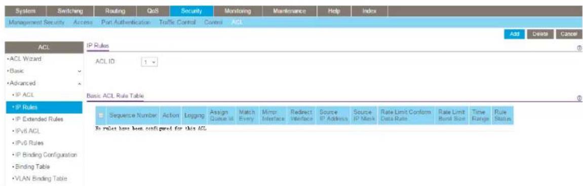
If no rules exist, the Basic ACL Rule Table shows the message No rules have been congured for this ACL. If one or more rule exists for the ACL, the rules display in the Basic ACL Rule Table.
- From the ACL ID menu, select the IP ACL for which you want to add or a change rule.
For basic IP ACLs, this must be an ID in the range from 1 to 99.
7. Click the Add button.
Standard ACL Rule Configuration(1-99)
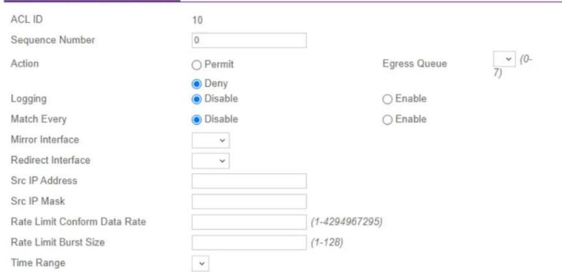
8. Specify the following match criteria for the rule:
- Sequence Number: Enter an ACL sequence number in the range from 1 to 2147483647 that is used to identify the rule. An IP ACL can contain up to 50 ru
• Action: Select the ACL forwarding action, which is one of the following:
- Permit: Forward packets that meet the ACL criteria. Egress Queue: If the selection form the Action menu is Permit, you can specify the hardware egress queue identifier that is used to handle all packets matching this IP ACL rule. The range of queue IDs is from 0 to 7.
- Deny: Drop packets that meet the ACL criteria. Logging: If the selection from the Action menu is Deny, you can enable logging for the ACL by selecting the Enable radio button. (Logging is subject to resource availability on the switch.)
- Match Every: Select one of the radio buttons to specify whether all packets must match the selected IP ACL rule:
- Enable: All packets must match the selected IP ACL rule and are either permitted or denied.
- Disable: Not all packets need to match the selected IP ACL rule.
- Mirror Interface: From the menu, select the egress interface to which the matching traffic stream must be copied, in addition to being forwarded normally by the switch.
You can either select a mirror interface or a redirect interface. These options are mutually exclusive.
- Redirect Interface: From the menu, select the egress interface to which the matching traffic stream must be redirected, bypassing any forwarding decision normally performed by the switch.
You can either select a redirect interface or a mirror interface. These options are mutually exclusive.
- Src IP Address: Specify an IP address using dotted-decimal notation to be compared to a packet's source IP address as a match criterion for the selected IP ACL rule.
- Src IP Mask: Specify the IP mask in dotted-decimal notation to be used with the source IP address.
- Rate Limit Conform Data Rate: Specify the value of the conforming data rate, which is the data rate at which conrming trafc is limited. The range is from 1 to 4294967295 Kbps.
- Rate Limit Burst Size: Specify the value of the burst size, which is the size at wl bursts of trafc above the conrming data rate are permitted. The range is from 1 to 128 Kbps.
- Time Range: From the Time Range menu, select the timer schedule that must be associated with the rule. For more information about timer schedules, see Timer schedules on page 145. If you did not set up any timer schedules, the me does not present any options.
- Click the Apply button.
Your settings are saved.
The Rule Status eld in the table shows if the rule is active or inactive. Blank means that no timer schedule is associated with the rule.
- To save the settings to the running conguration, click the Save icon.
Modify the match criteria for a basic IPv4 ACL rule To modify the match criteria for a basic IPv4 ACL rule:
-
Launch a web browser.
-
In the address eld of your web browser, enter the IP address of the switch.
The login page displays.
- Click the Main UI Login button.
The main UI login page displays in a new tab.
- Enter admin as the user name, enter your local device password, and click the Login button.
AV Line of Fully Managed Switches M4250 Series Main User Manual
The rst time that you log in, no password is required. However, you then must specify a local device password to use each subsequent time that you log in. The System Information page displays.
- Select Security > ACL > Advanced > IP Rules.
The IP Rules page displays. - From the ACL ID menu, select the ACL that includes the rule that you want to move
- In the Basic ACL Rule Table, click the rule.
The rule is a hyperlink. The Standard ACL Rule Conguration page displays. - Modify the basic IP ACL rule criteria.
- Click the Apply button. Your settings are saved.
- To save the settings to the running conguration, click the Save icon.
Delete a basic IPv4 ACL rule To delete a basic IPv4 ACL rule:
-
Launch a web browser.
-
In the address eld of your web browser, enter the IP address of the switch. The login page displays.
-
Click the Main UI Login button. The main UI login page displays in a new tab.
-
Enter admin as the user name, enter your local device password, and click the Login button. The rst time that you log in, no password is required. However, you then must specify a local device password to use each subsequent time that you log in. The System Information page displays.
-
Select Security > ACL > Advanced > IP Rules. The IP Rules page displays.
-
From the ACL ID menu, select the ACL that includes the rule that you want to move
- In the Basic ACL Rule Table, select the check box that is associated with the rule.
-
Click the Delete button. The rule is removed.
-
To save the settings to the running conguration, click the Save icon.
Congure rules for an extended IPv4 ACL
You can denote rules for extended IPv4 ACLs. The access list denition includes rules that specify whether traffic matching the criteria is forwarded normally or discarded.
Note: An implicit deny all rule is included at the end of an ACL list. This means that an ACL is applied to a packet and if none of the explicit rules match, then the final in deny all rule applies and the packet is dropped.
Add a rule for an extended IPv4 ACL To add a rule for an extended IPv4 A0
- Launch a web browser.
-
In the address eld of your web browser, enter the IP address of the switch. The login page displays.
-
Click the Main UI Login button.
The main UI login page displays in a new tab.
- Enter admin as the user name, enter your local device password, and click the Login button.
The rst time that you log in, no password is required. However, you then must specify a local device password to use each subsequent time that you log in.
The System Information page displays.
- Select Security > ACL > Advanced > IP Extended Rules.

If no rules exist, the Extended ACL Rule Table shows the message No rules have been congured for this ACL. If one or more rule exists for the ACL, the rules dis in the Extended ACL Rule Table.
- From the ACL ID/Name menu, select the IP ACL for which you want to add a rule. For extended IP ACLs, this must be an ID in the range from 101 to 199 or a nam
7. Click the Add button.

8. Congure the following options for the rule:
- Sequence Number: Enter a number in the range from 1 to 2147483647 that is used to identify the rule. An extended IP ACL can contain up to 1023 rules.
• Action: Select the ACL forwarding action, which is one of the following:
- Permit: Forward packets that meet the ACL criteria.
Egress Queue: If the selection from the Action menu is Permit, select the hardware egress queue identifier that is used to handle all packets matching this IP ACL rule. The range of queue IDs is 0 to 7.
- Deny: Drop packets that meet the ACL criteria.
This option is available if the selection from the Action menu is Deny.
If you select Enable, logging is enabled for this ACL rule (subject to resource availability on the switch).
If the access list trap ag is also enabled, periodic traps are generated, indicating the number of times the rule was evoked during the report interval, which is xed at ve minutes.
- Interface: For a Permit action, use either a mirror interface or a redirect interface:
- Select the Mirror radio button and use the menu to specify the egress interface to which the matching traffic stream is copied, in addition to being forwarded normally by the device.
- Select the Redirect radio button and use the menu to specify the egress interface to which the matching traffic stream is forced, bypassing any forwarding decision normally performed by the device.
- Match Every: Select one of the radio buttons to specify whether all packets must match the selected IP ACL rule:
- False: Not all packets need to match the selected IP ACL rule. You can congregate other match criteria on the page.
- True: All packets must match the selected IP ACL rule and are either permitted or denied. In this case, you cannot congregate other match criteria on the page.
- Protocol Type: From the menu, select a protocol that a packet's IP protocol must be matched against: IP, ICMP, IGMP, TCP, UDP, EIGRP, GRE, IPINIP, OSPF, PIM, or Other. If you select Other, enter a protocol number from 0 to 255.
- TCP Flag: If you select TCP from the Protocol Type menu, for each TCP ag, you can specify whether or not a packet's TCP ag must match. The TCP ag values are URG, ACK, PSH, RST, SYN, and FIN. You can set each TCP ag separately to one of the following options:
- Ignore: The packet's TCP ag is ignored. This is the default setting.
- Set: A packet matches this ACL rule if the TCP ag in this packet is set.
- Clear: A packet matches this ACL rule if the TCP ag in this packet is not set.
Note: If the RST and ACK ags are set, the option Established is available, indicating that a match occurs if either the RST- or ACK-specified bits are set in the packet's header.
- Src: In the Src eld, enter a source IP address, using dotted-decimal notation, to be compared to a packet's source IP address as a match criterion for the selected IP ACL rule:
- If you select the IP Address radio button, enter an IP address or an IP address range. You can enter a relevant wildcard mask to apply this criteria. If this eld is left empty, it means any.
- If you select the Host radio button, the wildcard mask is congured as 0.0.0.0. If this eld is left empty, it means any.
The wildcard mask determines which bits are used and which bits are ignored. A wildcard mask of 0.0.0.0 indicates that none of the bits are important. A wildcard of 255.255.255.255 indicates that all of the bits are important.
- Src L4: The options are available only if the selection from the Protocol Type menu is TCP or UDP. Use the source L4 port option to specify relevant matching conditions for L4 port numbers in the extended ACL rule.
You can select either the Port radio button or the Range radio button:
- Port: If you select the Port radio button, you can either enter the port number yourself or select one of the following protocols from the menu:
- The source IP TCP port protocols are Domain, Echo, FTP, FTP data, www-http, SMTP, Telnet, POP2, POP3, and BGP.
- The source IP UDP port protocols are Domain, Echo, SNMP, NTP, RIP, Time, Who, and TFTP.
Each of these values translates into its equivalent port number, which is used as both the start and end of the port range.
Select Other from the menu to enter a port number. If you select Other from the menu but leave the eld blank, it means any.
The relevant matching conditions for L4 port numbers are as follows:
- Equal: The IP ACL rule matches if the Layer 4 source port number is equal to the specified port number or port key.
- Not Equal: The IP ACL rule matches if the Layer 4 source port number is not equal to the specified port number or port key.
- Less Than: The IP ACL rule matches if the Layer 4 source port number is a lower number than the specied port number or port key.
- Greater Than: The IP ACL rule matches if the Layer 4 source port number is a higher number than the specied port number or port key.
- Range: If you select the Range radio button, the IP ACL rule matches only if the Layer 4 source port number is within the specied port range. The starting port, ending port, and all ports in between are a part of the Layer 4 port ran The Start Port and End Port elds identify the rst and last ports that are part of the port range. The values can range from 0 to 65535.
You can either enter the port range yourself or select one of the following protocols from the menu:
- The source IP TCP port protocols are Domain, Echo, FTP, FTP data, www-http, SMTP, Telnet, POP2, POP3, and BGP.
- The source IP UDP port protocols are Domain, Echo, SNMP, NTP, RIP, Time, Who, and TFTP.
Each of these values translates into its equivalent port number, which is used as both the start and end of the port range. Select Other from the menu to enter a port number. If you select Other from the menu but leave the eld blank, it means any.
The wildcard mask determines which bits are used and which bits are ignored. A wildcard mask of 0.0.0.0 indicates that none of the bits are important. A wildcard of 255.255.255.255 indicates that all of the bits are important.
- Dst: In the Dst field, enter a destination IP address, using dotted-decimal notation, to be compared to a packet's destination IP address as a match criteria for the selected IP ACL rule:
- If you select the IP Address radio button, enter an IP address with a relevant wildcard mask to apply this criteria. If this eld is left empty, it means any.
- If you select the Host radio button, the wildcard mask is congured as 0.0.0.0. If this eld is left empty, it means any.
The wildcard mask determines which bits are used and which bits are ignored. A wildcard mask of 0.0.0.0 indicates that none of the bits are important. A wildcard of 255.255.255.255 indicates that all of the bits are important.
- Dst L4: The options are available only if the selection from the Protocol Type menu is TCP or UDP. Use the destination L4 port option to specify relevant matching conditions for L4 port numbers in the extended ACL rule.
You can select either the Port radio button or the Range radio button:
- Port: If you select the Port radio button, you can either enter the port number yourself or select one of the following protocols from the menu.
- The destination IP TCP port protocols are Domain, Echo, FTP, FTP data, www-http, SMTP, Telnet, POP2, POP3, and BGP.
- The destination IP UDP port protocols are Domain, Echo, SNMP, NTP, RIP, Time, Who, and TFTP.
Each of these values translates into its equivalent port number, which is used as both the start and end of the port range.
Select Other from the menu to enter a port number. If you select Other from the menu but leave the eld blank, it means any.
The relevant matching conditions for L4 port numbers are as follows:
- Equal: The IP ACL rule matches if the Layer 4 source port number is equal to the specied port number or port key.
- Not Equal: The IP ACL rule matches if the Layer 4 source port number is not equal to the specified port number or port key.
- Less Than: The IP ACL rule matches if the Layer 4 source port number is a lower number than the specied port number or port key.
- Greater Than: The IP ACL rule matches if the Layer 4 source port number is a higher number than the specied port number or port key.
- Range: If you select the Range radio button, the IP ACL rule matches only if the Layer 4 destination port number is within the specied port range. The starting port, ending port, and all ports in between are a part of the Layer 4 port range.
The Start Port and End Port elds identify the rst and last ports that are part of the port range. They values can range from 0 to 65535.
You can either select the enter the port range yourself or select one of the following protocols from the menu:
- The destination IP TCP port protocols are Domain, Echo, FTP, FTP data, www-http, SMTP, Telnet, POP2, POP3, and BGP.
- The destination IP UDP port protocols are Domain, Echo, SNMP, NTP, RIP, Time, Who, and TFTP.
Each of these values translates into its equivalent port number, which is used as both the start and end of the port range.
Select Other from the menu to enter a port number. If you select Other from the menu but leave the eld blank, it means any.
The wildcard mask determines which bits are used and which bits are ignored. A wildcard mask of 0.0.0.0 indicates that none of the bits are important. A wildcard of 255.255.255.255 indicates that all of the bits are important.
- IGMP Type: If your selection from the Protocol Type menu is IGMP and you specify the IGMP type, the IP ACL rule matches the specied IGMP message type. The range is from 0 to 255. If this eld is left empty, it means any.
- ICMP: If your selection from the Protocol Type menu is ICMP, you can select either the Type or Message radio button:
- If you select the Type radio button, note the following:
- The Type and Code elds are enabled only if the protocol is ICMP. Use these elds to specify a match condition for ICMP packets:
- If you specify information in the Type eld, the IP ACL rule matches the specied ICMP message type. The type number can be from 0 to 255.
- If you specify information in the Code eld, the IP ACL rule matches the specied ICMP message code. The code can be from 0 to 255.
- If these elds are left empty, it means any.
- If you select the Message radio button, from the menu, select the type of the ICMP message to match with the selected IP ACL rule. Specifying a type of message implies that both the ICMP type and ICMP code are specied. The ICMP message is decoded into the corresponding ICMP type and ICMP code within the ICMP type.
The IPv4 ICMP message types are Echo, echo-reply, host-redirect, mobile-redirect, net-redirect, net-unreachable, redirect, packet-too-big, port-unreachable, source-quench, router-solicitation, router-advertisement, TTL-exceeded, time-exceeded, and unreachable.
- Fragments: Either select the Enable radio button to allow initial fragments (that is, the fragment bit is asserted) or leave the default Disable radio button selected to prevent initial fragments from being used.
This option is not valid for rules that match L4 information such as a TCP port number, because that information is carried in the initial packet.
- Service Type: Select a service type match condition for the extended IP ACL rule. The possible values are IP DSCP, IP precedence, and IP TOS, which are alternative methods to specify a match criterion for the same service type eld in the IP header. Each method uses a different user notation. After you make a selection is made, you can specify the appropriate values.
- IP DSCP: This is an optional conguration. Specify the IP DiffServ Code Point (DSCP) eld. The DSCP is dened as the high-order 6 bits of the service type octet in the IP header. Enter an integer from 0 to 63. To select the IP DSCP, select one of the DSCP keywords from the menu. To specify a numeric value, select Other and a eld displays in which you can enter numeric value of the DSCP.
- IP Precedence: This is an optional conguration. The IP precedence eld in a packet is dened as the high-order three bits of the service type octet in the IP header. Enter an integer from 0 to 7.
- IP TOS: This is an optional conguration. The IP ToS eld in a packet is dened as all 8 bits of the service type octet in the IP header. The ToS bits value is hexadecimal number from 00 to 09 and to aa to ff. The ToS mask value is a hexadecimal number from 00 to FF. The ToS mask denotes the bit positions in the ToS bits value that are used for comparison against the IP ToS eld in a packet.
For example, to check for an IP ToS value for which bit 7 is set and is the n significant value, for which bit 5 is set, and for which bit 1 is cleared, use a To bits value of 0xA0 and a ToS mask of 0xFF.
- Rate Limit Conform Data Rate: Specify the value of the conforming data rate, which is the data rate at which conrming trafc is limited. The range is from 1 to 4294967295 Kbps.
- Rate Limit Burst Size: Specify the value of the burst size, which is the size at wl bursts of trafc above the conrming data rate are permitted. The range is from 1 to 128 Kbps.
- Time Range: From the Time Range menu, select the timer schedule that must be associated with the rule. For more information about timer schedules, see
AV Line of Fully Managed Switches M4250 Series Main User Manual
Timer schedules on page 145. If you did not set up any timer schedules, the me does not present any options.
- Click the Apply button.
Your settings are saved.
The Rule Status eld in the table shows if the rule is active or inactive. Blank means that no timer schedule is associated with the rule.
- To save the settings to the running conguration, click the Save icon.
Modify the match criteria for an extended IPv4 ACL rule To modify the match criteria for an existing extended IPv4 ACL rule:
- Launch a web browser.
-
In the address eld of your web browser, enter the IP address of the switch. The login page displays.
-
Click the Main UI Login button.
The main UI login page displays in a new tab.
- Enter admin as the user name, enter your local device password, and click the Login button.
The rst time that you log in, no password is required. However, you then must specify a local device password to use each subsequent time that you log in.
The System Information page displays.
- Select Security > ACL > Advanced > IP Extended Rules.
The IP Extended Rules page displays.
-
From the ACL ID/Name menu, select the ACL that includes the rule that you want to modify.
-
In the Extended ACL Rule Table, click the rule.
The rule is a hyperlink. The Extended ACL Rule Conguration page displays.
-
Modify the extended IP ACL rule criteria.
-
Click the Apply button.
Your settings are saved.
- To save the settings to the running conguration, click the Save icon.
Delete an extended IPv4 ACL rule To delete an extended IPv4 ACL rule:
-
Launch a web browser.
-
In the address eld of your web browser, enter the IP address of the switch. The login page displays.
-
Click the Main UI Login button.
The main UI login page displays in a new tab.
- Enter admin as the user name, enter your local device password, and click the Login button.
The rst time that you log in, no password is required. However, you then must specify a local device password to use each subsequent time that you log in. The System Information page displays.
- Select Security > ACL > Advanced > IP Extended Rules.
The IP Extended Rules page displays.
-
From the ACL ID/Name menu, select the ACL that includes the rule that you want to delete.
-
In the Extended ACL Rule Table, select the check box that is associated with the ru
-
Click the Delete button.
The rule is removed.
- To save the settings to the running conguration, click the Save icon.
Congure an IPv6 ACL
An IPv6 ACL consists of a set of rules that are matched sequentially against a packet. When a packet meets the match criteria of a rule, the specied rule action (Permit or Deny) is taken, and the additional rules are not checked for a match. You must specify the interfaces to which an IPv6 ACL applies, as well as whether it applies to inbound outbound trafc.
Multiple steps are involved in dening an IPv6 ACL and applying it to the switch:
-
Add an IPv6 ACL ID (see Add an IPv6 ACL on page 680). An IPv6 ACL must start with a name string that is up to 31 alphanumeric characters in length. The name must start with an alphabetic character.
-
Create an IPv6 rule (see Congure rules for an IPv6 ACL on page 682).
-
Associate the IPv6 ACL with one or more interfaces (see Congure IP ACL interface bindings on page 688).
You can display or delete IPv6 ACL congrurations in the IP ACL Binding table (see Display or delete IP ACL bindings in the IP ACL binding table on page 690).
Add an IPv6 ACL To add an IPv6 ACL:
- Launch a web browser.
- In the address eld of your web browser, enter the IP address of the switch. The login page displays.
- Click the Main UI Login button.
The main UI login page displays in a new tab.
- Enter admin as the user name, enter your local device password, and click the Login button.
The rst time that you log in, no password is required. However, you then must specify a local device password to use each subsequent time that you log in. The System Information page displays.
- Select Security > ACL > Advanced > IPv6 ACL.
The IPv6 ACL page displays.
- In the IPv6 ACL eld, specify a name to identify the IPv6 ACL.
This is the IPv6 ACL name string, which includes up to 31 alphanumeric characters only. The name must start with an alphabetic character.
- Click the Add button.
The IPv6 ACL is added to the switch conguration.
- To save the settings to the running conguration, click the Save icon.
The following table describes the noncongorable information that is displayed.
Table 163. IPv6 ACL information
| DescriptionField |
| The current number of ACLs congured on the switch.Current Number of ACL |
| The maximum number of IP ACLs that can be congured on the switch.Maximum ACI |
Table 163. IPv6 ACL information (Continued)
| DescriptionField |
| The maximum number of ACLs that can be congured on the switch.Rules |
| The type is IPv6 ACL.Type |
Change the name of an IPv6 ACL To change the name of an IPv6 ACL:
- Launch a web browser.
- In the address eld of your web browser, enter the IP address of the switch. The login page displays.
- Click the Main UI Login button. The main UI login page displays in a new tab.
-
Enter admin as the user name, enter your local device password, and click the Login button. The rst time that you log in, no password is required. However, you then must specify a local device password to use each subsequent time that you log in. The System Information page displays.
-
Select Security > ACL > Advanced > IPv6 ACL. The IPv6 ACL page displays.
-
Select the check box that is associated with the IPv6 ACL.
-
In the IPv6 ACL eld, specify the new name.
-
Click the Apply button. Your settings are saved.
-
To save the settings to the running conguration, click the Save icon.
Delete an IPv6 ACL To delete an IPv6 ACL:
- Launch a web browser.
- In the address eld of your web browser, enter the IP address of the switch. The login page displays.
- Click the Main UI Login button. The main UI login page displays in a new tab.
- Enter admin as the user name, enter your local device password, and click the Login button.
The rst time that you log in, no password is required. However, you then must specify a local device password to use each subsequent time that you log in.
The System Information page displays.
- Select Security > ACL > Advanced > IPv6 ACL.
The IPv6 ACL page displays.
-
Select the check box that is associated with the IPv6 ACL.
-
Click the Delete button.
The IPv6 ACL is removed.
- To save the settings to the running conguration, click the Save icon.
Congure rules for an IPv6 ACL
You can denote rules for IPv6 ACLs. The access list denition includes rules that specify whether traffic matching the criteria is forwarded normally or discarded.
Add a rule for an IPv6 ACL To add a rule for an ACL IPv6:
- Launch a web browser.
- In the address eld of your web browser, enter the IP address of the switch.
The login page displays.
- Click the Main UI Login button.
The main UI login page displays in a new tab.
- Enter admin as the user name, enter your local device password, and click the Login button.
The rst time that you log in, no password is required. However, you then must specify a local device password to use each subsequent time that you log in.
The System Information page displays.
- Select Security > ACL > Advanced > IPv6 Rules.

If no rules exist, the IPv6 ACL Rule Table shows the message No rules have been congured for this ACL. If one or more rule exists for the ACL, the rules display in the IPv6 ACL Rule Table.
-
From the ACL Name menu, select the IPv6 ACL for which you want to add or a change a rule.
-
Click the Add button.

- Congure the following options for the rule:
- Sequence Number: Enter a whole number in the range of 1 to 2147483647. This number is used to identify the rule. An IPv6 ACL can contain up to 1023 rules.
- Action: Select the ACL forwarding action by selecting one of the following radio buttons:
- Permit: Forward packets that meet the ACL criteria.
- Deny: Drop packets that meet the ACL criteria.
- Egress Queue: If you select the Permit radio button, select the hardware egress queue identifier that is used to handle all packets matching this IPv6 ACL rule. The range of queue IDs is 0 to 7.
- Logging: If you select the Deny radio button, you can enable logging for the ACL by selecting the Enable radio button. (Logging is subject to resource availability in the device.) If the access list trap ag is also enabled, periodic traps are generated, indicating the number of times this rule was evoked during the report interval. A xed ve-minute report interval is used for the switch. A trap is not issued if the ACL rule hit count is zero for the current interval.
- Interface: If you select the Permit radio button, use either a mirror interface or a redirect interface:
- Select the Mirror Interface radio button and use the menu to specify the egress interface to which the matching traffic stream is copied, in addition to being forwarded normally by the device.
- Select the Redirect Interface radio button and use the menu to specify the egress interface to which the matching traffic stream is forced, bypassing any forwarding decision normally performed by the device.
- Match Every: Select whether all packet must match the selected IPv6 ACL rule:
- False: Not all packets need to match the selected IPv6 ACL rule. You can congregate other match criteria on the page.
- True: All packets must match the selected IPv6 ACL rule and are either permitted or denied. In this case, you cannot congregate other match criteria on the page.
- Protocol Type: Specify the IPv6 protocol type in one of the following ways:
• From the Protocol Type menu, select IPv6, ICMPv6, TCP, or UDP.
- From the Protocol Type menu, select Other, and in the associated field, specify an integer ranging from 0 to 255. This number represents the IPv6 protocol.
- TCP Flag: If you select TCP from the Protocol Type menu, for each TCP ag, you can specify whether or not a packet's TCP ag must match. The TCP ag values are URG, ACK, PSH, RST, SYN, and FIN. You can set each TCP ag separately to one of the following options:
- Ignore: The packet's TCP ag is ignored. This is the default setting.
- Set: A packet matches this ACL rule if the TCP ag in this packet is set.
- Clear: A packet matches this ACL rule if the TCP ag in this packet is not set.
Note: If the RST and ACK ags are set, the option Established is available,
indicating that a match occurs if either the RST- or ACK-specified bits are set in the packet's header.
- Src: In the Src eld, enter a source IPv6 address or source IPv6 address range to be compared to a packet's source IPv6 address as a match criterion for the select IPv6 ACL rule:
- If you select the IPv6 Address radio button, enter an IPv6 address or IPv6 range to apply this criteria. If this eld is left empty, it means any.
- If you select the Host radio button, enter a host source IPv6 address to match the specied IPv6 address. If this eld is left empty, it means any.
The source IPv6 address argument must be in the form documented in RFC 2373 where the address is specified in hexadecimal numbers using 16-bit values between colons.
- Src L4: The options are available only if the selection from the Protocol Type menu is TCP or UDP. Use the source L4 port option to specify relevant matching conditions for L4 port numbers in the IPv6 ACL rule.
You can either enter the port number yourself or select one of the following protocols from the menu:
- The source IP TCP port protocols are Domain, Echo, FTP, FTP data, www-http, SMTP, Telnet, POP2, POP3, and BGP.
- The source IP UDP port protocols are Domain, Echo, SNMP, NTP, RIP, Time, Who, and TFTP.
Each of these values translates into its equivalent port number, which is used as both the start and end of the port range.
Select Other from the menu to enter a port number. If you select Other from the menu but leave the eld blank, it means any.
The only relevant matching condition for L4 port numbers is equal. This means that an IPv6 ACL rule matches only if the Layer 4 source port number is equal to the specified port number or port protocol.
- Dst: In the Dst field, enter a destination IPv6 address to be compared to a packet's destination IPv6 address as a match criterion for the selected IPv6 ACL rule:
- If you select the IPv6 Address radio button, enter an IPv6 address to apply this criteria. If this eld is left empty, it means any.
- If you select the Host radio button, enter a host source IPv6 address to match the specied IPv6 address. If this eld is left empty, it means any.
The source IPv6 address argument must be in the form documented in RFC 2373 where the address is specified in hexadecimal numbers using 16-bit values between colons.
- Dst L4: The options are available only if the selection from the Protocol Type menu is TCP or UDP. Use the destination L4 port option to specify relevant matching conditions for L4 port numbers in the IPv6 ACL rule.
You can either enter the port number yourself or select one of the following protocols from the menu:
- The destination IP TCP port protocols are Domain, Echo, FTP, FTP data, www-http, SMTP, Telnet, POP2, POP3, and BGP.
- The destination IP UDP port protocols are Domain, Echo, SNMP, NTP, RIP, Time, Who, and TFTP.
Each of these values translates into its equivalent port number, which is used as both the start and end of the port range.
Select Other from the menu to enter a port number. If you select Other from the menu but leave the eld blank, it means any.
The only relevant matching condition for L4 port numbers is equal. This means that an IPv6 ACL rule matches only if the Layer 4 destination port number is equal to the specified port number or port protocol.
- ICMPv6: The Type and Message fields are enabled only if the protocol is ICMPv6.
Use these elds to specify a match condition for ICMPv6 packets. Select either the Type or Message radio button:
- If you select the Type radio button, note the following:
- The Type and Code elds are enabled only if the protocol is ICMPv6. Use these elds to specify a match condition for ICMPv6 packets:
- If you specify information in the Type eld, the IPv6 ACL rule matches the specied ICMPv6 message type. The type number can be from 0 to 255.
- If you specify information in the Code eld, the IPv6 ACL rule matches the specied ICMPv6 message code. The code can be from 0 to 255.
- If these elds are left empty, it means any.
- If you select the Message radio button, note the following:
- Select the type of the ICMPv6 message to match with the selected IPv6 ACL rule. Specifying a type of message implies that both the ICMPv6 type and ICMPv6 code are specied. The ICMPv6 message is decoded into the corresponding ICMPv6 type and ICMPv6 code within the ICMP type.
- The ISMPv6 message types are destination-unreachable, echo-reply, echo-request, header, hop-limit, MLD-query, MLD-reduction, MLD-report, next-header, no-admin, no-route, packet-too-big, port-unreachable, router-solicitation, router-advertisement, router-renumbering, unreachable, time-exceeded, nd-na, and nd-ns.
- Fragments: Either select the Enable radio button to allow initial fragments (that is, the fragment bit is asserted) or leave the default Disable radio button selected to prevent initial fragments from being used.
This option is not valid for rules that match L4 information such as TCP port number because that information is carried in the initial packet.
- Flow Label: The Flow Label field is enabled only if the selection from the Protocol
Type menu is ICMPv6. The ow label is 20-bit number that is unique to an IPv6 packet and that is used by end stations to signify quality-of-service handling in routers. The range for the ow label is from 0 to 1048575.
- IPv6 DSCP Service: Specify the IP DiffServ Code Point (DSCP) eld. This is an optional conguration.
The DSCP is dened as the high-order six bits of the service type octet in the IPv header. Enter an integer from 0 to 63. To select the IPv6 DSCP, select one of the DSCP keywords. To specify a numeric value, select Other and enter the numeric value of the DSCP. - Rate Limit Conform Data Rate: Specify the value of the conforming data rate, which is the data rate at which conrming trafc is limited. The range is from 1 to 4294967295 Kbps.
- Rate Limit Burst Size: Specify the value of the burst size, which is the size at wl bursts of trafc above the conming data rate are permitted. The range is from 1 to 128 Kbps.
-
Time Range: From the Time Range menu, select the timer schedule that must be associated with the rule. For more information about timer schedules, see Timer schedules on page 145. If you did not set up any timer schedules, the me does not present any options.
-
Click the Apply button.
Your settings are saved.
The Rule Status eld in the table shows if the rule is active or inactive. Blank means that no timer schedule is associated with the rule.
- To save the settings to the running conguration, click the Save icon.
Modify the match criteria for an IPv6 ACL rule To modify the match criteria for an IPv6 ACL rule:
- Launch a web browser.
-
In the address eld of your web browser, enter the IP address of the switch.
The login page displays. -
Click the Main UI Login button.
The main UI login page displays in a new tab.
- Enter admin as the user name, enter your local device password, and click the Login button.
The rst time that you log in, no password is required. However, you then must specify a local device password to use each subsequent time that you log in.
The System Information page displays.
- Select Security > ACL > Advanced > IPv6 Rules.
The IPv6 Rules page displays.
- From the ACL Name menu, select the ACL that includes the rule that you want to modify.
- In the IPv6 ACL Rule Table, click the rule.
The rule is a hyperlink. The IPv6 ACL Rule Conguration page displays.
- Modify the IPv6 ACL rule criteria.
- Click the Apply button.
Your settings are saved.
- To save the settings to the running conguration, click the Save icon.
Delete an IPv6 ACL rule To delete an IPv6 ACL rule:
- Launch a web browser.
- In the address eld of your web browser, enter the IP address of the switch. The login page displays.
- Click the Main UI Login button.
The main UI login page displays in a new tab.
- Enter admin as the user name, enter your local device password, and click the Login button.
The rst time that you log in, no password is required. However, you then must specify a local device password to use each subsequent time that you log in.
The System Information page displays.
- Select Security > ACL > Advanced > IPv6 Rules.
The IPv6 Rules page displays.
- From the ACL Name menu, select the ACL that includes the rule that you want to delete.
- In the IPv6 ACL Rule Table, select the check box that is associated with the rule.
- Click the Delete button.
The rule is removed.
- To save the settings to the running conguration, click the Save icon.
Congure IP ACL interface bindings
When you bind a basic IPv4, extended IPv4, or IPv6 ACL to an interface, all the rules that you dened for the IP ACL are applied to the selected interface.
If resources on the switch are insufficient, an attempt to bind an ACL to an interface fa
To bind an IP ACL to one or more interfaces:
-
Launch a web browser.
-
In the address eld of your web browser, enter the IP address of the switch. The login page displays.
-
Click the Main UI Login button.
The main UI login page displays in a new tab.
- Enter admin as the user name, enter your local device password, and click the Login button.
The rst time that you log in, no password is required. However, you then must specify a local device password to use each subsequent time that you log in. The System Information page displays.
- Select Security > ACL > Advanced > IP Binding Conguration.

The previous figure shows the page for a 12-port model and includes some examples
- From the ACL ID menu, select an IP ACL.
Note: Binding an ACL to an interface fails is the switch has no resources to bind a new ACL. In addition, you cannot bind both an IPv4 ACL and an IPv6 ACL to an interface.
- From the Direction menu, select the packet ltering direction for the ACL:
- Inbound: The rule is applied to trafc entering the port.
- Outbound: The rule is applied to trafc leaving the port.
- In the Sequence Number eld, optionally specify a number to indicate the order of the access list relative to other access lists already assigned to the interface and direction.
A low number indicates high precedence order. If a sequence number is already in use for the interface and direction, the specied access list replaces the currently attached access list using that sequence number. If you do not specify the sequence number (meaning that the value is 0), a sequence number that is one number greater than the highest sequence number currently in use for the interface and direction is used. The range is from 1 to 4294967295.
- To add the selected ACL to a port or LAG, in the Ports table or LAG table, click the port or LAG so that a check mark displays.
You can add the ACL to several ports and LAGs.
The Ports and LAG tables display the available interfaces for ACL bindings.
- Click the Apply button.
Your settings are saved.
- To save the settings to the running conguration, click the Save icon.
The following table describes the noncongorable information displayed.
Table 164. Interface Binding Status information
| DescriptionField | |
| The selected interface.Interface | |
| The selected packet ltering direction for the ACL.Direction | |
| The type of ACL assigned to the selected interface and direction.ACL Type | |
| ACL ID/Name | The ACL number or name identifying the ACL assigned to the selected interface and direction. |
| Sequence Number | The sequence number signifying the order of specied ACL relative to other ACLs assigned to the selected interface and direction. |
Display or delete IP ACL bindings in the IP ACL bir table
You can display or delete bindings for basic IPv4, extended IPv4, and IPv6 ACLs.
To display or delete IP ACL bindings:
- Launch a web browser.
-
In the address eld of your web browser, enter the IP address of the switch. The login page displays.
-
Click the Main UI Login button. The main UI login page displays in a new tab.
-
Enter admin as the user name, enter your local device password, and click the Login button. The rst time that you log in, no password is required. However, you then must specify a local device password to use each subsequent time that you log in. The System Information page displays.
-
Select Security > ACL > Advanced > Binding Table. The Binding Table page displays. This table displays the IP ACL-to-interface bindings.
-
To delete an IP ACL-to-interface binding, do the following: a. Select the check box next to the interface. b. Click the Delete button. The binding is removed.
-
To save the settings to the running conguration, click the Save icon. The following table describes the noncongorable information displayed.
Table 165. Interface Binding Status information
| DescriptionField |
| The selected interface.Interface |
| The selected packetitering direction for the ACL.Direction |
| The type of ACL assigned to the selected interface and direction.ACL Type |
Table 165. Interface Binding Status information (Continued)
| DescriptionField | |
| ACL ID/Name | The ACL number or name identifying the ACL assigned to the selected interface and direction. |
| Sequence Number | The sequence number signifying the order of specied ACL relative to other ACLs assigned to the selected interface and direction. |
Congure VLAN ACL bindings
You can associate a MAC ACL, any type of IPv4 ACL, or an IPv6 ACL with a VLAN. V you do so, the ACL is applied to all interfaces that are members of the VLAN.
Add a VLAN ACL binding To add a VLAN ACL binding:
-
Launch a web browser.
-
In the address eld of your web browser, enter the IP address of the switch. The login page displays.
-
Click the Main UI Login button. The main UI login page displays in a new tab.
-
Enter admin as the user name, enter your local device password, and click the Login button. The rst time that you log in, no password is required. However, you then must specify a local device password to use each subsequent time that you log in. The System Information page displays.
-
Select Security > ACL> Advanced > VLAN Binding Table. The VLAN Binding Table page displays.
-
In the VLAN ID eld, enter the VLAN ID to which the binding must apply.
-
From the Direction menu, select the packet ltering direction for the ACL:
-
Inbound: The rule is applied to trafc entering the port.
-
Outbound: The rule is applied to trafc leaving the port.
-
In the Sequence Number eld, optionally specify a number to indicate the order of the access list relative to other access lists already assigned to the VLAN and direction. A low number indicates high precedence order. If a sequence number is already in use for the VLAN ID and direction, the specied access list replaces the currently attached access list using that sequence number. If you do not specify the sequence number (meaning that the value is 0), a sequence number that is one number greater
AV Line of Fully Managed Switches M4250 Series Main User Manual
than the highest sequence number currently in use for the VLAN ID and direction is used. The range is from 1 to 4294967295.
- From the ACL Type menu, select the type of ACL.
You can select a MAC ACL, IP ACL, or IPv6 ACL.
-
From the ACL ID list, select the ID or name of the ACL that must be bound to the specified VLAN.
-
Click the Add button.
The VLAN ACL binding is added.
- To save the settings to the running conguration, click the Save icon.
Remove a VLAN ACL binding To remove a VLAN ACL binding:
-
Launch a web browser.
-
In the address eld of your web browser, enter the IP address of the switch. The login page displays.
-
Click the Main UI Login button.
The main UI login page displays in a new tab.
- Enter admin as the user name, enter your local device password, and click the Login button.
The rst time that you log in, no password is required. However, you then must specify a local device password to use each subsequent time that you log in.
The System Information page displays.
- Select Security > ACL > Advanced > VLAN Binding Table.
The VLAN Binding Table page displays.
-
Select the check box for the VLAN binding that you want to remove.
-
Click the Delete button.
The VLAN ACL binding is removed.
- To save the settings to the running conguration, click the Save icon.
8
Monitor the Switch and Network
This chapter covers the following topics:
• Port and EAP packet statistics
- Perform a cable test
- Logs
- Syslog and log server host settings
- Trap log
- Event log
- Port mirroring
- RSPAN VLANs and source and destination switches
- sFlow monitoring
• Display license information
Port and EAP packet statistics
You can view port statistics, including detailed statistics, and Extensible Authentication Protocol (EAP) packets statistics.
Display or clear port statistics
You can display a summary of per-port traffic statistics on the switch and clear the statistics.
To view or clear port statistics:
- Launch a web browser.
-
In the address eld of your web browser, enter the IP address of the switch. The login page displays.
-
Click the Main UI Login button. The main UI login page displays in a new tab.
-
Enter admin as the user name, enter your local device password, and click the Login button. The rst time that you log in, no password is required. However, you then must specify a local device password to use each subsequent time that you log in. The System Information page displays.
-
Select Monitoring > Ports > Port Statistics. The Port Statistics page displays.
-
Select whether to display physical interfaces, LAGs, or both by clicking one of the following links above the table heading:
• 1: Only physical interfaces are displayed. This is the default setting.
- LAG: Only LAGs are displayed.
- All: Both physical interfaces and LAGs are displayed.
-
To nd a single interface, select the check box associated with the port, or type the port number in the Go To Interface eld and click the Go button.
-
To clear counters, do one of the following:
-
To clear all the counters for all ports on the switch, select the check box in the heading and click the Clear button.
-
To clear the counters for a specific port, select the check box for the port and click the Clear button.
-
To refresh the page, click the Refresh button.
-
To save the settings to the running conguration, click the Save icon.
The following table describes the per-port statistics displayed on the page.
Table 166. Port statistics information
| DescriptionField | |
| The interface.Interface | |
| Errors | The total number of packets that were received without errors. Total Packets Received |
| Packets Received With Error | The number of inbound packets that contained errors, preventing them from being delivered to a higher-layer protocol. |
| Broadcast Packets Received | The number of good packets received that were directed to the broadcast address. This does not include multicast packets. |
| The number of frames that were transmitted by this port to its segment. Packets Tr | |
| Transmit Packet Errors | The number of outbound packets that could not be transmitted because of errors. |
| Collision Frames | The best estimate of the total number of collisions on this Ethernet segment. |
| The total number of link down events on the port. Number of Link Down Events | |
| Link Flaps | The number of occurrences of link-down-to-link up events (that is, one link ap) during the debouncing time. |
| The received data rate in Mbps. Received Rate (Mbps) | |
| The transmitted data rate in Mbps. Transmitted Rate (Mbps) | |
| The received data rate with errors in Mbps. Received Error Rate | |
| The transmitted data rate with errors in Mbps. Transmitted Error Rate | |
| The number of received packets per second. Packets Received Per Second | |
| Packets Transmitted Per Second | the number of transmitted packets per second. |
| Time Since Counters Last Cleared | The elapsed time in days, hours, minutes, and seconds since the statistics for this port were last cleared. |
Display or clear detailed statistics for a port
For a specific port, you can display a variety of per-port traffic statistics or clear the statistics.
To display and clear detailed statistics for a port:
- Launch a web browser.
-
In the address eld of your web browser, enter the IP address of the switch. The login page displays.
-
Click the Main UI Login button. The main UI login page displays in a new tab.
-
Enter admin as the user name, enter your local device password, and click the Login button. The rst time that you log in, no password is required. However, you then must specify a local device password to use each subsequent time that you log in. The System Information page displays.
-
Select Monitoring > Ports > Port Detailed Statistics. The Port Detailed Statistics page displays.
-
From the Interface menu, select the interface (a physical port or LAG) for which you want to display the statistics.
-
From the MST ID menu, select the MST ID associated with the interface (if available)
-
To refresh the page, click the Refresh button.
-
To clear all the counters, click the Clear button. All statistics for the port are reset to the default values.
-
To save the settings to the running conguration, click the Save icon. The following table describes the detailed port statistics displayed on the page.
Table 167. Port detailed statistics information
| DescriptionField | |
| The ifIndex of the interface table entry associated with the port.ifIndex | |
| Port Type | The port is either Normal or one of the following:Mirrored: This port is a mirrored port in a port mirroring conguration.Probe: This port is the probe port in a port mirroring conguration.Port Channel: The port is a member of a LAG. |
| Port Channel ID | If the port is a member of a port channel, the port channel's interface ID and name display. Otherwise, Disable displays. |
| Port Role | Each MST bridge port that is enabled is assigned a port role for each spanning tree. The port role is one of the following values: Root, Designated, Alternate, Backup, Master, or Disabled. |
| STP Mode | The Spanning Tree Protocol administrative mode that is associated with the port or port channel. The options are as follows:Enable:Spanning tree is enabled for the port.Disable:Spanning tree is disabled for the port. |
| STP State | The port's current Spanning Tree state. This state controls what action a port takes on receipt of a frame. If the bridge detects a malfunctioning port it places that port into the broken state. The states are denied in IEEE 802.1D:DisabledBlockingListeningLearningForwardingBroken |
| Admin Mode | The port control administration state. The port must be enabled for it to be allowed into the network. The default is enabled. |
| Flow Control Mode | Indicates whether ow control is enabled or disabled for the port. This elddoes not apply to LAGs. |
| LACP Mode | Indicates the Link Aggregation Control Protocol administrative state. The modemust be enabled for the port to participate in link aggregation. |
| Physical Mode | Indicates the port speed and duplex mode. In autonegotiation mode theduplex mode and speed are set by the autonegotiation process. |
| Indicates the port speed and duplex mode.Physical Status | |
| Indicates whether the link is up or down.Link Status | |
| Indicates whether or not the port sends a trap when link status changes.Link Trap | |
| Packets RX and TX 64 Oct | The total number of packets (including bad packets) received or transmittedthat were 64 octets in length (excluding framing bits but including FCS octets). |
| Packets RX and TX 65-127 Octets | The total number of packets (including bad packets) received or transmittedthat were between 65 and 127 octets in length inclusive (excluding framingbits but including FCS octets). |
| Packets RX and TX 128-255 Octets | The total number of packets (including bad packets) received or transmittedthat were between 128 and 255 octets in length inclusive (excluding framingbits but including FCS octets). |
| DescriptionField | |
| Packets RX and TX 256-51 Octets | The total number of packets (including bad packets) received or transmitted that were between 256 and 511 octets in length inclusive (excluding framing bits but including FCS octets). |
| Packets RX and TX 512-102 Octets | The total number of packets (including bad packets) received or transmitted that were between 512 and 1023 octets in length inclusive (excluding framing bits but including FCS octets). |
| Packets RX and TX 1024-1518 Octets | The total number of packets (including bad packets) received or transmitted that were between 1024 and 1518 octets in length inclusive (excluding framing bits but including FCS octets). |
| Packets RX and TX 1519-2047 Octets | The total number of packets (including bad packets) received or transmitted that were between 1519 and 2047 octets in length inclusive (excluding framing bits but including FCS octets). |
| Packets RX and TX 2048-4095 Octets | The total number of packets (including bad packets) received or transmitted that were between 2048 and 4095 octets in length inclusive (excluding framing bits but including FCS octets). |
| Packets RX and TX 4096-9216 Octets | The total number of packets (including bad packets) received or transmitted that were between 4096 and 9216 octets in length inclusive (excluding framing bits but including FCS octets). |
| Octets Received | The total number of octets of data (including those in bad packets) received on the network (excluding framing bits but including FCS octets). This object can be used as a reasonable estimate of Ethernet utilization. If greater precision is desired, the etherStatsPkts and etherStatsOctets objects must be sampled before and after a common interval. |
| Packets Received 64 Octets | The total number of packets (including bad packets) received that were 64 octets in length (excluding framing bits but including FCS octets). |
| Packets Received 65-127 Octets | The total number of packets (including bad packets) received that were between 65 and 127 octets in length inclusive (excluding framing bits but including FCS octets). |
| Packets Received 128-255 Octets | The total number of packets (including bad packets) received that were between 128 and 255 octets in length inclusive (excluding framing bits but including FCS octets). |
| Packets Received 256-511 Octets | The total number of packets (including bad packets) received that were between 256 and 511 octets in length inclusive (excluding framing bits but including FCS octets). |
| Packets Received 512-1023 Octets | The total number of packets (including bad packets) received that were between 512 and 1023 octets in length inclusive (excluding framing bits but including FCS octets). |
| Packets Received 1024-1518 Octets | The total number of packets (including bad packets) received that were between 1024 and 1518 octets in length inclusive (excluding framing bits but including FCS octets).DescriptionField |
| Packets Received > 1518 Octets | The total number of packets received that were longer than 1518 octets (excluding framing bits, but including FCS octets) and were otherwise well formed. |
| Without Errors | The total number of packets received that were without errors.Total Packets Received |
| Unicast Packets Received | The number of subnetwork-unicast packets delivered to a higher-Layer protocol. |
| Multicast Packets Received | The total number of good packets received that were directed to a multicast address. This number does not include packets directed to the broadcast address. |
| Broadcast Packets Received | The total number of good packets received that were directed to the broadcast address. This does not include multicast packets. |
| Receive Packets Discarded | The number of inbound packets that were discarded even though no errors were detected to prevent their being delivered to a higher-layer protocol. A possible reason for discarding a packet could be to free up buffer space. |
| Total Packets Received with MAC Errors | The total number of inbound packets that contained errors preventing them from being deliverable to a higher-Layer protocol. |
| Jabbers Received | The total number of packets received that were longer than 1518 octets (excluding framing bits, but including FCS octets), and had either a bad frame check sequence (FCS) with an integral number of octets (FCS Error) or a bad FCS with a nonintegral number of octets (alignment error). This denition of jabber is different from the denition in IEEE-802.3 section 8.2.1.5 (10BASE5) and section 10.3.1.4 (10BASE2). These documents dene jabber as the condition where any packet exceeds 20 ms. The allowed range to detect jabber is between 20 ms and 150 ms. |
| Fragments Received | The total number of packets received that were less than 64 octets in length with ERROR CRC (excluding framing bits but including FCS octets). |
| Undersize Received | The total number of packets received that were less than 64 octets in length with GOOD CRC (excluding framing bits but including FCS octets). |
| Alignment Errors | The total number of packets received with a length (excluding framing bits, but including FCS octets) of between 64 and 1518 octets, inclusive, but had a bad frame check sequence (FCS) with a nonintegral number of octets. |
| Rx FCS Errors | The total number of packets received with a length (excluding framing bits, but including FCS octets) of between 64 and 1518 octets, inclusive, but had a bad frame check sequence (FCS) with an integral number of octets |
| Overruns | The total number of frames discarded because this port was overloaded with incoming packets, and could not keep up with the inow. |
| Total Received Packets NotA count of valid frames received that were discarded (that is, Itered) by the Forwarded | forwarding process. |
| 802.3x Pause Frames Received | A count of MAC control frames received on this interface with an opcode indicating the PAUSE operation. This counter does not increment when the interface is operating in half-duplex mode. |
| Unacceptable Frame Type | The number of frames discarded from this port due to being an unacceptable frame type. |
| Total Packets Transmitted (Octets) | The total number of octets of data (including those in bad packets) transmitted on the network (excluding framing bits but including FCS octets). This object can be used as a reasonable estimate of Ethernet utilization. If greater precision is desired, the etherStatsPkts and etherStatsOctets objects must be sampled before and after a common interval. |
| Packets Transmitted 64 Octets | The total number of packets (including bad packets) received that were 64 octets in length (excluding framing bits but including FCS octets). |
| Packets Transmitted 65-127 Octets | The total number of packets (including bad packets) received that were between 65 and 127 octets in length inclusive (excluding framing bits but including FCS octets). |
| Packets Transmitted 128-255 Octets | The total number of packets (including bad packets) received that were between 128 and 255 octets in length inclusive (excluding framing bits but including FCS octets). |
| Packets Transmitted 256-511 Octets | The total number of packets (including bad packets) received that were between 256 and 511 octets in length inclusive (excluding framing bits but including FCS octets). |
| Packets Transmitted 512-1023 Octets | The total number of packets (including bad packets) received that were between 512 and 1023 octets in length inclusive (excluding framing bits but including FCS octets). |
| Packets Transmitted 1024-1518 Octets | The total number of packets (including bad packets) received that were between 1024 and 1518 octets in length inclusive (excluding framing bits but including FCS octets). |
| Packets Transmitted > 1518 Octets | The total number of packets transmitted that were longer than 1518 octets (excluding framing bits, but including FCS octets) and were otherwise well formed. This counter has a max increment rate of 815 counts per sec at 10 Mb/s. |
| Maximum Frame Size | The maximum Ethernet frame size that the interface supports or is congured to use, including the Ethernet header, CRC, and payload. The minimum size is 1500; The maximum size is 12270; The default size is 9198. |
| Successfully | The number of frames that were transmitted by this port to its segment.Total Packets Tr |
| Unicast Packets Transmitted | The total number of packets that higher-level protocols requested be transmitted to a subnetwork-unicast address, including those that were discarded or not sent. |
| Multicast Packets Transmitted | The total number of packets that higher-level protocols requested be transmitted to a multicast address, including those that were discarded or not sent. |
| Broadcast Packets Transmitted | The total number of packets that higher-level protocols requested be transmitted to the broadcast address, including those that were discarded or not sent. |
| Transmit Packets Discarded | The total number of outbound packets that were discarded even though no errors were detected that would prevent the packets from being delivered to a higher-layer protocol.A possible reason for discarding a packet could be to free up buffer space. |
| The sum of single, multiple, and excessive collisions.Total Transmit Errors | |
| Tx FCS Errors | The total number of transmitted packets with a length (excluding framing bits but including FCS octets) between 64 and 1518 octets, inclusive, and with a bad Frame Check Sequence (FCS) with an integral number of octets. |
| Total Transmit Packets Discarded | The sum of single collision frames discarded, multiple collision frames discarded, and excessive frames discarded. |
| Single Collision Frames | The number of successfully transmitted frames on a particular interface for which transmission is inhibited by exactly one collision. |
| Multiple Collision Frames | The number of successfully transmitted frames on a particular interface for which transmission is inhibited by more than one collision. |
| Excessive Collision Frames | The number of frames for which transmission on a particular interface fails due to excessive collisions. |
| The number of STP BPDUs received at the selected port.STP BPDUs Received | |
| The number of STP BPDUs transmitted from the selected port.STP BPDUs Transmitted | |
| The number of RSTP BPDUs received at the selected port.RSTP BPDUs Received | |
| The number of RSTP BPDUs transmitted from the selected port.RSTP BPDUs Transmitted | |
| The number of MSTP BPDUs received at the selected port.MSTP BPDUs Received | |
| The number of MSTP BPDUs transmitted from the selected port.MSTP BPDUs Transmitted | |
| 802.3x Pause Frames Transmitted | The number of MAC control frames transmitted on this interface with an opcode indicating the PAUSE operation. This counter does not increment when the interface is operating in half-duplex mode. |
| The number of GVRP PDUs received in the GARP Layer.GVRP PDUs Received | |
| The number of GVRP PDUs transmitted from the GARP Layer.GVRP PDUs Transmitted | |
| The number of times attempted GVRP registrations could not be completed.GVRP Failed | |
| The number of GMRP PDUs received from the GARP Layer.GMRP PDUs Received | |
| The number of GMRP PDUs transmitted from the GARP Layer.GMRP PDUs Transmitted | |
| The number of times attempted GMRP registrations could not be completed.GMRP Failed | |
| EAPOL Frames Received | The number of valid EAPOL frames of any type that were received by this authenticator. |
| EAPOL Frames Transmitted | The number of EAPOL frames of any type that were transmitted by this authenticator. |
| The period in seconds for which data is used to compute load statistics.Load Interval | |
| The received data rate in Mbps.Received Rate (Mbps) | |
| The transmitted data rate in Mbps.Transmitted Rate (Mbps) | |
| The received data rate with errors in Mbps.Received Error Rate | |
| The transmitted data rate with errors in Mbps.Transmitted Error Rate | |
| Second | The number of received packets per second.Packets Received Per |
| Second | The number of transmitted packets per second.Packets Transmitted Per |
| Time Since Counters Last Cleared | The elapsed time in days, hours, minutes, and seconds since the statistics for this port were last cleared. |
Display or clear EAP and EAPoL statistics
You can display information about Extensible Authentication Protocol (EAP) and EAP over LAN (EAPoL) packets that are received on physical ports.
To display or clear EAP and EAPoL statistics:
- Launch a web browser.
-
In the address eld of your web browser, enter the IP address of the switch. The login page displays.
-
Click the Main UI Login button. The main UI login page displays in a new tab.
-
Enter admin as the user name, enter your local device password, and click the Login button. The rst time that you log in, no password is required. However, you then must specify a local device password to use each subsequent time that you log in.
The System Information page displays.
5. Select Monitoring > Ports > EAP Statistics.
The EAP Statistics page displays.
- To refresh the page, click the Refresh button.
-
To clear the counters, which resets the EAP and EAPoL statistics to default values, take one of the following actions:
-
To clear the counters for a specific port, select the check box associated with the port, and click the Clear button.
- To clear the counters for multiple ports, select the check boxes associated with the ports, and click the Clear button.
-
To clear all counters for all ports, select the check box in the row heading, and click the Clear button.
-
To save the settings to the running conguration, click the Save icon.
The following table describes the EAP statistics displayed on the page.
Table 168. EAP Statistics information
| DescriptionField | |
| The port number.Port | |
| The PAE capabilities of the port.PAE Capabilities | |
| EAPOL Frames Received | The number of valid EAPOL frames of any type that were received by this authenticator. |
| EAPOL Frames Transmitted | The number of EAPOL frames of any type that were transmitted by this authenticator. |
| Received | The number of EAPOL start frames that were received by this authenticator.EAPOL Start I |
| Received | The number of EAPOL logoff frames that were received by this authenticator.EAPOL Logo |
| EAPOL Last Frame Version | The protocol version number carried in the most recently received EAPOL frame. |
| The source MAC address carried in the most recently received EAPOL frame.EAPOL Last | |
| EAPOL Invalid Frames Received | The number of EAPOL frames that were received by this authenticator in which the frame type is not recognized. |
| EAPOL Length Error Frames Received | The number of EAPOL frames that were received by this authenticator in which the frame type is not recognized. |
Table 168. EAP Statistics information (Continued)
| DescriptionField | |
| EAP Response/ID Frames Received | The number of EAP response/identity frames that were received by this authenticator. |
| EAP Response Frames Received | The number of valid EAP response frames (other than resp/ID frames) that were received by this authenticator. |
| EAP Request/ID Frames Transmitted | The number of EAP request/identity frames that were transmitted by this authenticator. |
| EAP Request Frames Transmitted | The number of EAP request frames (other than request/identity frames) that were transmitted by this authenticator. |
Perform a cable test
You can test and display information about the cables that are connected to switch ports.
To perform a cable test:
- Launch a web browser.
-
In the address eld of your web browser, enter the IP address of the switch. The login page displays.
-
Click the Main UI Login button. The main UI login page displays in a new tab.
-
Enter admin as the user name, enter your local device password, and click the Login button. The rst time that you log in, no password is required. However, you then must specify a local device password to use each subsequent time that you log in. The System Information page displays.
-
Select Monitoring > Ports > Cable Test. The Cable Test page displays.
-
Select the check boxes that are associated with the physical ports for which you want to test the cables.
-
Click the Apply button. A cable test is performed on the selected interface. The cable test might take up to two seconds to complete. If the port has an active link, the cable status is always Normal. The command returns a cable length estimate if this feature is supported
by the PHY for the current link speed. Note that if the link is down and a cable is attached to a 10/100 Ethernet adapter then the cable status might be Open or Sho because some Ethernet adapters leave unused wire pairs unterminated or grounded.
The following table describes the noncongorable information displayed on the page.
Table 169. Cable Test
| DescriptionField | |
| Cable Status | Indicates the cable status:Normal:The cable is working correctly.Open:The cable is disconnected or a faulty connector exists.Short:An electrical short exists in the cable.Cable Test Failed:The cable status could not be determined. The cable might in fact be working.Untested:The cable is not yet tested.Invalid cable type:The cable type is unsupported. |
| Cable Length | The estimated length of the cable in meters. The length is displayed as a range between the shortest estimated length and the longest estimated length. Unknown is displayed if the cable length could not be determined. The cable length is displayed only if the cable status is Normal. |
| Failure Location | The estimated distance in meters from the end of the cable to the failure location. The failure location is displayed only if the cable status is Open or Short. |
Logs
The switch generates messages in response to events, faults, and errors as well as changes in the conguration or other occurrences. These messages are stored locally and can be forwarded to one or more centralized points of collection for monitoring purposes or long-term archival storage (see Syslog and log server host settings on page 711). Local and remote conguration of the logging capability includes iterating of messages logged or forwarded based on severity and generating component.
Manage and display the memory log
The memory log stores messages in memory based upon the settings for message component and severity. You can set the administrative status and behavior of logs in the system buffer. These log messages are cleared when the switch reboots.
To manage and display the memory log:
- Launch a web browser.
- In the address eld of your web browser, enter the IP address of the switch.
The login page displays.
- Click the Main UI Login button.
The main UI login page displays in a new tab.
- Enter admin as the user name, enter your local device password, and click the Login button.
The rst time that you log in, no password is required. However, you then must specify a local device password to use each subsequent time that you log in.
The System Information page displays.
- Select Monitoring > Logs > Memory Log.
The Memory Log page displays.
-
Select one of the following Admin Status radio buttons:
-
Enable: Enable the switch to log default messages. This is the default setting.
-
Disable: Prevent the switch from logging default messages.
-
From the Behavior menu, specify the behavior of the log when it is full:
-
Wrap: When the buffer is full, the oldest log messages are deleted as the system logs new messages.
-
Stop on Full: When the buffer is full, the system stops logging new messages and preserves all existing log messages.
-
From the Severity Filter menu, select the logging level for messages that must be logged.
Log messages with the selected severity level and all log messages of greater severity are logged. For example, if you select Warning, the logged messages include Warning, Error, Critical, Alert, and Emergency. The default severity level is Informational (6).
The severity can be one of the following levels:
- Emergency: Level 0, the highest warning level. If the device is down or not functioning properly, an emergency log is saved to the device.
-
Alert: Level 1, the second-highest warning level. An alert log is saved if a serious device malfunction occurs, such as all device features being down.
-
Critical: Level 2, the third-highest warning level. A critical log is saved if a critical device malfunction occurs, for example, two device ports are not functioning, while the rest of the device ports remain functional.
- Error: Level 3, a device error occurred, such as a port being ofine.
- Warning: Level 4, the lowest level of a device warning.
- Notice: Level 5, provides the network administrators with device information.
• Informational: Level 6, provides device information. This is the default setting. - Debug: Level 7, provides detailed information about the log.
Note: A log records messages equal to or above a congured severity threshold.
- In the Threshold eld, enter the percentage of log space that, if exceeded, causes logging to stop.
Enter a percentage from 1 to 100. The default is 80.
The threshold applies only if the selection from the Behavior menu is Stop-on-Full. By default, the default the selection from the Behavior menu is Wrap and the threshold does not apply.
- Click the Apply button.
Your settings are saved.
The Memory Log table displays on the Memory Log page.
The Total number of Messages eld displays the number of messages the system logged in memory. By default, up to 160 (80 percent of the maximum of 200) of the most recent entries can be displayed on the page.
The rest of the page displays the Memory Log messages. The format of the log message is the same for messages that are displayed for the message log, persistent log, or console log. Messages logged to a collector or relay through syslog support the same format as well.
The following example shows the standard format for a log message:
<189> Jan 05 2021 00:00:18: AAA-5-CONNECT: New http connection for user admin, source 192.168.1.111 ACCEPTED
The message was generated as severity 189 (Notice, level 5) on January 5, 2021 at 00:00:18 a.m. by component AAA. The message indicates that the administrator successfully logged on to the HTTP management interface from a host with IP address 192.168.1.111.
The severity number in the message is generated by a combination of the facility and the severity. In the previous example, the default facility of 23 is multiplied by 8 and the severity (5) is added: (23 × 8) + 5 = 189
- To refresh the page, click the Refresh button.
- To clear the log, click the Clear button.
- To save the settings to the running conguration, click the Save icon.
Message log format
This topic applies to the format of all logged messages that are displayed for the message log, persistent log, or console log.
Messages logged to a collector or relay through syslog use an identical format:
- <15>Aug 24 05:34:05 0.0.0.0-1 MSTP[2110]: mspt_api.c(318) 237%% Interface 12 transitioned to root state on message age timer expiry.
This example indicates a message with severity 7 (15 mod 8) (debug) on a switch and generated by component MSTP running in thread ID 2110 on Aug 24 05:34:05 by line 318 of file mstp_api.c. This is the 237th message logged with system IP 0.0.0 and task-ID 1. - <15>Aug 24 05:34:05 STK0 MSTP[2110]: mspt_api.c(318) 237%% Interface 12 transitioned to root state on message age timer expiry.
This example indicates a user-level message (1) with severity 7 (debug) on a system that is not a switch and generated by component MSTP running in thread ID 2110 on Aug 24 05:34:05 by line 318 of le mstp_api.c. This is the 237th message logged. Messages logged to a collector or relay through syslog use a format identical to the previous message. - Total number of Messages: For the message log, only the latest 200 entries are displayed on the page.
Enable or disable the command conguration log
The switch can log changes that are made with CLI conguration commands.
To enable or disable the command conguration log:
- Launch a web browser.
-
In the address eld of your web browser, enter the IP address of the switch. The login page displays.
-
Click the Main UI Login button.
The main UI login page displays in a new tab. -
Enter admin as the user name, enter your local device password, and click the Login button.
The rst time that you log in, no password is required. However, you then must specify a local device password to use each subsequent time that you log in.
The System Information page displays.
- Select Monitoring > Logs > Command Log Conguration.
The Command Log Conguration page displays.
-
Select one of the following Admin Status radio buttons:
-
Enable: Enable the switch to log CLI congruration commands. This is the default setting.
-
Disable: Prevent the switch from logging CLI conguration commands.
-
Click the Apply button.
Your settings are saved.
- To save the settings to the running conguration, click the Save icon.
Enable or disable console logging
The switch can log messages to a serial device that is connected to the switch.
To enable or disable console logging:
- Launch a web browser.
- In the address eld of your web browser, enter the IP address of the switch. The login page displays.
- Click the Main UI Login button. The main UI login page displays in a new tab.
- Enter admin as the user name, enter your local device password, and click the Login button. The rst time that you log in, no password is required. However, you then must specify a local device password to use each subsequent time that you log in. The System Information page displays.
- Select Monitoring > Logs > Console Log Conguration.
The Console Log Conguration page displays.
-
Select one of the following Admin Status radio buttons:
-
Enable: Enable the switch to log messages to a serial device. This is the default setting.
-
Disable: Prevent the switch from logging messages to a serial device.
-
From the Severity Filter menu, select the logging level for messages that must be logged.
Log messages with the selected severity level and all log messages of greater severity are logged. For example, if you select Warning, the logged messages include Warning, Error, Critical, Alert, and Emergency. The default severity level is Error (3).
The severity can be one of the following levels:
- Emergency: Level 0, the highest warning level. If the device is down or not functioning properly, an emergency log is saved to the device.
- Alert: Level 1, the second-highest warning level. An alert log is saved if a serious device malfunction occurs, such as all device features being down.
- Critical: Level 2, the third-highest warning level. A critical log is saved if a critical device malfunction occurs, for example, two device ports are not functioning, while the rest of the device ports remain functional.
- Error: Level 3, a device error occurred, such as a port being ofine. This is the default setting.
- Warning: Level 4, the lowest level of a device warning.
- Notice: Level 5, provides the network administrators with device information.
• Informational: Level 6, provides device information. - Debug: Level 7, provides detailed information about the log.
Note: A log records messages equal to or above a congured severity threshold.
- Click the Apply button.
Your settings are saved.
- To save the settings to the running conguration, click the Save icon.
Syslog and log server host settings
You can let the switch send log messages to one or more servers, that is, to remote logging hosts. A remote log server is the same as a remote syslog host.
You must enable the server log on the switch and specify one or more remote syslog host
Congure the syslog settings
To congregate the syslog settings:
- Launch a web browser.
-
In the address eld of your web browser, enter the IP address of the switch. The login page displays.
-
Click the Main UI Login button. The main UI login page displays in a new tab.
-
Enter admin as the user name, enter your local device password, and click the Login button. The rst time that you log in, no password is required. However, you then must specify a local device password to use each subsequent time that you log in. The System Information page displays.
-
Select Monitoring > Logs > Server Log. The Server Log page displays.
-
Select one of the following Admin Status radio buttons:
-
Enable: The switch sends log messages to all congured syslog servers.
-
Disable: The switch stops sending log messages all congured syslog servers.
-
In the Local UDP Port eld, specify the port number that the switch uses to send log messages to the syslog servers. The range is from 1 to 65535. The default port is 514.
-
From the Source Interface menu, select the source interface or VLAN that must be used for syslog communication:
-
None: The primary IP address of the originating (outbound) interface is used as the source address.
- Routing interface: The primary IP address of a physical port is used as the source address.
- Routing VLAN: The primary IP address of a VLAN routing interface is used as the source address.
- Routing loopback interface: The primary IP address of a routing loopback interface is used as the source address.
- Tunnel interface: The IPv6 tunnel interface.
- Service port: The management port source IP address is used as the source address.
By default, VLAN 1 is used as the source interface.
Note: The syslog function on the switch can save the log messages simultaneously to a remote server and to a USB storage device.
- To simultaneously save the log messages to a USB storage device, in the USB Filename eld, specify the name of the USB le.
The lename cannot include the following symbols: V:*?"<>!. Up to 64 characters can be entered. The 64 characters are only the lename length, the extension is automatically added.
- Click the Apply button.
Your settings are saved.
- To save the settings to the running conguration, click the Save icon.
The following table describes the noncongorable elds on the page.
Table 170. Syslog congruration information
| DescriptionField | |
| Messages Received | The number of messages received by the log process. This includes messages that are dropped or ignored. |
| The number of syslog messages relayed.Messages Relayed | |
| The number of syslog messages ignored)*(Messages Ignored |
Add a syslog server
To add a syslog server:
- Launch a web browser.
-
In the address eld of your web browser, enter the IP address of the switch. The login page displays.
-
Click the Main UI Login button.
The main UI login page displays in a new tab.
- Enter admin as the user name, enter your local device password, and click the Login button.
The rst time that you log in, no password is required. However, you then must specify a local device password to use each subsequent time that you log in.
The System Information page displays.
- Select Monitoring > Logs > Server Log.
The Server Log page displays.
-
In the Server Conguration table, congure the following settings:
-
IP Address Type: Specify the IP address type of the syslog server, which can be IPv4, IPv6, or DNS.
- Host Address: Specify the IP address or host name of the syslog server.
- Port: Specify the port on the syslog server. The default port number is 514.
-
Severity Filter: Use the menu to select the severity of the logs that must be sent to the syslog server. Logs with the selected severity level and all logs of greater severity are sent to the host. For example, if you select Error, the logged message include Error, Critical, Alert, and Emergency. The severity can be one of the following levels:
-
Emergency: Level 0, the highest warning level. If the device is down or not functioning properly, an emergency log is saved to the device.
- Alert: Level 1, the second-highest warning level. An alert log is saved if a serious device malfunction occurs, such as all device features being down.
- Critical: Level 2, the third-highest warning level. A critical log is saved if a critical device malfunction occurs, for example, two device ports are not functioning, while the rest of the device ports remain functional.
- Error: Level 3, a device error occurred, such as a port being ofine.
- Warning: Level 4, the lowest level of a device warning.
- Notice: Level 5, provides the network administrators with device information.
• Informational: Level 6, provides device information. -
Debug: Level 7, provides detailed information about the log.
-
Click the Add button.
The syslog server is added.
The Status eld in the Server Conguration table shows whether the syslog server is currently active.
- To save the settings to the running conguration, click the Save icon.
Modify the settings for a syslog server
To modify the settings for a remote syslog host:
- Launch a web browser.
- In the address eld of your web browser, enter the IP address of the switch.
The login page displays.
- Click the Main UI Login button.
The main UI login page displays in a new tab.
- Enter admin as the user name, enter your local device password, and click the Login button.
The rst time that you log in, no password is required. However, you then must specify a local device password to use each subsequent time that you log in.
The System Information page displays.
- Select Monitoring > Logs > Server Log.
The Server Log page displays.
-
Select the check box that is associated with the syslog server.
-
Change the settings as needed.
-
Click the Apply button.
Your settings are saved.
Delete the settings for a syslog server
To delete the settings for a remote syslog host:
-
Launch a web browser.
-
In the address eld of your web browser, enter the IP address of the switch. The login page displays.
-
Click the Main UI Login button.
The main UI login page displays in a new tab.
- Enter admin as the user name, enter your local device password, and click the Login button.
The rst time that you log in, no password is required. However, you then must specify a local device password to use each subsequent time that you log in.
The System Information page displays.
- Select Monitoring > Logs > Server Log.
The Server Log page displays.
-
Select the check box that is associated with the syslog server.
-
Click the Delete button.
The syslog server is removed.
Trap log
The trap log includes information about the traps that the switch sent. You can display and clear the entries in the trap log.
You can also retrieve the trap log and save it as a le. For more information, see Expc a le from the switch on page 739.
To display or clear the trap log:
- Launch a web browser.
-
In the address eld of your web browser, enter the IP address of the switch. The login page displays.
-
Click the Main UI Login button. The main UI login page displays in a new tab.
-
Enter admin as the user name, enter your local device password, and click the Login button. The rst time that you log in, no password is required. However, you then must specify a local device password to use each subsequent time that you log in. The System Information page displays.
-
Select Monitoring > Logs > Trap Logs. The Trap Logs page displays.
-
To refresh the page, click the Refresh button.
- To clear the log, click the Clear button.
- To save the settings to the running conguration, click the Save icon.
The following table describes the noncongorable elds on the page.
Table 171. Trap log information
| DescriptionField | |
| Reset | The number of traps that occurred since the switch last rebooted.Number of Traps Since |
| Trap Log Capacity | The maximum number of traps stored in the log. If the number of traps exceeds the capacity, the new entries overwrite the oldest entries. |
Table 171. Trap log information (Continued)
| DescriptionField |
| Number of Traps since logThe number of traps that occurred since the traps were last displayed. last viewedNote: If you save the trap log to another device (that is, you upload the le from the switch), this counter is set to 0. |
| The sequence number of this trap.Log | |
| System Up Time | The time when this trap occurred, expressed in days, hours, minutes and seconds, since the last reboot of the switch. |
| Information about the trap.Trap |
Event log
You can display and clear the event log, which contains error messages from the switch
Note: If you reset the switch to factory default settings, the event log is not cleared.
To display or clear the event log:
- Launch a web browser.
- In the address eld of your web browser, enter the IP address of the switch. The login page displays.
- Click the Main UI Login button. The main UI login page displays in a new tab.
-
Enter admin as the user name, enter your local device password, and click the Login button. The rst time that you log in, no password is required. However, you then must specify a local device password to use each subsequent time that you log in. The System Information page displays.
-
Select Monitoring > Logs > Event Logs. The Event Logs page displays.
-
To refresh the page, click the Refresh button
- To clear the log, click the Clear button.
- To save the settings to the running conguration, click the Save icon.
The following table describes the event log information displayed on the page.
Table 172. Event logs information
| DescriptionField |
| The sequence number of the event.Entry |
| The type of the event.Type |
| The le in which the event originated.File Name |
| The line number of the event.Line |
| The task ID of the event.Task Id |
| The event code.Code |
| The time this event occurred.Time |
Port mirroring
Port mirroring lets you select the network trafc of specific switch ports for analysis by a network analyzer. For each port mirroring congruration (the switch supports up to four), you can select many switch ports as source ports but only a single switch port at the destination port. For each port mirroring configuration, you can configure how traffic is mirrored on a source port by selecting packets that are received, transmitted, or bot. You can also apply an IP ACL or MAC ACL to liter the trafc that is being mirrored.
A packet that is copied to the destination port is in the same format as the original packet. This means that if the mirror is copying a received packet, the copied packet is VLAN-tagged or untagged as it was received on the source port. If the mirror is copying a transmitted packet, the copied packet is VLAN-tagged or untagged as it is being transmitted on the source port.
To set up a port mirroring conguration:
- Launch a web browser.
- In the address eld of your web browser, enter the IP address of the switch. The login page displays.
- Click the Main UI Login button. The main UI login page displays in a new tab.
- Enter admin as the user name, enter your local device password, and click the Login button.
The rst time that you log in, no password is required. However, you then must specify a local device password to use each subsequent time that you log in.
The System Information page displays.
- Select Monitoring > Mirroring > Multiple Port Mirroring.
The Multiple Port Mirroring page displays.
- From the Session ID menu, select 1, 2, 3, or 4 as the port mirroring session ID.
You can set up four port mirroring congurations that functions independently from each other.
- Enable or disable the port mirroring congruration by selecting one of the following Admin Mode radio buttons:
- True: The selected source interfaces are mirrored. That is, trafc entering or leaving the source interfaces is copied (mirrored) to the selected destination port.
- False: The selected source interfaces are not mirrored.
- From the Destination Port menu, select the destination interface to which traffic must be copied.
For each port mirroring conguration, you can congure one destination port only. The default is None.
- To iter the trafc that must be mirrored, do the following:
a. From the Filter Type menu, select IP ACL or MAC ACL.
Only trafc that matches the rules in the ACL is mirrored to the destination port.
By default, no Iter is applied, that is, the selection is None.
b. In the Filter Name eld, specify the ACL ID.
For information about conguring ACLs, see on page 647.
- In the Source Interface Conguration section, select one or more source interfaces and the traffic direction:
a. Select which interfaces are displayed on the page:
- Unit ID: Displays the physical ports only.
• LAG: Displays the LAGs only.
• CPU: Displays the CPU only.
• VLANS: Displays the VLANs only. - All: Displays all physical ports, LAGs, the CPU, and VLANs.
b. Use one of the following methods to select an interface:
- In the Go To Interface eld, enter the interface in the unit/slot/port format and click on the Go button.
- Next to the Interface column, select the check box for the interface or interfaces that you want to include.
Note: If an interface is a member of a VLAN and is member of a LAG, you cannot select the VLAN as a source VLAN. However, if an interface is a member of a VLAN that you select as a source VLAN, the interface can be a member of a LAG.
c. From the Direction menu, select the direction of the traffic that must be mirrored from the congured source ports.
- None: The port (or VLAN) is not mirrored.
- Tx and Rx: Both egress (transmitted) and egress (received) trafc is mirrored. For a VLAN, this option select the VLAN as the source VLAN.
- Rx: Ingress (received) trafc only is mirrored. This option is not available for a VLAN.
-
Tx: Egress (transmitted) trafc only is mirrored. This option is not available for a VLAN.
-
Click the Apply button.
Your settings are saved.
If the port is congured as a source port, the Status eld display Mirrored.
If the port is congured as a destination port, the Status eld display Probe.
- To save the settings to the running conguration, click the Save icon.
RSPAN VLANs and source and destination switches
You can congregate a VLAN as a remote switched port analyzer (RSPAN) VLAN. RSPAN lets you mirror traffic from multiple source ports (or from all ports that are members of a VLAN) from different network devices and send the mirrored traffic to a destination port (a probe port connected to a network analyzer) on a remote device. The mirrored traffic is tagged with the RSPAN VLAN ID and transmitted over trunk ports in the RSPAN VLAN.
A switch can function as an RSPAN source switch that sends trafc to another switch that functions as an RSPAN destination switch. Because the switch supports multiple RSPAN congrurations, the switch can also function as an RSPAN destination switch that receives trafc from another switch that functions as an RSPAN source switch.
Congure an existing VLAN as an RSPAN VLAN
You can congregate an existing VLAN as an RSPAN VLAN.
To congregate an existing VLAN as an RSPAN VLAN:
- Launch a web browser.
-
In the address eld of your web browser, enter the IP address of the switch. The login page displays.
-
Click the Main UI Login button. The main UI login page displays in a new tab.
-
Enter admin as the user name, enter your local device password, and click the Login button. The rst time that you log in, no password is required. However, you then must specify a local device password to use each subsequent time that you log in. The System Information page displays.
-
Select Monitoring > Mirroring > RSPAN VLAN. The RSPAN VLAN page displays.
-
Select the check box for the VLAN that must become an RSPAN VLAN.
-
From the Admin Mode menu, select Enable to congregate the VLAN as an RSPAN VLAN. By default, the selection is Disable and the VLAN is not an RSPAN VLAN.
-
Click the Apply button.
Your settings are saved.
- To save the settings to the running conguration, click the Save icon.
Congure the switch as an RSPAN source switch
You can congregate the switch as an RSPAN source switch that sends traffic to another switch that functions as an RSPAN destination switch.
You can create up to four RSPAN source switch congurations.
To congregate the switch as an RSPAN source switch:
- Launch a web browser.
- In the address eld of your web browser, enter the IP address of the switch.
The login page displays.
- Click the Main UI Login button.
The main UI login page displays in a new tab.
- Enter admin as the user name, enter your local device password, and click the Login button.
The rst time that you log in, no password is required. However, you then must specify a local device password to use each subsequent time that you log in.
The System Information page displays.
- Select Monitoring > Mirroring > RSPAN Source Switch Conguration.
The RSPAN Source Switch Conguration page displays.
- From the Session ID menu, select 1, 2, 3, or 4 as the RSPAN source switch session ID.
You can set up four RSPAN source switch configurations that functions independently from each other.
-
Enable or disable the RSPAN source switch conguration by selecting one of the following Admin Mode radio buttons:
-
True: The selected source interfaces are mirrored. That is, traffic entering or leaving the source interfaces is copied (mirrored) to the selected RSPAN destination VLAN.
-
False: The selected source interfaces are not mirrored.
-
From the RSPAN Destination VLAN menu, select the destination VLAN to which traffic must be copied.
AV Line of Fully Managed Switches M4250 Series Main User Manual
For each RSPAN source switch conguration, you can congure one RSPAN destination VLAN port only. The default is None.
-
From the RSPAN Reector Port menu, select the interface that is connected to the RSPAN destination switch.
-
To iter the trafc that must be mirrored, do the following:
a. From the Filter Type menu, select IP ACL or MAC ACL.
Only traffic that matches the rules in the ACL is mirrored to the RSPAN destination VLAN.
By default, no Iter is applied, that is, the selection is None.
b. In the Filter Name eld, specify the ACL ID.
For information about conguring ACLs, see on page 647.
- In the RSPAN Source Interface Conguration section, select one or more source interfaces and the traffic direction:
a. Select which interfaces are displayed on the page:
- Unit ID: Displays the physical ports only.
• LAG: Displays the LAGs only.
• CPU: Displays the CPU only.
• VLANS: Displays the VLANs only.
- All: Displays all physical ports, LAGs, the CPU, and VLANs.
b. Use one of the following methods to select an interface:
- In the Go To Interface eld, enter the interface in the unit/slot/port format and click on the Go button.
- Next to the Interface column, select the check box for the interface or interfaces that you want to include.
Note: If an interface is a member of a VLAN and is member of a LAG, you cannot select the VLAN as a source VLAN. However, if an interface is a member of a VLAN that you select as a source VLAN, the interface can be a member of a LAG.
c. From the Direction menu, select the direction of the traffic that must be mirrored from the congured source ports.
- None: The port (or VLAN) is not mirrored.
- Tx and Rx: Both egress (transmitted) and egress (received) trafc is mirrored. For a VLAN, this option select the VLAN as the source VLAN.
- Rx: Ingress (received) traffic only is mirrored. This option is not available for a VLAN.
-
Tx: Egress (transmitted) trafc only is mirrored. This option is not available for a VLAN.
-
Click the Apply button.
Your settings are saved.
If the port is congured as a source port, the Status eld display Mirrored.
If the port is congured as a destination port, the Status eld display Probe.
- To save the settings to the running conguration, click the Save icon.
Congure the switch as an RSPAN destination switch
You can congregate the switch as an RSPAN destination switch that receives traffic from another switch that functions as an RSPAN source switch.
You can create up to four RSPAN destination switch congurations.
To congregate the switch as an RSPAN destination switch:
- Launch a web browser.
-
In the address eld of your web browser, enter the IP address of the switch. The login page displays.
-
Click the Main UI Login button.
The main UI login page displays in a new tab.
- Enter admin as the user name, enter your local device password, and click the Login button.
The rst time that you log in, no password is required. However, you then must specify a local device password to use each subsequent time that you log in. The System Information page displays.
- Select Monitoring > Mirroring > RSPAN Destination Switch Conguration.
The RSPAN Destination Switch Conguration page displays.
- From the Session ID menu, select 1, 2, 3, or 4 as the RSPAN destination switch session ID.
You can set up four RSPAN destination switch congurations that functions independently from each other.
-
Enable or disable the RSPAN destination switch congruration by selecting one of the following Admin Mode radio buttons:
-
True: Trafc from the selected RSPAN source VLAN is copied (mirrored) to the selected RSPAN destination port.
-
False: Trafc from the selected RSPAN source VLAN is not mirrored.
-
From the RSPAN Source VLAN menu, select the RSPAN source VLAN from which trafc must be copied.
-
From the RSPAN Destination Port menu, select the RSPAN destination port to which traffic must be copied.
For each RSPAN destination switch conguration, you can congure one RSPAN destination port only. The default is None.
- To liter the trafc that must be mirrored, do the following:
a. From the Filter Type menu, select IP ACL or MAC ACL.
Only traffic that matches the rules in the ACL is mirrored to the RSPAN destination port.
By default, no Iter is applied, that is, the selection is None.
b. In the Filter Name eld, specify the ACL ID.
For information about conguring ACLs, see on page 647.
- Click the Apply button.
Your settings are saved.
- To save the settings to the running conguration, click the Save icon.
sFlow monitoring
sFlow is a standard for monitoring high-speed switched and routed networks. sFlow technology is built into the switch and many other network devices to give visibility into network activity.
The sFlow monitoring system consists of an embedded sFlow agent and a central sFlow collector, also referred to as an sFlow receiver. The sFlow agent uses sampling technology to capture traffic statistics from the device it is monitoring. sFlow datagrams are used to forward the sampled traffic statistics to an sFlow collector for analysis.
The sFlow agent uses two forms of sampling: statistical packet-based sampling of switched or routed packet ows, and time-based sampling of counters.
sFlow agent overview
Packet flow sampling and counter sampling are performed by sFlow instances associated with individual data sources within the sFlow agent. Packet ow samples and counter samples are combined in sFlow datagrams. Packet ow sampling causes a steady but random stream of sFlow datagrams to be sent to the sFlow collector. Counter samples can be taken opportunistically to ll these datagrams.
To perform packet ow sampling, you must conjure an sFlow sampler instance with a sampling Rate. To perform counter sampling, you must conjure an sFlow poller instance with a polling interval. The sFlow agent sends the collected information in the form of sFlow datagrams to sFlow collectors to the sFlow receiver.
Congure the source interface for the sFlow agent
The switch can function as an sFlow agent and forward polled and sampled traffic to an sFlow receiver. You can congregate the source interface that connects to the device that functions as the sFlow receiver.
To congregate the source interface for the sFlow agent:
- Launch a web browser.
- In the address eld of your web browser, enter the IP address of the switch.
The login page displays.
- Click the Main UI Login button.
The main UI login page displays in a new tab.
- Enter admin as the user name, enter your local device password, and click the Login button.
The rst time that you log in, no password is required. However, you then must specify a local device password to use each subsequent time that you log in.
The System Information page displays.
- Select Monitoring> sFlow > Basic > sFlow Agent Information.
The sFlow Agent Information page displays.
-
From the Source Interface menu, select the management interface that the sFlow agent must use:
-
None: The primary IP address of the originating (outbound) interface is used as the source address.
-
Routing interface: The primary IP address of a physical port is used as the source address.
-
Routing VLAN: The primary IP address of a VLAN routing interface is used as the source address.
- Routing loopback interface: The primary IP address of a routing loopback interface is used as the source address.
- Tunnel interface: The IPv6 tunnel interface.
- Service port: The management port source IP address is used as the source address.
By default, VLAN 1 is used as the source interface.
7. Click the Apply button.
Your settings are saved.
8. To save the settings to the running conguration, click the Save icon.
The following table describes the noncongorable elds on the page.
Table 173. sFlow agent information
| DescriptionField | |
| Agent Version | The version and implementation of the MIB. The agent version consists of the following components:• MIB version: For example, 1.3.• Organization: NETGEAR, Inc.• Revision: For example, 13.0.2.10. |
| Agent Address | The IP address associated with the agent. The IP address depends on your selection of the source interface. |
Congure an sFlow receiver
You can congregate one or more devices that must function as sFlow receivers. The sFlow source interface provides the connection to these devices.
To congregate an sFlow receiver:
- Launch a web browser.
- In the address eld of your web browser, enter the IP address of the switch.
The login page displays.
3. Click the Main UI Login button.
The main UI login page displays in a new tab.
- Enter admin as the user name, enter your local device password, and click the Login button.
The rst time that you log in, no password is required. However, you then must specify a local device password to use each subsequent time that you log in.
The System Information page displays.
- Select Monitoring> sFlow > Advanced > sFlow Receiver Conguration.
The sFlow Receiver Conguration page displays.
-
Select the Receiver Index check box for a receiver.
-
In the Receiver Owner eld, specify the receiver owner.
Specify the name of the owner or the device.
By default, the time-out option is enabled but the time-out period is congured as 0, which means that sFlow sampling does not stop after it is enabled.
- To congregate a time-out period, do the following:
a. In the Receiver Timeout eld, specify the time-out period in seconds after which sampling stops.
The range is from 0 to 2147483647. A value of zero means that sFlow sampling does not stop after it is enabled.
b. From the No Timeout menu, select False to enable the time-out sampling option.
The default is False. If you select True, sampling does not time out and the time-out period is automatically set to the maximum of 2147483647.
- In the Maximum Datagram Size eld, specify the maximum number of data bytes that can be sent in a single sample datagram.
The default value is 1400. The range is from 200 to 12188. to prevent fragmentation of the datagrams, we recommend that you do not set the datagram size too low.
-
In the Receiver Address eld, specify the IP address of the sFlow receiver.
-
In the Receiver Port eld, specify the destination port for sFlow datagrams.
The default port number is 6343. The range is from 1 to 65535.
- Click the Apply button.
Your settings are saved.
The Receiver Datagram Version eld displays 5 as the version of sFlow datagrams.
- To save the settings to the running conguration, click the Save icon.
Congure sFlow polling and sampling on an interface
If the switch is congured as an sFlow agent, the switch can do the following:
- Collect statistical packet-based sampling of switched ows and sends them to the congured receivers. A data source that is congured to collect ow samples is called a sampler.
- Collect time-based sampling of network interface statistics and send them to the congured sFlow receivers. A data source congured to collect counter samples is called a poller.
You can congregate sampling and a polling settings on a switch interface. Traffic on the interface is then sampled and polled and forwarded to the sFlow receiver.
To congure sFlow polling and sampling on an interface:
- Launch a web browser.
-
In the address eld of your web browser, enter the IP address of the switch. The login page displays.
-
Click the Main UI Login button.
The main UI login page displays in a new tab. -
Enter admin as the user name, enter your local device password, and click the Login button.
The rst time that you log in, no password is required. However, you then must specify a local device password to use each subsequent time that you log in. The System Information page displays. -
Select Monitoring> sFlow > Advanced > sFlow Interface Conguration.
The sFlow Interface Conguration page displays. -
Use one of the following methods to select an interface for the ow poller and sampler:
-
In the Go To Interface eld, enter the interface in the unit/slot/port format and click on the Go button.
- Next to the Interface column, select the check box for the interface that you want to use.
You can select physical ports only.
- In the Poller Receiver Index field, specify the sFlow receiver that must be associated with the poller.
For information about sFlow receivers, see Configure an sFlow receiver on page 727.
- In the Poller Interval eld, specify the number of seconds between successive polling.
A sampling interval of 0 disables sampling. The range is from 0 to 86400 seconds. The default is 0 seconds.
- In the Sampler Receiver Index eld, specify the sFlow receiver that must be associated with the sampler.
For information about sFlow receivers, see Configure an sFlow receiver on page 727.
- In the Sampling Rate eld, specify the statistical sampling rate for packet sampling.
A sampling rate of 1 counts all packets. A sampling rate of 0 disables sampling. The allowed range is 1024 to 65536. The default is 0.
- In the Maximum Header Size eld, specify the maximum number of bytes to be copied from a sampled packet.
The range is from 20 to 256 bytes. The default is 128 bytes.
- Click the Apply button.
Your settings are saved.
- To save the settings to the running conguration, click the Save icon.
Display license information
The main UM lets you display license information but not add or manage the license. For information about adding and managing a license, see the Audio Video User Manual which you can download by visiting_netgear.com/support/download/.
Display license key information
You can display information about the installed license key.
To display license key information:
-
Launch a web browser.
-
In the address eld of your web browser, enter the IP address of the switch. The login page displays.
-
Click the Main UI Login button.
The main UI login page displays in a new tab.
- Enter admin as the user name, enter your local device password, and click the Login button.
The rst time that you log in, no password is required. However, you then must specify a local device password to use each subsequent time that you log in.
The System Information page displays.
5. Select System > Management > License Key.
The License Key page displays.
The following table describes the noncongorable elds on the page.
Table 174. License key information
| DescriptionField | |
| The date the license was purchased and issued. License Date | |
| The number of licenses (0 or 1).License Copy | |
| License Status | Indicates if the license is valid and if the license is active or inactiveNote: A valid license might be installed, but you might need to activate the license or restart the switch to activate the license. |
| Description | Indicates if the switch must be restarted to activate a valid license that is installed on the switch. |
Display features to which the license applies
You can view the features that are covered by the license. Without a valid license, you cannot use the MRP, MMRP, MVRP, MSRP, and DOT1AS features on the switch.
To display features to which the license applies:
- Launch a web browser.
-
In the address eld of your web browser, enter the IP address of the switch. The login page displays.
-
Click the Main UI Login button. The main UI login page displays in a new tab.
-
Enter admin as the user name, enter your local device password, and click the Login button. The rst time that you log in, no password is required. However, you then must specify a local device password to use each subsequent time that you log in. The System Information page displays.
-
Select System > Management > License Features.
The License Features page displays.
The table shows if the features are enabled or disabled.
9
Maintenance and Troubleshooting
This chapter covers the following topics:
- Save the conguration
• Automatic installation of the conguration le - Reboot the switch from the main local browser UI
- Reset the switch to the factory default settings
- Export a le from the switch
- Upgrade software or download a le
- Manage software images le management
• Diagnostics and troubleshooting
Save the conguration
When you save the conguration, changes that you made are retained by the switch when it is rebooted. You can also save the settings on each conguration page of the main UI by clicking the Save icon.
To save the conguration:
- Launch a web browser.
-
In the address eld of your web browser, enter the IP address of the switch. The login page displays.
-
Click the Main UI Login button. The main UI login page displays in a new tab.
-
Enter admin as the user name, enter your local device password, and click the Login button. The rst time that you log in, no password is required. However, you then must specify a local device password to use each subsequent time that you log in. The System Information page displays.
-
Select Maintenance > Save Cong > Save Conguration. The Save Conguration page displays.
-
Select the check box.
-
Click the Apply button. Your settings are saved. If you restart the switch, the saved settings are retained.
Automatic installation of the congregation le
If the switch is initialized without a configuration file present on the switch, the automatic installation (auto install) process can automatically load the switch conguration from a server in the network.
Congure the auto install process
The auto install process requires that DHCP is enabled by default on the switch. To sa the downloaded conguration to the startup conguration, you must explicitly save the
le as such. The auto Install process depends on the conguration of other devices in the network, including a DHCP or BOOTP server, a TFTP server and, if necessary, a DI server.
The auto install process occurs in three phases:
- Configuration or assignment of an IP address to the switch: For more information, see IPv4 management interfaces and VLANs on page 48 or IPv6 management interfaces and VLANs on page 55.
- Assignment of a TFTP server: If the switch functions as a DHCP client (which it do by default), the DHCP server can automatically provide the TFTP server to the switch for example, if the DHCP server is congured with option 125 (see Option 125 DHCP server requirements for obtaining an conguration le through auto install on page 736).
- Downloading a conguration le for the switch from the TFTP server: See the following procedure.
To congregate the auto install process:
a. Launch a web browser.
b. In the address eld of your web browser, enter the IP address of the switch. The login page displays.
c. Click the Main UI Login button.
The main UI login page displays in a new tab.
d. Enter admin as the user name, enter your local device password, and click the Login button.
The rst time that you log in, no password is required. However, you then must specify a local device password to use each subsequent time that you log in.
The System Information page displays.
e. Select Maintenance > Save Cong > Auto Install Conguration.
The Auto Install Conguration page displays.
f. From the AutoInstall Mode menu, select to start or stop the auto install process:
- start: Starts the auto install process (after you click the Apply button).
- stop: Stops the auto install process (after you click the Apply button).
g. From the AutoInstall Persistent Mode menu, select to enable or disable the persistent mode for the auto install process:
- Enabled: The auto install process saves the downloaded conguration le and applies it after the switch reboots. This is the default setting.
AV Line of Fully Managed Switches M4250 Series Main User Manual
- Disabled: The auto install process does not save the downloaded conguration le and, therefore, cannot apply it after the switch reboots.
h. From the AutoSave Mode menu, select to enable or disable automatic saving of the conguration to the startup conguration:
- Enabled: The automatically downloaded configuration is saved to the startup conguration.
- Disabled: The automatically downloaded conguration is not saved to the startup conguration. If you want to save the conguration you must do to manually. This is the default setting.
i. In the AutoInstall Retry Count menu, specify the number of times that the switch sends a unicast message to the TFTP server.
The TFTP server is specied in the DHCP congruration (see Option 125 DHCP server requirements for obtaining an congruration le through auto install on page 736). After the specied number of times is exceeded, the switch sends broadcast messages to the TFTP server. The range is from 1 to 3. By default, the number is 3.
j. Click the Apply button.
Your settings are saved.
The Auto-Install State eld displays the status of the auto install process.
Option 125 DHCP server requirements for obtaining ar conguration le through auto install
You can use auto install to let the switch download a conguration le (image le) from a TFTP server using DHCP option 125. The image update can either upgrade or downgrade the rmware on the switch.
For the switch to be able to download an image from a TFTP server, the DHCP server must include an image description le that lists the name of the image that the switch must download from the TFTP server. For example, the autoinstall_dhcp image description le on the DHCP server lists the M4250L-v13.0.2.6.stk image name that the switch must download from the TFTP server.
Option 125 in the DHCP server must contain the following information (the example uses the autoinstall_dhcp image description file and the M4250L-v13.0.2.6.stk image name):
- Enterprise number (4 octets). 0x0000 0x11ae
In decimals, the enterprise number for NETGEAR is 4526.
• Data length (1 octet): 0x12
The data length includes the SubOption code plus the SubOption length plus the image description le name: 1+1+16.
- SubOption code (2 octets): 0x05
- SubOption length (1 octet): 0x10
The length of the name of the image description le.
- Image description le name (N octets):
61.7574.6f69.6e73.7461.6c6c.5f64.6863.70
In plain text, the name of the image description le is autoinstall_dhcp.
The content of the autoinstall_dhcp image description le is
M4250L-v13.0.2.6.stk, which is the name of the image that the switch must download from the TFTP server.
You can change the name for the image description le, but then you must also change the option 125 data length, which is based on the SubOption code, SubOption length, and image description le name.
Reboot the switch from the main local browser UI
You can reboot the switch from the main UI.
Note: If you can physically access the switch, you can reboot the switch by pressing the multi-function Reset button on the front panel for less than 5 seconds. (Do not pre the button for more than 5 seconds!)
To reboot the switch:
-
Launch a web browser.
-
In the address eld of your web browser, enter the IP address of the switch. The login page displays.
-
Click the Main UI Login button.
The main UI login page displays in a new tab.
- Enter admin as the user name, enter your local device password, and click the Login button.
The rst time that you log in, no password is required. However, you then must specify a local device password to use each subsequent time that you log in.
The System Information page displays.
- Select Maintenance > Reset > Device Reboot.
The Device Reboot page displays.
-
Select one of the following radio buttons:
-
Save prior to reboot: The switch saves all changes that you made and for which you did not click the Save icon in the main local browser interface.
-
Don't save prior to reboot: The switch does not save the changes that you made and for which you did not click the Save icon in the main local browser interface
-
Click the Apply button.
An Alert pop-up window displays.
- Click the OK button to conrm.
The switch reboots.
Reset the switch to the factory default settings
You can reset the switch congruration to the factory default values. All changes that you made are erased. If the IP address changes, your web session might disconnect.
Note: If you reset the switch to the default conguration, the management IP address is reset to 169.254.100.100, and the DHCP client is enabled. No IP address is set for OOB port, but its DHCP client is enabled. If you lose network connectivity after you re the switch to the factory defaults, see Log in to the main UI with a web browser on p 26.
To reset the switch to the factory default settings:
- Launch a web browser.
-
In the address eld of your web browser, enter the IP address of the switch. The login page displays.
-
Click the Main UI Login button. The main UI login page displays in a new tab.
-
Enter admin as the user name, enter your local device password, and click the Login button.
The rst time that you log in, no password is required. However, you then must specify a local device password to use each subsequent time that you log in.
The System Information page displays.
- Select Maintenance > Reset > Factory Default.
The Factory Default page displays.
-
Select the check box.
-
Click the Apply button.
A conrmation pop-up window displays.
- Click the OK button to conrm.
The conguration is reset to the factory default settings.
Export a le from the switch
You can export conguration (ASCII) or log (ASCII log) les from the switch to a le server over a TFTP, SFTP, SCP, or FTP session, to a computer over an HTTP session, c to a USB storage device.
Export a le from the switch to a server
You can upload (export) congruration (ASCII or log ASCII) and other types of les from the switch to a TFTP, SFTP, SCP, or FTP server on the network.
To export a le from the switch to a server:
-
Launch a web browser.
-
In the address eld of your web browser, enter the IP address of the switch.
The login page displays.
- Click the Main UI Login button.
The main UI login page displays in a new tab.
- Enter admin as the user name, enter your local device password, and click the Login button.
The rst time that you log in, no password is required. However, you then must specify a local device password to use each subsequent time that you log in.
The System Information page displays.
- Select Maintenance > Export > File Export.
The File Export page displays.
-
From the File Type menu, select the type of le that must be exported:
-
Text Conguration: A text-based conguration le enables you to edit a congured text le (startup-config) ofine as needed. The most common usage of text-based conguration is to upload a working conguration from a device, edit it ofine to personalize it for another similar device (for example, change the device name or IP address), and download it to that device. This is the default setting.
- Error Log: The switch error persistent log, also referred to as the event log.
- Buffered Log: The system buffered (in-memory) log.
- Trap Log: The trap log with the switch trap records.
- Script File. The script le that you must specify in the Local File Name eld.
- CLI Banner: The CLI banner le.
- Tech Support. The tech support le is a text-based le that contains a variety of hardware, software, and conguration information that can assist in device and network troubleshooting.
- Crash Logs: The switch crash logs, if any are available.
- Backup Conguration: The backup conguration le is a text-based le.
- CPU Packets Capture File: The CPU packets capture le with the captured and stored CPU packets.
-
Factory Default Conguration. The factory default conguration le is a text-based le with the stored factory default conguration.
-
From the Transfer Mode menu, specify the protocol that must be used to transfer the le to the server:
• TFTP: Trivial File Transfer Protocol.
- SFTP: Secure File Transfer Protocol. This selection requires you to specify a user name and password.
- SCP: Secure Copy Protocol. This selection requires you to specify a user name and password.
- FTP: File Transfer Protocol. This selection requires you to specify a user name and password.
-
From the Server Address Type menu, select the format for the Server Address eld:
-
IPv4: Indicates that the server address is an IPv6 address in dotted-decimal format. This is the default setting.
- IPv6: Indicates that the server address is an IPv6 address in hexadecimal numbers using 16-bit values between colons.
-
DNS: Indicates that the server address is a host name.
-
In the Server Address eld, enter the IP address of the server in accordance with the format indicated by the server address type.
The default is the IPv4 address 0.0.0.0. -
In the Remote File Path eld, specify the path on the server where you want to say the le.
The path name can include alphabetic, numeric, forward slash, dot, or underscore characters only. You can enter up to 160 characters.
- In the Remote File Name eld, specify a destination le name for the le to be exported.
You can enter up to 32 characters.
-
If you select Script File from the File Type menu, specify the name of the script le in the Local File Name eld.
-
If you select SFTP, SCP, or FTP from Transfer Mode menu, specify the following settings:
- User Name: Specify the user name for remote login to the server.
- Password: Specify the password for remote login to the server.
- Click the Apply button.
The le is exported (uploaded) to the server. The page displays information about the progress of the le transfer.
Use HTTP to export a le from the switch to a com
You can upload (export) les of various types from the switch to a computer through an HTTP session on your web browser.
To use HTTP to export a le from the switch to a computer:
- Launch a web browser.
-
In the address eld of your web browser, enter the IP address of the switch. The login page displays.
-
Click the Main UI Login button. The main UI login page displays in a new tab.
-
Enter admin as the user name, enter your local device password, and click the Login button. The rst time that you log in, no password is required. However, you then must specify a local device password to use each subsequent time that you log in.
The System Information page displays.
- Select Maintenance > Export > HTTP File Export.
The HTTP File Export page displays.
- From the File Type menu, select the type of le that must be exported:
- Text Conguration: A text-based conguration le enables you to edit a congured text le (startup-config) ofine as needed. The most common usage of text-based conguration is to upload a working conguration from a device, edit it ofine to personalize it for another similar device (for example, change the device name or IP address), and download it to that device. This is the default setting.
- Error Log: The switch error persistent log, also referred to as the event log.
- Buffered Log: The system buffered (in-memory) log.
- Trap Log: The trap log with the switch trap records.
- Script File: The script le that you must specify in the Local File Name eld.
- CLI Banner: The CLI banner le.
- Tech Support: The tech support le is a text-based le that contains a variety of hardware, software, and conguration information that can assist in device and network troubleshooting.
- Crash Logs: The switch crash logs, if any are available.
- Backup Conguration: The backup conguration le is a text-based le.
- CPU Packets Capture File: The CPU packets capture le with the captured and stored CPU packets.
- Factory Default Conguration: The factory default conguration le is a text-based le with the stored factory default conguration.
-
If you select Script File from the File Type menu, specify the name of the script le in the Local File Name eld.
-
Click the Apply button.
The le is exported (uploaded) to the computer. The page displays information about the progress of the le transfer.
Export a le from the switch to a USB storage device
You can upload (export) a text conguration le or license key only to a USB storage device that is attached to the switch.
To export a le from the switch to a USB storage device:
-
Launch a web browser.
-
In the address eld of your web browser, enter the IP address of the switch.
The login page displays.
- Click the Main UI Login button.
The main UI login page displays in a new tab.
- Enter admin as the user name, enter your local device password, and click the Login button.
The rst time that you log in, no password is required. However, you then must specify a local device password to use each subsequent time that you log in.
The System Information page displays.
- Select Maintenance > Export > USB File Export.
The USB File Export page displays.
- From the File Type menu, select the type of le that must be exported:
- Text Conguration: A text-based conguration le enables you to edit a congured text le (startup-config) ofine as needed. The most common usage of text-based conguration is to upload a working conguration from a device, edit it ofine to personalize it for another similar device (for example, change the device name or IP address), and download it to that device. This is the default setting.
- In the File Path eld, specify the path on the USB storage device.
You can use up to 146 characters. The default is blank.
- In the USB File eld, specify a name for the le. This is the name under which the le will be saved on the USB storage device.
You can enter up to 32 characters.
- Click the Apply button.
The le is exported (uploaded) to the USB storage device. The page displays information about the progress of the le transfer.
Upgrade software or download a le
You can download rmware, congruration (ASCII), log (ASCII log), SSL, PEM, or other types of les to the switch from a le server over a TFTP, SFTP, SCP, or FTP session, from a computer over an HTTP session, or from a USB storage device.
You can manually check for the latest software version (also referred to as rmware version), download the rmware to a server or computer, and then download the
rmware to the switch. If rmware release notes are available with new rmware, read the release notes to nd out if you must recongure the switch after updating.
In this context, downloading is also referred to as upgrading.
Note the following about SSH and SSL les:
- SSH: For you to be able to download SSH les to the switch, SSH must be administratively disabled and no active SSH sessions must occur.
- SSL: SSL les contain information to encrypt, authenticate, and validate HTTPS sessions. For you to be able to download SSL les to the switch, HTTPS must be administratively disabled.
Upgrade the software image or download a le from server to the switch
You can download a software (rmware) image and conguration, SSL, PEM, or other types of les from an TFTP, SFTP, SCP, or FTP server on your network to the switch.
Before you download a le to the switch, the following conditions must be true:
- The le to download from the server is on the server in the appropriate directory.
• The le is in the correct format. - The switch contains a path to the server.
To download a le to the switch from a server:
- Launch a web browser.
-
In the address eld of your web browser, enter the IP address of the switch. The login page displays.
-
Click the Main UI Login button. The main UI login page displays in a new tab.
-
Enter admin as the user name, enter your local device password, and click the Login button.
The rst time that you log in, no password is required. However, you then must specify a local device password to use each subsequent time that you log in.
The System Information page displays.
- Select Maintenance > Upgrade > File Upgrade.
The File Upgrade page displays.
- From the File Type menu, select the type of le:
- Software: The system software image, which is saved in one of two ash sectors called images (image1 and image2). The active image stores the active copy, while the other image stores a second copy. The device boots and runs from the active image. If the active image is corrupted, the system automatically boots from the nonactive image. This is a safety feature for faults occurring during the boot upgrade process. This is the default setting.
- Text Conguration: A text-based conguration le enables you to edit a congured text le (startup-config) ofine as needed. The most common usage of text-based conguration is to upload a working conguration from a device, edit it ofine to personalize it for another similar device (for example, change the device name or IP address), and download it to that device.
- SSH-2 RSA Key PEM File: An SSH-2 Rivest-Shamir-Adelman (RSA) key le (PEM Encoded).
- SSH-2 DSA Key PEM File: An SSH-2 Digital Signature Algorithm (DSA) key le (PEM Encoded).
- SSL Trusted Root Certificate PEM File: An SSL Trusted Root Certificate le (PEM Encoded).
- SSL Server Certificate PEM File: An SSL Server Certificate le (PEM Encoded) to the device.
- SSL DH Weak Encryption Parameter PEM File: An SSL Dife-Hellman Weak Encryption Parameter File (PEM Encoded) to the device.
- SSL DH Strong Encryption Parameter PEM File: An SSL Dife-Hellman Strong Encryption Parameter File (PEM Encoded) to the device.
- Script File: A text-based conguration script le. You must use the command-line interface (CLI) to conjure, validate, and activate the script.
- CLI Banner: The CLI banner contains the text to be displayed on the CLI before the login prompt.
- IAS Users: The Internal Authentication Server (IAS) users database le. The IAS user database stores a list of user name and (optional) password values for local port-based user authentication.
- Factory Default Conguration: The factory default conguration le is a text-based le with the stored factory default conguration.
- Public Key Conguration: The public key le used for conguration script validation.
- Public Key Image: The public key le used for code image validation.
- Application: Files for an application.
- Tech Support Commands File: A le with tech support commands.
- If the selection from the File Type menu is Software, the Image Name menu displays and you must select the software image that must be downloaded to the switch:
- Image1: Select image1 to upload image1.
• Image2: Select image2 to upload image2.
We recommended that you do not overwrite the active image.
-
If the selection from the File Type menu is Software, the Verify radio buttons display so that you can select one of the following options:
-
None: Verification of the downloaded le is disabled. This is the default setting.
- Verify: The digital signature of the downloaded le is veried.
-
No Verify: The digital signature of the downloaded le is not veried.
-
If the selection from the File Type menu is Application, the Application File Name eld displays and you must specify the application le name.
-
From the Transfer Mode menu, specify the protocol that must be used to transfer the le to the server:
-
TFTP: Trivial File Transfer Protocol.
- SFTP: Secure File Transfer Protocol. This selection requires you to specify a user name and password.
- SCP: Secure Copy Protocol. This selection requires you to specify a user name and password.
-
FTP: File Transfer Protocol. This selection requires you to specify a user name and password.
-
From the Server Address Type menu, select the format for the Server Address eld:
-
IPv4: Indicates that the server address is an IPv6 address in dotted-decimal format. This is the default setting.
- IPv6: Indicates that the server address is an IPv6 address in hexadecimal numbers using 16-bit values between colons.
-
DNS: Indicates that the server address is a host name.
-
In the Server Address eld, enter the IP address of the server in accordance with the format indicated by the server address type. The default is the IPv4 address 0.0.0.0.
-
In the Remote File Path eld, specify the path on the server where the le is located. The path name can include alphabetic, numeric, forward slash, dot, or underscore characters only. You can enter up to 160 characters.
-
In the Remote File Name eld, specify the le name for the le to be downloaded. You can enter up to 32 characters.
-
If you select SFTP, SCP, or FTP from Transfer Mode menu, specify the following settings:
AV Line of Fully Managed Switches M4250 Series Main User Manual
- User Name: Specify the user name for remote login to the server.
-
Password: Specify the password for remote login to the server.
-
Click the Apply button.
The le is downloaded from the server to the switch. The page displays information about the progress of the le transfer.
- To save the settings to the running conguration, click the Save icon.
Use HTTP to download a le to the switch or update software image
You can download les of various types from a computer to the switch through an HTT session on your web browser.
To use HTTP to download from a computer to the switch:
- Launch a web browser.
- In the address eld of your web browser, enter the IP address of the switch.
The login page displays.
- Click the Main UI Login button.
The main UI login page displays in a new tab.
- Enter admin as the user name, enter your local device password, and click the Login button.
The rst time that you log in, no password is required. However, you then must specify a local device password to use each subsequent time that you log in.
The System Information page displays.
- Select Maintenance > Upgrade > HTTP File Upgrade.
The HTTP File Upgrade page displays.
- Software: The system software image, which is saved in one of two ash sectors called images (image1 and image2). The active image stores the active copy, while the other image stores a second copy. The device boots and runs from the active image. If the active image is corrupted, the system automatically boots from the nonactive image. This is a safety feature for faults occurring during the boot upgrade process. This is the default setting.
- Text Conguration: A text-based conguration le enables you to edit a congured text le (startup-config) ofine as needed. The most common usage of text-based conguration is to upload a working conguration from a device, edit it ofine to personalize it for another similar device (for example, change the device name or IP address), and download it to that device.
- SSH-2 RSA Key PEM File: An SSH-2 Rivest-Shamir-Adelman (RSA) key le (PEM Encoded).
- SSH-2 DSA Key PEM File: An SSH-2 Digital Signature Algorithm (DSA) key le (PEM Encoded).
- SSL Trusted Root Certificate PEM File: An SSL Trusted Root Certificate le (PEM Encoded).
- SSL Server Certificate PEM File: An SSL Server Certificate le (PEM Encoded) to the device.
- SSL DH Weak Encryption Parameter PEM File: An SSL Dife-Hellman Weak Encryption Parameter File (PEM Encoded) to the device.
- SSL DH Strong Encryption Parameter PEM File: An SSL Dife-Hellman Strong Encryption Parameter File (PEM Encoded) to the device.
- Cong Script: A text-based conguration script le. You must use the command-line interface (CLI) to conjure, validate, and activate the script.
- CLI Banner: The CLI banner contains the text to be displayed on the CLI before the login prompt.
- IAS Users: The Internal Authentication Server (IAS) users database le. The IAS user database stores a list of user name and (optional) password values for local port-based user authentication.
- Factory Default Conguration: The factory default conguration le is a text-based le with the stored factory default conguration.
-
Public Key Conguration: The public key le used for conguration script validation.
-
If the selection from the File Type menu is Software, the Image Name menu displays and you must select the software image that must be downloaded to the switch:
-
Image1: Select image1 to upload image1.
• Image2: Select image2 to upload image2.
We recommended that you do not overwrite the active image.
- Next to Select File, click the Browse button, navigate to the le, and select the le to download.
You can select a le with a le name of up to 80 characters.
- Click the Apply button.
The download begins.
The Download Status eld displays the status during transfer le to the switch.
Note: After a le transfer starts, wait until the page refreshes. When the page refreshes, the Select File option is blanked out, indicating that the le transfer is complete.
- To save the settings to the running conguration, click the Save icon.
Download a le from a USB storage device to the sv
You can download a text configuration file or license key only from a USB storage devi to the switch.
To download a le from a USB storage device to the switch:
- Launch a web browser.
- In the address eld of your web browser, enter the IP address of the switch.
The login page displays.
- Click the Main UI Login button.
The main UI login page displays in a new tab.
- Enter admin as the user name, enter your local device password, and click the Login button.
The rst time that you log in, no password is required. However, you then must specify a local device password to use each subsequent time that you log in.
The System Information page displays.
- Select Maintenance > Upgrade > USB File Upgrade.
The USB File Upgrade page displays.
- From the File Type menu, select the type of le that must be downloaded:
- Software: The system software image, which is saved in one of two ash sectors called images (image1 and image2). The active image stores the active copy, while the other image stores a second copy. The device boots and runs from the active image. If the active image is corrupted, the system automatically boots from the nonactive image. This is a safety feature for faults occurring during the boot upgrade process. This is the default setting.
- Text Conguration: A text-based conguration le enables you to edit a congured text le (startup-config) ofine as needed. The most common usage of text-based conguration is to upload a working conguration from a device, edit it ofine to personalize it for another similar device (for example, change the device name or IP address), and download it to that device. This is the default setting.
- If the selection from the File Type menu is Software, the Image Name menu displays and you must select the software image that must be downloaded to the switch:
- Image1: Select image1 to upload image1.
• Image2: Select image2 to upload image2.
AV Line of Fully Managed Switches M4250 Series Main User Manual
We recommended that you do not overwrite the active image.
- In the File Path eld, specify the path on the USB storage device.
You can use up to 146 characters. The default is blank.
- In the USB File eld, specify the le name on the USB storage device.
You can enter up to 32 characters.
- Click the Apply button.
The le is exported (uploaded) to the USB storage device. The page displays information about the progress of the le transfer.
- To save the settings to the running conguration, click the Save icon.
Use an HTTP session to download and install an SSL certificate le on the switch
If you use HTTPS instead of HTTP to access the main local browser user, you are not required to obtain an SSL certificate. The security warning that might display in your browser prompts you to conrm that the self-signed certificate of the switch is valid. Once you do so, the browser warning might no longer display when you log in.
However, if you obtain an SSL security certificate from a certificate authority, you can download and install the SSL security certificate through an HTTP session using your web browser.
For an SSL security certificate, you must download two Privacy Enhanced Mail (PEM) les to the switch:
- SSL Trusted Root Certificate PEM File: The SSL trusted root certificate PEM le, which must be in the format xxxxCERTxxxxx.pem.
- SSL Server Certicate PEM File: The SSL server certificate PEM le (the key le), which must be in the format xxxxKEYxxxxx.pem.
Before you can download and install an SSL security certificate, you must disable HTTPS on the switch.
To disable HTTPS and use an HTTP session to download and install an SSL security certificate le on the switch:
-
Launch a web browser.
-
In the address eld of your web browser, enter the IP address of the switch.
The login page displays.
- Click the Main UI Login button.
AV Line of Fully Managed Switches M4250 Series Main User Manual
The main UI login page displays in a new tab.
- Enter admin as the user name, enter your local device password, and click the Login button.
The rst time that you log in, no password is required. However, you then must specify a local device password to use each subsequent time that you log in.
The System Information page displays.
- Select Security > Access > HTTPS > HTTPS Conguration.
The HTTPS Conguration page displays.
-
Select the Admin Mode Disable radio button.
-
Click the Apply button.
Your settings are saved. Because you changed the access mode from HTTPS to HTTP, you are logged out of the switch.
-
Wait one minute, refresh your browser, and log back in to the switch.
-
Select Maintenance > Upgrade > HTTP File Upgrade.
The HTTP Firmware/File Update page displays.
-
From the File Type menu, select SSL Trusted Root Certificate PEM File.
-
Select the Select File Browse button and locate the le that you want to download. This the certificate le, which must be in the format xxxxCERTxxxxx.pem.
-
Click the Apply button.
The le transfer begins.
The page displays information about the progress of the le transfer. The page refreshes automatically when the le transfer completes (or if it fails).
- From the File Type menu, select SSL Server Certificate PEM File.
This is the key le, which must be in the format xxxxKEYxxxxx.pem.
- Select the Select File Browse button and locate the le that you want to download.
The le name can contain up to 80 characters.
- Click the Apply button.
The le transfer begins.
The page displays information about the progress of the le transfer. The page refreshes automatically when the le transfer completes.
- To save the settings to the running conguration, click the Save icon.
Manage software images
The switch maintains two versions of the switch software in permanent storage. One image is the active image, and the second image is the backup image. The active ima is loaded when the switch starts or reboots. This feature reduces switch down time when you are upgrading the switch software.
Copy an software image
You can copy a software image from one location (primary or backup) to another.
To copy a software image:
- Launch a web browser.
-
In the address eld of your web browser, enter the IP address of the switch. The login page displays.
-
Click the Main UI Login button. The main UI login page displays in a new tab.
-
Enter admin as the user name, enter your local device password, and click the Login button. The rst time that you log in, no password is required. However, you then must specify a local device password to use each subsequent time that you log in. The System Information page displays.
-
Select Maintenance > File Management > Copy. The Copy page displays.
-
Select the Source Image image1 or image2 radio button to specify the image to be copied.
-
Select the Destination Image image1 or image2 radio button to specify the destination image.
-
Click the Apply button. The image is copied.
-
To save the settings to the running conguration, click the Save icon.
Congure dual image settings
The Dual Image feature allows the switch to retain two images in permanent storage. You can select which image must be loaded when the reboots, specify an image
description, or delete an image. This feature reduces switch down time when you are upgrading or downgrading the software image.
Change the software image that loads when the switch starts or reboots
To change the image that loads during the boot process:
- Launch a web browser.
-
In the address eld of your web browser, enter the IP address of the switch. The login page displays.
-
Click the Main UI Login button. The main UI login page displays in a new tab.
-
Enter admin as the user name, enter your local device password, and click the Login button. The rst time that you log in, no password is required. However, you then must specify a local device password to use each subsequent time that you log in. The System Information page displays.
-
Select Maintenance > File Management > Dual Image Conguration. The Dual Image Conguration page displays.
-
Select the check box for the image that is not the active image (that is, the image which the Active Image elds shows False) but that you want the switch to run after it reboots.
-
From the Next Active Image menu, select True.
-
As an option, specify a name for the selected image by entering one in the Image Description eld.
-
Click the Apply button. Your settings are saved.
-
To save the settings to the running conguration, click the Save icon.
-
After activating the image, reboot the switch (see Reboot the switch from the main local browser UI on page 737). If you do not reboot the switch, it continues running the image shown in the Current-active eld until the next time that the switch reboots.
The following table describes the noncongorable information on the page.
Table 175. Dual image conguration information
| DescriptionField |
| The name of the image. By default, the image names are image1 and image2.Image Name |
| The current active image (True or False).Active Image |
| The rmware version of the image.Version |
Delete a software image To delete a software image:
- Launch a web browser.
-
In the address eld of your web browser, enter the IP address of the switch. The login page displays.
-
Click the Main UI Login button. The main UI login page displays in a new tab.
-
Enter admin as the user name, enter your local device password, and click the Login button. The rst time that you log in, no password is required. However, you then must specify a local device password to use each subsequent time that you log in. The System Information page displays.
-
Select Maintenance > File Management > Dual Image Conguration. The Dual Image Conguration page displays.
-
Select the check box for the image that is not the active image (that is, the image which the Active Image elds shows False) You cannot delete the active image. For the current active image, the Active Image eld show True.
-
Click the Delete button. The image is removed.
-
To save the settings to the running conguration, click the Save icon.
Diagnostics and troubleshooting
You can send a ping, trace a route, and perform a memory dump.
Ping an IPv4 address
You can congregate the switch to send a ping request to a specified IPv4 address. You can use this option to check whether the switch can communicate with a particular IPv4 device. When you send a ping, the switch sends a specified number of ping requests and the results are displayed.
If a reply to the ping is received, the following message displays:
PING x.y.z.w (x.y.z.w): size data bytes
size bytes from x.y.z.w: seq=0 ttl=xyz
--- x.y.z.w ping statistics ---
count packets transmitted, count packets received, x% packet loss
If a reply to the ping is not received, the following message displays:
PING x.y.z.w (x.y.z.w): size data bytes
--- x.y.z.w ping statistics ---
count packets transmitted, 0 packets received, 100% packet loss
To ping an IPv4 address:
- Launch a web browser.
-
In the address eld of your web browser, enter the IP address of the switch. The login page displays.
-
Click the Main UI Login button. The main UI login page displays in a new tab.
-
Enter admin as the user name, enter your local device password, and click the Login button. The rst time that you log in, no password is required. However, you then must specify a local device password to use each subsequent time that you log in. The System Information page displays.
-
Select Maintenance > Troubleshooting > Ping IPv4. The Ping IPv4 page displays.
-
In the IP Address/Host Name eld, enter the IP address or host name of the device that must be pinged.
-
In the Count eld, enter the number of echo requests that must be sent. The default value is 3. The range is from 1 to 15.
- In the Interval (secs) eld, enter the time between ping packets in seconds. The default value is 3 seconds. The range is from 1 to 60.
- In the Size eld, enter the size of the ping packet. The default value is 0 bytes. The range is from 0 to 13000.
-
From the Source menu, as an option, you can select the IP address or interface that must be used to send echo request packets:
-
None: The source address of the ping packet is the address of the default egress interface.
- IP Address: The source IP address that must be used when echo request packets are sent. With this selection, the IP Address eld displays and you must enter the IPv4 address that must be used as the source.
-
Interface: The interface that must be used when echo request packets are sent. The Interface menu displays, but the only available selection from the menu is Network.
-
Click the Apply button.
The specied address is pinged. The results are displayed below the congorable data in the Results eld.
Ping an IPv6 address
You can congregate the switch to send a ping request to a specified IPv6 address. You can use this option to check whether the switch can communicate with a particular IPv6 device. When you send a ping, the switch sends a specified number of ping requests and the results are displayed.
If a reply to the ping is received, the following message displays:
PING x:y::z:w (x:y::z:w): size data bytes
size bytes from x:y::z:w: seq=0 ttl=xyz
--- x:y::z:w ping statistics ---
count packets transmitted, count packets received, x% packet loss
If a reply to the ping is not received, the following message displays:
PING x:y::z:w (x:y::z:w): size data bytes
--- x:y::z:w ping statistics ---
count packets transmitted, 0 packets received, 100% packet loss
To ping an IPv6 address:
- Launch a web browser.
- In the address eld of your web browser, enter the IP address of the switch. The login page displays.
- Click the Main UI Login button.
The main UI login page displays in a new tab.
- Enter admin as the user name, enter your local device password, and click the Login button.
The rst time that you log in, no password is required. However, you then must specify a local device password to use each subsequent time that you log in. The System Information page displays.
- Select Maintenance > Troubleshooting > Ping IPv6.
The Ping IPv6 page displays.
-
From the Ping menu, select the type of ping:
-
Global: Pings a global IPv6 address.
-
Link Local: Pings a link-local IPv6 address over a specied interface. With this selection, the Interface menu displays, and you must select the interface.
-
In the IPv6 Address/Hostname eld, enter the IPv6 address or host name of the station that must be pinged.
The format is xxxx:xxxx:xxxx:xxxx:xxxx:xxxx:xxxx. The maximum number of characters is 255.
- In the Count eld, enter the number of echo requests that must be sent.
The range is from 1 to 15. The default value is 3.
- In the Interval (secs) eld, enter the time in seconds between ping packets.
The range is from 1 to 60. The default value is 3.
- In the Datagram Size eld, enter the datagram size.
The valid range is from 0 to 13000. The default value is 0 bytes.
-
From the Source menu, as an option, you can select the IP address or interface that must be used to send echo request packets:
-
None: The source address of the ping packet is the address of the default egress interface.
- IPv6 Address: The source IP address that must be used when echo request packets are sent. With this selection, the IPv6 Address eld displays and you must enter the IPv6 address that must be used as the source.
-
Interface: The interface that must be used when echo request packets are sent. The Interface menu displays, and you must select the interface.
-
Click the Apply button.
The specied address is pinged. The results are displayed below the congorable data in the Results eld.
Send an IPv4 traceroute
You can congregate the switch to send a traceroute request to a specified IPv4 address or host name. You can use this to discover the paths that packets take to a remote destination. When you send a traceroute, the switch displays the results below the congorable data.
If a reply to the traceroute is received, the following message displays:
traceroute to x.y.z.w (x.y.z.w), maxTTL hops max, size byte packets
initTTL x.y.z.w (x.y.z.w) 0.000 ms * 0.000 ms
initTTL+1 x.y.z.w (x.y.z.w) 0.000 ms * 0.000 ms
initTTL+2 x.y.z.w (x.y.z.w) 0.000 ms * 0.000 ms
To send an IPv4 traceroute:
- Launch a web browser.
-
In the address eld of your web browser, enter the IP address of the switch. The login page displays.
-
Click the Main UI Login button. The main UI login page displays in a new tab.
-
Enter admin as the user name, enter your local device password, and click the Login button. The rst time that you log in, no password is required. However, you then must specify a local device password to use each subsequent time that you log in.
AV Line of Fully Managed Switches M4250 Series Main User Manual
The System Information page displays.
- Select Maintenance > Troubleshooting > Traceroute IPv4.
The Traceroute IPv4 page displays.
-
In the IP Address/Hostname eld, enter the IP address or host name of the device for which the path must be discovered.
-
In the Probes Per Hop eld, enter the number of probes per hop.
The default value is 3. The range is from 1 to 10.
- In the Max TTL eld, enter the maximum time to live (TTL) for the destination.
The default value is 30. The range is from 1 to 255.
- In the Init TTL eld, enter the initial TTL to be used.
The default value is 1. The range is from 1 to 255.
- In the MaxFail eld, enter the maximum number of failures allowed in the session.
The default value is 5. The range is from 1 to 255.
- In the Interval (secs) eld, enter the time between probes in seconds.
The default value is 3. The range is from 1 to 60.
- In the Port eld, enter the UDP destination port for the probe packets.
The default value is 33434. The range is from 1 to 65535.
- In the Size eld, enter the size of the probe packets.
The default value is 0. The range is from 0 to 39936.
- From the Source menu, as an option, you can select the IP address or interface that must be used to send probe packets:
- None: The source address of the probe packet is the address of the default egress interface.
- IP Address: The source IP address that must be used when probe request packets are sent. With this selection, the IP Address eld displays and you must enter the IPv4 address that must be used as the source.
- Interface: The interface that must be used when probe request packets are sent. The Interface menu displays, but the only available selection from the menu is Network.
- Click the Apply button.
A traceroute request is sent to the specied IP address or host name. The results are displayed below the congorable data in the Results eld.
Send an IPv6 traceroute
You can congregate the switch to send a traceroute request to a specified IPv6 address or host name. You can use this to discover the paths that packets take to a remote destination. When you send a traceroute, the switch displays the results below the congorable data.
If a reply to the traceroute is received, the following message displays:
traceroute to x:y::z:w (x:y::z:w), maxTTL hops max, size byte packets
initTTL x:y::z:w (x:y::z:w) 0.000 ms * 0.000 ms
initTTL+1 x:y::z:w (x:y::z:w) 0.000 ms * 0.000 ms
initTTL+2 x:y::z:w (x:y::z:w) 0.000 ms * 0.000 ms
To send an IPv6 traceroute:
- Launch a web browser.
-
In the address eld of your web browser, enter the IP address of the switch. The login page displays.
-
Click the Main UI Login button. The main UI login page displays in a new tab.
-
Enter admin as the user name, enter your local device password, and click the Login button. The rst time that you log in, no password is required. However, you then must specify a local device password to use each subsequent time that you log in. The System Information page displays.
-
Select Maintenance > Troubleshooting > Traceroute IPv6. The Traceroute IPv6 page displays.
-
In the IPv6 Address/Host Name eld, enter the IPv6 address or host name of the device for which the path must be discovered.
-
In the Probes Per Hop eld, enter the number of probes per hop. The default value is 3. The range is from 1 to 10.
-
In the Max TTL eld, enter the maximum time to live (TTL) for the destination. The default value is 30. The range is from 1 to 255.
AV Line of Fully Managed Switches M4250 Series Main User Manual
- In the Init TTL eld, enter the initial TTL to be used. The default value is 1. The range is from 1 to 255.
- In the MaxFail eld, enter the maximum number of failures allowed in the session. The default value is 5. The range is from 1 to 255.
- In the Interval (secs) eld, enter the time between probes in seconds. The default value is 3. The range is from 1 to 60.
- In the Port eld, enter the UDP destination port for the probe packets. The default value is 33434. The range is from 1 to 65535.
- In the Size eld, enter the size of the probe packets. The default value is 0. The range is from 0 to 39936.
-
From the Source menu, as an option, you can select the IP address or interface that must be used to send probe packets:
-
None: The source address of the probe packet is the address of the default egress interface.
- IPv6 Address: The source IP address that must be used when echo request packets are sent. With this selection, the IPv6 Address eld displays and you must enter the IPv6 address that must be used as the source.
-
Interface: The interface that must be used when echo request packets are sent. The Interface menu displays, and you must select the interface.
-
Click the Apply button.
A traceroute request is sent to the specied IP address or host name. The results are displayed below the congorable data in the Results eld.
Capture Packets
You can capture and store packets on a USB storage device.
To initiate packet capturing:
- Launch a web browser.
-
In the address eld of your web browser, enter the IP address of the switch. The login page displays.
-
Click the Main UI Login button. The main UI login page displays in a new tab.
-
Enter admin as the user name, enter your local device password, and click the Login button.
The rst time that you log in, no password is required. However, you then must specify a local device password to use each subsequent time that you log in.
The System Information page displays.
- Select Maintenance > Troubleshooting > Packet Capturing.
The Packet Capturing page displays.
-
Next to RPCAP USB, select the Enable radio button.
-
From the Capture Mode menu, select the type of traffic that must be captured:
-
ALL: Capture all trafc. This is the default setting.
- TX: Capture transmitted trafc only.
-
RX: Capture received trafc only.
-
In the File Name eld, specify the name of the USB le.
The le name cannot include the following symbols: 'V:*?"<>|. You can specify up to 64 characters, excluding the extension, which is added automatically.
- To start the packet capture process, click the Apply button.
Packets are captured until you stop the process.
- The stop the packet capture process, do the following:
a. Next to RPCAP USB, select the Disable radio button.
b. Click the Apply button.
The packet capture process stops.
Perform a full memory dump
You can perform a full memory dump to retrieve the core dump for troubleshooting.
To perform a full memory dump:
- Launch a web browser.
- In the address eld of your web browser, enter the IP address of the switch.
The login page displays.
- Click the Main UI Login button.
The main UI login page displays in a new tab.
- Enter admin as the user name, enter your local device password, and click the Login button.
The rst time that you log in, no password is required. However, you then must specify a local device password to use each subsequent time that you log in.
The System Information page displays.
- Select Maintenance > Troubleshooting > Full Memory Dump.
The Full Memory Dump page displays.
-
From the Protocol menu, select which protocol is used to transfer the core dump le:
-
None: The core dump functionality is disabled.
- TFTP: The results are transferred to a TFTP server.
- USB: The results are transferred to a USB storage device. This is the default option
-
FTP: The results are transferred to an FTP server.
-
If you select TFTP or FTP from the Protocol menu, additional elds display on the page, allowing you to specify the server settings:
-
TFTP: In the Server Address eld, specify the IP address of the TFTP server.
-
FTP: Specify the following server settings:
-
Server Address: Specify the IP address of the FTP server.
- User Name: Specify the user name for remote login to the server.
-
Password: Specify the password for remote login to the server.
-
In the File Path eld, specify the path to the location to store the core dump le.
- In the File Name eld, specify the core dump le name.
The default name is core.
- To append the host name to the core dump le name, select the Hostname check box.
- To append a time stamp to the core dump le name, select the Time-stamp check box.
This check box is selected by default.
- To dump the switch chip register in case of an exception, select the Switch Register Dump check box.
- Select one of the following check boxes:
- Write Core Test: To generate a test core dump but do not transfer it to the server or USB storage device, select the Write Core Test check box.
AV Line of Fully Managed Switches M4250 Series Main User Manual
- Write Core: To generate a core dump and transfer it to the server or USB storage device, select the Write Core check box.
- If you select the Write Core check box, to save the current settings, select the Save Current Settings check box.
This check box is selected by default.
CAUTION: The switch reboots after you click the Apply button.
- Click the Apply button.
The memory dump is sent to the specied location. The switch reboots. The process takes about 135 seconds.
A
Conguration Examples
This appendix contains information about how to congregate the following features:
• Virtual Local Area Networks (VLANs)
- Access control lists (ACLs)
• Differentiated Services (DiffServ)
• 802.1X access control
• Multiple Spanning Tree Protocol
• VLAN routing interfaces
Virtual Local Area Networks (VLANs)
A local area network (LAN) can generally be dened as a broadcast domain. Hubs, bridges, or switches in the same physical segment or segments connect all end node devices. End nodes can communicate with each other without the need for a router. Routers connect LANs together, routing the traffic to the appropriate port.
A virtual LAN (VLAN) is a local area network with a denition that maps workstations on some basis other than geographic location (for example, by department, type of user, or primary application). To enable traffic to flow between VLANs, traffic must go through a router, just as if the VLANs were on two separate LANs.
A VLAN is a group of computers, servers, and other network resources that behave as if they were connected to a single network segment—even though they might not be. For example, all marketing personnel might be spread throughout a building. Yet if they are all assigned to a single VLAN, they can share resources and bandwidth as if they were connected to the same segment. The resources of other departments can be invisible to the marketing VLAN members, accessible to all, or accessible only to specied individuals, depending on how the IT manager has set up the VLANs.
VLANs present a number of advantages:
- It is easy to do network segmentation. Users that communicate most frequently with each other can be grouped into common VLANs, regardless of physical location. Each group's traffic is contained largely within the VLAN, reducing extraneous traffic and improving the efficiency of the whole network.
- They are easy to manage. The addition of nodes, as well as moves and other changes can be dealt with quickly and conveniently from a management interface rather than from the wiring closet.
- They provide increased performance. VLANs free up bandwidth by limiting node-to-node and broadcast traffic throughout the network.
- They ensure enhanced network security. VLANs create virtual boundaries that can be crossed only through a router. So standard, router-based security measures can be used to restrict access to each VLAN.
Packets received by the switch are treated in the following way:
- When an untagged packet enters a port, it is automatically tagged with the port's default VLAN ID tag number. Each port supports a default VLAN ID setting that is congorable (the default setting is 1). The default VLAN ID setting for each port can be changed on the Port PVID Conguration page. See Change the port VLAN ID settings on page 202.
- When a tagged packet enters a port, the tag for that packet is unaffected by the default VLAN ID setting. The packet proceeds to the VLAN specied by its VLAN ID tag number.
- If the port through which the packet enters is not a member of the VLAN as specified by the VLAN ID tag, the packet is dropped.
- If the port is a member of the VLAN specied by the packet's VLAN ID, the packet can be sent to other ports with the same VLAN ID.
- Packets leaving the switch are either tagged (T) or untagged (U), depending on the setting for that port's VLAN membership properties. A U for a port means that packet leaving the switch from that port are untagged. Inversely, a T for a port means that packets leaving the switch from that port are tagged with the VLAN ID that is associated with the port.
The example in this section comprises numerous steps to illustrate a wide range of congurations to help provide an understanding of tagged VLANs.
VLAN conguration examples
This example demonstrates several scenarios of VLAN use and describes how the switch handles tagged and untagged trafc.
In this example, you create two new VLANs, change the port membership for default VLAN 1, and assign port members to the two new VLANs:
- In the Basic VLAN Configuration page (see VLANs on page 191), create the following VLANs:
• A VLAN with VLAN ID 10.
• A VLAN with VLAN ID 20.
-
On the VLAN Membership page (see Congure membership interfaces for a VLAN on page 199) specify the VLAN membership as follows:
-
For the default VLAN with VLAN ID 1, specify the following members: port 7 (U) and port 8 (U).
- For the VLAN with VLAN ID 10, specify the following members: port 1 (U), port 2 (U), and port 3 (T).
-
For the VLAN with VLAN ID 20, specify the following members: port 4 (U), port 5 (T), and port 6 (U).
-
On the Port PVID Conguration page (see Change the port VLAN ID settings on page 202), specify the PVID for ports g1 and g4 so that packets entering these ports are tagged with the port VLAN ID:
- Port 1: PVID 10
- Port 4: PVID 20
-
With the VLAN configuration that you set up, the following situations produce results as described:
-
If an untagged packet enters port 1, the switch tags it with VLAN ID 10. The packet can access port 2 and port 3. The outgoing packet is stripped of its tag to leave port 2 as an untagged packet. For port 3, the outgoing packet leaves as a tagged packet with VLAN ID 10.
- If a tagged packet with VLAN ID 10 enters port 3, the packet can access port 1 and port 2. If the packet leaves port 1 or port 2, it is stripped of its tag to leave switch as an untagged packet.
- If an untagged packet enters port 4, the switch tags it with VLAN ID 20. The packet can access port 5 and port 6. The outgoing packet is stripped of its tag to be carried on an untagged packet as it leaves port 6. For port 5, the outgoing packet leaves a tagged packet with VLAN ID 20.
Access control lists (ACLs)
ACLs ensure that only authorized users can access specific resources while blocking off any unwarranted attempts to reach network resources.
ACLs are used to provide traffic flow control, restrict contents of routing updates, decide which types of trafc are forwarded or blocked, and provide security for the network. ACLs are normally used in rewall routers that are positioned between the internal network and an external network, such as the Internet. They can also be used on a row positioned between two parts of the network to control the trafc entering or exiting a specific part of the internal network. The added packet processing required by the ACL feature does not affect switch performance. That is, ACL processing occurs at wire speed.
Access lists are a sequential collection of permit and deny conditions. This collection of conditions, known as the ltering criteria, is applied to each packet that is processed by the switch or the router. The forwarding or dropping of a packet is based on what or not the packet matches the specied criteria.
Trafc Itering requires the following two basic steps:
- Create an access list denition.
The access list denition includes rules that specify whether trafc matching the criteria is forwarded normally or discarded. Additionally, you can assign trafc that matches the criteria to a particular queue or redirect the trafc to a particular port. A default deny all rule is the last rule of every list.
- Apply the access list to an interface in the inbound direction.
The switch allow ACLs to be bound to physical ports and LAGs. The switch supports MAC ACLs and IP ACLs.
MAC ACL sample conguration
The following example shows how to create a MAC-based ACL that permits Ethernet traffic from the Sales department on specified ports and denies all other traffic on those ports.
-
On the MAC ACL page, create an ACL with the name Sales_ACL for the Sales department of your network (see Congure a MAC ACL on page 653).
By default, this ACL is bound on the inbound direction, which means that the switch examines trafc as it enters the port. -
On the MAC Rules page, create a rule for the Sales_ACL with the following settings
• Sequence Number: 1
• Action: Permit
- Assign Queue ID: 0
- Match Every: False
- CoS: 0
- Destination MAC: 01:02:1A:BC:DE:EF
- Destination MAC Mask: 00:00:00:00:FF:FF
- EtherType: User Value
• Source MAC: 02:02:1A:BC:DE:EF
• Source MAC Mask: 00:00:00:00:FF:FF
- VLAN ID: 2
For more information about MAC ACL rules, see Congure MAC ACL rules on page 656.
-
On the MAC Binding Conguration page, assign the Sales_ACL to 6, 7, and 8, and then click the Apply button. (See Congure MAC bindings on page 660.) You can assign an optional sequence number to indicate the order of this access list relative to other access lists if any are already assigned to this interface and direction
-
The MAC Binding Table displays the interface and MAC ACL binding information. (See Display or delete MAC ACL bindings in the MAC binding table on page 662.)
The ACL named Sales_ACL looks for Ethernet frames with destination and source MAC addresses and MAC masks dened in the rule. Also, the frame must be tagged with VLAN ID 2, which is the Sales department VLAN. The CoS value of the frame must be 0, which is the default value for Ethernet frames. Frames that match this criteria are
permitted on interfaces 6, 7, and 8 and are assigned to the hardware egress queue 0, which is the default queue. All other trafc is explicitly denied on these interfaces. To allow additional trafc to enter these ports, you must add a new Permit rule with the desired match criteria and bind the rule to interfaces 6, 7, and 8.
Basic IP ACL sample conguration
The following example shows how to create an IP-based ACL that prevents any IP traffic from the Finance department from being allowed on the ports that are associated with other departments. Traffic from the Finance department is identified by each packet's network IP address.
- On the IP ACL page, create a new IP ACL with an IP ACL ID of 1. (See Congure basic or extended IPv4 ACL on page 663.)
-
On the IP Rules page, create a rule for IP ACL 1 with the following settings:
-
Sequence Number: 1
- Action: Deny
- Assign Queue ID: 0 (optional: 0 is the default value)
- Match Every: False
• Source IP Address: 192.168.187.0
• Source IP Mask: 255.255.0
For additional information about IP ACL rules, see Congure rules for a basic IP ACL on page 666.
- Click the Add button.
- On the IP Rules page, create a second rule for IP ACL 1 with the following settings
• Sequence Number: 2
- Action: Permit
- Match Every: True
-
Click the Add button.
-
On the IP Binding Conguration page, assign ACL ID 1 to ports 2, 3, and 4, and assign a sequence number of 1. (See Congure IP ACL interface bindings on page 688.)
By default, this IP ACL is bound on the inbound direction, so it examines trafc as it enters the switch.
- Click the Apply button.
- On the IP Binding Table page, you can view the interfaces and IP ACL binding information. (See Display or delete IP ACL bindings in the IP ACL binding table on page 690.)
The IP ACL in this example matches all packets with the source IP address and subnet mask of the Finance department's network and deny it on interfaces 2, 3, and 4 of the switch. The second rule permits all non-Finance traffic on the ports. The second rule is required because an explicit deny all rule exists as the lowest priority rule.
Differentiated Services (DiffServ)
Standard IP-based networks are designed to provide best effort data delivery service. Best effort service implies that the network delivers the data in a timely fashion, although there is no guarantee that it does. During times of congestion, packets might be delayed sent sporadically, or dropped. For typical Internet applications, such as email and le transfer, a slight degradation in service is acceptable and in many cases unnoticeable. However, any degradation of service can negatively affect applications with strict timing requirements, such as voice or multimedia.
Quality of Service (QoS) can provide consistent, predictable data delivery by distinguishing between packets with strict timing requirements from those that are more tolerant of delay. Packets with strict timing requirements are given special treatment in a QoS-capable network. With this in mind, all elements of the network must be QoS capable. If one node cannot meet the necessary timing requirements, this creates a deciency in the network path and the performance of the entire packet ow is compromised.
There are two basic types of QoS:
- Integrated Services: Network resources are apportioned based on request and are reserved (resource reservation) according to network management policy (RSVP, for example).
- Differentiated Services: Network resources are apportioned based on traffic classification and priority, giving preferential treatment to data with strict timing requirements.
The switch supports DiffServ.
The DiffServ feature contains a number of conceptual QoS building blocks that you can use to construct a differentiated service network. Use these same blocks in different ways to build other types of QoS architectures.
You must congregate three key QoS building blocks for DiffServ:
- Class
- Policy
• Service (the assignment of a policy to a directional interface)
Class
You can classify incoming packets at Layers 2, 3 and 4 by inspecting the following information for a packet:
• Source/destination MAC address
- EtherType
• Class of Service (802.1p priority) value (rst/only VLAN tag)
• VLAN ID range (rst/only VLAN tag)
• Secondary 802.1p priority value (second/inner VLAN tag)
• Secondary VLAN ID range (second/inner VLAN tag)
- IP Service Type octet (also known as: ToS bits, Precedence value, DSCP value)
• Layer 4 protocol (TCP, UDP and so on)
• Layer 4 source/destination ports
• Source/destination IP address
From a DiffServ point of view, there are two types of classes:
- DiffServ trafc classes
- DiffServ service levels/forwarding classes
DiffServ trafc classes
With DiffServ, you dene which trafc classes to track on an ingress interface. You can dene simple BA classiers (DSCP) and a wide variety of multi-eld (MF) classiers:
• Layer 2; Layers 3, 4 (IP only)
- Protocol-based
- Address-based
You can combine these classiers with logical AND or OR operations to build complex MF-classiers (by specifying a class type of all or any, respectively). That is, within a single class, multiple match criteria are grouped together as an AND expression or a sequential OR expression, depending on the dened class type. Only classes of the same type can be nested; class nesting does not allow for the negation (exclude optic of the referenced class.
To configure DiffServ, you must define service levels, namely the forwarding classes/PHBs identified by a DSCP value, on the egress interface. You denote these service levels by conguring BA classes for each.
Create policies
Use DiffServ policies to associate a collection of classes that you congregate with one or more QoS policy statements. The result of this association is referred to as a policy.
From a DiffServ perspective, there are two types of policies:
- Trafc Conditioning Policy: A policy applied to a DiffServ trafc class
• Service Provisioning Policy: A policy applied to a DiffServ service level
You must manually congregate the various statements and rules used in the traffic conditioning and service provisioning policies to achieve the desired Traffic Conditioning Specification (TCS) and the Service Level Specification (SLS) operation, respectively.
Trafc conditioning policy Trafc conditioning pertains to actions performed on incoming trafc. Several distinct QoS actions are associated with trafc conditioning:
- Dropping: Drop a packet upon arrival. This is useful for emulating access control list operation using DiffServ, especially when DiffServ and ACL cannot coexist on the same interface.
- Marking IP DSCP or IP precedence: Marking/re-marking the DiffServ code point in a packet with the DSCP value representing the service level associated with a particular DiffServ trafc class. Alternatively, the IP Precedence value of the packet can be marked/re-marked.
- Marking CoS (802.1p): Sets the three-bit priority field in the first/only 802.1p header to a specified value when packets are transmitted for the traffic class. An 802.1p header is inserted if it does not already exist. This is useful for assigning a Layer 2 priority level based on a DiffServ forwarding class (such as the DSCP or IP precedence value) denition to convey some QoS characteristics to downstream switches that do not routinely look at the DSCP value in the IP header.
- Policing: A method of constraining incoming traffic associated with a particular class so that it conforms to the terms of the TCS. Special treatment can be applied to out-of-prole packets that are either in excess of the conformance speciation or are non-conformant.
The DiffServ feature supports the following types of trafc policing treatments (actions):
- drop: The packet is dropped
- mark cos: The 802.1p user priority bits are (re)marked and forwarded
- mark dscp: The packet DSCP is (re)marked and forwarded
- mark prec: The packet IP Precedence is (re)marked and forwarded
-
send: the packet is forwarded without DiffServ modification
-
Color mode awareness: Policing in the DiffServ feature uses either color blind or color aware mode. Color blind mode ignores the coloration (marking) of the incoming packet. Color aware mode takes into consideration the current packet marking when determining the policing outcome. An auxiliary trafc class is used in conjunction with the policing definition to specify a value for one of the 802.1p, secondary 802.1p IP DSCP, or IP Precedence elds designating the incoming color value to be used as the conforming color. As an option, you can also specify the color of exceeding trafc.
- Counting: Updating octet and packet statistics to keep track of data handling along traffic paths within DiffServ. In this DiffServ feature, counters are not explicitly configured by the user, but are designed into the system based on the DiffServ policy being created. For more information, see Port and EAP packet statistics on page 695.
- Assigning QoS queue: Directs a trafc stream to the specied QoS queue. This allows a trafc classier to specify which one of the supported hardware queues are used for handling packets belonging to the class.
- Redirecting. Forces classified a traffic stream to a specified egress port (physical or LAG). This can occur in addition to any marking or policing action. It can also be specified along with a QoS queue assignment.
DiffServ example conguration
To create a DiffServ Class/Policy and attach it to a switch interface, follow these steps:
- On the QoS Class Conguration page, create a new class with the following settings:
• Class Name: Class1
- Class Type: All
For more information about this page, see Congure a DiffServ class on page 468.
- Click the Class1 hyperlink to display the DiffServ Class Conguration page for this class.
-
Congure the following settings for Class1:
-
Protocol Type: UDP
• Source IP Address: 192.12.1.0.
• Source Mask: 255.255.255.0. - Source L4 Port: Other, and enter 4567 as the source port value.
- Destination IP Address: 192.12.2.0.
- Destination Mask: 255.255.255.0.
- Destination L4 Port: Other, and enter 4568 as the destination port value.
For more information about this page, see Congure a DiffServ class on page 468.
-
Click the Apply button.
-
On the Policy Conguration page, create a new policy with the following settings:
• Policy Selector: Policy1
• Member Class: Class1
For more information about this page, see Congure a DiffServ policy on page 480.
- Click the Add button.
The policy is added.
- Click the Policy1 hyperlink to display the Policy Class Conguration page for this policy.
-
Congure the Policy attributes as follows:
-
Assign Queue: 3
• Policy Attribute: Simple Policy
• Color Mode: Color Blind
• Committed Rate: 1000000 Kbps
• Committed Burst Size: 128 KB - Conrm Action: Send
- Violate Action: Drop
For more information about this page, see Congure a DiffServ policy on page 480.
- On the Service Conguration page, select the check box next to interfaces 7 and 8 to attach the policy to these interfaces, and then click the Apply button. (See Congure the DiffServ service interface on page 488.)
All UDP packet ows destined to the 192.12.2.0 network with an IP source address from the 192.12.1.0 network that include a Layer 4 Source port of 4567 and Destination port of 4568 from this switch on ports 7 and 8 are assigned to hardware queue 3.
On this network, trafc from streaming applications uses UDP port 4567 as the source and 4568 as the destination. This real-time trafc is time sensitive, so it is assigned to a high-priority hardware queue. By default, data trafc uses hardware queue 0, which is designated as a best-effort queue.
Also the conrmed action on this ow is to send the packets with a committed rate of 1000000 Kbps and burst size of 128 KB. Packets that violate the committed rate and burst size are dropped.
802.1X access control
Local Area Networks (LANs) are often deployed in environments that permit unauthorized devices to be physically attached to the LAN infrastructure, or permit unauthorized users
to attempt to access the LAN through equipment already attached. In such environments you might want to restrict access to the services offered by the LAN to those users or devices that are permitted to use those services.
Port-based network access control makes use of the physical characteristics of LAN infrastructures to provide a means of authenticating and authorizing devices attached to a LAN port with point-to-point connection characteristics. If the authentication and authorization process fails, access control prevents access to that port. In this context, a port is a single point of attachment to the LAN, such as a port of a MAC bridge a an association between stations or access points in IEEE 802.11 wireless LANs.
The IEEE 802.11 standard describes an architectural framework within which authentication and consequent actions take place. It also establishes the requirements for a protocol between the authenticator (the system that passes an authentication request to the authentication server) and the supplicant (the system that requests authentication), as well as between the authenticator and the authentication server.
The switch support a guest VLAN, which allows unauthenticated users limited access to the network resources.
Note: You can use QoS features to provide rate limiting on the guest VLAN to limit the network resources the guest VLAN provides.
Another 802.1X feature is the ability to congregate a port to enable or disable EAPoL packet forwarding support. You can disable or enable the forwarding of EAPoL when 802.1X is disabled on the device.
The ports of an 802.1X authenticator switch provide the means by which it can offer services to other systems reachable through the LAN. Port-based network access control allows the operation of a switch's ports to be controlled to ensure that access to its services is permitted only by systems that are authorized to do so.
Port access control provides a means of preventing unauthorized access by supplicants to the services offered by a system. Control over the access to a switch and the LAN which it is connected can be desirable if you restrict access to publicly accessible bridg ports or to restrict access to departmental LANs.
Access control is achieved by enforcing authentication of supplicants that are attached to an authenticator's controlled ports. The result of the authentication process determines whether the supplicant is authorized to access services on that controlled port.
A Port Access Entity (PAE) is able to adopt one of two distinct roles within an access control interaction:
- Authenticator: A port that enforces authentication before allowing access to services available through that port.
- Supplicant: A port that attempts to access services offered by the authenticator. Additionally, a third role exists:
- Authentication server: Performs the authentication function necessary to check the credentials of the supplicant on behalf of the authenticator.
All three roles are required for you to complete an authentication exchange.
The switch support the authenticator role only, in which the PAE is responsible for communicating with the supplicant. The authenticator PAE is also responsible for submitting the information received from the supplicant to the authentication server for the credentials to be checked, which determines the authorization state of the port. The authenticator PAE controls the authorized/unauthorized state of the controlled port depending on the outcome of the RADIUS-based authentication process.

flowchart
graph TD
    A["Supplicant"] --> B["Authenticator Switch"]
    C["Supplicant"] --> B
    B --> D["Authentication Server (RADIUS) 192.168.10.23"]
Figure 1. 802.1X authentication roles
802.1X example conguration
This example shows how to congregate the switch so that 802.1X-based authentication is required on the ports in a corporate conference room (5 through 8). These ports are available to visitors and must be authenticated before access is granted to the network.
The authentication is handled by an external RADIUS server. When the visitor is successfully authenticated, trafc is automatically assigned to the guest VLAN. This example assumes that a VLAN was congured with a VLAN ID of 150 and VLAN name of Guest.
- On the Port Authentication page, select ports 5, 6, 7, and 8.
- From the Port Control menu, select Unauthorized.
The selection from the Port Control menu for all other ports on which authentication is not needed must be Authorized. When the selection from the Port Control menu is Authorized, the port is unconditionally put in a force-authorized state and does not require any authentication. When the selection from the Port Control menu is Auto, the authenticator PAE sets the controlled port mode.
- In the Guest VLAN eld for ports 5 through 8, enter 150 to assign these ports to the guest VLAN.
You can congregate additional settings to control access to the network through the ports. See Congure a port security interface on page 568 for information about the settings.
- Click the Apply button.
- On the 802.1X Conguration page, set the Port Based Authentication State and Guest VLAN mode to Enable, and then the Apply button (See Congure the global port security mode on page 567).
This example uses the default values for the port authentication settings, but you can congregate several additional settings. For example, the EAPOL Flood Mode eld allows you to enable the forwarding of EAPoL frames when 802.1X is disabled on the device.
- On the RADIUS Server Conguration page, congure a RADIUS server with the following settings:
• Server Address: 192.168.10.23
- Secret Congured: Yes
- Secret: secret123
• Active: Primary
For more information, see RADIUS servers on page 500.
- Click the Add button.
- On the Authentication List page, congure the default List to use RADIUS as the rst authentication method (See Congure a login authentication list on page 514).
This example enables 802.1X-based port security on the switch and prompts the hosts connected on ports 5 through 8 for an 802.1X-based authentication. The switch passes the authentication information to the congured RADIUS server.
Multiple Spanning Tree Protocol
Spanning Tree Protocol (STP) runs on bridged networks to help eliminate loops. If a bridge loop occurs, the network can become ooded with trafc. IEEE 802.1s Multiple Spanning Tree Protocol (MSTP) supports multiple instances of spanning tree to efficiently channel VLAN traffic over different interfaces. Each instance of the spanning tree behaves in the manner specied in IEEE 802.1w, Rapid Spanning Tree, with slight modifications in the working but not the end effect (chief among the effects is the rapid transitioning of the port to the forwarding state).
The difference between the RSTP and the traditional STP (IEEE 802.1D) is the ability to congregate and recognize full-duplex connectivity and ports that are connected to end stations, resulting in rapid transitioning of the port to the Forwarding state and the suppression of Topology Change Notification. These features are represented by the parameters pointtopoint and edgeport. MSTP is compatible to both RSTP and STP. It behaves in a way that is appropriate for STP and RSTP bridges.
An MSTP bridge can be configured to behave entirely as a RSTP bridge or an STP bric So, an IEEE 802.1s bridge inherently also supports IEEE 802.1w and IEEE 802.1D.
The MSTP algorithm and protocol provide simple and full connectivity for frames assigned to any VLAN throughout a bridged LAN comprising arbitrarily interconnected networking devices, each operating MSTP, STP, or RSTP. MSTP allows frames assigned to different VLANs to follow separate paths, each based on an independent Multiple Spanning Tree Instance (MSTI), within Multiple Spanning Tree (MST) regions composed of LANs and or MSTP bridges. These regions and the other bridges and LANs are connected into a single Common Spanning Tree (CST). (IEEE DRAFT P802.1s/D13)
MSTP connects all bridges and LANs with a single Common and Internal Spanning Tree (CIST). The CIST supports the automatic determination of each MST region, choosing its maximum possible extent. The connectivity calculated for the CIST provides the CST for interconnecting these regions, and an Internal Spanning Tree (IST) within each region. MSTP ensures that frames with a VLAN ID are assigned to one and only one of the M or the IST within the region, that the assignment is consistent among all the networking devices in the region, and that the stable connectivity of each MSTI and IST at the boundary of the region matches that of the CST. The stable active topology of the bridged LAN with respect to frames consistently classified as belonging to any VLAN thus simply and fully connects all LANs and networking devices throughout the network, though frames belonging to different VLANs can take different paths within any region, per IEEE DRAFT P802.1s/D13.
All bridges, whether they use STP, RSTP, or MSTP, send information in conguration messages through Bridge Protocol Data Units (BPDUs) to assign port roles that determine each port's participation in a fully and simply connected active topology based on one or more spanning trees. The information communicated is known as the spanning tree priority vector. The BPDU structure for each of these different protocols is different. An
MSTP bridge transmits the appropriate BPDU depending on the received type of BPDU from a particular port.
An MST region comprises of one or more MSTP bridges with the same MST configuratic identifier, using the same MSTIs, and without any bridges attached that cannot receive and transmit MSTP BPDUs. The MST conguration identifier includes the following components:
- Conguration identifier format selector
- Conguration name
- Conguration revision level
- Conguration digest: 16-byte signature of type HMAC-MD5 created from the MST Conguration Table (a VLAN ID to MSTID mapping)
Because multiple instances of spanning tree exist, an MSTP state is maintained on a per-port, per-instance basis (or on a per-port, per-VLAN basis, as any VLAN can be in one and only one MSTI or CIST). For example, port A can be forwarding for instance while discarding for instance 2. The port states changed since IEEE 802.1D specification.
To support multiple spanning trees, conjure an MSTP bridge with an unambiguous assignment of VLAN IDs (VIDs) to spanning trees. For such a conguration, ensure the following:
- The allocation of VIDs to FIDs is unambiguous.
- Each FID that is supported by the bridge is allocated to exactly one spanning tree instance.
The combination of VID to FID and then FID to MSTI allocation denotes a mapping of VIDs to spanning tree instances, represented by the MST Conguration Table.
With this allocation we ensure that every VLAN is assigned to one and only one MSTI. The CIST is also an instance of spanning tree with an MSTID of 0.
VIDs might be not be allocated to an instance, but every VLAN must be allocated to one of the other instances of spanning tree.
The portion of the active topology of the network that connects any two bridges in the same MST region traverses only MST bridges and LANs in that region, and never bridge of any kind outside the region. In other words, connectivity within the region is independent of external connectivity.
MSTP example conguration
This example shows how to create an MSTP instance from the switch. The example network includes three different switches that serve different locations in the network. In the following gure, ports 1/0/1-1/0/5 are connected to host stations, so those links are not subject to network loops. Ports 1/0/6-1/0/8 are connected across switches 1, 2, and 3.
AV Line of Fully Managed Switches M4250 Series Main User Manual

flowchart
graph TD
    A["Computer"] -->|Ports 1/0/1 - 1/0/5 Connected to Hosts| B["Switch 1"]
    B -->|Ports 1/0/6 - 1/0/8 Connected to Switch 2 and 3| C["Switch 2"]
    C -->|Ports 1/0/6 - 1/0/8 Connected to Switch 1 and 3| D["Computer"]
    D -->|Ports 1/0/1 - 1/0/5 Connected to Hosts| E["Switch 3"]
    E -->|Ports 1/0/6 - 1/0/8 Connected to Switch 2 and 3| F["Switch 2"]
    F -->|Ports 1/0/6 - 1/0/8 Connected to Switch 1 and 3| G["Computer"]
    G -->|Ports 1/0/1 - 1/0/5 Connected to Hosts| H["Switch 3"]
    H -->|Ports 1/0/6 - 1/0/8 Connected to Switch 2 and 3| I["Switch 2"]
    I -->|Ports 1/0/6 - 1/0/8 Connected to Switch 1 and 3| J["Switch 2"]
Figure 2. MSTP sample conguration
Perform the following procedures on each switch to congure MSTP:
- Use the VLAN Conguration page to create VLANs 300 and 500 (see Change the internal VLAN allocation settings on page 194).
- On the VLAN Membership page, include ports 1 through 8 as tagged (T) or untagged (U) members of VLAN 300 and VLAN 500 (see Change the internal VLAN allocation settings on page 194).
-
On the STP Conguration page, enable the Spanning Tree State option (see Conquire the CST interface settings on page 231).
Use the default values for the rest of the STP congruration settings. By default, the STP operation mode is MSTP and the configuration name is the switch MAC address -
On the CST Conguration page, set the bridge priority value for each of the three switches to force Switch 1 to be the root bridge:
-
Switch 1: 4096
- Switch 2: 12288
- Switch 3: 20480
Note: Bridge priority values are multiples of 4096.
If you do not specify a root bridge and all switches are assigned the same bridge priority value, the switch with the lowest MAC address is elected as the root bridge (see Congure the CST settings and display the CST status on page 229).
- On the CST Port Conguration page, select ports 1 through 8 and select Enable from the STP Status menu (see Congure the CST interface settings on page 231).
- Click the Apply button.
- Select ports 1 through 5 (edge ports), and select Enable from the Fast Link menu.
Because the edge ports are not at risk for network loops, ports with Fast Link enable transition directly to the forwarding state.
- Click the Apply button.
You can use the CST Port Status page to view spanning tree information about each port.
-
On the MST Configuration page (Manage MST instances on page 236), create an MST instance with the following settings:
-
MST ID: 1
• Priority: Use the default (32768) -
VLAN ID: 300
-
Click the Add button.
- Create a second MST instance with the following settings:
- MST ID: 2
- Priority: 49152
- VLAN ID: 500
- Click the Add button.
In this example, assume that Switch 1 became the root bridge for the MST instance 1, and Switch 2 became the root bridge for MST instance 2. Switch 3 supports hosts in sales department (ports 1, 2, and 3) and in the HR department (ports 4 and 5). Switch 1 and 2 also include hosts in the sales and HR departments. The hosts connected from Switch 2 use VLAN 500, MST instance 2 to communicate with the hosts on Switch 3 directly. Likewise, hosts of Switch 1 use VLAN 300, MST instance 1 to communicate with the hosts on Switch 3 directly.
The hosts use different instances of MSTP to effectively use the links across the switch. The same concept can be extended to other switches and more instances of MSTP.
VLAN routing interfaces
VLANs divide broadcast domains in a LAN environment. When hosts in one VLAN must communicate with hosts in another VLAN, the trafc must be routed between them.
This is known as inter-VLAN routing. On the switch, it is accomplished by creating Layer 3 interfaces (switch virtual interfaces [SVI]).
When a port is enabled for bridging (the default) rather than routing, all normal bridge processing is performed for an inbound packet, which is then associated with a VLAN. Its MAC destination address (MAC DA) and VLAN ID are used to search the MAC address table. If routing is enabled for the VLAN, and the MAC DA of an inbound unicast packet is that of the internal bridge-router interface, the packet is routed. An inbound multicast packet is forwarded to all ports in the VLAN, plus the internal bridge-router interface, if it was received on a routed VLAN.
Because a port can be congured to belong to more than one VLAN, VLAN routing might be enabled for all of the VLANs on the port, or for a subset. VLAN routing can be used to allow more than one physical port to reside on the same subnet. It could also be used when a VLAN spans multiple physical networks, or when additional segmentation or security is required. A port can be either a VLAN port or a router port, but not be. However, a VLAN port can be part of a VLAN that is itself a router port.
Complete these steps to congregate a switch to perform interVLAN routing for IPv4:
- Use the IP Conguration page to enable IPv4 routing on the switch.
By default, IPv4 routing is enabled. For more information about this step, see Manage the global IPv4 routing settings on page 342.
- Determine the IP addresses that you want to assign to the VLAN interface on the switch.
For the switch to be able to route between the VLANs, the VLAN interfaces must be configured with an IP address. When the switch receives a packet destined for another subnet or VLAN, the switch looks at the routing table to determine where to forward the packet. The packet is then passed to the VLAN interface of the destination. It is then sent to the port where the end device is attached.
- Use the VLAN Static Routing Wizard page to create a routing VLAN, congregate the IP address and subnet mask, and add the member ports.
For more information about this step, see Create a routing VLAN with the VLAN static routing wizard on page 374.
B
Software Default Settings and Hardware Specifications
This appendix contains the following sections:
- Access default settings for the switch device UI
- System features default settings
- Switching features default settings
- Routing and multicast features default settings
• QoS features default settings
• Security features default settings
• Monitoring features default settings - Model-specific hardware technical specifications
- General hardware technical specifications
Note: For more information about the switch specifications and capabilities, including the maximum settings for many features, see the data sheet, which you can download by visiting_netgear.com/support/download/.
Access default settings for the switch device UI
The following table describes the default settings for access to the switch device UI. (Noncongorable settings are not included in the table but might be included in the data sheet, which you can download by visiting_netgear.com/support/download/.)
Table 176. Default settings for access to the switch device UI
| DefaultFeature | |
| 169.254.100.100IP address for management VLAN | |
| 192.168.0.239Service port IP address | |
| 255.255.0.0Subnet mask | |
| 0.0.0.0Default gateway | |
| 1Management VLAN ID | |
| DHCP client enabledService port protocol | |
| Admin user | admin (read/write access)No password (that is, the password is blank)Upon rst login, the admin user must specify a password. |
| Guest user | guest (read-only access)No password (that is, the password is blank)Upon rst login, the guest user must specify a password. |
| Eight charactersMinimum length for admin and guest passwords | |
| EnabledIPv6 management mode | |
| DisabledIPv6 address auto conguration | |
| DisabledDHCPv6 |
System features default settings
The following table describes the default settings for the system features that you can congure.
(Noncongorable settings are not included in the table but might be included in the data sheet, which you can download by visiting_netgear.com/support/download/.)
Table 177. System features default settings
| DefaultFeature Name/Setting | |
| Time, Global | |
| SNTPClock source | |
| UnicastSNTP client mode | |
| 123Port | |
| VLAN 1Source interface | |
| 6Unicast poll interval | |
| 6Broadcast poll interval | |
| 5Unicast poll time-out | |
| 1Unicast poll retry | |
| 0Offset hours | |
| 0Offset minutes | |
| Time, SNTP Server | |
| DNS (for each default server)Server type | |
| Address | time-a.netgear.comtime-c.netgear.com |
| 123 (for each default server)Port | |
| 1 (for each default server)Priority | |
| 4 (for each default server)Version | |
| Time, Daylight Saving | |
| DisabledDaylight saving | |
| DNS | |
| EnabledDNS status | |
| 2Retry number | |
| 3Response time-out | |
| VLAN 1Source interface | |
| 8.8.8.8DNS server | |
| SDM template preference | |
| IPv4- BasicSDM template preference | |
| Green Ethernet, Global | |
| DisabledAuto Power Down mode | |
| DisabledEEE mode | |
| Green Ethernet, Interface | |
| DisabledAuto Power Down mode | |
| DisabledEEE mode | |
| DisabledEnergy Detect admin mode | |
| DisabledEEE admin Mode | |
| 600EEE transmit idle time | |
| 17EEE transmit wake time | |
| Green Ethernet LPI History | |
| 3600Sampling interval | |
| 168Maximum samples to keep | |
| Bonjour | |
| EnabledAdmin mode | |
| Precision Time Protocol, Global and Interface | |
| DisabledAdmin mode/Congured mode | |
| DHCP ServerNo DHCP servers congured | |
| DisabledAdmin mode | |
| 2Ping packet count | |
| EnabledConict logging mode | |
| DisabledBootp automatic mode | |
| DHCP RelayNo DHCP relays congured | |
| 4Maximum hop count | |
| DisabledAdmin mode | |
| 0Minimum wait time | |
| NoneCircuit ID option mode | |
| DisabledServer override mode | |
| DHCP L2 Relay, GlobalNo DHCP L2 relays congured | |
| DisabledAdmin mode | |
| DHCP L2 Relay, Interface | |
| DisabledAdmin mode | |
| Disabled82 Option Trust mode | |
| UDP RelayNo UDP relays congured | |
| DisabledAdmin mode | |
| DHCPv6 Server, Global and InterfaceNo DHCPv6 servers congured | |
| DisabledAdmin mode | |
| DHCPv6 RelayNo DHCPv6 relays congured | |
| DisabledAdmin mode | |
| PoE (PoE+ and PoE++ models only) | |
| 90 percentSystem usage threshold | |
| DynamicPower management mode | |
| EnabledTraps | |
| EnabledPower power | |
| LowPort priority | |
| Power mode | • 802.3at for PoE+ models• 802.3bt for PoE++ models |
| ClassPower limit type | |
| 4ptdot3afDetection type | |
| NoneTimer schedule | |
| SNMPv1/v2 | |
| NoneCommunity congruration | |
| NoneTrap congruration | |
| SNMPv1/v2 Trap Flags | |
| EnabledAuthentication | |
| EnabledLink up/down | |
| EnabledMultiple users | |
| EnabledSpanning tree | |
| DisabledACL | |
| DisabledCaptive portal | |
| DisabledPIM | |
| EnabledPoE | |
| SNMPv3 | |
| adminUser name | |
| Read/WriteSNMPv3 access mode | |
| MD5Authentication protocol | |
| passwordAuthentication key | |
| NoneEncryption protocol | |
| Encryption key | |
| NoneTrap congruration | |
| LLDP, Global | |
| 30TLV advertised interval | |
| 4Hold multiplier | |
| 2Reinitializing delay | |
| 5Transmit delay | |
| LLDP, Interface | |
| EnabledTransmit | |
Table 177. System features default settings (Continued)
| DefaultFeature Name/Setting | |
| EnabledReceive | |
| EnabledNotify | |
| description, system capabilities) | All enabledOptional TLVs (port description, system name, system |
| EnabledManagement information | |
| LLDP-MED, Global | |
| 3Fast start repeat count | |
| LLDP-MED, Interface | |
| EnabledMED status | |
| EnabledNotification status | |
| policy, location identification, extended MDI-PSE, inventory information) | All enabledTransmit type length values (MED capabilities, network |
| Link Dependencies | |
| None congured | |
| ISDP, Global | |
| EnabledAdmin mode | |
| 30Timer | |
| 180Hold time | |
| EnabledVersion 2 advertisements | |
| ISDP, Interface | |
| EnabledAdmin mode | |
| Timer Schedules | |
| No timer schedules congured |
Switching features default settings
The following table describes the default settings for the switching features that you can congure.
(Noncongorable settings are not included in the table but might be included in the data sheet, which you can download by visiting_netgear.com/support/download/.)
Table 178. Switching features default settings
| DefaultFeature Name/Setting | |
| VLANs, Global | |
| 4093Internal VLAN allocation base | |
| AscendingInternal VLAN allocation policy | |
| 1 (All ports are members)Default VLAN ID | |
| defaultDefault VLAN name | |
| VLANs Trunking, Global | |
| EnabledAdmin mode | |
| Switch Ports, Interface | |
| GeneralSwitch port mode | |
| 1Access VLAN ID | |
| 1Native VLAN ID | |
| 1-4093Trunk allowed VLANs | |
| Port PVIDs, Interface | |
| 1PVID | |
| 1VLAN member | |
| NoneVLAN tag | |
| Admit AllAcceptable Frame | |
| DisabledIngress Itering | |
| 0Port priority | |
| DVLAN, Interface | |
| DisabledAdmin mode | |
| Voice VLAN, Global | |
| DisabledAdmin mode | |
| Voice VLAN, Interface | |
| DisabledInterface mode | |
| 0Value | |
| DisabledCos override mode | |
| EnabledAuthentication mode | |
| 0DSCP value | |
| GARP, Global | |
| DisabledGVRP mode | |
| DisabledGMRP mode | |
| GARP, Interface | |
| DisabledGVRP mode | |
| DisabledGMRP mode | |
| 20Join timer | |
| 60Leave timer | |
| 1000Leave all timer | |
| Auto-VoIP Protocol-Based, Global | |
| Trafc ClassPrioritization type | |
| 7Class value | |
| Auto-VoIP Protocol-Based, Interface | |
| DisabledAuto-VoIP mode | |
| Auto-VoIP OUI-Based, Global | |
| None (0)Auto-VoIP VLAN ID | |
| 7OUI-based priority | |
| OUI table | 00:01:E3 SIEMENS00:03:6B CISCO100:12:43 CISCO200:0F:E2 H3C00:60:B9 NITSUKO00:D0:1E PINTEL00:E0:75 VERILINK00:E0:BB 3COM00:04:0D AVAYA100:1B:4F AVAYA200:04:13 SNOM |
| Auto-VoIP OUI-based, Interface | |
| DisabledAuto-VoIP mode | |
| STP, Global | |
| EnabledSpanning tree admin mode | |
| EEE 802.1wForce protocol version | |
| MAC addressConguration name | |
| 0Conguration revision level | |
| DisabledForwarding of BPDUs while STP is disabled | |
| DisabledBPDU guard | |
| DisabledBPDU Iter | |
| DisabledFast backbone | |
| DisabledFast uplink | |
| 150Max update rate | |
| CST, Global | |
| 32768Bridge priority | |
| 20Bridge maximum age | |
| 15Bridge forward delay | |
| 20Spanning tree maximum hops | |
| 6Spanning tree Tx hold count | |
| CST, Interface | |
| 128Port priority | |
| DisabledAdmin edge port | |
| 0Port path cost | |
| EnabledAuto calculated port path cost | |
| 0External port path cost | |
| EnabledAuto calculated external port path cost | |
| DisabledBPDU Iter | |
| DisabledBPDU forwarding | |
| EnabledAuto edge | |
| DisabledRoot guard | |
| DisabledLoop guard | |
| DisabledTCN guard | |
| EnabledPort mode | |
| MST, Global | |
| 0MST ID | |
| 32768Priority | |
| 1VLAN ID | |
| PVST, VLAN | |
| 1VLAN ID | |
| NoneRoot | |
| 2Hello time | |
| 15Forward time | |
| 20Maximum age | |
| 32768Priority | |
| PVST, Interface | |
| 128Priority | |
| 0Cost | |
| EnabledAuto calculated cost | |
| IGMP Snooping, Global | |
| EnabledAdmin mode | |
| EnabledValidate IGMP IP header | |
| EnabledProxy Querier mode | |
| EnabledReport Flood mode | |
| EnabledExclude Mrouter Interface mode | |
| EnabledFast Leave Auto-Assignment mode | |
| EnabledIGMP Plus mode | |
| IGMP Snooping, Interface | |
| DisabledAdmin mode | |
| 600Membership interval | |
| 120Maximum response time | |
| 300Expiration time | |
| DisabledFast leave | |
| EnabledProxy querier | |
| IGMP Snooping, VLAN | |
| 1VLAN ID | |
| EnabledAdmin mode | |
| EnabledFast leave | |
| 600Membership interval | |
| 120Maximum response time | |
| 300Multicast router expiry time | |
| DisabledReport suppression | |
| EnabledProxy querier | |
| EnabledReport Flood mode | |
| EnabledExclude Mrouter Interface mode | |
| EnabledIGMP Plus mode | |
| IGMP Snooping, Multicast Router, Interface | |
| DisabledMulticast router | |
| IGMP Snooping, Querier, Global | |
| EnabledQuerier admin mode | |
| NoneSnooping querier address | |
| 2IGMP version | |
| 60Query interval | |
| 180Querier expiry interval | |
| IGMP Snooping, Querier, VLAN | |
| 1VLAN ID | |
| EnabledQuerier Election Participate mode | |
| NoneQuerier VLAN address | |
| MLD Snooping, Global | |
| EnabledMLD snooping admin mode | |
| EnabledProxy Querier mode | |
| EnabledReport Flood mode | |
| EnabledExclude Mrouter Interface mode | |
| EnabledMLD Plus mode | |
| MLD Snooping, Interface | |
| DisabledAdmin mode | |
| 260Membership interval | |
| 10Maximum response time | |
| 300Expiration time | |
| DisabledFast leave | |
| EnabledProxy querier | |
| MLD Snooping, VLAN | |
| 1VLAN ID | |
| EnabledFast leave | |
| 260Membership interval | |
| 10Maximum response time | |
| 300Multicast router expiry time | |
| EnabledProxy Querier mode | |
| EnabledExclude Mrouter Interface mode | |
| EnabledMLD Plus mode | |
| MLD Snooping, Multicast Router, Interface | |
| DisabledMulticast router | |
| MLD Snooping, Querier, Global | |
| DisabledQuerier admin mode | |
| NoneQuerier address | |
| 60Query interval | |
| 60Querier expiry interval | |
| MVR, Global | |
| DisabledMVR running | |
| 1MVR multicast VLAN | |
| 5MVR global query response time | |
| CompatibleMVR mode | |
| MVR, Interface | |
| DisabledAdmin mode | |
| NoneType | |
| DisabledImmediate leave | |
| Address Table | |
| 3000Address aging timeout | |
| Ports | |
| EnabledSTP mode | |
| EnabledAdmin mode | |
| EnabledLACP mode | |
| EnabledAutonegotiation | |
| AutoSpeed | |
| AutoDuplex mode | |
| EnabledLink trap | |
| 9198Frame size | |
| 0Debounce time | |
Table 178. Switching features default settings (Continued)
| DefaultFeature Name/Setting | |
| DisabledFlow control | |
| 300Load interval | |
| Ports, Link Flaps | |
| DisabledAdmin mode | |
| 5Maximum count | |
| 10Duration | |
| DisabledAuto-Recovery Admin mode | |
| 300Auto-recovery interval | |
| LAGs | |
| EnabledAuto-LAG Admin mode | |
| 2 Dest MAC, VLAN, EType, incoming portAuto-LAG Global Hash r | |
| ch< n> where n is 1 to 8Lag name | |
| EnabledAdmin mode | |
| 2 Dest MAC, VLAN, EType, incoming portHash mode | |
| DisabledSTP mode | |
| DisabledStatic mode | |
| EnabledLink trap | |
| 802.1AS, Global | |
| Disabled802.1AS status | |
| 248Local clock priority2 | |
| 802.1AS, Interface | |
| DisabledAdmin mode | |
| 3000Pdelay threshold | |
| 3Allowed lost responses | |
| -3Initial sync interval | |
| 0Initial Pdelay interval | |
| 0Initial announce interval | |
Table 178. Switching features default settings (Continued)
| DefaultFeature Name/Setting | |
| 3SyncRx timeout | |
| 3AnnounceRx timeout | |
| MRP, Global | |
| DisabledMVRP mode | |
| DisabledMMRP mode | |
| DisabledMSRP mode | |
| DisabledMSRP talker pruning | |
| EnabledPeriodic state machine (MVRP mode) | |
| EnabledPeriodic state machine (MMRP mode) | |
| 12MSRP maximum fan-in ports | |
| DisabledMSRP boundary propagation | |
| 802.1qav Mapping, Global | |
| EAV priority | Class A: 3Class b: 2 |
| EAV remap priority | Class A: 0Class b: 0 |
| MRP, Interface | |
| DisabledMVRP mode | |
| DisabledMMRP mode | |
| DisabledMSRP mode | |
| 20Join timer | |
| 100Leave timer | |
| 1000Leave all timer | |
| 2MSRP SR class PVID | |
| Qav Parameters, Interface | |
| 75Class A, SRP delta bandwidth | |
| 0Class B, SRP delta bandwidth | |
| L2 Loop Protection, Global | |
| DisabledAdmin mode | |
| 5TLV advertised interval | |
| 1Maximum PDU receive | |
| L2 Loop Protection, Interface | |
| DisabledKeep alive | |
| DisabledRX action | |
Routing and multicast features default settings
The following table describes the default settings for the routing and multicast features that you can congregate.
(Noncongorable settings are not included in the table but might be included in the data sheet, which you can download by visiting_netgear.com/support/download/.)
Table 179. Routing and multicast features default settings
| DefaultFeature Name/Setting | |
| Routing Table, Route Preference | |
| 1Static | |
| 120RIP | |
| IP, Global | |
| EnabledRouting mode | |
| 64ICMP echo replies | |
| DisabledICMP redirects | |
| 1000ICMP rate limit interval | |
| 100ICMP rate limit burst size | |
| Not conguredGlobal default gateway | |
| IP, Interface | |
| NoneIP address conguration method | |
| NoneIP address | |
| NoneSubnet mask | |
| DisabledRouting mode | |
| EnabledAdministrative mode | |
| DisabledForward net directed broadcasts | |
| EthernetEncapsulation type | |
| EnabledProxy ARP | |
| DisabledLocal proxy ARP | |
| Bandwidth | 1000000 for a 1 Gbps link that is up. (The bandwidth is automatically assigned but you can change it.) |
| EnabledICMP destination unreachable | |
| DisabledICMP redirects | |
| 1500IP MTU | |
| IP, Secondary IP | |
| NoneSecondary IP address | |
| NoneSecondary IP subnet mask | |
| IPv6, Global | |
| DisabledIPv6 unicast routing | |
| 64Hop limit | |
| 1000ICMPv6 rate limit error interval | |
| 100ICMPv6 rate limit burst size | |
| IPv6, Interface | |
| DisabledIPv6 mode | |
| DisabledDHCPv6 Client mode | |
| DisabledStateless Address AutoCong mode | |
| DisabledRouting mode | |
| EnabledAdmin mode | |
| 1500MTU | |
| 1Duplicate address detection transmits | |
| 1800Life time interval | |
| 0Adv NS interval | |
| 0Adv reachable interval | |
| 600Adv interval | |
| DisabledAdv managed cong ag | |
| DisabledAdv other cong ag | |
| MediumRouter preference | |
| DisabledAdv suppress ag | |
| EnabledDestination unreachable | |
| IPv6, Route Preference | |
| 1Static | |
| ARP, Global | |
| 1200Age time | |
| 1Response time | |
| 4Retries | |
| 4096Cache size | |
| EnabledDynamic renewal | |
| RIP, Global | |
| EnabledRIP admin mode | |
| SimpleSplit Horizon mode | |
| DisabledAuto Summary mode | |
| EnabledHost Routes Accept mode | |
| DisabledDefault information originate | |
| 0Default metric | |
| RIP, Interface | |
| RIP-2Send Version | |
| BothReceive Version | |
| DisabledRIP mode | |
| NoneAuthentication type | |
| NoneAuthentication Key | |
| NoneAuthentication Key ID | |
| RIP, Route Redistribution | |
| ConnectedSource | |
| DisabledRedistribute mode | |
| 0Metric | |
| 0Distribute list | |
| Router Discovery | |
| DisabledAdvertise mode | |
| 224.0.0.1Advertise address | |
| 600Maximum advertise interval | |
| 450Minimum advertise interval | |
| 1800Advertise lifetime | |
| 0Preference level | |
| Multicast, Global | |
| DisabledAdmin mode | |
| Multicast, Interface | |
| 1TTL threshold | |
| Multicast, IGMP, Global | |
| DisabledAdmin mode | |
| Multicast, IGMP, Routing Interface | |
| DisabledAdmin mode | |
| V3Version | |
| 2Robustness | |
| 125Query interval | |
| 100Query maximum response time | |
| 31Startup query interval | |
| 2Startup query count | |
| 10Last member query interval | |
| 2Last member query count | |
| Multicast, IGMP, Proxy Interface | |
| DisabledAdmin mode | |
| 1Unsolicited report interval | |
| Multicast, PIM, Global | |
| DisabledAdmin mode | |
| Multicast, PIM, Global | |
| DisabledAdmin mode | |
| 30Hello interval | |
| 60Join/Prune interval | |
| DisabledBSR border | |
| 1DR priority | |
| Multicast, PIM, BSR Candidate | |
| 30Hash mask length | |
| 0Priority | |
| 60Advertisement interval | |
| Multicast IPv6, PIM, Global | |
| DisabledAdmin mode | |
| Multicast IPv6, PIM, Global | |
| 30Hello interval | |
| 60Join/Prune interval | |
| DisabledBSR border | |
| 1DR priority | |
| Multicast IPv6, PIM, BSR Candidate | |
| 126Hash mask length | |
| 0Priority | |
| 60Advertisement interval | |
| Multicast IPv6, MLD, Global | |
| DisabledAdmin mode | |
| Multicast IPv6, MLD, Routing Interface | |
| DisabledAdmin mode | |
| V2Version | |
| 125Query interval | |
| 10000Query maximum response time | |
| 31Startup query interval | |
| 2Startup query count | |
| 1000Last member query interval | |
| 2Last member query count | |
| Multicast IPv6, MLD, Proxy Interface | |
| DisabledAdmin mode | |
| 1Unsolicited report interval | |
QoS features default settings
The following table describes the default settings for the QoS features that you can congure.
(Noncongorable settings are not included in the table but might be included in the data sheet, which you can download by visiting_netgear.com/support/download/.)
Table 180. QoS features default settings
| DefaultFeature Name/Setting | |
| CoS, Global | |
| trust IP-DSCP applied to all interfacesGlobal trust mode | |
| CoS, 802.1p Queue Mapping | |
| 802.1p priority (802.1p -> queue) | 0 -> 11 -> 02 -> 03 -> 14 -> 25 -> 26 -> 37 -> 3 |
| CoS, IP DSCP Queue Mapping | |
| IP DSCP priority (IP DSCP -> queue) | 0 through 7 -> 18 through 23 -> 024 through 31 -> 132 through 47 -> 248 through 63 -> 3 |
| CoS, Interface | |
| IP DSCPInterface trust mode | |
| 0Interface shaping rate | |
| CoS, Interface Queue | |
| 0Queue ID | |
| 0Minimum bandwidth | |
| WeightedScheduler type | |
| TaildropQueue management type | |
| CoS, Queue Drop Preference | |
| 1 (for all interfaces and all queues)Drop precedence level | |
| 40 (for all interfaces and all queues)WRED minimum threshold | |
| 100 (for all interfaces and all queues)WRED maximum threshold | |
| 10 (for all interfaces and all queues)WRED drop probability scale | |
Table 180. QoS features default settings (Continued)
| DefaultFeature Name/Setting | |
| DiffServ, GlobalNo default classes, policies, and services congured | |
| EnabledDiffServ admin mode | |
Security features default settings
The following table describes the default settings for the security features that you can congregate.
(Noncongorable settings are not included in the table but might be included in the data sheet, which you can download by visiting_netgear.com/support/download/.)
Table 181. Security features default settings
| DefaultFeature Name/Setting | |
| Management Security, Local User, User Password | |
| 8Password minimum length | |
| 0Password aging | |
| 0Password history | |
| 0Lockout attempts | |
| Management Security, RADIUS, GlobalNo RADIUS servers congured | |
| VLAN 1Source interface | |
| 4Maximum number of retransmits | |
| 5Timeout duration | |
| DisabledAccounting mode | |
| DisabledRadius Attribute 4 mode | |
| Management Security, TACAS+, GlobalNo TACACS+ servers congured | |
| 5Connection timeout | |
| VLAN 1Source interface | |
Table 181. Security features default settings (Continued)
| DefaultFeature Name/Setting | |
| Management Security, Authentication List | |
| Option 1 is Local, options 2 through 6 are N/AdefaultList | |
| Option 1 is Local, options 2 through 6 are N/AnetworkList | |
| Management Security, Enable Authentication List | |
| enableList | Option 1 is Enabled, option 2 is None, options 3, 4, and 5 are N/A |
| enableNetList | Option 1 is Enabled, option 2 is None, options 3, 4, and 5 are N/A |
| Management Security, Dot1x Authentication List | |
| Disableddot1xList | |
| Management Security, HTTP Authentication List | |
| DisabledhttpList | |
| Management Security, HTTPS Authentication List | |
| DisabledhttpsList | |
| Access, HTTP | |
| EnabledHTTP access | |
| 80HTTP port | |
| 15HTTP session soft timeout (minutes) | |
| 24HTTP session hard timeout (hours) | |
| 16Maximum number of HTTP sessions | |
| Access, HTTPS | |
| DisabledHTTPS access | |
| 443HTTPS port | |
| 15HTTPS session soft timeout (minutes) | |
| 24HTTPS session hard timeout (hours) | |
| 16Maximum number of HTTPS sessions | |
| Access, SSH | |
| DisabledSSH admin mode | |
Table 181. Security features default settings (Continued)
| DefaultFeature Name/Setting | |
| 5SSH session timeout | |
| 5Maximum number of SSH sessions | |
| networkListAuthentication list | |
| enableListEnable Authentication list | |
| 22SSH port | |
| Access, Telnet, Authentication List | |
| networkListAuthentication list | |
| enableListEnable authentication list | |
| Access, Telnet, Inbound Telnet | |
| EnabledTelnet server admin mode | |
| EnabledAllow new Telnet sessions | |
| 5Session timeout (minutes) | |
| 5Maximum number of sessions | |
| Access, Telnet, Outbound Telnet | |
| EnabledAllow new Telnet sessions | |
| 5Session timeout (minutes) | |
| 5Maximum number of sessions | |
| Access, Console | |
| 5Serial port login timeout (minutes) | |
| 115200Baud rate (bps) | |
| defaultListAuthentication list | |
| enableListEnable authentication list | |
| Access, Denial of Service | |
| 20Denial of Service minimum TCP header size | |
| DisabledDenial of Service ICMPv4 | |
| 512 (if maximum ICMPv4 packet size is enable | |
| DisabledDenial of Service ICMPv6 | |
Table 181. Security features default settings (Continued)
| DefaultFeature Name/Setting | |
| 512 (if maximum ICMPv6 packet size is enabled)Denial of Service | |
| DisabledDenial of Service rst fragment | |
| DisabledDenial of Service ICMP fragment | |
| DisabledDenial of Service SIP=DIP | |
| DisabledDenial of Service SMAC=DMAC | |
| DisabledDenial of Service TCP FIN & URG & PSH | |
| DisabledDenial of Service TCP Flag & Sequence | |
| DisabledDenial of Service TCP fragment | |
| DisabledDenial of Service TCP offset | |
| DisabledDenial of Service TCP Port | |
| DisabledDenial of Service TCP SYN | |
| DisabledDenial of Service TCP SYN & FIN | |
| DisabledDenial of Service UDP port | |
| Access, Access Control, Access ProleNo access prole congured | |
| Port Authentication, 802.1X, Global | |
| DisabledDot1x admin mode | |
| DisabledAuthentication admin mode | |
| DisabledVLAN assignment mode | |
| DisabledEAPOL ood mode | |
| DisabledDynamic VLAN Creation mode | |
| DisabledMonitor mode | |
| adminUsers | |
| defaultListLogin | |
| Port Authentication, 802.1X, Interface | |
| AutoControl mode | |
| Multi-Domain-Multi-HostHost mode | |
| DisabledMAB | |
Table 181. Security features default settings (Continued)
| DefaultFeature Name/Setting | |
| N/AMAB authentication type | |
| 60Quiet period | |
| 30Transmit period | |
| 0Guest VLAN ID | |
| 0Unauthenticated VLAN ID | |
| 2Maximum reauthentication requests | |
| 30Supplicant timeout | |
| 30Server timeout | |
| 2Maximum requests | |
| AuthenticatorPAE capabilities | |
| DisabledPeriodic reauthentication | |
| ServerReauthentication period type | |
| 0Reauthentication period | |
| admin, guestUser privileges | |
| 48Maximum users | |
| DOT1XAuthentication order, Method 1 | |
| MABAuthentication order, Method 2 | |
| CAPTIVE-PORTALAuthentication order, Method 3 |
Trafc Control, MAC Filter No MAC Iters congured
| Trafc Control, Port Security, Port Administration | |
| DisabledPort Security mode | |
| Trafc Control, Port Security, Interface | |
| DisabledSecurity mode | |
| 4096Maximum learned MAC addresses | |
| 48Maximum static MAC address es | |
| DisabledViolation shutdown | |
| DisabledViolation trap | |
| DefaultFeature Name/Setting | |
| Trafc Control, Private Group | |
| None conguredPrivate groups | |
| Trafc Control, Protected Port | |
| None conguredProtected ports | |
| Trafc Control, Private VLAN | |
| None conguredPrivate VLANs | |
| Trafc Control, Storm Control, Global | |
| EnabledBroadcast storm control all | |
| DisabledMulticast storm control all | |
| DisabledUnknown unicast storm control all | |
| Trafc Control, Storm Control, Interface | |
| EnabledBroadcast storm, Recovery mode | |
| PercentBroadcast storm, Recovery level type | |
| 5Broadcast storm, Recovery level | |
| NoneBroadcast storm, Control action | |
| DisabledMulticast storm, Recovery mode | |
| PercentMulticast storm, Recovery level type | |
| 5Multicast storm, Recovery level | |
| NoneMulticast storm, Control action | |
| DisabledUnicast storm, Recovery mode | |
| PercentUnicast storm, Recovery level type | |
| 5Unicast storm, Recovery level | |
| NoneUnicast storm, Control action | |
| Control, DHCP Snooping, Global | |
| DisabledDHCP Snooping mode | |
| EnabledMAC address validation | |
| Control, DHCP Snooping, Interface | |
| DisabledTrust mode | |
| DisabledInvalid packets | |
| NoneRate limit (pps) | |
| N/ABurst interval (secs) | |
| Control, DHCP Snooping, Persistent | |
| LocalStore | |
| 300Write delay | |
| Control, DHCPv6 Snooping, Global | |
| DisabledDHCPv6 Snooping mode | |
| EnabledMAC address validation | |
| Control, DHCPv6 Snooping, Interface | |
| DisabledTrust mode | |
| DisabledInvalid packets | |
| NoneRate limit (pps) | |
| N/ABurst interval (secs) | |
| Control, DHCPv6 Snooping, Persistent | |
| LocalStore | |
| 300Write delay | |
| Control, IP Source Guard, Interface | |
| DisabledIPSG mode | |
| DisabledIPSG port security | |
| Control, IPv6 Source Guard, Interface | |
| DisabledIPv6SG mode | |
| DisabledIPv6SG port security | |
| Control, Dynamic ARP Inspection, Global | |
| DisabledValidate source MAC | |
| DisabledValidate destination MAC | |
| DisabledValidate IP | |
| Control, Dynamic ARP Inspection, VLAN | |
| 1VLAN ID | |
| DisabledAdmin mode | |
| EnabledInvalid packets | |
| DisabledStatic ag | |
| Control, Dynamic ARP Inspection, Interface | |
| DisabledTrust mode | |
| 15Rate limit (pps) | |
| 1Burst interval (secs) | |
| Control, Captive Portal, Global | |
| EnabledAdmin mode | |
| 8888Additional HTTP port | |
| 0Additional HTTP secure port | |
| 300Authentication timeout | |
| Control, Captive Portal, CP Conguration | |
| 1CP ID | |
| DefaultCP Name | |
| EnabledAdmin mode | |
| HTTPProtocol | |
| GuestVerification | |
| No BlockedBlock | |
| 0Group | |
| 0Idle timeout | |
| DisabledUser logout | |
| NoneRADIUS authentication server | |
| DisabledRedirect mode | |
| /v1/security/captive_portal/cp_welcome.htmlRedirect URL | |
| #BFBFBFBackground color | |
| #999999Foreground color | |
| #B70024Separator color | |
| 0Maximum bandwidth down | |
| 0Maximum bandwidth down | |
| 0Maximum input | |
| 0Maximum output | |
| 0Maximum total | |
| Control, Captive Portal, CP Group | |
| 1Group ID | |
| DefaultGroup name | |
| Control, Captive Portal, CP Trap Flags | |
| DisabledCP Trap mode | |
| NoneClient authentication failure | |
| DisabledClient connect | |
| NoneClient DB full | |
| DisabledClient disconnect | |
| ACLNo default ACLs congured | |
| Total number of supported ACLs | 100. This total number applies to all MAC ACLs, IPv4 ACLs, and IPv6 ACLs together. |
| None conguredMAC ACLs | |
| None conguredIP ACLs | |
| None conguredIPv6 ACLs | |
Monitoring features default settings
The following table describes the default settings for the monitoring features that you can congregate.
(Noncongorable settings are not included in the table but might be included in the data sheet, which you can download by visiting_netgear.com/support/download/.)
Table 182. Monitoring features default settings
| DefaultFeature | |
| Logs, Memory Log | |
| EnabledAdmin status | |
| WrapBehavior | |
| NoticeSeverity Iter | |
| 80Threshold | |
| Logs, Command Log | |
| DisabledAdmin status | |
| Logs, Console Log | |
| DisabledAdmin status | |
| ErrorSeverity Iter | |
| Logs, Server Log | |
| DisabledAdmin status | |
| 514Local UDP port | |
| VLAN 1sSource interface | |
| Mirroring, Multiple Port Mirroring, Global | |
| 1Session ID | |
| FalseAdmin mode | |
| NoneDestination port | |
| NoneFilter type | |
| Mirroring, Multiple Port Mirroring, Interface | |
| NoneDirection | |
| Mirroring, RSPAN VLAN | |
| 1VLAN ID | |
| FalseAdmin mode | |
| Mirroring, RSPAN Source Switch, Global | |
| 1Session ID | |
| FalseAdmin mode | |
| NoneRSPAN destination VLAN | |
| NoneFilter type | |
| Mirroring, RSPAN Source Switch, Interface | |
| NoneDirection | |
| Mirroring, RSPAN Destination Switch, Global | |
| 1Session ID | |
| FalseAdmin mode | |
| NoneRSPAN source VLAN | |
| NoneRSPAN destination Port | |
| NoneFilter type | |
| sFlow Agent | |
| VLAN 1Source interface | |
| sFlow Receiver | |
| 0Receiver timeout | |
| FalseNo timeout | |
| 1400Maximum datagram size | |
| 0.0.0.0Receiver owner | |
| 6343Receiver port | |
| sFlow Interface | |
| 0Poller, Receiver index | |
| 0Poller, Poller Interval | |
| 0Sampler, Receiver index | |
| 0Sampler, Sampling rate | |
| 128Sampler, Maximum header size | |
Model-specific hardware technical specifications
The tables in the following sections describes the unique main hardware technical specifications for each model.
For more hardware information, see the data sheet, which you can download by visiting netgear.com/support/download/.
Model M4250-10G2F-PoE+ (SKU GSM4212P)
The following table shows the specifications that are specific to model M4250-10G2F-PoE+.
Table 183. Hardware technical specifications for model M4250-10G2F-PoE+
| DescriptionFeature | ||
| Network interfaces | Eight PoE+ (802.3at) 1GBASE-T RJ-45 portsTwo 1GBASE-T RJ-45 portsTwo 1G SFP ber uplink ports. | |
| 100-240V ~ 50-60Hz, 3.5-2.25AAC power input | ||
| Power consumption | Max PoE | 163.9W - 559.55 BTU/hr |
| No PoE | 17.32W - 59.13 BTU/hr | |
| Standby | 8.53W - 29.12BTU/hr | |
| 125WPoE power budget | ||
| Dimensions | Width | 17.32 in (440 mm) |
| Height | 1.70 in (43.2 mm), 1U | |
| Depth | 7.87 in (200 mm) | |
| 6.28 lb (2.850 kg)Weight | ||
Model M4250-10G2XF-PoE+ (SKU GSM4212PX)
The following table shows the specifications that are specific to model M4250-10G2XF-PoE+.
Table 184. Hardware technical specifications for model M4250-10G2XF-PoE+
| DescriptionFeature | ||
| Network interfaces | Eight PoE+ (802.3at) 1GBASE-T RJ-45 portsTwo 1GBASE-T RJ-45 portsTwo 10G SFP+ ber uplink ports. | |
| 100-240V ~ 50-60Hz, 5AAC power input | ||
| Power consumption | Max PoE | 306.4W - 1046.05 BTU/hr |
| No PoE | 25W - 85.35 BTU/hr | |
| Standby | 12.96W - 44.24BTU/hr | |
| 240WPoE power budget | ||
| Dimensions | Width | 17.32 in (440 mm) |
| Height | 1.70 in (43.2 mm), 1U | |
| Depth | 7.87 in (200 mm) | |
| 6.39 lb (2.900 kg)Weight | ||
M4250-10G2XF-PoE++ (SKU GSM4212UX)
The following table shows the specifications that are specific to model M4250-10G2XF-PoE++.
Table 185. Hardware technical specifications for model M4250-10G2XF-PoE++
| DescriptionFeature | ||
| Network interfaces | Eight PoE++ (802.3bt) 1GBASE-T RJ-45 portsTwo 1GBASE-T RJ-45 portsTwo 10G SFP+ ber uplink ports. | |
| 100-240V ~ 50-60Hz, 10AAC power input | ||
| Power consumption | Max PoE | 837.7W - 2859.91 BTU/hr |
| No PoE | 26.3W - 89.79 BTU/hr | |
| Standby | 18W - 61.45BTU/hr | |
| 720WPoE power budget | ||
| Dimensions | Width | 17.32 in (440 mm) |
| Height | 1.70 in (43.2 mm), 1U | |
| Depth | 10.12 in (257 mm) | |
| 8.44 lb (3.830 kg)Weight | ||
M4250-26G4F-PoE+ (SKU GSM4230P)
The following table shows the specifications that are specific to model M4250-26G4F-PoE+.
Table 186. Hardware technical specifications for model M4250-26G4F-PoE+
| DescriptionFeature | ||
| Network interfaces | 24 PoE+ (802.3at) 1GBASE-T RJ-45 portsTwo 1GBASE-T RJ-45 portsFour 1G SFP ber uplink ports | |
| 100-240V ~ 50-60Hz, 4.4AAC power input | ||
| Power consumption | Max PoE | 401W - 1369.01 BTU/hr |
| No PoE | 35.8W - 122.22 BTU/hr | |
| Standby | 23.4W - 79.89 BTU/hr | |
| 300WPoE power budget | ||
| DescriptionFeature | ||
| Dimensions | Width | 17.32 in (440 mm) |
| Height | 1.70 in (43.2 mm), 1U | |
| Depth | 10.12 in (257 mm) | |
| 9.47 lb (4.300 kg)Weight | ||
M4250-26G4XF-PoE+ (SKU GSM4230PX)
The following table shows the specifications that are specific to model M4250-26G4XF-PoE+.
Table 187. Hardware technical specifications for model M4250-26G4XF-PoE+
| DescriptionFeature | ||
| Network interfaces | 24 PoE+ (802.3at) 1GBASE-T RJ-45 portsTwo 1GBASE-T RJ-45 portsFour 10G SFP+ ber uplink ports | |
| 100-240V ~ 50-60Hz, 6.4-2.5AAC power input | ||
| Power consumption | Max PoE | 614W - 2096.2 BTU/hr |
| No PoE | 46.8W - 159.78 BTU/hr | |
| Standby | 33.9W - 115.73 BTU/hr | |
| 480WPoE power budget | ||
| Dimensions | Width | 17.32 in (440 mm) |
| Height | 1.70 in (43.2 mm), 1U | |
| Depth | 15.75 in (400 mm) | |
| 12.02 lb (5.453 kg)Weight | ||
M4250-26G4F-PoE++ (SKU GSM4230UP)
The following table shows the specifications that are specific to model M4250-26G4F-PoE++.
Table 188. Hardware technical specifications for model M4250-26G4F-PoE++
| DescriptionFeature | ||
| Network interfaces | 24 PoE++ (802.3bt) 1GBASE-T RJ-45 portsTwo 1GBASE-T RJ-45 portsFour 1G SFP ber uplink ports | |
| 100-240V ~ 50-60Hz, 10A for each PSUAC power input | ||
| Power consumption | Max PoE | 1 PSU: 889W - 3035.05 BTU/hr |
| No PoE | 2 PSUs: 1734W - 5919.88 BTU/hr | |
| Standby | 48.8W - 166.6 BTU/hr36.9W - 125.98 BTU/hr | |
| 1440W with 2 PSUsPoE power budget | ||
| Dimensions | Width | 17.32 in (440 mm) |
| Height | 1.70 in (43.2 mm), 1U | |
| Depth | 15.75 in (400 mm) | |
| 14.87 lb (6.746 kg)Weight | ||
M4250-40G8F-PoE+ (SKU GSM4248P)
The following table shows the specifications that are specific to model M4250-40G8F-PoE+.
Table 189. Hardware technical specifications for model M4250-40G8F-PoE+
| DescriptionFeature | ||
| Network interfaces | 40 PoE+ (802.3at) 1GBASE-T RJ-45 portsEight 1G SFP ber uplink ports | |
| 100-240V ~ 50-60Hz, 6.7-2.6AAC power input | ||
| Power consumption | Max PoE | 624.8W - 2133.07 BTU/hr |
| No PoE | 59.5W - 203.13 BTU/hr | |
| Standby | 46.4W - 158.41 BTU/hr | |
| 480WPoE power budget | ||
| DescriptionFeature | ||
| Dimensions | Width | 17.32 in (440 mm) |
| Height | 1.70 in (43.2 mm), 1U | |
| Depth | 15.75 in (400 mm) | |
| 12.90 lb (5.852 kg)Weight | ||
M4250-40G8XF-PoE+ (SKU GSM4248PX)
The following table shows the specifications that are specific to model M4250-40G8XF-PoE+.
Table 190. Hardware technical specifications for model M4250-40G8XF-PoE+
| DescriptionFeature | ||
| Network interfaces | 40 PoE+ (802.3at) 1GBASE-T RJ-45 portsEight 10G SFP+ ber uplink ports | |
| 100-240V ~ 50-60Hz, 12AAC power input | ||
| Power consumption | Max PoE | 1197W - 4086.56 BTU/hr |
| No PoE | 89.2W - 304.53 BTU/hr | |
| Standby | 74.5W - 254.34 BTU/hr | |
| 960WPoE power budget | ||
| Dimensions | Width | 17.32 in (440 mm) |
| Height | 1.70 in (43.2 mm), 1U | |
| Depth | 15.75 in (400 mm) | |
| 13.91 lb (6.312 kg)Weight | ||
M4250-40G8XF-PoE++ (SKU GSM4248UX)
The following table shows the specifications that are specific to model M4250-40G8XF-PoE++.
Table 191. Hardware technical specifications for model M4250-40G8XF-PoE++
| DescriptionFeature | ||
| Network interfaces | 40 PoE++ (802.3bt) 1GBASE-T RJ-45 portsEight 10G SFP+ ber uplink ports | |
| 100-240V ~ 50-60Hz, 12A for each PSUAC power input | ||
| Power consumption | Max PoE | 1 PSU: 912W - 3113.57 BTU/hr |
| No PoE | 2 PSUs: 1998W - 6821.17 BTU/hr, | |
| Standby | 3 PSUs: 3523W - 12027.52 BTU/hr82.6W - 282 BTU/hr68.5W - 233.86 BTU/hr | |
| 2880W with 3 PSUsPoE power budget | ||
| Dimensions | Width | 17.32 in (440 mm) |
| Height | 3.40 in (86.4 mm), 2U | |
| Depth | 13.78 in (350 mm) | |
| 22.72 lb (10.280 kg)Weight | ||
M4250-12M2XF (SKU MSM4214X)
The following table shows the specifications that are specific to model M4250-12M2XF.
Table 192. Hardware technical specifications for model M4250-12M2XF
| DescriptionFeature | ||
| Network interfaces | Twelve 2.5GBASE-T RJ-45 portsTwo 10G SFP+ ber uplink ports | |
| 100-240V ~ 50-60Hz, 1.2-0.6AAC power input | ||
| Power consumption | Max load Standby | 37.9W - 129.39 BTU/hr14.1W - 48.14 BTU/hr |
| Dimensions | Width Height Depth | 17.32 in (440 mm)1.70 in (43.2 mm), 1U3.94 in (100 mm) |
| 3.85 lb (1.745 kg)Weight | ||
M4250-16XF (SKU XSM4216F)
The following table shows the specifications that are specific to model M4250-16XF.
Table 193. Hardware technical specifications for model M4250-16XF
| DescriptionFeature | ||
| Sixteen 1G/10G SFP+ ber portsNetwork interfaces | ||
| 100-240V ~ 50-60Hz, 2.5-1.25AAC power input | ||
| Power consumption | Max load Standby | 47.84W - 163.33 BTU/hr19.27W - 65.78 BTU/hr |
| Dimensions | Width Height Depth | 17.32 in (440 mm)1.70 in (43.2 mm), 1U7.87 in (200 mm) |
| 6.17 lb (2.800 kg)Weight | ||
General hardware technical specifications
The following hardware technical specifications apply to all M4250 series switch models:
Table 194. General hardware technical specifications for the M4250 series switch models
| DescriptionFeature |
| PoE+ and PoE++ models: 32° to 122°F (0° to 50°C)Operating temperature |
| Non-PoE models: 32° to 113°F (0° to 45°C) |
| 90% maximum relative humidity, noncondensingOperating humidity |
| 10,000 ft (3,000 m) maximumOperating altitude |
| -4° to 158°F (-20° to 70°C)Storage temperature |
| 95% maximum relative humidity, noncondensingStorage humidity |
| 10,000 ft (3,000 m) maximumStorage altitude |
Table 194. General hardware technical specifications for the M4250 series switch models (Continued)
| DescriptionFeature | |
| Electromagnetic emissions and immunity certifications | CE: EN 55032:2012+AC:2013/CISPR 32:2012, EN 61000-3-2:2014, Class A, EN 61000-3-3:2013, EN 55024:2010 |
| VCCI: VCCI-CISPR 32:2016, Class A | |
| RCM: AS/NZS CISPR 32:2013 Class A | |
| CCC: GB4943.1-2011; YD/T993-1998; GB/T9254-2008 (Class A) | |
| FCC: 47 CFR FCC Part 15, Class A, ANSI C63.4:2014 | |
| ISED: ICES-003:2016 Issue 6, Class A, ANSI C63.4:2014 | |
| BSMI: CNS 13438 Class A | |
| CB report / certificate IEC 60950-1:2005 (ed.2)+A1:2009+A2:2013Safety certifications | |
| UL listed (UL 1950)/cUL IEC 950/EN 60950 | |
| CE LVD: EN 60950-1: 2006 + A11:2009 + A1:2010 + A12:2011 + A2:2013 | |
| RCM (AS/NZS) 60950.1:2015 | |
| CCC (China Compulsory Certificate): GB4943.1-2011; YD/T993-1998; GB/T9254-2008 (Class A) | |
| BSMI: CNS 14336-1 | |
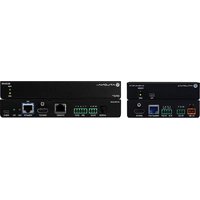


- Support and Community
- Regulatory and Legal
- Trademarks
- Contents
- Chapter 1 Get Started with the Main UI
- Chapter 2 Congure Switch System Information
- AV Line of Fully Managed Switches M4250 Series Main User Manual
- Chapter 3 Congure Switching Information
- Chapter 4 Manage Routing
- Chapter 5 Congure Multicast Routing
- Chapter 6 Congure Quality of Service
- Chapter 7 Manage Switch Security
- Chapter 8 Monitor the Switch and Network
- Chapter 9 Maintenance and Troubleshooting
- Appendix A Conguration Examples
- Appendix B Software Default Settings and Hardware Specifications
- 1
- Get Started with the Main UI
- Supported switches
- Available publications and online help
- Register your product
- To register your switch with NETGEAR:
- Main local browser UI overview
- Log in to the main UI with a web br
- To use the switch default IP address to access the switch over the main UI:
- To use a known IP address to access the switch over the main UI:
- Main UI buttons and user-dened elds
- Interface naming conventions
- Save your settings to the running conguration
- Main UI online help
- To access the online support link:
- Use the Device View in the Main UI
- To use the Device View:
- Set up SNMP access
- To configure authentication and encryption settings for the SNMPv3 admin profile:
- 2
- Congure Switch System Information
- Switch system information
- View and congure switch system information
- To view and dene system information:
- Select System > Management > System Information.
- Dene the following elds:
- View the fan status
- To view the fan status:
- View the temperature sensor information
- To view temperature information:
- View the device status and rmware version
- To view the device status and rmware version:
- View the system CPU status
- To view the system CPU status:
- Congure the CPU thresholds
- To congregate the CPU thresholds:
- View or clear switch statistics
- To view or clear the switch statistics:
- View USB device information
- To display the USB device information:
- Loopback interface
- To congregate a loopback interface:
- IPv4 management interfaces and VLANs
- Congure the IPv4 service port
- To congregate the IPv4 service port:
- Click the Apply button.
- To save the settings to the running conguration, click the Save icon.
- Congure an IPv4 management VLAN
- To congregate an IPv4 management VLAN or reset the IPv4 management VLAN:
- Congure an IPv4 management interface
- To congregate an IPv4 management interface:
- IPv6 management interfaces and VLANs
- Congure an IPv6 service port
- To congregate the IPv6 service port:
- Manage IPv6 addresses for the IPv6 service port
- To add or remove an IPv6 address for the IPv6 service port:
- Congure an IPv6 management VLAN
- To congregate an IPv6 management VLAN or reset the IPv6 management VLAN:
- Manage IPv6 addresses for the IPv6 management VLAN
- To add or remove an IPv6 address for the IPv6 management VLAN:
- Congure an IPv6 management interface
- To congure an IPv6 management interface:
- To add or remove an IPv6 address for the IPv6 management interface:
- To add or remove an IPv6 default route address for the IPv6 management interface
- Time and SNTP settings
- Congure the time setting manually
- To congregate the time setting manually
- Congure the time settings with SNTP and congregate the global SNTP settings
- To congregate the time by using SNTP and congregate the global SNTP settings:
- View the SNTP global status
- To view SNTP global status:
- Congure SNTP servers
- Remove an SNTP server To remove an SNTP server:
- Congure daylight saving time settings
- View the daylight saving time status
- To view the daylight saving time status:
- Precision Time Protocol
- Manage the global PTP settings
- To congregate the PTP end-to-end transparent clock settings globally:
- Manage the PTP interface settings
- To congregate the PTP end-to-end transparent clock settings for one or more interfaces:
- Domain Name System
- To congregate the global DNS settings and add a DNS server:
- Remove a DNS server
- To remove a DNS server:
- Switch database management template
- To change the SDM template
- Green Ethernet settings
- Congure the global green Ethernet settings
- To congregate the global green Ethernet settings:
- Congure green Ethernet interface settings
- To congregate the green Ethernet interface settings:
- To display the green Ethernet information for the link partner of an interface:
- Display the green Ethernet statistics summary
- To display the green Ethernet statistics summary:
- Bonjour settings
- Display Bonjour information
- To display Bonjour information:
- IPv4 DHCP server
- Congure a DHCP server
- To congure a DHCP server:
- Manage DHCP pools
- Change a DHCP pool You can change an existing DHCP pool. To change a DHCP pool:
- Remove a DHCP pool You can remove a DHCP pool that you no longer need. To remove a DHCP pool:
- Congure DHCP pool options
- To congregate DHCP pool options:
- Display DHCP server statistics
- To display the DHCP server statistics:
- Display the DHCP bindings
- To display the DHCP bindings:
- Delete one or all dynamic DHCP bindings
- To delete one or all dynamic DHCP bindings:
- View bindings with DHCP conicts
- To view DHCP bindings with conicts:
- Delete one or all DHCP bindings with conicts
- To delete one or all DHCP bindings with conicts:
- DHCP relay and relay statistics
- To congregate a DHCP relay and display relay statistics:
- DHCP Layer 2 relay
- Congure the global DHCP L2 relay settings
- To congregate the global DHCP L2 relay settings:
- Congure a DHCP L2 relay interface
- To congure DHCP L2 relay interface:
- Display DHCP L2 relay interface statistics
- To display the DHCP L2 relay interface statistics:
- UDP relay
- To congregate the global UDP relay settings and add a UDP switch conguration:
- Change a UDP switch conguration
- To change a UDP switch conguration:
- Remove a UDP switch conguration
- To remove a UDP switch conguration:
- Add a UDP interface conguration
- To add a UDP relay interface conguration:
- Change a UDP interface conguration
- DHCPv6 server
- Enable the DHCPv6 server
- To enable the DHCPv6 server on the switch:
- Manage DHCPv6 pools
- To create a DHCPv6 pool:
- Change a DHCPv6 pool You can change an existing DHCPv6 pool. To change a DHCPv6 pool:
- Delete a DHCPv6 pool You can delete a DHCPv6 pool that you no longer need. To delete a DHCPv6 pool:
- Manage DHCPv6 prex delegation for pools
- Congure the DHCPv6 settings for an interface
- To congregate the DHCPv6 settings for an interface:
- Display the DHCPv6 bindings
- To display DHCPv6 bindings information:
- Display DHCPv6 server statistics
- To display DHCPv6 server statistics:
- Select System > Services > DHCPv6 Server > DHCPv6 Server Statistics.
- Do one of the following:
- To refresh the page, click the Refresh button.
- Delete DHCPv6 statistics for one or all interfaces
- To delete DHCPv6 statistics for one or all interfaces:
- DHCPv6 relay interface
- To congregate an interface as a DHCPv6 relay:
- Power over Ethernet
- PoE concepts
- Congure the global PoE settings
- To congregate the global PoE setting:
- Congure the PoE ports settings
- To congregate the PoE ports settings:
- Power-cycle one or more PoE ports
- To power-cycle one or more PoE ports:
- Timer schedules
- Create a timer schedule
- To create a timer schedule:
- Specify the settings for a recurring timer schedule
- To specify the settings for a timer schedule that uses a recurring pattern:
- To change the settings for an existing recurring timer schedule entry:
- Delete a timer schedule entry
- To delete a timer schedule entry:
- Delete a timer schedule
- To delete a timer schedule:
- Simple Network Management Protocol
- Manage SNMPv1 and SNMPv2 communities
- To add an SNMPv1 and SNMPv2 community:
- To delete an SNMPv1 and SNMPv2 community:
- To add an SNMPv1 or SNMPv2 trap conguration for a host:
- To delete an SNMPv1 or SNMPv2 trap conguration for a host:
- Congure SNMPv1 and SNMPv2 trap ags
- To congure the trap ags:
- Display the supported MIBs
- To display the MIBs supported by the switch:
- Manage SNMPv3 users
- Add an SNMPv3 user account You can add an SMPv3 user account. To add an SNMPv3 user account:
- To change an existing SNMPv3 user account:
- To delete an SNMPv3 user account:
- Link Layer Discovery Protocol
- Congure the global LLDP settings
- To congregate the global LLDP settings:
- Congure LLDP interface settings
- To congure LLDP interface settings:
- Display or clear LLDP statistics
- To display or clear LLDP statistics:
- Display LLDP local device information
- To display LLDP local device information:
- Display LLDP remote device information
- To display LLDP remote device information:
- Display the LLDP remote device inventory
- To display the LLDP remote device inventory:
- Link Layer Discovery Protocol for Media Endpoint Devices
- Congure the global LLDP-MED settings
- To congregate the global LLDP-MED settings:
- Congure LLDP-MED interface settings
- To congure LLDP-MED interface settings:
- Display LLDP-MED local device information
- To display LLDP-MED local device information:
- Display the LLDP-MED remote device information
- To display the LLDP-MED remote device information:
- Display the LLDP-MED remote device inventory
- To display the LLDP-MED remote device inventory:
- Link dependency
- Congure a link dependency group
- To congregate a link dependency group:
- To configure or display upstream and downstream interfaces for a link dependency group:
- Clear all interfaces in a link dependency group
- To clear all interfaces in a link dependency group:
- Industry Standard Discovery Protocol
- Congure the global ISDP settings
- To congregate the global ISDP settings:
- Congure ISDP settings for an interface
- To congregate ISDP settings for an interface:
- To display or clear ISDP neighbor information:
- Display or clear ISDP statistics
- To display or clear ISDP statistics:
- 3
- Congure Switching Information
- VLANs
- Manage the VLAN configuration on the switch
- To add a VLAN:
- To change a VLAN:
- To delete one or more VLANs:
- To reset the entire VLAN congruration to default settings:
- To change the internal VLAN allocation settings:
- Auto-Trunk overview
- Enable or disable Auto-Trunks
- To enable or disable Auto-Trunks:
- Congure the switch port mode settings for interfaces
- To congregate the switch port mode settings for interfaces:
- To congregate membership interfaces for a VLAN:
- View the VLAN status on the switch
- To view the VLAN status on the switch:
- Change the port VLAN ID settings
- To congregate the PVID and PVID-related settings:
- Congure a MAC-based VLAN
- Add a MAC-based VLAN conguration To add a MAC-based VLAN conguration:
- Add a protocol-based VLAN group You can add a protocol-based VLAN group. To add a protocol-based VLAN group:
- To change a protocol-based VLAN group:
- To delete a protocol-based VLAN group:
- Congure membership interfaces for a protocol-based VLAN group
- To congure membership interfaces for a protocol-based VLAN group:
- Congure an IP subnet-based VLAN
- Add an IP subnet-based VLAN You can add an IP subnet-based VLAN. To add an IP subnet-based VLAN:
- To delete an IP subnet-based VLAN:
- Congure a double VLAN
- To congregate the global EtherType for the DVLAN and congregate the DVLAN on one or more interfaces:
- Congure a voice VLAN
- To congure a voice VLAN:
- Congure Generic Attribute Registration Protocol
- To congure GARP switch settings:
- To congure GARP settings for one or more interfaces:
- Auto-VolP
- Congure Auto-VoIP protocol-based settings
- To congregate protocol-based settings for one or more interfaces:
- Congure the Auto-VolP OUI-based properties
- To congregate the Auto-VoIP OUI-based properties:
- To congregate the OUI-based interface settings:
- Manage the OUI table
- Add an OUI prex To add an OUI prex:
- Delete one or more OUI prexes To delete one or more OUI prexes:
- Display the Auto-VoIP status
- To display the Auto-VoIP status:
- Spanning Tree Protocol
- To congregate the STP settings and display the STP status:
- To congregate the CST settings and display the CST status:
- Congure the CST interface settings
- To congregate the CST interface settings:
- Display the CST interface Status
- To display the CST interface status:
- Manage MST instances
- To add an MST instance and display the MST status:
- Select Switching > STP > Advanced > MST Conguration.
- Congure the settings for the MST instance:
- Click the Add button
- Change an MST instance You can change an existing MST instance. To change an existing MST instance:
- Delete an MST instance You can delete an MST instance that you no longer need To delete an MST instance:
- Congure and display the interface settings for an MSI instance
- To congure and display the port settings for an MST instance:
- Display the STP interface statistics
- To display the STP interface statistics:
- Congure the PVST/RPVST VLAN settings
- To congregate the PVST/RPVST VLAN settings for the switch:
- Change a PVST/RPVST VLAN conguration
- To change an existing PVST/RPVST VLAN conguration:
- Remove a PVST/RPVST VLAN conguration
- To delete a PVST/RPVST VLAN conguration:
- Congure the PVST and RPVST interface settings
- To congregate the PVST and RPVST interface settings:
- Display the PVST and RPVST statistics
- To display the PVST and RPVST statistics:
- Multicast forwarding database
- To display the entries in the multicast forwarding database:
- To remove the IGMP snooping entries from the multicast forwarding database:
- Display the multicast forwarding database statistics
- To display the multicast forwarding database statistics:
- Internet Group Management Protocol snooping
- Congure IGMP snooping automatically with IGMP Plus mode
- To congure IGMP snooping automatically:
- Congure IGMP snooping manually
- To congregate the settings for IGMP snooping manually:
- Congure the IGMP snooping settings for interfaces
- To congregate the IGMP snooping settings for interfaces:
- Congure IGMP snooping for VLANs automatically with IGMP Plus mode
- To congregate IGMP snooping for VLANs automatically:
- Congure IGMP snooping for VLANs manually
- To congregate the settings for IGMP snooping for a VLAN manually:
- Congure an IGMP multicast router interface
- To congregate a multicast router interface:
- Congure an IGMP multicast router VLAN
- To congregate a multicast router VLAN:
- IGMP snooping querier overview
- Congure the IGMP snooping querier global settings
- To congregate the global settings for an IGMP snooping querier:
- To congregate an IGMP snooping querier for a VLAN:
- To remove the IGMP snooping querier settings for a VLAN:
- To display the status of the IGMP snooping querier:
- Multicast Listener Discovery snooping
- Congure MLD snooping automatically with MLD Plus mode
- To congure MLD snooping automatically:
- Congure MLD snooping manually
- To congregate the settings for MLD snooping manually:
- To congregate the MLD snooping settings for interfaces:
- Configure MLD snooping for VLANs automatically with N Plus mode
- To congregate MLD snooping for VLANs automatically:
- Congure MLD snooping for VLANs manually
- To congregate the settings for MLD snooping for a VLAN manually:
- To remove the MLD snooping querier settings for a VLAN:
- Congure an MLD multicast router interface
- To congregate an MLD multicast router interface:
- Congure an MLD multicast router VLAN
- Congure the MLD snooping querier global settings
- To congregate the global settings for an MLD snooping querier:
- Congure an MLD snooping querier for a VLAN
- To congregate an MLD snooping querier for a VLAN:
- Multicast VLAN registration
- Congure the global MVR settings
- To congregate the global MVR settings:
- Congure an MVR group
- To congure an MVR group:
- Remove an MVR group
- To remove an MVR group:
- Congure an MVR interface
- To congure an MVR interface:
- To congregate the interface members of an MVR group:
- Display the MVR statistics
- To display the MVR statistics:
- MAC address table
- To view, search, or clear the MAC address table:
- Set the dynamic address aging interval
- To set the dynamic address aging interval:
- To add a static MAC address to the MAC address table:
- To remove a static MAC address from the MAC address table:
- Port settings
- Congure and display the port settings
- To congure and display the port settings:
- To add port, LAG, and VLAN descriptions:
- Display transceiver module information
- To view transceiver module information:
- Congure the port link ap settings
- To congregate the port link ap settings:
- Link aggregation groups
- Auto-LAG overview
- Enable or disable Auto-LAGs
- To enable or disable Auto-LAGs:
- Congure the hash mode for Auto-LAGs
- To change the hash mode for the Auto-LAGs:
- Congure the LAG settings
- To congregate the LAG settings:
- Congure a single LAG and its membership
- To congregate a single LAG and its membership:
- 802.1AS timing and synchronization
- Congure and view the global 802.1AS settings
- To congregate and view the global 802.1AS settings on the switch:
- Congure the 802.1AS interface settings
- To congregate the 802.1AS interface settings:
- View the 802.1AS statistics
- To view the 802.1AS statistics for the interfaces:
- Multiple Registration Protocol settings
- Congure the global MRP settings
- To congregate the global MRP settings:
- Congure 802.1Qav mapping
- To change the 802.1Qav mapping priorities:
- Congure the MRP interface settings
- To congure MRP interface settings:
- View or clear MMRP statistics
- To view and clear MMRP statistics:
- View or clear MVRP statistics
- To view and clear MVRP statistics:
- View or clear MSRP statistics
- To view and clear MSRP statistics:
- View the MSRP reservation settings
- To view the MSRP reservation settings:
- Congure and view the Qav settings for interfaces
- To congure view the Qav settings for interfaces:
- View MSRP streams information
- To view MSRP streams information:
- Loop protection
- About loop protection
- Congure the global loop protection settings
- To globally enable and congregate loop protection:
- To enable and congregate loop protection for an interface and display the loop protection state on the switch:
- 4
- Manage Routing
- Routing concepts
- Routing table, routes and route preference
- Congure a route and display learned routes
- To add or change a route and display learned routes:
- Delete a route
- To delete a route:
- Specify route preferences
- To specify route preferences
- IPv4 routing
- Manage the global IPv4 routing settings
- To congregate the global IPv4 routing settings:
- Display the IPv4 statistics
- To display the IPv4 routing statistics for the switch:
- Congure IPv4 routing interfaces
- To congure one or more IPv4 routing interfaces:
- To delete the routing IP address from one or more IPv4 routing interfaces:
- To congregate the secondary IP address:
- Delete the secondary IP address from an IPv4 routing interface
- To delete the secondary IP address from an IPv4 routing interface:
- IPv6 routing
- Manage the global IPv6 routing settings
- To congregate the global IPv6 routing settings:
- Display the IPv6 route table
- To display the IPv6 route table:
- Congure IPv6 routing interfaces
- To congure one or more IPv6 routing interfaces:
- Congure prex settings for an IPv6 routing interface
- To add or change prex settings for an IPv6 routing interface:
- To a delete prex settings from an IPv6 routing interface:
- To display the IPv6 and ICMPv6 statistics for an IPv6 routing interface:
- To display the IPv6 neighbor table or clear IPv6 neighbor entries:
- Congure IPv6 static routes
- To add or change a static IPv6 route:
- Delete an IPv6 static route
- To delete an IPv6 static route:
- Congure the IPv6 route preference for the switch
- Congure the IPv6 route preference for the switch:
- Congure IPv6 tunnels
- To add a new IPv6 tunnel or change an existing IPv6 tunnel:
- Delete an IPv6 tunnel
- To delete an IPv6 tunnel:
- Routing VLANs
- Create a routing VLAN with the VLAN static routing
- To create a routing VLAN with the VLAN static routing wizard:
- Congure routing for an existing VLAN
- To add or change routing for an existing VLAN:
- Remove the routing function from a VLAN
- To a remove the routing function from a VLAN:
- Address Resolution Protocol
- Display the ARP entries in the ARP cache
- To display the ARP entries in the ARP cache:
- Delete a static ARP entry
- To delete a static ARP entry:
- Congure the ARP table settings or remove entries from the table
- To congregate the ARP table settings or remove entries from the table:
- Routing Information Protocol
- Enable or disable RIP on the switch
- To enable or disable RIP on the switch:
- Congure the global RIP settings for the switch
- To congregate global RIP settings for the switch:
- Congure RIP interface settings
- To congure RIP interface settings:
- Click the Apply button.
- Router discovery and router advertisements
- To congregate router discovery for a routing interface:
- 5
- Congure Multicast Routing
- IPv4 multicast routing and the IPv4 multi route table
- Display the IPv4 multicast route table
- To display the IPv4 Mroute table:
- To add a static multicast entry to the IPv4 Mroute table:
- Delete a static multicast entry from the IPv4 Mroute
- To delete a static multicast entry from the IPv4 Mroute table:
- Congure global multicast settings for the switch
- To congregate global multicast settings for the switch:
- Congure a multicast interface
- To congure a multicast interface:
- IGMP for IPv4 multicast routing
- Congure the global IGMP settings for the switch
- To congregate global IGMP settings for the switch:
- Congure an IGMP routing interface
- To congregate an IGMP routing interface:
- To display the statistics for the IGMP routing interfaces:
- To display the IGMP groups and search the IGMP group database:
- Display the IGMP membership information and search IGMP membership database
- To display the IGMP membership information and search the IGMP membership database:
- Congure an IGMP proxy interface
- To congregate an IGMP proxy interface:
- To display the statistics for the IGMP proxy interface:
- To display the IGMP proxy membership information and search the IGMP proxy membership database:
- PIM for IPv4 multicast routing
- Congure the global PIM IPv4 settings on the switch
- To congregate the global PIM IPv4 settings on the switch:
- Add IPv4 PIM-SSM groups
- To add an IPv4 PIM-SSM group:
- Delete an IPv4 PIM-SSM group
- To delete an IPv4 PIM-SSM group:
- Congure an IPv4 PIM interface
- To congregate an IPv4 PIM interface:
- Display IPv4 PIM neighbors and search the PIM neigh database
- To display IPv4 PIM neighbors and search the PIM neighbors database:
- To add an IPv4 PIM candidate RP conguration:
- Delete an IPv4 PIM candidate rendezvous point conguration
- To delete an IPv4 PIM candidate RP conguration:
- Congure an interface as an IPv4 PIM bootstrap router candidate
- To congregate an interface as an IPv4 PIM BSR candidate:
- To delete an IPv4 PIM BSR candidate conguration from an interface:
- To add or change a static IPv4 PIM RP for a group:
- To delete a static IPv4 PIM RP conguration for a group:
- Static multicast routes for IPv4 addresses
- Congure static multicast routes for IPv4 addresses
- To add or change a static IPv4 multicast route:
- To delete a static IPv4 multicast route:
- Multicast admin boundaries for IPv4 addresses
- To congregate an interface as a multicast admin boundary:
- To delete a multicast admin boundary conguration:
- IPv6 multicast routing and the IPv6 multi route table
- Display the IPv6 multicast route table
- To display the IPv6 Mroute table:
- PIM for IPv6 multicast routing
- To congregate the global PIM IPv6 settings on the switch:
- Add IPv6 PIM-SSM groups
- To add an IPv6 PIM-SSM group:
- Delete an IPv6 PIM-SSM group
- To delete an IPv6 PIM-SSM group:
- Congure an IPv6 PIM interface
- To congure an IPv6 PIM interface:
- Display IPv6 PIM neighbors and search the PIM neigh database
- To display IPv6 PIM neighbors and search the PIM neighbors database:
- To add an IPv6 PIM candidate RP conguration:
- Delete an IPv6 PIM candidate rendezvous point conguration
- To delete an IPv6 PIM candidate RP conguration:
- To congregate an interface as an IPv6 PIM BSR candidate:
- To delete an IPv6 PIM BSR candidate conguration from an interface:
- To add or change a static IPv6 PIM RP for a group:
- To delete a static IPv6 PIM RP conguration for a group:
- MLD for IPv6 multicast routing
- Congure the global MLP settings for the switch
- To congregate the global MLP settings for the switch:
- Congure an MLD routing interface
- To congregate an MLD routing interface:
- To display the statistics for the MLD routing interfaces:
- To display the MLD groups and search the MLD group database:
- Display or clear MLD trafc statistics
- To view or clear IPv6 MLD trafc statistics:
- Congure an MLD proxy interface
- To congregate an MLD proxy interface:
- To display the statistics for the MLD proxy interface:
- To display the MLD proxy membership information and search the MLD proxy membership database:
- Static multicast routes for IPv6 addresses
- Congure static multicast routes for IPv6 addresses
- To add or change a static IPv6 multicast route:
- To delete a static multicast route:
- 6
- Congure Quality of Service
- Quality of Service concepts
- Class of Service
- CoS conguration concepts
- Congure the CoS trust mode settings globally or for specific interface
- To congregate the CoS trust mode settings on all interfaces or on a specific interface:
- Map 802.1p priorities to queues
- To map 802.1p priorities to queues for all interfaces or individual interfaces
- Map DSCP values to queues
- To map DSCP values to queues:
- Congure the CoS interface settings for an interface
- To congure CoS settings for an interface:
- Congure CoS queue settings for an interface
- To congregate the CoS queue settings for an interface:
- Configure the CoS WRED precedence settings for dropp packets
- To congure CoS WRED precedence settings for dropping packets:
- Differentiated Services
- Dening DiffServ
- DiffServ wizard overview
- To use the DiffServ wizard to create a trafc class and policy for one or more interfaces:
- Congure the DiffServ mode and display the entries in DiffServ private MIB tables
- To congregate the DiffServ mode and display the entries in the DiffServ private MIB tables:
- Congure a DiffServ class
- Rename an existing DiffServ class To rename an existing DiffServ class:
- Change the criteria for an existing DiffServ class To change the criteria for an existing DiffServ class:
- Congure an IPv6 DiffServ class
- Delete an IPv6 DiffServ class
- Congure a DiffServ policy
- Create and congregate a DiffServ policy To create and congregate a DiffServ policy:
- Delete a DiffServ policy To delete a DiffServ policy:
- Congure the DiffServ service interface
- Remove one or both DiffServ policies from an interface To remove one or both DiffServ policies from an interface:
- Display DiffServ service statistics
- To display DiffServ service statistics:
- 7
- Manage Switch Security
- User accounts and passwords
- Add or change a user account
- To add or change a user account:
- Delete a user account
- To delete a user account:
- Congure user password requirements
- To congure user password requirements:
- Change the privileged EXEC CLI password
- To change the privileged EXEC CLI password for use in the CLI:
- To congregate the console, Telnet, or SSH password:
- RADIUS servers
- To congregate the global RADIUS server settings:
- Congure a RADIUS authentication server on the switch
- Add a RADIUS authentication server to the switch To add a RADIUS
- Modify the settings for a RADIUS authentication server on the switch
- Congure a RADIUS accounting server
- TACACS+ servers
- Congure the global TACACS+ settings
- To congregate the global TACACS+ settings:
- Add a TACACS+ server to the switch
- To add a TACACS+ server to the switch:
- Modify the settings for a TACACS+ server on the sw To modify the settings for a TACACS+ server on the switch:
- To remove a TACACS+ server from the switch:
- Authentication lists
- Congure a login authentication list
- To congure a login authentication list:
- Delete a login authentication list
- To delete a login authentication list:
- Congure an enable authentication list
- To congregate an enable authentication list:
- Delete an enable authentication list
- To delete an enable authentication list:
- Congure the Dot1x authentication list
- To congregate the dot1x authentication list:
- Select Security > Management Security > Authentication List > Dot1x Authentication List.
- Congure the HTTP authentication list
- To congregate the HTTP authentication list:
- Congure the HTTPS authentication List
- To congregate the HTTPS authentication list:
- Current login sessions
- To display the current login sessions:
- Select Security > Management Security > Login Sessions.
- HTTP and HTTPS management access
- Congure HTTP access settings
- To congregate the HTTP access settings:
- Congure the HTTPS access settings
- To congregate the HTTPS access settings:
- Browser security message with HTTPS access
- Manage certificates for HTTPS access
- To display the status of the SSL certificates:
- To generate an SSL certificate:
- To activate a certificate:
- Delete an SSL certificate
- To delete an SSL certificate:
- To transfer an HTTPS certificate to the switch:
- SSH management access
- Congure the global SSH access settings
- To congure SSH settings:
- Manage RSA and DSA keys for SSH access
- Generate an RSA or DSA key
- To generate an RSA or DSA key:
- Delete an RSA or DSA key
- To delete an RSA or DSA key:
- To transfer SSH keys to the switch:
- Telnet management access
- Select Telnet authentication lists
- To congregate the Telnet authentication lists:
- Congure Inbound Telnet settings
- To congregate the inbound Telnet settings:
- Congure outbound Telnet settings
- To congregate the outbound Telnet settings:
- Console port management access
- To congregate the console port settings:
- Denial of service
- To congure individual DoS settings:
- Management access proles and rules
- Add an access prole
- To add an access prole:
- Add a rule to the access prole
- To add a rule to the access prole:
- Activate the access prole
- To activate the access prole:
- To display the access prole summary and the number of Itered packets:
- Deactivate an access prole
- To deactivate an access prole:
- Remove an access prole
- To remove an access prole:
- Port authentication
- Congure the global 802.1X settings
- To congregate the global 802.1X settings:
- Manage port authentication on individual ports
- To congure 802.1X settings for a port:
- To initialize 802.1X on a port:
- Display the port summary
- To display the port summary:
- Select Security > Port Authentication > Advanced > Port Summary.
- To refresh the page, click the Refresh button.
- Display the client summary
- To display the client summary:
- MAC Iters for trafc control
- Create a MAC Iter
- To create a MAC Iter:
- Delete a MAC Iter
- To delete a MAC Iter:
- Display the MAC Iter summary
- To display the MAC Iter summary:
- Port security
- Congure the global port security mode
- To congregate the global port security mode:
- Congure a port security interface
- To congregate port security settings:
- Display learned MAC addresses and convert them to addresses
- To display learned MAC addresses for an individual interface or LAG and convert these MAC addresses to static MAC addresses:
- Private port groups
- Add a private port group
- To add a private port group:
- Remove a private port group
- To remove a private port group:
- Congure the membership of a private port group
- To congregate the membership of a private port group:
- Protect ports
- To congure protected ports:
- Private VLANs
- Overview of the tasks for private VLAN conguration
- Assign a private VLAN type to a VLAN
- To assign a private VLAN type to a VLAN:
- Congure a private VLAN association with a primary ar secondary VLAN
- To congregate a private VLAN association with a primary and secondary VLAN:
- Remove an existing private VLAN association
- To remove a private VLAN association:
- Congure the private VLAN port mode
- To congregate the private VLAN port mode:
- To remove a private VLAN host interface from primary and secondary VLANs:
- To assign a private VLAN promiscuous interface to a primary VLAN and secondary VLANs:
- To remove primary and secondary VLANs from a private VLAN isolated trunk interface:
- Congure native and allowed VLANs on a private VLAN trunk interface
- To congregate native and allowed VLANs on a private VLAN trunk interface:
- Storm control
- Congure global storm control settings
- To congregate global storm control settings:
- To congregate storm control settings for one or more ports:
- DHCP snooping
- Enable DHCP snooping for the switch
- To globally enable DHCP snooping for the switch:
- Enable DHCP snooping for a VLAN
- To enable DHCP snooping for a VLAN:
- Congure DHCP snooping interface settings
- To congure DHCP snooping interface settings:
- Add a static DHCP binding and display dynamic DHC bindings
- To add a static DHCP binding and display or clear the dynamic bindings:
- Remove a static DHCP binding
- To remove a static DHCP binding:
- Congure DHCP snooping persistent settings
- To congure DHCP snooping persistent settings:
- Display or clear DHCP snooping statistics
- To display or clear the DHCP snooping statistics:
- DHCPv6 snooping
- Enable DHCPv6 snooping for the switch
- To globally enable DHCPv6 snooping for the switch:
- Enable DHCPv6 snooping for a VLAN
- To enable DHCPv6 snooping for a VLAN:
- Congure DHCPv6 snooping interface settings
- To congure DHCPv6 snooping interface settings:
- Add a static DHCPv6 binding and display dynamic Df bindings
- To add a static DHCPv6 binding and display or clear the dynamic bindings:
- Remove a static DHCPv6 binding
- To remove a static DHCPv6 binding:
- Congure DHCPv6 snooping persistent settings
- To congure DHCPv6 snooping persistent settings:
- Display or clear DHCPv6 snooping statistics
- To display or clear the DHCPv6 snooping statistics:
- IP source guard interfaces
- Congure IP source guard on an interface
- To congure IP source guard on an interface:
- To add a static IPSG binding and display or clear the dynamic bindings:
- To remove a static IPSG binding:
- IPv6 source guard interfaces
- Congure IPv6 source guard on an interface
- To congregate IPv6 source guard on an interface:
- To add a static IPv6SG binding and display or clear the dynamic bindings:
- To remove a static IPv6SG binding:
- Dynamic ARP inspection
- Congure the global DAI settings
- To congregate the global DAI settings:
- Congure DAI VLANs
- To congure one or more DAI VLANs:
- Congure DAI interfaces
- To congregate one or more DAI interfaces:
- Create a DAI access control list
- To create a DAI ACL:
- Congure a rule for an existing DAI ACL
- To congregate a rule for an existing DAI ACL:
- To delete a rule from an existing DAI ACL:
- Delete a DAI access control list
- To delete a DAI ACL:
- Display the DAI statistics
- To display the DAI statistics:
- Captive portals
- Congure the global captive portal settings
- To congregate the global captive portal settings:
- Congure a captive portal
- To congregate a captive portal instance:
- Delete a captive portal
- To delete a captive portal:
- Congure a captive portal binding
- To congregate a captive portal binding:
- Display or delete captive portal bindings in the captiv portal binding table
- To display or delete captive portal bindings:
- Congure captive portal groups
- To add a captive portal group:
- Remove a captive portal group To remove a captive portal group:
- Congure captive portal users
- To delete a captive portal user account:
- Congure the captive portal trap ag settings
- To congregate the captive portal trap ag settings:
- To display or clear the captive portal client statistics:
- Access control lists
- To congure an ACL:
- Use the ACL Wizard to create a simple ACL
- Use the ACL Wizard to create an ACL To use the ACL Wizard to create an A
- FieldsACL Based On
- Congure a MAC ACL
- Change the name of a MAC ACL To change the name of a MAC ACL:
- Delete a MAC ACL To delete a MAC ACL:
- Congure MAC ACL rules
- Congure MAC bindings
- To congure MAC binding:
- To display or delete MAC ACL bindings:
- Congure a basic or extended IPv4 ACL
- Delete an IPv4 ACL To delete an IPv4 ACL:
- Congure rules for a basic IP ACL
- Click the Add button.
- Specify the following match criteria for the rule:
- Congure rules for an extended IPv4 ACL
- Add a rule for an extended IPv4 ACL To add a rule for an extended IPv4 A0
- Congure the following options for the rule:
- Modify the match criteria for an extended IPv4 ACL rule To modify the match criteria for an existing extended IPv4 ACL rule:
- Congure an IPv6 ACL
- Add an IPv6 ACL To add an IPv6 ACL:
- Change the name of an IPv6 ACL To change the name of an IPv6 ACL:
- Delete an IPv6 ACL To delete an IPv6 ACL:
- Congure rules for an IPv6 ACL
- Delete an IPv6 ACL rule To delete an IPv6 ACL rule:
- Congure IP ACL interface bindings
- To bind an IP ACL to one or more interfaces:
- To display or delete IP ACL bindings:
- Congure VLAN ACL bindings
- Add a VLAN ACL binding To add a VLAN ACL binding:
- Remove a VLAN ACL binding To remove a VLAN ACL binding:
- 8
- Monitor the Switch and Network
- Port and EAP packet statistics
- Display or clear port statistics
- To view or clear port statistics:
- Display or clear detailed statistics for a port
- To display and clear detailed statistics for a port:
- Display or clear EAP and EAPoL statistics
- To display or clear EAP and EAPoL statistics:
- Select Monitoring > Ports > EAP Statistics.
- Perform a cable test
- To perform a cable test:
- Logs
- Manage and display the memory log
- To manage and display the memory log:
- Message log format
- Enable or disable the command conguration log
- To enable or disable the command conguration log:
- Enable or disable console logging
- To enable or disable console logging:
- Syslog and log server host settings
- Congure the syslog settings
- To congregate the syslog settings:
- Add a syslog server
- To add a syslog server:
- To modify the settings for a remote syslog host:
- To delete the settings for a remote syslog host:
- Trap log
- To display or clear the trap log:
- Event log
- To display or clear the event log:
- Port mirroring
- To set up a port mirroring conguration:
- RSPAN VLANs and source and destination switches
- To congregate an existing VLAN as an RSPAN VLAN:
- Congure the switch as an RSPAN source switch
- To congregate the switch as an RSPAN source switch:
- To congregate the switch as an RSPAN destination switch:
- sFlow monitoring
- sFlow agent overview
- Congure the source interface for the sFlow agent
- To congregate the source interface for the sFlow agent:
- Congure an sFlow receiver
- To congregate an sFlow receiver:
- Click the Main UI Login button.
- Congure sFlow polling and sampling on an interface
- To congure sFlow polling and sampling on an interface:
- Display license information
- Display license key information
- To display license key information:
- Select System > Management > License Key.
- Display features to which the license applies
- To display features to which the license applies:
- 9
- Maintenance and Troubleshooting
- Save the conguration
- To save the conguration:
- Automatic installation of the congregation le
- Congure the auto install process
- To congregate the auto install process:
- Option 125 DHCP server requirements for obtaining ar conguration le through auto install
- Reboot the switch from the main local browser UI
- To reboot the switch:
- Reset the switch to the factory default settings
- To reset the switch to the factory default settings:
- Export a le from the switch
- Export a le from the switch to a server
- To export a le from the switch to a server:
- To use HTTP to export a le from the switch to a computer:
- Upgrade software or download a le
- Upgrade the software image or download a le from server to the switch
- To download a le to the switch from a server:
- Use HTTP to download a le to the switch or update software image
- To use HTTP to download from a computer to the switch:
- Download a le from a USB storage device to the sv
- To download a le from a USB storage device to the switch:
- Use an HTTP session to download and install an SSL certificate le on the switch
- To disable HTTPS and use an HTTP session to download and install an SSL security certificate le on the switch:
- Manage software images
- Copy an software image
- To copy a software image:
- Congure dual image settings
- Change the software image that loads when the switch starts or reboots
- Delete a software image To delete a software image:
- Diagnostics and troubleshooting
- Ping an IPv4 address
- To ping an IPv4 address:
- Ping an IPv6 address
- To ping an IPv6 address:
- Send an IPv4 traceroute
- To send an IPv4 traceroute:
- Send an IPv6 traceroute
- To send an IPv6 traceroute:
- Capture Packets
- To initiate packet capturing:
- Perform a full memory dump
- To perform a full memory dump:
- A
- Conguration Examples
- Virtual Local Area Networks (VLANs)
- VLAN conguration examples
- Access control lists (ACLs)
- MAC ACL sample conguration
- Basic IP ACL sample conguration
- Differentiated Services (DiffServ)
- Class
- DiffServ trafc classes
- Create policies
- DiffServ example conguration
- 802.1X access control
- 802.1X example conguration
- Multiple Spanning Tree Protocol
- MSTP example conguration
- VLAN routing interfaces
- B
- Software Default Settings and Hardware Specifications
- Access default settings for the switch device UI
- System features default settings
- Switching features default settings
- Routing and multicast features default settings
- QoS features default settings
- Security features default settings
- Monitoring features default settings
- Model-specific hardware technical specifications
- Model M4250-10G2XF-PoE+ (SKU GSM4212PX)
- M4250-10G2XF-PoE++ (SKU GSM4212UX)
- M4250-26G4F-PoE+ (SKU GSM4230P)
- M4250-26G4XF-PoE+ (SKU GSM4230PX)
- M4250-26G4F-PoE++ (SKU GSM4230UP)
- M4250-40G8F-PoE+ (SKU GSM4248P)
- M4250-40G8XF-PoE+ (SKU GSM4248PX)
- M4250-40G8XF-PoE++ (SKU GSM4248UX)
- M4250-12M2XF (SKU MSM4214X)
- M4250-16XF (SKU XSM4216F)
- General hardware technical specifications
Brand : Atlona
Model : NETGEAR-GSM
Category : Audio/video switch