HD-H1504K-SP - Audio/video switch FSR - Free user manual and instructions
Find the device manual for free HD-H1504K-SP FSR in PDF.

User questions about HD-H1504K-SP FSR
0 question about this device. Answer the ones you know or ask your own.
Ask a new question about this device
Download the instructions for your Audio/video switch in PDF format for free! Find your manual HD-H1504K-SP - FSR and take your electronic device back in hand. On this page are published all the documents necessary for the use of your device. HD-H1504K-SP by FSR.
USER MANUAL HD-H1504K-SP FSR
244 Bergen Blvd Woodland Park, NJ 07424 973-998-2300 www.fsrinc.com
Thank you for purchasing this product
For optimum performance and safety, please read these instructions carefully before connecting, operating, or adjusting this product. Please keep this manual for future reference.
Surge protection device recommended
This product contains sensitive electrical components that may be damaged by electrical spikes, surges, electric shock, lighting strikes, etc. Use of surge protection systems is highly recommended to protect and extend the life of your equipment.
Table of Contents
- Introduction....1
- Features....1
- Package Contents....2
- Specifications....2
- Operation Controls and Functions....4
- Introduction....1
- Features....1
- Package Contents....2
- Specifications....2
- Operation Controls and Functions....4
5.1 Transmitter Panel....4
5.2 Receiver Panel....5
5.3 IR Pin Definition....6 - Application Example....8
1. Introduction
This 18Gbps HDMI Extender can extend high-definition video / audio signals, RS-232, and bi-directional IR to a distance up to 492ft / 150 meters between the transmitter and receiver via a single CAT cable. It supports resolution up to 4K2K@60Hz 4:4:4, 18Gbps, HDCP 2.2. One HDMI loop-through port is available for a local output. The extender receiver de-embeds the audio for analog L/R output. In addition, the extender is equipped with two-way IR pass-through which allows for source and display control.
This HDMI extender set includes two units: transmitter and receiver. The transmitter is responsible for capturing HDMI input signal and carrying the signal via one cost effective Cat5e/6 cable and transmitting / emitting IR control signals. The receiver is responsible for receiving the HDMI signal and transmitting / emitting IR control signals.
The extender offers the most convenient solution for HDMI extension via a single Cat5e/6 with long distance capability and is the perfect solution for any application.
2. Features
☆ HDCP 2.2 / HDCP 1.4 and DVI 1.0 compliant
☆ Supports 18Gbps video bandwidth
☆ The maximum extended transmission distance via a single Cat5e/6 cable: 394ft / 120 meters for 4K2K signal, 492ft / 150 meters for 1080P signal
☆ Supports one HDMI loop output on the transmitter
☆ Extracts audio to analog stereo output on receiver
☆ With bi-directional IR, RS-232 and CEC pass-through
☆ HDR, HDR10+, Dolby Vision and HLG function supported
☆ Supports PoC (Power over Cable) function
☆ Compact design for easy and flexible installation
3. Package Contents
| Qty | Item |
| 1 | 18Gbps HDMI over HDBaseT Extender (Transmitter) |
| 1 | 18Gbps HDMI over HDBaseT Extender (Receiver) |
| 1 | IR Blaster cable (1.5 meters) |
| 1 | 20~60KHz IR Receiver cable (1.5 meters) |
| 4 | Mounting Ears |
| 2 | 3-pin pluggable screw terminal connectors |
| 1 | 24V/1A Locking Power adapter |
| 1 | User Manual |
4. Specifications
| Technical | |
| HDCP Compliance | HDCP 2.2 / HDCP 1.4 |
| Video Bandwidth | 18Gbps |
| Video Resolution | 4K2K 50/60Hz 4:4:44K2K 50/60Hz 4:2:24K2K 50/60Hz 4:2:04K2K 30Hz 4:4:41080p, 1080i, 720p, 720i, 480p, 480iAll HDMI 3D TV formatsAll PC resolutions including 1920 x 1200 |
| Color Space | RGB / YCbCr 4:4:4, YCbCr 4:2:2, YCbCr 4:2:0 |
| Color Depth | 8/10/12-bit (1080P60Hz, 4K30Hz, 4K60Hz YCbCr4:2:2/4:2:0)8-bit (4K60Hz 4:4:4 ) |
| HDMI Audio Formats | LPCM 2.0/2.1/5.1/6.1/7.1, Dolby Digital, DolbyTrueHD, Dolby Digital Plus(DD+), DTS-ES, DTSHD Master, DTS HD-HRA, DTS-X |
| L/R Audio Formats | PCM 2.0 |
| ESD Protection | Human body model — ±8kV (Air-gap discharge) &±4kV (Contact discharge) |
| Connection | |||
| Transmitter | Inputs: 1x HDMI Type A [19-pin female]Outputs: 1x HDMI Type A [19-pin female]1x HDBT OUT [RJ45, 8-pin female]Control: 1x IR IN [3.5mm Stereo Mini-jack]1x IR OUT [3.5mm Stereo Mini-jack]1x RS-232 [Pluggable screw terminal]1x SERVICE [Mini-USB, Update port] | ||
| Receiver | Inputs: 1x HDBT IN [RJ45, 8-pin female]Outputs: 1x HDMI Type A [19-pin female]1x AUDIO OUT [3.5mm Stereo Mini-jack]Control: 1x IR IN [3.5mm Stereo Mini-jack]1x IR OUT [3.5mm Stereo Mini-jack]1x RS-232 [Pluggable screw terminal]1x SERVICE [Mini-USB, Update port] | ||
| Mechanical | |||
| Housing | Metal Enclosure | ||
| Color | Black | ||
| Dimensions | Transmitter / Receiver:5.5" [W] x 2.56" [D] x 0.71" [H] | ||
| Weight | Transmitter: 160g, Receiver: 155g | ||
| Power Supply | Input: AC 100 - 240V 50/60HzOutput: DC 24V/1A (Locking connector) | ||
| Power Consumption | 9.36 W | ||
| Operating Temperature | 32 - 104°F / 0 - 40°C | ||
| Storage Temperature | -4 - 140°F / -20 - 60°C | ||
| Relative Humidity | 20 - 90% RH (no condensation) | ||
| Resolution / Distance | |||
| 4K2K | 394ft / 120M | ||
| 1080P | 492ft / 150M | ||
| Resolution / Cable Length | 4K60 - Feet / Meters | 4K30 - Feet / Meters | 1080P60 - Feet / Meters |
| HDMI IN / OUT | 16ft / 5M | 32ft / 10M | 50ft / 15M |
| The use of “Premium High-Speed HDMI” cable is highly recommended. | |||
5. Operation Controls and Functions
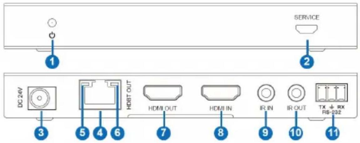
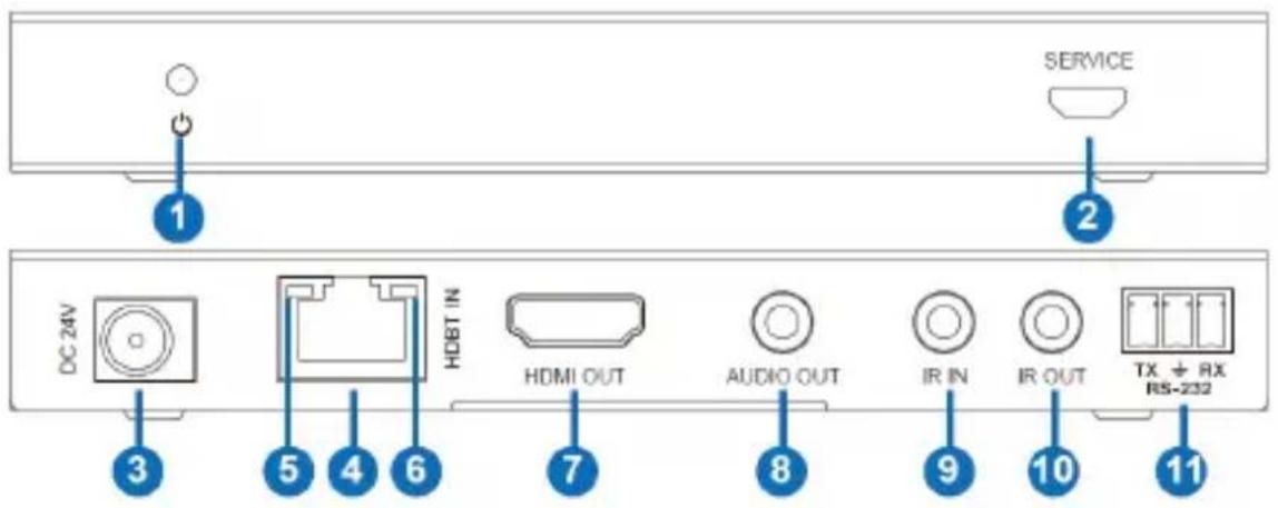
5.1 Transmitter Panel
text_image
SERVICE 1 2 DC 24V HDBT OUT HDMI OUT HDMI IN IR IN IR OUT TX ↓ RX RS-232 3 5 4 6 7 8 9 10 11| No. | Name | Function Description |
| 1 | Power LED | Red LED indicates that the transmitter is powered on. |
| 2 | SERVICE port | Firmware update port. |
| 3 | DC 24V | DC 24V/1A power supply input port.Note that the extender supports PoC function, it means that only 1 side, transmitter or receiver, needs to be powered by 24V/1A power adapter, the opposing side needs no power supply. |
| 4 | HDBT OUT | RJ45 connector for connecting the HDBT IN port of receiver with a CAT 5e/6 cable. |
| 5 | Connection Signal Indicator lamp | Illuminated: Transmitter and Receiver have a good connection.Flashing: Transmitter and Receiver have a poor connection.OFF: Transmitter and Receiver are not connected. |
| 6 | Data Signal Indicator lamp | Illuminated: HDMI signal with HDCP.Flashing: HDMI signal without HDCP.OFF: No HDMI signal. |
| 7 | HDMI OUT | HDMI loop output for local display. |
| 8 | HDMI IN | HDMI source input. |
| 9 | IR IN | IR input port for receiving the IR remote signal. |
| 10 | IR OUT | IR output port for control of source device. This IR output signal is from the IR IN port of receiver. |
| 11 | RS-232 | 3-pin Phoenix connector for RS-232 command transmission. The RS-232 command will pass-through from transmitter to receiver or from receiver to transmitter. |
5.2 Receiver Panel
text_image
SERVICE 1 2 DC 24V HDBT IN HDMI OUT AUDIO OUT IR IN IR OUT TX + RX RS-232 3 5 4 6 7 8 9 10 11| No. | Name | Function Description |
| 1 | Power LED | Red LED indicates that the receiver is powered on. |
| 2 | SERVICE port | Firmware update port. |
| 3 | DC 24V | DC 24V/1A power supply input port.Note that the extender supports PoC function, it means that only 1 side, transmitter or receiver, needs to be powered by 24V/1A power adapter, the opposing side needs no power supply. |
| 4 | HDBT IN | RJ45 connector for connecting the HDBT OUT port of transmitter with a CAT 5e/6 cable. |
| 5 | Connection Signal Indicator lamp | ▪ Illuminated: Transmitter and Receiver have a good connection.▪ Flashing: Transmitter and Receiver have a poor connection.▪ Dark: Transmitter and Receiver are not connected. |
| 6 | Data Signal Indicator | ▪ Illuminated: HDMI signal with HDCP.▪ Flashing: HDMI signal without HDCP.▪ Dark: No HDMI signal. |
| 7 | HDMI OUT | HDMI output for display. |
| 8 | AUDIO OUT | 3.5mm stereo connector for analog audio output. |
| 9 | IR IN | IR input port for receiving the IR remote signal. |
| 10 | IR OUT | IR output port for control of display device. This IR output signal is from the IR IN port of transmitter. |
| 11 | RS-232 | 3-pin Phoenix connector for RS-232 command transmission. The RS-232 command will pass-through from transmitter to receiver or from receiver to transmitter. |
5.3 IR Pin Definition
IR Receiver and Blaster pin's definition is as below:

natural_image
Close-up of two black cables with metallic connectors, no visible text or symbolsIR RECEIVER

natural_image
Close-up of two black cables with metallic connectors, no text or symbols visibleIR BLASTER
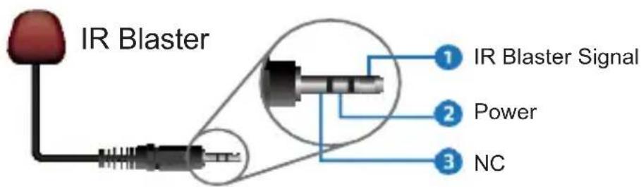
text_image
IR Blaster 1 IR Blaster Signal 2 Power 3 NC
text_image
IR Receiver 1 IR Signal 2 Power 3 GroundingThe following is an IR system diagram.

flowchart
graph TD
    subgraph Transmitter
        A["CC24V"] --> B["MT1 OUT"]
        B --> C["HCM OUT"]
        C --> D["HCM IN"]
        D --> E["IR IN"]
        E --> F["IR OUT"]
        F --> G["70.0 GB/INT"]
        G --> H["DVD"]
    end

    subgraph Receiver
        I["CC24V"] --> J["MT1 OUT"]
        J --> K["HD3OUT"]
        K --> L["A3DD OUT"]
        L --> M["IR IN"]
        M --> N["IR OUT"]
        N --> O["TV"]
    end

    subgraph IR Blaster Cable
        P["IR Blaster cable"] --> Q["TV"]
    end

    A --> R["TRANSMITTER"]
    J --> S["Receiver"]
    K --> T["IR Receiver cable"]
    L --> U["IR Blaster cable"]
    M --> V["IR In"]
    N --> W["IR OUT"]
Note: When the angle between the IR receiver and the remote control is ± 45^ , the transmission distance is 0-5 meters; when the angle between the IR receiver and the remote control is ± 90^ , the transmission distance is 0-8 meters.
CONTACT INFORMATION: FSR INC.
244 Bergen Blvd.
Woodland Park, NJ 07424
Phone: (973) 998-2300
*Order Desk Fax: (973) 785-4207
E-mail: sales@fsrinc.com
Web Site: http://www.fsrinc.com
- Application Example
