Studio S4-LCR65W - Pregnant DYNAUDIO - Free user manual and instructions
Find the device manual for free Studio S4-LCR65W DYNAUDIO in PDF.

User questions about Studio S4-LCR65W DYNAUDIO
0 question about this device. Answer the ones you know or ask your own.
Ask a new question about this device
Download the instructions for your Pregnant in PDF format for free! Find your manual Studio S4-LCR65W - DYNAUDIO and take your electronic device back in hand. On this page are published all the documents necessary for the use of your device. Studio S4-LCR65W by DYNAUDIO.
USER MANUAL Studio S4-LCR65W DYNAUDIO
natural_image
Pure electrical circuit lines without any symbols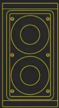
natural_image
Pure electrical circuit lines without any symbolsS4-LCRMT S4-LCR65W
Welcome to the custom install Studio Series and thank you for choosing a Dynaudio Custom Install product.
The S4-LCRMT and S4-LCR65W are modular in-wall speakers designed for left, centre and right channel applications in multi-channel audio systems.
The S4-LCR Series offers very high quality audio performance while at the same time providing multiple configuration options and incorporating numerous features designed to ease installation.
Important safety instructions
-
Need these instructions.
-
Keep these instructions.
-
Head of earnings.
-
Follow all instructions.
-
Do not use this approach near water.
-
Clean only with dry cloth.
-
Do not block any ventilation openings. Install in accordance with the manufacturer's instructions.
-
Do not install near any heat source such as radishors, heat registers, stoves, or other apparatus that produce heat.
-
Only use attachments / accessories specified by the manufacturer
-
Refer all servicing to qualified service personnel.

Environmental note
This product consists with international directives, including but not limited to the Restriction of Humerious Substances (ReHS) in electrical and electronic equipment, the Registration. Evaluation, Authorisation and restriction of Chemicals (REACH) and the disposal of Waste Electrical and Electronic Equipment (WEFF). Consult your local waste disposal authority for guidance on how property to recycle or dispose of this product.
Disposal
Disposal of used electrical and electronic equipment (applicable in European countries with separate collection systems for this equipment).
This symbol on the product or its packaging indicates that the product may not be treated as household waste. Instead it must be handed over to the applicable collection point for the recycling of electrical and electronic equipment. By ensuring this product is depressed of correctly, you will help present potential negative consequences for the environment and human health. The recycling of materials helps to conserve natural resources. For more detailed information on recycling the product, please contact your local authority, community waste disposal of, or the shop where you purchased the product.

Dynaudio custom install limited warranty
Dynamic warranty is made in total products to be free from defects in materials and women's ship under conditions of normal use and service for a lifetime period from the date of original purchase. For this warranty to apply, the unit must be installed and used according to its written instructions.
The obligation under this warranty shall be limited to the replacement, repair or refund of any such defective device within the warranty period, provided that
-
Inspection by Dynucleo indicates the validity of the claim;
-
The defect is not the result of damage, misuse, lightning, cover surges, negligence, improper operation (installations) or failure to follow instructions contained in the manual or written instructions provided by Dynastics after the origins purchase;
-
the product has not been altered in any way or repaired by others and that factory owned units are unopened in service charge plus parts and labour will be applied to units delaced or physically damaged?
-
the dealer from whom the Dynaudio products were purchased was authorized to sell such products at the time of the original purchase.
-
the service provider for, including but not limited, installation or repair of the product, was authorized in writing by Dynaudio;
-
the original, dated EII of Sale is presented whenever service is required during the warranty period.
-
freight charges for the return of products to Dynaudia are prepaid;
-
all of its 'out of warranty' are subject to a service charge. The service charge will cover minor repairs (major repairs will be subject to additional charges for parts and labour).
This warranty is a lieu of and excludes all other warranties, expressed or implied. Neither this warranty nor any other warranty, express or implied, including implied warranties of merchantability and fitness, shall extend beyond the warranty period.
Dynaudio shall not be liable for damages to any other equipment or other items at the sale of tax, or any other damages whether incidental, consequential or otherwise. Dynaudio shall not be liable for any anticipated profits, any incidental or consequential damages, loss of time or other losses incurred by the purchaser in connection with the purchase, operation or use of the product.
The information this document contains is subject to change without notice. In the event that there are differences between this warranty and the provisions of any advertisements, documentation, product brochures or packaging cartons, the terms of this warranty shall present.
1. Introduction
This manual describes the installation of S4-LCR Series modules within drywall/plasterboard walls. It begins by listing the carton contents and continues information specific to installing in-wall speakers.
If this is your first time working with Dynaudio Studio Series custom install speakers, or if you have not done so for a while, we recommend that you read the appropriate sections of this manual before you begin.
Note: Visit dynaudio.com for the latest Studio Series news and information.
The S4-LCR Series is designed to provide very high quality left, centre, and right channel audio in custom installations where soeskers are required to be fitted flush in walls. The S4-LCR Series not only benefits from four decades of Dynaudio speaker expertise but has been designed through its modular format to offer enhanced versatility in terms of both practical installation and acoustic performance.
54-LCR Series modules comprise a Speaker Unit and Installation Frame. The Installation Frame is inserted into the wall cut-out and securely fixed in place using auto-locking clamps. The Speaker Unit is then connected to the speaker cables before being inserted into the Installation Frame to be held in place by a latch system. The grille is then fitted, secured by magnets integrated within the Installation Frame.
- S4-LCR Series modules are uniquely simple to install. Once a wall cut-out is created, no tools are required and installation can be completed by one person without assistance. Every element of the S4-LCR Series installation procedure, from unpacking the speakers to painting and fitting the magnetic grilles is simplified and streamlined by design.
- S4-LCR Series speakers employ numerous Dynaudio technologies, borrowed from the company's studio monitors and high-end hi-fi speakers, to bring genuinely high performance audio to custom installations: unique bass/mid drivers with large diameter aluminium voice coils and finite element optimised, low-distortion magnet systems, proprietary MSP (Magnesium Silicate Polymer) diaphragms, and precision coated soft dome tweeters with powerful neodymium magnets are just a few examples among many.
- The S4-LCR Series comprises two modules: the S4-LCRMT mod/tweeter module and the S4-LCR65W twin driver bass module. A single S4-LCRMT module can be used with one or, for higher volume level applications, two S4-LCR65W modules.
-
S4-LCRMT sensitivity can be adjusted via a rear mounted switch to match either one or two S4-LCR65W modules. The electrical crossover between S4-LCRMT and S4-LCR65W modules can be accomplished passively, using either the standard internal passive filters, or actively using external active filter components. Switches and bypass lumbors located on the rear of the speaker units engage or bypass the internal passive bass module low pass and mid-twister high pass filters.
-
Each S4-LCR Series module is supplied with a pair of installation Frame Flanges. With frame flanges fitted, modules can be installed individually and spaced apart. With one or both frame flanges removed, multiple modules can be consolidated and installed in a common wall cut-out.
- S4-LCRMT modules are intended to be installed only in portrait orientation, however S4-LCRMT speaker units can be rotated within their installation frames in order that the frames match the orientation of adjacent S4-LCR65W modules.
- S4-LCR65W modules can be installed in either landscape or portrait format. In either case, multiple modules can be either consolidated for installation in a common wall cut-out, or installed in individual wall cut-outs.
Grilles are not supplied with S4-LCR Series modules but can be supplied as accessories in a range of lengths to suit installation configurations. S4-LCR grilles attach magnetically and fully paintable.
1.1 Carton Contents
The carton contents for all S4-LCR Series modules are essentially the same. Items only differ in terms of format and dimension. Within each carton can be found:
1 x Speaker Module
1 x Installation Frame
2 x Frame Flange
1x Cut-But Template 1x Point Mask
- Document
TX Document pack
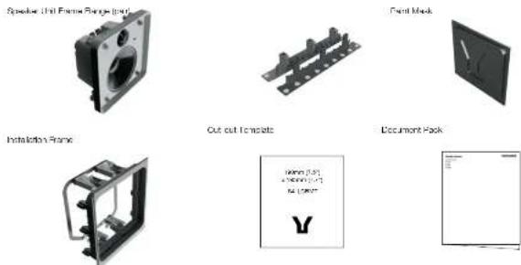
A typical carton contents is illustrated in Diagram 1.
Diagram 1
text_image
Speaker Unit Frame Range (r): Panel Mock Installation Frame Cut-out Template Document Rack2. Preparation
Before commencing any S4-LCR Series installation you must be sure that the wall positions chosen are free of obstructions such as pipe work, ducting or wiring that might interfere with the installation. Stud-finding, pipe detecting and wire detecting tools can help map the wall construction and identify any potential obstructions.
2.1 S4-LCR Series Module Selection
The modular format of the S4-LCR Series enables a variety of arrangements of mid/tweeter (S4-LCRMT) and bass modules (S4-LCR65W) to be installed to suit different front channel requirements. The S4-LCR Series modular format also enables in-wall front channel speakers to be installed around the constraints that may result from dry-wall slud spacing. Three typical installation examples are illustrated below.
Left and right speakers can be created from an S4-LCRMT module combines with either one, or in larger listening spaces, twin S4-LCR65W modules. Centre channel speakers always require a single S4-LCRMT and twin S4-LCR65W modules.
2.2 S4-LCR Series Installation Examples
Installation Example A:

natural_image
Pure electrical circuit lines without any symbols- Left, centre and right speakers installed with 42" TV in a dry wall with simple 400 mm (16") stud spacing.
- Each Left and Right speakers comprises one S4-LCRMT and one S4-LCR65W consolidated in a common wall cut-out. S4-LCRMT upper frame flange and S4-LCR65W lower frame flange fitted.
- Centre speaker comprises one S4-LCRMT and two S4-LCR65W mounted in separate wall cut-outs. All frame flanges fitted.
Installation Example B:
natural_image
Interior layout diagram of a TV setup with speakers and a large screen (no text or symbols)- Left, centre and right speakers installed with 42" TV in a dry wall with modified 400 mm (16") stud spacing. Stud arrangement configured to create centre speaker aperture.
- Each Left and Right speakers comprises one S4-LCRMT and one S4-LCR65W consolidated in a common wall cut-out. S4-LCRMT upper frame flange and S4-LCR65W lower frame flange fitted.
- Centre speaker comprises one S4-LCRMT and two S4-LCR65W consolidated in a common wall cut-out. S4-LCR65W left and right frame flanges fitted.
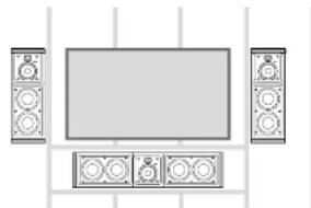
Installation Example C:

natural_image
Top-down view of a large rectangular table with four side-mounted circular speakers (no text or symbols visible)Left centre and right speakers installed with 65" TV in a dry wall with simple 400 mm (16") stud spacing.
- Each left and Right speaker comprises one S4-LCRMT and two S4-LCR65W consolidated in a common wall cut-out. S4-LCR65W lower and upper frame flanges fitted.
- Centre speaker comprises one S4-LCRMT and two S4-LCR65W mounted in separate wall cut-outs. All frame flanges fitted.
2.3 S4-LCR Series Cut-out and Clearance Dimensions
The S4-LCRMT and S4-LCR85W modules require specific wall cut-out dimensions but have common mounting depth space and drywell (plasterboard) thickness constraints. These dimensions are illustrated in Diagrams 2 and 3 and listed in the table. Diagrams 3A to 3C also illustrate an S4-LCR module with Frame Flanges fitted and removed, and an S4-LCRMT and S4-LCR85W module consolidated.
Diagram 2
S4-LCR Series wall cut-out dimensions

text_image
190 mm (7.2 m) Single S4-LCRMT module. 275 mm (85 m) 130 mm (7.41 m) Single S4-LCR6W module. 373 mm (3.47 m) 190 mm (7.2 m) Single S4-LCRMT module consolidated with single S4- LCR6W module. 565 mm (2.2% m) 130 mm (7.3 m) Single S4-LCRMT module consolidated with fin S4- LCR6W modules. 91° mm (5.6 m) Note: All wall cut-outs are shown in portalt orientation for left/right channel use, with upper/flower frame flanges. For centre channel use, with left/right frame flanges, the wall cut-out must be rotated 90° (landscape format).Module Cut-out Size Min Clear Depth Drywall (Plasterboard) thickness
| S4-LCRMT 190 x 213 mm 90.25 mm X - 32 mm max / 8 mm min | |||
| (7% x 6% in) (3) | % in) (1) | % in max / 0% in min) | |
| S4-LCR65W 190 x 373 mm 90.25 mm X - 32 mm max / 8 mm min | |||
| (7% x 14% in) (3) | % in) (1) | % in max / 0% in min) | |
| S4-LCRMT 190 x 563 mm 90.25 mm X - 32 mm max / 8 mm min | |||
| + 1 x S4LCR65W (7) | % in x 22% in) (3) | % in) (1) | % in max / 0% in min) |
| S4-LCRMT 190 x 914 mm 90.25 mm X - 32 mm max / 8 mm min | |||
| + 2 x S4LCR65W (7) | % in x 36 in) (3) | % in) (1) | % in max / 0% in min) |
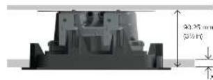
Diagrams 3A - 3C
3A. S4-LCR Series minimum clear depth and dry-wall thickness
3B. S4-LCRMT Installation Frame with and without Frame Flanges
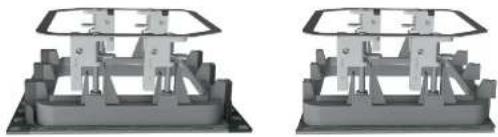
natural_image
Two identical mechanical assembly diagrams showing structural components (no text or symbols)3C. S4-LCRMT and S4-LCR65W Installation Frames consolidated with Frame Flanges

natural_image
Mechanical assembly frame with three vertical supports and a horizontal rail (no text or symbols visible)2.4 Back Boxes
In-wall speakers are often installed with back boxes in order to reduce sound transmission into adjacent rooms or to satisfy any local statutory building regulations. S4-LCRMT modules however incorporate an integrated back box so none is needed on installation.
S4-LCR65W modules do not incorporate a back box and if back boxes are to be used they must be installed within the walls before the drywall (plasterboard) is afted to the studs. Alternatively, the existing drywall (plasterboard) around each speaker installation position may be removed to enable a back box to be installed. The drywall (plasterboard) should be reinstated following back box installation.
Dynaudio does not supply back boxes suitable for S4-LCR65W modules however, back boxes from alternative manufacturers may be used, or back boxes may be constructed on site. In either case, each S4-LCR65W module requires a 30 Litre (1.1 ft ^2 ) minimum back box volume in order to reach its full audio performance potential.
Check with local building regulations for fire safety. In some areas it is required to have a fire-rated back box as a fire safety barrier. Ensure that the surrounding materials meet the flammability Class 5VA. A fire rated metal back box must have a minimum uncoated thickness of 1.35 mm.
3. Speaker Positions
S4-LCR Series modules are designed specifically for front and centre channel applications in multi-channel audio visual installations. Position guidelines and diagrams are covered in the following paragraphs and illustrated in Diagram 4.
The left and right speakers should be located either side of the screen. The centre channel speaker should be located centrally above or below the screen, ideally less than 0.25 m (10 in) away.
In the case of acoustically transparent screens the centre channel speaker should be located centrally behind the screen.
Note: The nature of the installation of custom install speakers means that it is sometimes impractical to locate them in ecoustically optimal positions. Compromise is often more likely to be necessary in multi-channel installations where positions have to be found for multiple speakers. In these circumstances it is preferable to favour the position of the front and centre channel speakers over that of the surround channel speakers.
Diagram 4
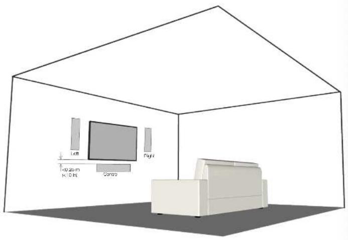
natural_image
Interior layout diagram of a modern living room with TV, sofa, and wall-mounted appliances (no text or symbols)4. Connections and Mode Settings
S4-LCR Series systems can be connected in either passive or active mode. Diagrams 5 to 8 illustrate passive and active connection of systems comprising both one and two S4-LCR65W modules.
4.1 Passive Mode
- In passive mode, the S4-LCRMT and S4-LCP85W modules employed for each channel are connected in parallel to a single power amplifier channel.
- The mode selection switch on the rear of the S4-LCRMT module should be switched to "1W" if one S4-LCR65W is used (per S4-LCRMT) and switched to "2W" if two are used. Ensure that the mode selection switch position is correct before use.
- The two mode selection jumpers on the crossover PCB of each S4-LCR65W module should be located in the U1 position. The mode selection jumpers can be accessed by lifting the crossover assembly from the back of the S4-LCR65W module. This is achieved by removing the four screws identified in Diagram 5.
Note: S4-LCR65W modules are initially supplied with their jumpers in the J1 position. Jumper position should however always be confirmed visually before S4-LCR65W modules are installed.
Diagram 5
S4-LCRMT and single S4-LCR65W connection in passive mode.

text_image
Onshore assembly switches Connect to another + - IMS swi theSwitch in 19 position, jumps in .81 position

IMPORTANT Ensure that the mode selection switch position is correct. Damage may result if the switch position is incorrect.
Diagram 6: S4-LCRMT and twin S4-LCR65W connection in passive mode.
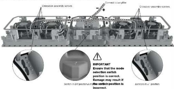
text_image
Crossover assembly screws Dermaed to amplifier Crossover assembly screws IMPORTANT Ensure that the mode selection switch position is correct. Damage may result if the switch position is incorrect. Switch in 24V positions, then the switch position is incorrect. Jumors in 3' position4.2 Active Mode
- In active mode, each S4-LCRMT and single or multiple S4-LCR65W module employed for each channel is connected separately to a power amplifier channel.
- The mode selection switches on the rear of each S4-LCP65W module or modules should be switched to "BYP" (bypass). Ensure that the mode selection switch position is correct before use.
- The two mode selection jumpers on the crossover PCB of each S4-LCR65W module should be located in the J2 position. The mode selection jumpers can be accessed by lifting the crossover PCB module from the back of the S4-LCR65W module. This is achieved by removing the four screws identified in Diagram 7.
- The power amplifier channel driving each S4-LCRMT and S4-LCR65W modules must be driven via active filters. The recommended filter characteristics are tabulated below.
Filter \4-LCR65W \4-LCRMT
Type Low pass High pass
Frequency 300 Hz 500 Hz
Slope 12 dB/octave 12 dB/octave
Q0.711.0
Gain 0 dB (see note)
0 dB
Note: Where a S4-LCRMT module is used with a single S4-LCR65W module, the S4-LCR65W gain should be reduced by -6 dB.
Diagram 7: S4-LCRMT and single S4-LCR65W connection in active mode.
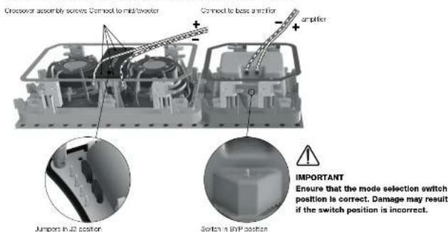
text_image
Crossover assembly solves Connect to mid/motor Connect to base anchor ampifier Jumpers in 2D position Switch in BYP position IMPORTANT Ensure that the mode selection switch position is correct. Damage may result if the switch position is incorrect.Diagram 8: S4-LCRMT and twin S4-LCR65W connection in active mode.

text_image
Connect to base spring Connect to inducts and hot Crossover assembly Connect to base spring IMPORTANT Ensure that the mode selection switch position is correct. Damage may result if the switch position is incorrect.5. Speaker Installation
To install S4-LCR Series modules, proceed as described in the following paragraphs and Diagram 9:
Note: Diagram 9 illustrates the installation of a S4-LCRMT module. S4-LCR65W and multiple module installation is carried out in the same manner.
- Having selected the installation positions and checked for the presence of studs (joists), pipe work, ducts or cables, mark cut-lines on the wall using the supplied template or templates. Check that the dimensions of the cut-line are correct.
Note: In order to reduce the possibility of audible wall vibration, it may be prudent to apply a bead of adhesive mastic between the wall studs and the drywall (plasterboard) in the vicinity of wall speakers.
① Use an appropriate tool to cut along the cut-line to create a cut-out in the wall. Trial fit the installation Frame or frames in the cut-out to check clearances.
② With the cut-out checked, the installation Frame or frames can be installed. If frame flanges are required these should be fitted at this stage. If the installation comprises multiple S4-LCR modules, all installation frames should be fitted at the same time.
3 To install an Installation Frame, insert the frame into the wall cut-out and while holding it against the wall with one hand. Use your other hand to turn four yellow securing clamps outwards and slide them down securely against the inner surface of the drywall (plasterboard).
Note: if speaker cables are not already installed it should be done at this stage. It is possible that access will be required through the opposite side of the wall to route the cables. Use low resistance speaker cable with clear polarity masking on its insulation. Low resistance is especially important if the length of cable from amplifier to speaker exceeds 5 m. Your local Dynaudio retailer or distributor will be able to offer advice on speaker cable selection if required.
- Pull the speaker cable through the appropriate Installation Frame and wall cut-out. The length of free cable should be sufficient to allow the Speaker Unit to be held in one hand while connecting the cable to the speaker terminals with the other hand.
④ The speaker cable can now be connected to the Speaker Unit. Strip 15 mm insulation from the cable (if necessary), twist the wire strands and insert the stripped ends into the speaker spring terminals. Ensure that the positive conductor is connected to the red speaker terminal and the negative conductor is connected to the black speaker terminal.
⑤ With the Speaker Unit connected to the speaker cable it can be inserted into the Installation Frame. Turn the locking tabs on the front surface of the Speaker Unit fully clockwise (aligned with the lock icons) and insert it in the Installation Frame. Push gently around each locking tab until a click is heard. The Speaker Unit will then be secured in the Installation Frame.
Note: Take care that the cable is positioned in such a way that it will not get trapped as the Speaker Unit is secured into the installation. Frame and is not touching the Speaker Unit in such a manner that it is likely to result in audible vibrations.
Note: To remove a Speaker Unit from the Installation Frame turn the locking tabs 90" counter-clockwise. Take care to support the speaker as the locking tabs are turned.
Note: The high frequency total balance of S4-LCRMT modules can be adjusted to suit different installation environments. A tweter level switch located on the Speaker Unit front panel offers +2 dB and -1 dB options. The level adjustment operates from approximately 3 kHz upwards. The +2 dB option may be appropriate if, for example, carpets, soft furnishings and curtains dominate in the listening environment. The -1 dB option may be more suited to an environment where hard floors and glass predominate.
- With speaker units connected and secured into in installation frames, installation is completed by fitting grilles. Crilles are secured magnetically and require no more than placing into position.
Note: If the wall is to be painted following speaker installation, the supplied paint mask must be used to protect the speaker hardware from paint ingress. Speaker grilles should not be fitted during wall painting. They should be painted separately.
Diagram 9 illustrates the in-wall speaker installation procedure.
Diagram 9
①
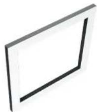
natural_image
Simple 3D rectangular frame with a black line on the left face, no text or symbols present.2
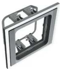
natural_image
3D rendering of a mechanical component with mounting brackets and a central cutaway view (no text or symbols)③
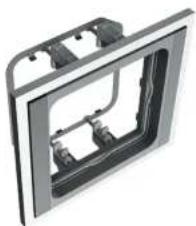
natural_image
3D rendering of a mechanical housing or enclosure with internal components (no text or symbols visible)4

natural_image
3D mechanical assembly diagram showing internal components and a spring mechanism (no text or symbols)5

natural_image
3D rendering of a speaker inside a square frame, showing internal components and mounting brackets (no text or symbols)Switch to adjust tweeter level
Push to click.
Four locations.
Rotate clockwise to lock.
Rotate counter-clockwise to release.
Specifications
S4-LCR Series
Data S4-LCRMT S4-LCR65W
| Type Two-way in-wall mid/tweeter module Twin-driver in-wall bass module | ||
| Drivers | Tweeter: 25 mm (1 in)Bass/mid: 100 mm (4 in) | 2 x 165 mm ( 6^1/2 in) |
| Frequency response 250 Hz - 20 kHz ±3 dB 35 Hz - 3 kHz ±3 dB | ||
| Impedance | 8 Ω nominal5 Ω minimum | 4 Ω nominal3.2 Ω minimum |
| Sensitivity 89±3 dB (250-20 kHz) 86±3 dB (40-250 Hz) | ||
| Rated power* 50 W 50 W | ||
| Long term power* 150 W 200 W | ||
| Tweeter level options +3 dB/0/-3 dB N/A | ||
| Dimensions (including flanges) | 235 x 213 mm 9^1/4 x 8^3/8 in | 395 x 213 mm 15^1/2 x 8^3/8 in |
| Depth | 90 mm 3^1/2 in | 90 mm 3^1/2 in |
| Cut-out dimensions | 190 x 213 mm 7^1/2 x 8^3/8 in | 190 x 373 mm 7^1/2 x 14^11/16 in |
| Grille material | Painted steel | Painted steel |
| Grille attachment | Magnetic | Magnetic |
| Grille finish | Paintable | Paintable |
| Certifications CE CE | ||
| Environmental | RoHS | RoHS |
* Power handling according to IEC268. Rated power is continuous power for 100 hours.
Grille dimensions
| System | 1 x S4-LCRMT | 1 x S4-LCR65W | 1 x S4-LCRMT1 x S4-LCR65W | 1 x S4-LCRMT2 x S4-LCR65W | Custom |
| Dimensions | 264 x 230 mm 10^3/_8 x 9 in | 424 x 230 mm 16^1/_16 x 9 in | 614 x 230 mm 24^3/_16 x 9 in | 985 x 230 mm 38^3/_4 x 9 in | 1319 x 230 mm 51^15/_16 x 9 in |
DYNAUDIO
Dynaudio A/S, 8660 Skanderborg, Denmark
www.dynaudio.com
EN - Item No. 307001017205 Rev K