PPX-2002-GPIB - Measuring instrument GW Instek - Free user manual and instructions
Find the device manual for free PPX-2002-GPIB GW Instek in PDF.

User questions about PPX-2002-GPIB GW Instek
0 question about this device. Answer the ones you know or ask your own.
Ask a new question about this device
Download the instructions for your Measuring instrument in PDF format for free! Find your manual PPX-2002-GPIB - GW Instek and take your electronic device back in hand. On this page are published all the documents necessary for the use of your device. PPX-2002-GPIB by GW Instek.
USER MANUAL PPX-2002-GPIB GW Instek
Programmable High Precision DC Power Supply
PPX Series
USER MANUAL
Rev. A
This manual contains proprietary information, which is protected by copyright. All rights are reserved. No part of this manual may be photocopied, reproduced or translated to another language without prior written consent of Good Will company.
The information in this manual was correct at the time of printing. However, Good Will continues to improve products and reserves the rights to change specification, equipment, and maintenance procedures at any time without notice.
Table of Contents
SAFETY INSTRUCTIONS 5
GETTING STARTED 8
PPX Series Overview 9
Appearance....12
Theory of Operation 20
OPERATION 30
Set Up....31
Menu Tree....40
Basic Operation 46
Sequence Test....74
MENU CONFIGURATION....107
Configuration Overview 108
Output....108
Measurement.... 112
EXT Control 115
TRIG Control....120
PWR On Config....126
Constant PWR 127
Temperature.... 130
Save/Recall 134
Interface 137
Utility.... 144
APP....152
Calibration 155
ANALOG CONTROL....156
Analog Remote Control Overview ..... 157
Remote Monitoring.... 173
COMMUNICATION INTERFACE 178
Interface Configuration 179
FAQ....208
APPENDIX....210
PPX Factory Default Settings...... 210
PPX Specifications 213
PPX Dimensions 218
Declaration of Conformity 219
INDEX 220
SAFETY INSTRUCTIONS
This chapter contains important safety instructions that you must follow during operation and storage. Read the following before any operation to insure your safety and to keep the instrument in the best possible condition.
Safety Symbols
These safety symbols may appear in this manual or on the instrument.

WARNING
Warning: Identifies conditions or practices that could result in injury or loss of life.

CAUTION
Caution: Identifies conditions or practices that could result in damage to the PPX or to other properties.

DANGER High Voltage

Attention Refer to the Manual

Protective Conductor Terminal

Earth (ground) Terminal

Do not dispose electronic equipment as unsorted municipal waste. Please use a separate collection facility or contact the supplier from which this instrument was purchased.
Safety Guidelines
General Guideline

CAUTION
- Do not place any heavy object on the PPX.
- Avoid severe impact or rough handling that leads to damaging the PPX.
- Do not discharge static electricity to the PPX.
- Use only mating connectors, not bare wires, for the terminals.
- Do not disassemble the PPX unless you are qualified.
Power Supply
- AC Input Voltage: 100Vac/120Vac/220Vac/240Vac, 50Hz/60Hz, single phase

CAUTION
• Frequency: 47Hz to 63Hz
- Before connecting the power plug to an AC line outlet, make sure the voltage selector switches of the bottom panel in the correct position.

WARNING
- Disconnect power cord and test leads before replacing fuse.
• The fuse specification is as following:
| FUSE | LINE |
| 250VT3.15A | 100V~120V~ |
| 250VT1.6A | 220V~240V~ |
- To avoid electrical shock connect the protective grounding conductor of the AC power cord to an earth ground.
| Cleaning the PPX | · Disconnect the power cord before cleaning.· Use a soft cloth dampened in a solution of mild detergent and water. Do not spray any liquid.· Do not use chemicals containing harsh material such as benzene, toluene, xylene, and acetone. |
| Operation Environment | · Location: Indoor, no direct sunlight, dust free, almost non-conductive pollution (Note below)· Relative Humidity: 20%~80% (no condensation)· Altitude: < 2000m· Temperature: 0°C to 40°C(Pollution Degree) EN61010-1:2010 specifies the pollution degrees and their requirements as follows. The PPX falls under degree 2.Pollution refers to “addition of foreign matter, solid, liquid, or gaseous (ionized gases), that may produce a reduction of dielectric strength or surface resistivity”.· Pollution degree 1: No pollution or only dry, non-conductive pollution occurs. The pollution has no influence.· Pollution degree 2: Normally only non-conductive pollution occurs. Occasionally, however, a temporary conductivity caused by condensation must be expected.· Pollution degree 3: Conductive pollution occurs, or dry, non-conductive pollution occurs which becomes conductive due to condensation which is expected. In such conditions, equipment is normally protected against exposure to direct sunlight, precipitation, and full wind pressure, but neither temperature nor humidity is controlled. |
| Storage environment | · Location: Indoor· Temperature: -20°C to 70°C· Relative Humidity: 20 to 85%(no condensation) |
Disposal | Do not dispose this instrument as unsorted municipal waste. Please use a separate collection facility or contact the supplier from which this instrument was purchased. Please make sure discarded electrical waste is properly recycled to reduce environmental impact. |

ETTING STARTED
This chapter describes the power supply in a nutshell, including its main features and front / rear panel introduction. After going through the overview, please read the theory of operation to become familiar with the operating modes, protection modes and other safety considerations.

text_image
GP-ISTEM 20.000 2.0000A Control buttons Reset Reset Reset Reset Control buttons Reset Control buttons Control buttons Control buttons Control buttons Control buttons Control buttons Control buttons Control buttons Control buttons Control buttons Control buttons Control buttons Control buttons Control buttons Control buttons Control buttons Control buttons Control buttons Control buttons Control buttons Control buttons Control buttons Control buttons Control buttons Control buttons Control buttons Control buttons Control buttons Control buttons Control buttons Control buttons Control buttons Control buttons Control buttonsPPX Series Overview 9
Series lineup 9
Main Features 9
Accessories....10
Appearance....12
Front Panel....12
Display Area....16
Rear Panel....18
Theory of Operation 20
Operating Description ....20
CC and CV Mode....21
Slew Rate 22
Bleeder Control 23
Alarms....24
Considerations 25
Grounding....28
PPX Series Overview
Series lineup
The PPX series consists of 6 models, covering a number of different current, voltage and power capacities:
| Model name | Operation Voltage | Operation Current | Rated Power |
| PPX-1005 | 0-10V | 0-5A | 50W |
| PPX-2002 | 0-20V | 0-2A | 40W |
| PPX-2005 | 0-20V | 0-5A | 100W |
| PPX-3601 | 0-36V | 0-1A | 36W |
| PPX-3603 | 0-36V | 0-3A | 108W |
| PPX-10H01 | 0-100V | 0-1A | 100W |
Main Features
Features
- 2.4" TFT-LCD Panel.
- Preset memory function.
• Output ON/OFF delay function.
• CV, CC priority start function. (prevents overshoot with output ON)
- Adjustable voltage and current slew rates.
- Bleeder circuit ON/OFF setting. (to prevent over-discharging of batteries)
• OVP, OCP, AC Alarm and OTP protection.
• Supports test sequence.
- Web server monitoring and control. (The function is activated when connecting to LAN Interface)
• Analog monitor output.
| Remote sensing to compensate for voltage drop in load leads.Support K type thermocouple temperature measurement.With 4 measuring currents and Manual / Auto shift function. | |
| Interface | Built-in USB, RS-232/485 and LAN interface.External analog control function.Optional GPIB interface. |
Accessories
Before using the PPX power supply unit, check the package contents to make sure all the standard accessories are included.
| Standard Accessories | Part number | Description | Qty. |
| GTL-104A | Test leads for PPX-1005/PPX-2005/PPX-3603 (Binding Posts Terminal), 1m, 10A | 1 | |
| GTL-105A | Test leads for PPX-2002/PPX-3601, 1m, 3A | 1 | |
| Short Bar (Binding Posts Terminal) | 1 | ||
| GTL-204A | Test leads for PPX-1005/PPX-2005/PPX-3603 (European Type Jack Terminal), 1m, 10A | 1 | |
| GTL-203A | Test leads for PPX-2002/PPX-3601/PPX-10H01 (European Type Jack Terminal), 1m, 3A | 1 | |
| GTL-201A | Ground lead for European Type Jack Terminal | 1 | |
| Power Cord | 1 |
| Optional Accessories | Part number | Description |
| GRA-441-J | Rack for PPX (JIS) | |
| GRA-441-E | Rack for PPX (EIA) | |
| GTL-205A | Temperature probe adaptor with thermocouple K type | |
| GTL-246 | USB Cable (USB 2.0 Type A- Type B Cable, 4P) | |
| GTL-258 | GPIB Cable, 2000mm | |
| GTL-259 | RS232 cable with DB9 connector to RJ45 | |
| GTL-260 | RS485 cable with DB9 connector to RJ45 | |
| GTL-262 | RS485 slave cable | |
| Factory Installed Options | Part number | Description |
| Option 1 | GPIB interface |
Appearance
Front Panel
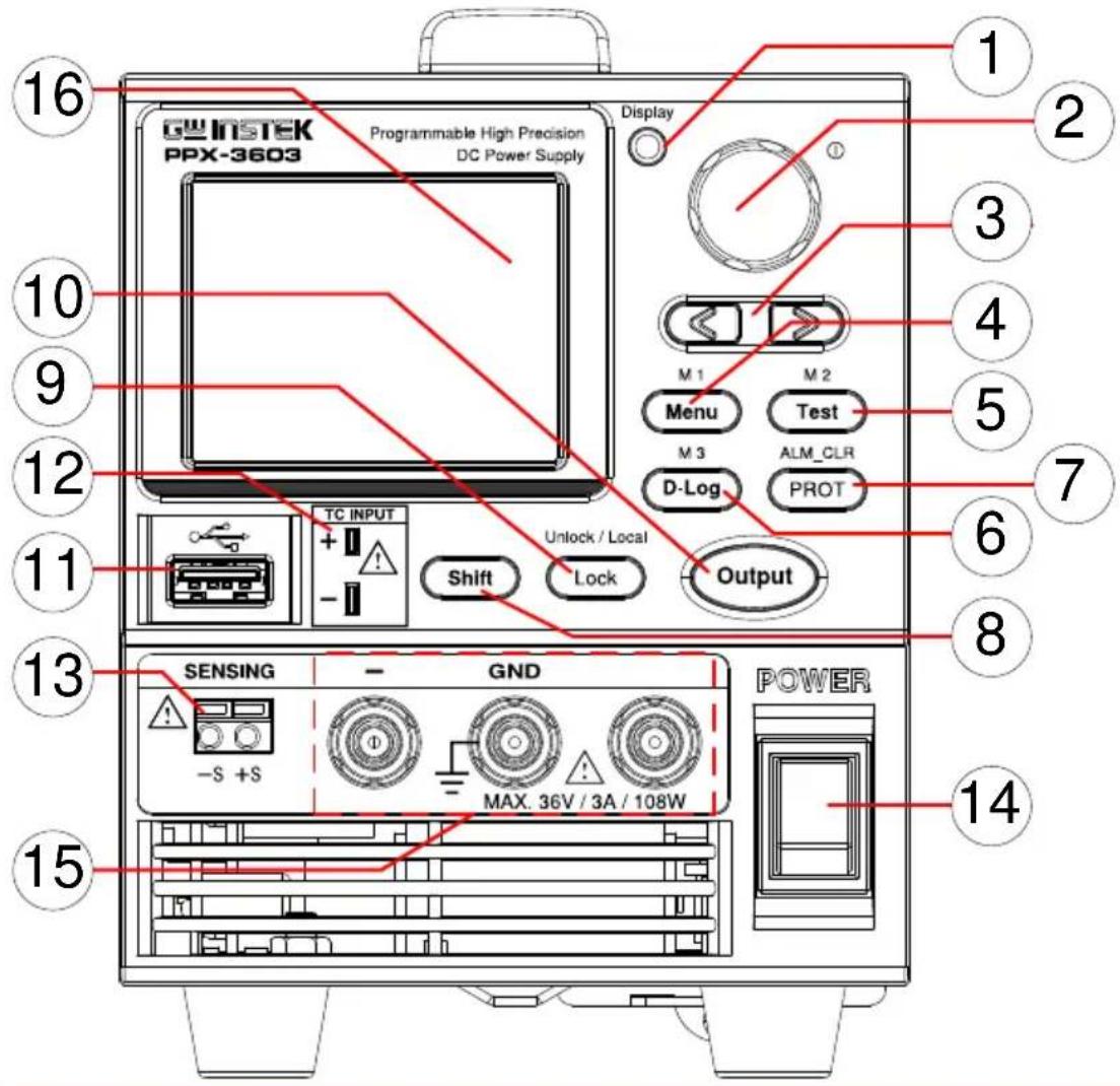
text_image
GW INSTEK PPX-3603 Programmable High Precision DC Power Supply Display M 1 Menu M 2 Test ALM_CLR D-Log PROT Output TC INPUT + - Unlock / Local Shift Lock 16 10 9 12 11 13 SENSING - GND - S +S MAX. 36V / 3A / 108W POWER 14 15 1 2 3 4 5 6 7 8- Display Button

Used to switch among 4 different display modes.
- Knob Key
Used to navigate menu, and to configure or confirm voltage/current/time values, among others. Also, the indicator on the upper-right corner shows current state and power mode.
- Left/Right Arrow Keys
Used to select a parameter number in the Function settings. Also the left arrow key can be used as backspace.
- Menu Button
Used to enter the Menu page. Refer to page 108 for detail.
M1 Button
(+Shift) Used to recall the M1 setup.
- Test Button
Used to run customized test sequence. Refer to page 74 for detail.
M2 Button
(+Shift) Used to recall the M2 setup.
- D-Log Button
Used to run data log function. Refer to page 71 for detail.
M3 Button
(+Shift) Used to recall the M3 setup.
- PROT Button
Used to set OVP, OCP and UVL protecting functions. Refer to page 47 for details.
ALM_CLR Button

(+Shift) Used to release protection functions that have been activated. The tripped protection alarms include the following: OVP Alarm, OCP Alarm, OTP Alarm, AC Alarm, Sense Alarm, WDOG Alarm, Ah CAP Alarm, Wh CAP Alarm, TEMP Short Alarm, TEMP Monitor Alarm.
- Shift Button

Used to enable the functions that are written in blue characters above certain buttons.
9. Lock Button
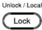
Unlock/Local Button
Used to lock all front panel buttons other than the Output Button. Refer to page 60 for detail.
(+Shift) Used to unlock the front panel buttons or it switches to local mode.
- Output Button

Used to turn the output on or off.
- USB A Port

USB A port for data transfer, loading test scripts and firmware update.
- TC Input

Terminal to connect the K type thermocouple cable for temperature measurement. Refer to page 66 for detail.
- Sensing Terminal
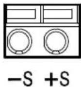
Terminal to connect the sensing cables, which compensate voltage drop occurred in load leads.
- Power Switch

Used to turn the power on/off.
- Output terminal

text_image
- GND + MAX. 100V / 1A / 100WDC output terminal for PPX is European Type Jack Terminal.
PPX-10H01 the max. output is 100V/1A/100W

text_image
- GND + MAX. 10V / 5A / 50WDC output terminal for PPX is Binding Posts Terminal or European Type Jack Terminal.
PPX-1005 the max. output is 10V/5A/50W
text_image
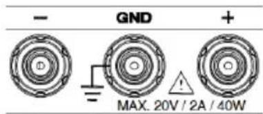
- GND + MAX. 20V / 2A / 40WDC output terminal for PPX is Binding Posts Terminal or European Type Jack Terminal.
PPX-2002 the max. output is 20V/2A/40W
text_image
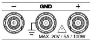
- GND + MAX. 20V / 5A / 100WDC output terminal for PPX is Binding Posts Terminal or European Type Jack Terminal.
PPX-2005 the max. output is 20V/5A/100W

text_image
- GND + MAX. 36V / 1A / 36WDC output terminal for PPX is Binding Posts Terminal or European Type Jack Terminal.
PPX-3601 the max. output is 36V/1A/36W
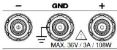
text_image
- GND + MAX. 36V / 3A / 108WDC output terminal for PPX is Binding Posts Terminal or European Type Jack Terminal.
PPX-3603 the max. output is 36V/3A/108W
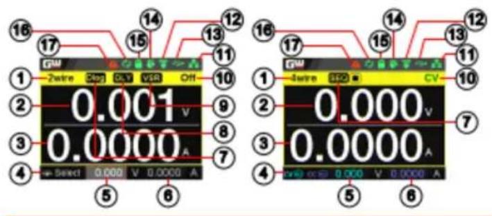
16 Display Area The display area shows set values, output values and parameter settings.
Display Area
text_image
16 17 14 13 12 11 10 9 8 7 6 5 1 2 3 4 Select 0.000 V 0.000 A 16 17 15 14 13 12 11 10 0.001 V 0.000 A 0.000 V 0.000 A 1 2 3 4 0.000 V 0.000 A 0.000 V 0.000 A CV 7 6- 2Wire/4Wire 2-wire or 4-wire indicator.
- Voltage Meter Displays the voltage.
- Current Meter Displays the current.
- V/A Set Guidance The scrolling symbol indicates to select between V and A set via scrolling knob key.
| 8. | DLY Icon | When Output On/Off Dly is enabled, the icon will be shown accordingly. Note that when SEQ appears, the icon will be faded out. |
| 9. | VSR/ISR Icon | When CV/CC Slew Rate Priority (CVLS/CCLS) is activated, the icon will be shown. Note that when SEQ appears, the icon will be faded out. |
| 10. | CC/CV/UR indicator | It shows when constant voltage or constant current mode is ongoing. However, when output is unregulated, which means neither in CV mode nor CC mode, it shows UR instead. If it is not under power output, it simply shows Off. |
| 11. | LAN Indicator | When PPX series connects to LAN network, the icon will be shown. |
| 12. | Remote Control Indicator | When remote control (USB/LAN/GPIB, UART) is underway, the icon will be shown. |
| 13. | USB Indicator | When USB disk is inserted into the front panel of PPX series, the icon will be shown. |
| 14. | External Output Indicator | When external output enable is turned On, the icon will be shown. |
| 15. | Lock Indicator | When the lock mode is activated, the icon will be shown. |
| 16. | Communication Monitor Indicator | When communication monitor is enabled, the icon will be shown. |
| 17. | Error Indicator | When error occurs from command of remote control, the icon will be shown. |
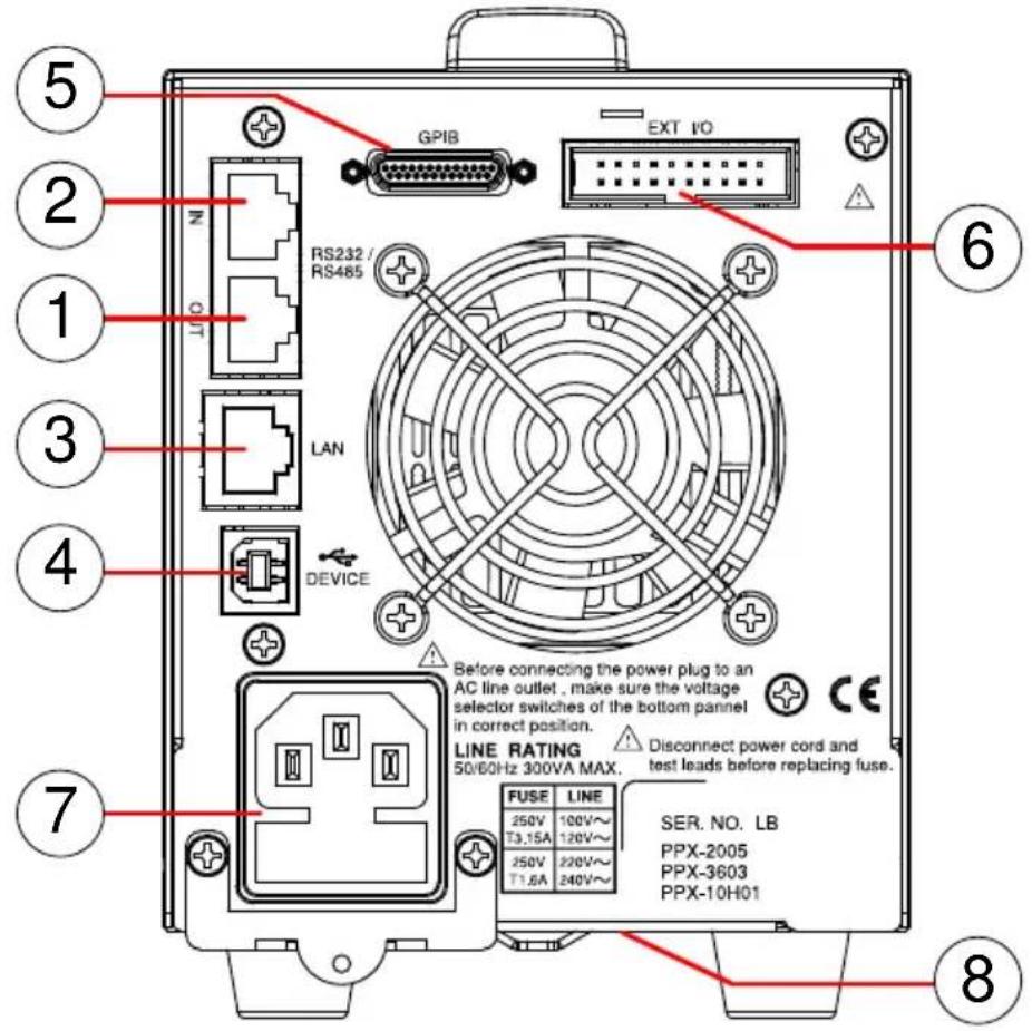
Rear Panel
text_image
5 2 1 3 4 7 GPIB EXT I/O RS232 / RS465 LAN DEVICE Before connecting the power plug to an AC line outlet, make sure the voltage selector switches of the bottom panel in correct position. LINE RATING 50/60Hz 300VA MAX. Disconnect power cord and test leads before replacing fuse. FUSE LINE 250V 100V~ T3.15A 120V~ 250V 220V~ T1.6A 240V~ SER. NO. LB PPX-2005 PPX-3603 PPX-10H01- Remote-OUT RJ-45 connector that is used to daisy chain power supplies with the Remote-IN port to form a communication bus.
- Remote-IN Two different types of cables can be used for RS232 or RS485-based remote control. PSU-232: RS232 cable with DB9 connector kit. PSU-485: RS485 cable with DB9 connector kit.
- LAN Ethernet port for controlling the PPX remotely
-
USB USB port for controlling the PPX remotely.
-
GPIB GPIB connector for units equipped with IEEE programming option. (Factory Installed Options)
-
EXT I/O External analog remote control connector.
-
Line Voltage AC inlet. Input
-
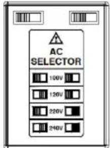
AC Select Switch
text_image
AC SELECTOR 100V 120V 220V 240VThe AC selector is located at the bottom side of the unit.
Switch Voltage to 100V, 120V, 220V or 240V.
Theory of Operation
The theory of operation chapter describes the basic principles of operation, protection modes and important considerations that must be taken into account before use.
Operating Description
Background
The PPX power supplies are regulated DC power supplies with a stable voltage and current output. These operate within a switch automatically between constant voltage and constant current according to changes in the load.

Suitable supply cord set for use with the equipment:
- Mains plug: shall be national approval
- Mains connector: C13 type
-
Cable:
-
Length of power supply cord: less than 3m
- Cross-section of conductors: at least 0.75mm^2
- Cord type: shall meet the requirements of IEC 60227 or IEC 60245 (e.g.: H05VV-F, H05RN-F)

Caution
If the equipment is used in a manner not specified by the manufacturer, the protection provided by the equipment may be impaired.
CC and CV Mode
CC and CV mode Description
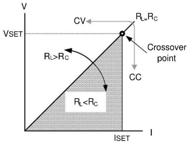
When the power supply is operating in constant current mode (CC) a constant current will be supplied to the load. When in constant current mode the voltage output can vary, whilst the current remains constant. When the load resistance increases to the point where the set current limit ( I_SET ) can no longer be sustained the power supply switches to CV mode. The point where the power supply switches modes is the crossover point.
When the power supply is operating in CV mode, a constant voltage will be supplied to the load, whilst the current will vary as the load varies. At the point that the load resistance is too low to maintain a constant voltage, the power supply will switch to CC mode and maintain the set current limit.
The conditions that determine whether the power supply operates in CC or CV ( V_SET ), the load resistance ( R_L ) and the critical resistance ( R_C ). The critical resistance is determined by V_SET/I_SET . The power supply will operate in CV mode when the load resistance is greater than the critical resistance. This means that the voltage output will be equal to the V_SET voltage but the current will be less than I_SET . If the load resistance is reduced to the point that the current output reaches the I_SET level, the power supply switches to CC mode.
Conversely the power supply will operate in CC mode when the load resistance is less than the critical resistance. In CC mode the current output is equal to I_SET and the voltage output is less than V_SET .
text_image
V CV R_L=R_C VSET R_L>R_C Crossover point CC R_LSlew Rate
Theory
The PPX has selectable slew rates for CC and CV mode. This gives the PPX power supply the ability to limit the current/voltage draw of the power supply. Slew rate settings are divided into High Speed Priority and Slew Rate Priority. High speed priority mode will use the fastest slew rate for the instrument. Slew Rate Priority mode allows for user adjustable slew rates for CC or CV mode. The rising and falling slew rate can be set independently. text_image
High Speed Priority mode Slew rate = EnabledBleeder Control
Background The PPX DC power supplies employ a bleed resistor in parallel with the output terminals. text_image
PPX Bleed resistor LoadAlarms
The PPX power supplies have a number of protection features. When one of the protection alarms is set, the ALM icon on the display will be lit. For details on how to set the protection modes, please see page 47.OVP
Over voltage protection (OVP) prevents a high voltage from damaging the load. This alarm can be set by the user.OCP
Over current protection prevents high current from damaging the load. This alarm can be set by the user.UVL
Under voltage limit. This function sets a minimum voltage setting level for the output. It can be set by the user.OTP
Over temperature protection protect the instrument from overheatingAC ALARM
When AC input voltage or frequency is abnormal or beyond the AC power range under operation, the alarm will be generated.SENSE ALARM
This alarm function is activated when real output voltage is larger than sense output voltage.Alarm output
Alarms are output via the analog control connector. The alarm output is an isolated open-collector photo coupler output.Considerations
The following situations should be taken into consideration when using the power supply.| Inrush current | When the power supply switch is first turned on, an inrush current is generated. Ensure there is enough power available for the power supply when first turned on, especially if a number of units are turned on at the same time. |
| Caution | Cycling the power on and off quickly can cause the inrush current limiting circuit to fail as well as reduce the working life of the input fuse and power switch. |
| Pulsed or Peaked loads | When the load has current peaks or is pulsed, it is possible for the maximum current to exceed the mean current value. The PPX power supply ammeter only indicates mean current values, which means for pulsed current loads, the actual current can exceed the indicated value. For pulsed loads, the current limit must be increased, or a power supply with a greater capacity must be chosen. As shown below, a pulsed load may exceed the current limit and the indicated current on the power supply ammeter. |
natural_image
Pure electrical circuit lines without any symbolstext_image
PPX RD Eo Load IR Output Current + - IRtext_image
PPX Diode LoadCAUTION
Ensure the reverse withstand voltage of the diode is able to withstand 2 times the rated output voltage of the power supply and the forward current capacity can withstand 3 to 10 times the rated output current of the power supply. Ensure the diode is able to withstand the heat generated in the following scenarios. When the diode is used to limit reverse voltage, remote sensing cannot be used.Grounding
The output terminals of the PPX power supplies are isolated with respect to the protective grounding terminal. The insulation capacity of the load, the load cables and other connected devices must be taken into consideration when connected to the protective ground or when floating.Floating
As the output terminals are floating, the load and all load cables must have an insulation capacity that is greater than the isolation voltage of the power supply. flowchart
graph LR
    A["Ext-V\nExt-R"] --> B["Analog connector"]
    B --> C["PPX"]
    C --> D["Load"]
    style A fill:#f9f,stroke:#333
    style B fill:#ccf,stroke:#333
    style C fill:#cfc,stroke:#333
    style D fill:#fcc,stroke:#333
    note right of C: (----) Insulation capacity ≥ isolation voltage of power supply
WARNING
If the insulation capacity of the load and load cables are not greater than the isolation voltage of the power supply, electric shock may occur. Grounded output terminal If the positive or negative terminal is connected to the protective ground terminal, the insulation capacity needed for the load and load cables is greatly reduced. The insulation capacity only needs to be greater than the maximum output voltage of the power supply with respect to ground. flowchart
graph LR
    A["Ext-V\nExt-R"] --> B["Analog connector"]
    B --> C["PPX"]
    C --> D["Load"]
    C --> E["Measurement feedback loop"]
    E --> C
PERATION
Set Up....31
Power Up....31 Wire Gauge Considerations 32 Output Terminals....33 Connection with the front panel output terminal ....33 Using the Rack Mount Kit 34 How to Use the Instrument 34 Reset to Factory Default Settings....38 View System Version and Build Date 39Menu Tree....40
Menu Page - 1....41 Menu Page - 2......42 Menu Page - 3......43 D-Log....44 PROT....44 TEST 45Basic Operation 46
Setting OVP/OCP/UVL Levels....47 Set to C.V. Priority Mode ....51 Set to C.C. Priority Mode 55 Display Modes ....59 Panel Lock....60 Save Setup 61 Recall Setup....62 Remote Sensing....64 Temperature....66 Data Logger....71Sequence Test 74
Sequence Script File Format 75 Sequence Script Settings 75 Sequence Step Edit Settings....77 Setting Sequence Script Configurations 82 Run Sequence Script....94 Load Sequence Script....98 Save Sequence Script....101Set Up
Power Up
Background
Make sure that the power source is shut off. Use the AC power cable supplied with the product.Steps
1. Connect the power cord to the rear panel socket. natural_image
Pure mechanical diagram showing a component with a housing and shaft, without any text or symbols| Background | Before connecting the output terminals to a load, the wire gauge of the cables should be considered. It is essential that the current capacity of the load cables is adequate. The rating of the cables must equal or exceed the maximum current rated output of the instrument. | ||
| Recommended wire gauge | Wire Gauge | Nominal Cross Section | Maximum Current |
| 28 | 0.10 | 3 | |
| 26 | 0.15 | 4 | |
| 24 | 0.25 | 5 | |
| 22 | 0.35 | 7 | |
| 20 | 0.55 | 9 | |
| 18 | 1 | 12 | |
| The maximum temperature rise can only be 60 degrees above the ambient temperature. The ambient temperature must be less than 30 degrees. | |||
Output Terminals
Background
Before connecting the output terminals to the load, first consider whether voltage sense will be used, the gauge of the cable wiring and the withstand voltage of the cables and load.WARNING
Dangerous voltages. Ensure that the power to the instrument is disabled before handling the power supply output terminals. Failing to do so may lead to electric shock.Connection with the front panel output terminal
Steps
1. Turn the power switch off. text_image
POWERUsing the Rack Mount Kit
Background
The PPX series has an optional Rack Mount Kit (GW Instek part number: GRA-441-J [JIS], GRA-441-E [EIA]) that can be used to hold up to 4 PPX units into rack.GRA-441-E [EIA] Rack mount diagram
natural_image
Front view diagram of a rack-mounted server unit with multiple panels and control knobs (no text or labels visible)GRA-441-J [JIS] Rack mount diagram
natural_image
Front view diagram of a rack-mounted server unit with multiple front panels and control knobs (no text or labels)How to Use the Instrument
Background
The PPX power supplies generally use the knob key and arrow keys to enter each page and setting, to return to previous page, to edit numerical values or to confirm settings. The following section will explain some of these concepts in detail.Example 1
Use the knob key and arrow keys to set a voltage of 10.100 volts. 1. From the main display, scroll knob key to move cursor to V Set field. text_image
GW 2wire ISR Off 0.000 v 0.0000 A Select 9.040 V 0.5000 Atext_image
GW 2wire ISR Off 0.000 v 0.0000 A Select 9.040 V 0.5000 Atext_image
GW 2wire ISR Off 0.000v 0.0000A Select 10.100-V-0.5000-A Cursor 10.100text_image
GW 2wire ISR Off 0.000 V 0.0000 A Select 10.100 V 0.5000 Atext_image
Menu Output Measurement EXT Control TRIG Control PWR On Config Constant PWR Temperaturenatural_image
Diagram showing a circular ring being twisted and then displaced into a mechanical component (no text or symbols)text_image
Measurement Measure Average Low Voltage Range VH Current Range IH Return Ctext_image
Measurement Measure Average High Voltage Range VH Current Range IH Returnnatural_image
Diagram showing a mechanical component with rotational motion arrows, no text or symbols presenttext_image
Measurement Measure Average High Voltage Range VH Current Range IH Return Ctext_image
Menu Output Measurement EXT Control TRIG Control PWR On Config Constant PWR TemperatureReset to Factory Default Settings
Background
The Recall Setup allows the PPX series to be reset back to the factory default settings. See page 210 for the default factory settings.Steps
1. Press the Menu key to enter the Menu page. 2. Scroll the knob key to move to the Save/Recall field followed by clicking the knob key to enter the Save/Recall page. text_image
Menu Constant PWR Temperature Save/Recall Interface Utility APP Calibrationnatural_image
Diagram showing a circular ring being twisted and then displaced, with a separate mechanical component below (no text or symbols)natural_image
Diagram showing a circular ring being twisted and then displaced into a rectangular block (no text or symbols)text_image
GW Save/Recall Save Mem Set M1 Recall Mem Set Default Returntext_image
Save/Recall Recall Default setup. Select Ok to confirm this process. Cancel OkView System Version
Background
The System Information allows you to view the PPX model name, serial number as well as firmware version.Steps
1. Press the Menu key to enter the Menu page. 2. Scroll the knob key to move to the Utility field followed by clicking the knob key to enter the Utility page. text_image
Utility System Information Date & Time Keyboard Buzzer Bleeder Communication Monitor Returnnatural_image
Diagram showing a circular ring and a rectangular block with internal spiral patterns (no text or symbols)text_image
GW System Information Model Name PPX-2002 Serial Number XXX-200912 Version V0.A0natural_image
Diagram showing a mechanical component with rotational motion arrows, no text or symbols presentMenu Tree
Convention
Use the menu trees as a handy reference for the power supply functions and properties. The PPX-1005/PPX-2002/PPX-2005/PPX-3601/PPX-3603/PPX-10H01 menu system is arranged in a hierarchical tree. Each hierarchical level, which is coated in varied colors, can be navigated through the orders within the diagrams below. For example: To set the measurement average high: ① Press the Menu key. ② Navigate to the Measurement option. ③ Enter the Measure Average option. ④ Select High. flowchart
graph TD
    A["Level 1"] --> B["Menu"]
    C["Level 2"] --> D["Measurement"]
    E["Level 3"] --> F["Measure Average"]
    G["Level 4"] --> H["Current Range"]
    I["Level 5"] --> J["Return"]
    D --> K["Measure Average"]
    K --> L["Off (default)"]
    K --> M["Low"]
    K --> N["Middle"]
    K --> O["High"]
    F --> P["Voltage Range Current Range"]
    P --> Q["Auto (default)"]
    P --> R["VH"]
    P --> S["VL"]
    P --> T["Auto (default)"]
    P --> U["IH"]
    P --> V["IM"]
    P --> W["IL"]
    P --> X["ILL"]
flowchart
graph TD
    A["Menu"] --> B["Output"]
    B --> C["Output On Dly Output Off Dly"]
    C --> D["0 sec (default)"]
    C --> E["0 sec (default)"]
    C --> F["Remote Sense V/A"]
    F --> G["2 Wire (default)"]
    F --> H["4 Wire"]
    F --> I["Slew Rate"]
    I --> J["CVHS (default)"]
    I --> K["CCHS"]
    I --> L["CVLS"]
    I --> M["CCLS"]
    I --> N["R_V Slew Rate F-V Slew Rate"]
    N --> O["0.0001 V/ms (default by model)"]
    N --> P["0.0001 V/ms (default by model)"]
    B --> Q["R_C Slew Rate F-C Slew Rate"]
    Q --> R["0.00001 A/ms (default by model)"]
    Q --> S["0.00001 A/ms (default by model)"]
    T["Measurement"] --> U["Measure Average"]
    U --> V["Off (default)"]
    U --> W["Low"]
    U --> X["Middle"]
    U --> Y["High"]
    T --> Z["Voltage Range Current Range"]
    Z --> AA["Auto (default)"]
    Z --> AB["VH"]
    Z --> AC["VL"]
    Z --> AD["Return"]
    Z --> AE["Auto (default)"]
    Z --> AF["IH"]
    Z --> AG["IM"]
    Z --> AH["IL"]
    Z --> AI["ILL"]
    T --> AJ["EXT Control"]
    AJ --> AK["CV Control CC Control Output Type"]
    AK --> AL["Front Panel (default)"]
    AK --> AM["External V"]
    AK --> AN["External R"]
    AK --> AO["Front Panel (default)"]
    AK --> AP["External V"]
    AK --> AQ["External R"]
    AK --> AR["Output Enable Return"]
    AR --> AS["Low"]
    AR --> AT["High (default)"]
    AR --> AU["Off (default)"]
    AR --> AV["On"]
    AJ --> AW["TRIG Control"]
    AW --> AX["Trigin Level Trigin Action Trigin Voltage"]
    AX --> AY["Low"]
    AX --> AZ["High (default)"]
    AX --> BA["None (default)"]
    AX --> BB["Output"]
    AX --> BC["V/I Set"]
    AX --> BD["Memory"]
    AW --> BE["Trigout Level Trigout Source"]
    BE --> BF["Low (default)"]
    BE --> BG["High"]
    BE --> BH["None (default)"]
    BE --> BI["Output"]
    BE --> BJ["V/I Set"]
    BE --> BK["Memory"]
    BE --> BL["Trigout Width"]
    BL --> BM["1.0 ms (default)"]
    BL --> BN["Return"]
flowchart
graph TD
    A["Menu"] --> B["Power On Config"]
    B --> C["Power On Status"]
    C --> D["Safe (default)"]
    C --> E["Force"]
    C --> F["Auto"]
    A --> G["Constant PWR"]
    G --> H["Control"]
    H --> I["Off (default)"]
    H --> J["On"]
    H --> K["Auto"]
    G --> L["Temperature"]
    L --> M["Control"]
    M --> N["Off (default)"]
    M --> O["On"]
    M --> P["Unit"]
    P --> Q["°C (default)"]
    P --> R["°F"]
    P --> S["Output Safe"]
    S --> T["Monitor"]
    T --> U["100.0 °C (default)"]
    T --> V["Adjust"]
    V --> W["0.0 °C (default)"]
    V --> X["Return"]
    L --> Y["Save/Recall"]
    Y --> Z["Save Mem Set"]
    Z --> AA["M1~M10 (M1 default)"]
    Z --> AB["Recall Mem Set"]
    AB --> AC["Return"]
    Y --> AD["Interface"]
    AD --> AE["UART"]
    AE --> AF["Baud Rate 9600 [default"]]
    AF --> AG["Data Bits 7 Bits"]
    AG --> AH["Stop Bits 8 Bits (default)"]
    AH --> AI["Parity 1 (default)"]
    AI --> AJ["Mode None (default)"]
    AJ --> AK["Mode Disable"]
    AK --> AL["Address 0~30 (0 default)"]
    AL --> AM["Return"]
    AD --> AN["LAN"]
    AN --> AO["MAC Address"]
    AO --> AP["Hostname"]
    AP --> AQ["Hostname"]
    AQ --> AR["IP Address Off (default)"]
    AR --> AS["Subnet Mask Off (default)"]
    AS --> AT["Gateway IP Disable"]
    AT --> AU["DNS Address Off (default)"]
    AU --> AV["Return"]
    AN --> AW["Socket 2268"]
    AW --> AX["GPIB (Option) Return 1-30 (M - return)"]
    AX --> AY["Return Return Return Return"]
    AX --> AZ["Return Return Return Return Return"]
    AY --> BA["USB 1-30 (M - return)"]
    BA --> BB["USB 2268"]
    BB --> BC["Web Server USB 1-30 (M - return)"]
    BC --> BD["Web Server USB 2268"]
    BC --> BE["Web Server USB 2268"]
flowchart
graph TD
    A["Menu"] --> B["Utility"]
    B --> C["System Information"]
    C --> D["Model Name"]
    D --> E["Serial Number"]
    E --> F["Version Return"]
    F --> G["Date & Time"]
    G --> H["Year Month Day Hour"]
    H --> I["Minute Save Return"]
    I --> J["Keyboard"]
    J --> K["Buzzer"]
    K --> L["Protect"]
    L --> M["Keyboard"]
    M --> N["Return"]
    N --> O["Bleeder"]
    O --> P[" Bleeder"]
    P --> Q["Return"]
    Q --> R["Communication Monitor"]
    R --> S["Enable"]
    S --> T["Timer Return"]
    T --> U["60 s (default)"]
    U --> V["OK (default)"]
    V --> W["On"]
    W --> X["OK (default)"]
    X --> Y["On"]
    Y --> Z["OK (default)"]
    Z --> AA["OK (default)"]
    AA --> AB["OK (default)"]
    AB --> AC["OK (default)"]
    AC --> AD["OK (default)"]
    AD --> AE["OK (default)"]
    AE --> AF["OK (default)"]
    AF --> AG["OK (default)"]
    AG --> AH["OK (default)"]
    AH --> AI["OK (default)"]
    AI --> AJ["OK (default)"]
    AJ --> AK["OK (default)"]
    AK --> AL["OK (default)"]
    AL --> AM["OK (default)"]
    AM --> AN["OK (default)"]
    AN --> AO["OK (default)"]
    AO --> AP["OK (default)"]
    AP --> AQ["OK (default)"]
    AQ --> AR["OK (default)"]
    AR --> AS["OK (default)"]
    AS --> AT["OK (default)"]
    AT --> AU["OK (default)"]
    AU --> AV["OK (default)"]
    AV --> AW["OK (default)"]
    AW --> AX["OK (default)"]
    AX --> AY["OK (default)"]
    AY --> AZ["OK (default)"]
    AZ --> BA["OK (default)"]
    BA --> BB["OK (default)"]
    BB --> BC["OK (default)"]
    BC --> BD["OK (default)"]
    BD --> BE["OK (default)"]
    BE --> BF["OK (default)"]
    BF --> BG["OK (default)"]
    BG --> BH["OK (default)"]
    BH --> BI["OK (default)"]
    BI --> BJ["OK (default)"]
    BJ --> BK["OK (default)"]
    BK --> BL["OK (default)"]
    BL --> BM["OK (default)"]
    BM --> BN["OK (default)"]
    BN --> BO["OK (default)"]
    BO --> BP["OK (default)"]
    BP --> BQ["OK (default)"]
    BQ --> BR["OK (default)"]
    BR --> BS["OK (default)"]
    BS --> BT["OK (default)"]
    BT --> BU["OK (default)"]
    BU --> BV["OK (default)"]
    BV --> BW["OK (default)"]
    BW --> BX["OK (default)"]
    BX --> BY["OK (default)"]
    BY --> BZ["OK (default)"]
    BZ --> CA["OK (default)"]
    CA --> CB["OK (default)"]
    CB --> CC["OK (default)"]
    CC --> CD["OK (default)"]
    CD --> CE["OK (default)"]
    CE --> CF["OK (default)"]
    CF --> CG["OK (default)"]
    CG --> CH["OK (default)"]
    CH --> CI["OK (default)"]
    CI --> CJ["OK (default)"]
    CJ --> CK["OK (default)"]
    CK --> CL["OK (default)"]
    CL --> CM["OK (default)"]
    CM --> CN["OK (default)"]
    CN --> CO["OK (default)"]
    CO --> CP["OK (default)"]
    CP --> CQ["OK (default)"]
    CQ --> CR["OK (default)"]
    CR --> CS["OK (default)"]
    CS --> CT["OK (default)"]
    CT --> CU["OK (default)"]
    CU --> CV["OK (default)"]
    CV --> CW["OK (default)"]
    CW --> CX["OK (default)"]
    CX --> CY["OK (default)"]
    CY --> CZ["OK (default)"]
    CZ --> DA["OK (default)"]
    DA --> DB["OK (default)"]
    DB --> DC["OK (default)"]
    DC --> DD["OK (default)"]
    DD --> DE["OK (default)"]
    DE --> DF["OK (default)"]
    DF --> DG["OK (default)"]
    DG --> DH["OK (default)"]
    DH --> DI["OK (default)"]
    DI --> DJ["OK (default)"]
    DJ --> DK["OK (default)"]
    DK --> DL["OK (default)"]
    DL --> DV["OK (default)"]
    DV --> DW["OK (default)"]
flowchart
graph TD
    A["Data Logger"] --> B["Type"]
    B --> C["None (default)"]
    B --> D["Save USB"]
    B --> E["Send Remote"]
    F["Level 2Level 1 Level 3"] --> G["Sample Period Subfolder"]
    G --> H["1.0 s (default)"]
    G --> I["0000 (default)"]
flowchart
graph TD
    A["Level 2 Level 1 Level 3"] --> B["Protect"]
    B --> C["Voltage Limit"]
    C --> D["Off (default)"]
    C --> E["On"]
    B --> F["UVL OVP Level"]
    F --> G["0.000 V (default)"]
    F --> H["22.00 V (default by model)"]
    B --> I["Current Limit"]
    I --> J["Off (default)"]
    I --> K["On"]
    I --> L["OCP Level"]
    L --> M["5.500 A (default by model)"]
    L --> N["OCP Delay"]
    N --> O["0.050 s (default)"]
flowchart
graph TD
    A["Test"] --> B["Sequence"]
    B --> C["Run"]
    C --> D["Off"]
    C --> E["On"]
    D --> F["Total Step"]
    F --> G["4 (load file)"]
    F --> H["None"]
    F --> I["INF"]
    F --> J["3 (load file)"]
    G --> K["Cycle Number"]
    K --> L["None"]
    K --> M["INF"]
    K --> N["3 (load file)"]
    L --> O["Cycle Start"]
    O --> P["None"]
    O --> Q["1 (load file)"]
    O --> R["4 (load file)"]
    P --> S["Cycle End"]
    S --> T["None"]
    S --> U["4 (load file)"]

    B --> V["Sequence Edit"]
    V --> W["Step"]
    W --> X["1"]
    W --> Y["Point"]
    Y --> Z["None"]
    Y --> AA["Start"]
    Y --> AB["End"]
    Y --> AC["Exit"]
    Y --> AD["Pause"]
    Y --> AE["Trigin"]
    Y --> AF["Log0 Log2"]
    Y --> AG["Log1"]

    V --> AH["OCP Level"]
    AH --> AI["5.500 A (load file)"]
    AH --> AJ["Bleeder"]
    AJ --> AK["None"]
    AJ --> AL["Off"]
    AJ --> AM["On (load file)"]

    V --> AN["Buzzer"]
    AN --> AO["Measure Average"]
    AO --> AP["None"]
    AO --> AQ["Off"]
    AO --> AR["Low"]
    AO --> AS["High"]

    V --> AT["Sequence Save"]
    AT --> AU["Save From"]
    AU --> AV["Edit (default)"]
    AU --> AW["t001.csv (default)"]

    V --> AX["Load"]
    AX --> AY["t001.csv (default)"]

    V --> AZ["Return"]

    subgraph Output
        AB
        AC
        AD
        AE
        AF
        AG
        AH
        AI
        AJ
        AK
        AL
        AM
        AN
        AO
        AP
        AQ
        AR
        AS
        AT
        AU
        AW
        AX
    end

    subgraph Time
        AD
        AE
        AF
        AG
        AH
        AI
        AJ
        AK
        AL
        AM
        AN
        AO
        AP
        AU
        AU
        AV
        AW
        AX
    end

    subgraph Voltage
        AD
        AE
        AF
        AG
        AH
        AI
        AJ
        AK
        AL
        AM
        AN
        AO
        AP
        AU
        AU
        AV
        AU
    end

    subgraph Current
        AD
        AE
        AF
        AG
        AH
        AI
        AJ
        AK
        AL
        AM
        AN
        AO
        AP
        AU
        AU
        AV
        AU
    end

    subgraph OVP Level
        AD
        AE
        AF
        AG
        AH
        AI
        AJ
        AK
        AL
        AM
        AN
        AO
        AP
        AU
        AU
        AV
        AU
    end

    subgraph F_V_Slew_Rate
        AD
        AE
        AF
        AG
        AH
        AI
        AJ
        AK
        AL
        AM
        AN
        AO
        AP
        AU
        AU
        AV
        AU
    end

    subgraph R_C_Slew_Rate
        AD
        AE
        AF
        AG
        AH
        AI
        AJ
        AK
        AL
        AM
        AN
        AO
        AP
        AU
        AU
        AV
        AU
    end

    subgraph F_C_Slew_Rate
        AD
        AE
        AF
        AG
        AH
        AI
        AJ
        AK
        AL
        AM
        AN
        AO
        AP
        AU
        AU
        AV
        AU
    end

    subgraph Trigger_Out_Out_Out_Out_Out_Out_Out_Out_Out_Out_Out_Out_Out_Out_Out_Out_Out_Out_Out_Out_Out_Out_Out_Out_Out_Out_Out_Out_Out_Out_Out_Out_Out_Out_Out_Out_Out_Out_Out_Out_Out_Out_Out_Out_Out_Out_Out_Out_Out_Out_Out_OUT_Out_Out_Out_Out_Out_Out_Out_Out_Out_Out_Out_Out_Out_Out_Out_Out_Out_Out_Out_Out_Out_Out_Out_Out_Out_Out_Out_Out_Out_Out_Out_Out_Out_Out_Out_Out_Out_Out_Out_Out_Out_Out_Out_Out_Out_Out_Out_Out_Out_22.80 V (load file)
    end

    subgraph Trigger_Out_Ours_Ours_Ours_Ours_Ours_Ours_Ours_Ours_Ours_Ours_Ours_Ours_Ours_Ours_Ours_Ours_Ours_Ours_Ours_Ours_Ours_Ours_Ours_Ours_Ours_Ours_Ours_Ours_Ours_Ours_Ours_Ours_Ours_Ours_Ours_Ours_Ours_Ours_Ours_Ours_Ours_Ours_Ours_Ours_Ours_Ours_Ours_Ours_Ours_Ours_Oats(Oload file)]
Basic Operation
This section describes the basic operations required to operate the power supply. Setting OVP/OCP/UVL → from page 47 C.V. priority mode → from page 51 C.C. priority mode → from page 55 Display mode → page 59 Panel lock → page 60 Save setups → from page 61 Recall setups → from page 62 Remote sensing → from page 64 Temperature → from page 66 Data Logger → from page 71 Before operating the power supply, please see the Getting Started chapter, page 8.Setting OVP/OCP/UVL Levels
Background
The OVP level and OCP level has a selectable range that is based on the output voltage and output current, respectively. The OVP and OCP level is set to the highest level by default. The actual selectable OVP and OCP range depends on the PPX model. When one of the protection measures are on, the type of alarm message will be shown on display. Press Shift + PROT key to clear any protection alarm messages that have been tripped. By default, the output will turn off when the OVP or OCP protection levels are tripped. The UVL will prevent you from setting a voltage that is less than the UVL setting. The UVL setting range is from 0% \~ 105% of the rated output voltage. Before setting the protection settings: - Ensure the load is not connected. - Ensure the output is turned off.Note
You can enter the PROT setting to apply limits to the voltage and current settings, respectively. You can set limitations so that the values do not exceed the set OVP and the set OCP level, and so that the values are not lower than the set UVL trip point. By using this feature, you can avoid turning the output off by mistakenly setting the voltage or current to a value that exceeds the set OVP or OCP level or to a value that is lower than the set UVL trip point. If you have selected to limit the voltage setting, you will no longer be able to set the output voltage to a value that is above about 95% of the OVP trip point or to a value that is lower than the UVL trip point. If you have selected to limit the current setting, you will no longer be able to set the output current to a value that is above about 95% of the OCP trip point. Lastly, the Delay time setting for OCP delays trigger for OCP by set time period.Steps
1. Press the PROT key to enter the Protect page.  text_image
Protect Voltage Limit Off UVL 0.000 V OVP Level 22.00 V Current Limit Off OCP Level 2.200 A OCP Delay 0.050 snatural_image
Diagram showing a circular ring being twisted and then tilted, with an arrow indicating rotation (no text or symbols)natural_image
Three-step diagram showing a circular component rotating around it, a rectangular component with internal arrows, and a battery-like device with internal coils (no text or symbols)| Setting Range | |||
| Model | OCP | OVP | UVL |
| PPX-1005 | 0.25~5.5 | 0.5~11 | 0~10.5 |
| PPX-2002 | 0.1~2.2 | 1~22 | 0~21.0 |
| PPX-2005 | 0.25~5.5 | 1~22 | 0~21.0 |
| PPX-3601 | 0.05~1.1 | 1.8~39.6 | 0~37.8 |
| PPX-3603 | 0.15~3.3 | 1.8~39.6 | 0~37.8 |
| PPX-10H01 | 0.05~1.1 | 5~110 | 0~105 |
text_image
Protect Voltage Limit UVL 15.951 On OVP Level 22.00 V Current Limit OCP Level 2.200 A OCP Delay 2.496 sNote
- The UVL setting range is from 0% \~ 105% of the rated output voltage. It depends on Voltage Limit On/Off to activate/deactivate UVL setting. - The OVP setting range is from 5% \~ 110% of the rated output voltage. - The OCP setting range is from 5% \~ 110% of the rated output current.Setting the Delay Time
4. Scroll the knob key to move between OCP Delay fields. Click the knob key to enter each field, respectively. Scroll the knob key to adjust value, along with the arrow keys to change among digits followed by clicking the knob key to confirm set value. natural_image
Three-step diagram showing a circular component, a mechanical component with internal channels, and a final cross-section with curved internal features (no text or symbols)text_image
Protect Voltage Limit On UVL 15.951 V OVP Level 22.00 V Current Limit On OCP Level 2.200 A OCP Delay 2.496 sSet to C.V. Priority Mode
When setting the power supply to constant voltage mode, a current limit must also be set to determine the crossover point. When the current exceeds the crossover point, the mode switches to C.C. mode. For details about C.V. operation, see page 21. C.C. and C.V. mode have two selectable slew rates: High Speed Priority and Slew Rate Priority. High Speed Priority will use the fastest slew rate for the instrument while Slew Rate Priority will use a user-configured slew rate.Background
Before setting the power supply to C.V. mode, ensure: The output is off. The load is connected.Steps
1. Press the Menu key followed by clicking on Output to enter the Output page.  text_image
Menu Output Measurement EXT Control TRIG Control PWR On Config Constant PWR Temperaturenatural_image
Diagram showing a circular ring rotating around a rectangular block with curved internal patterns (no text or symbols)text_image
Output Remote Sense 2 Wire V/ Slew Rate CVHS R_V Slew Rate 0.0001 V/ms F_V Slew Rate 0.0001 V/ms R_C Slew Rate 0.00001 A/ms F_C Slew Rate 0.00001 A/ms Returnnatural_image
Diagram showing a circular ring rotating around a rectangular block with internal curved lines (no text or symbols)text_image
Output Remote Sense 2 Wire V/I Slew Rate CVLS R_V Slew Rate 0.0001 V/ms F_V Slew Rate 0.2000 V/ms R_C Slew Rate 0.02000 A/ms F_C Slew Rate 0.02000 A/ms Returnnatural_image
Three-step diagram showing a circular ring, a segmented rectangular component, and a cross-sectional view of a mechanical or electronic component (no text or symbols)| R_V Slew Rate / F_V Slew Rate Setting Range | ||
| Model | Max. Value | Min. Value |
| PPX-1005 | 0.0001V/ms | 0.1V/ms |
| PPX-2002 | 0.0001V/ms | 0.2V/ms |
| PPX-2005 | 0.0001V/ms | 0.2V/ms |
| PPX-3601 | 0.0001V/ms | 0.36V/ms |
| PPX-3603 | 0.0001V/ms | 0.36V/ms |
| PPX-10H01 | 0.001V/ms | 0.5V/ms |
text_image
GW 2wire VSR Off 0.000 v 0.0000 A Select 15.952 V 0.5800 Anatural_image
Three-step diagram showing a circular component with rotation arrows, a segmented component, and a final cross-sectional view (no text or symbols)text_image
GW 2wire VSR Off 0.000 v 0.0000 A Select 15.952 V 0.5800 Atext_image
2wire VSR CV 1.8670v 0.0220mA CV icon appears VSR (CV Slew Rate Priority) Select 15.952 V 0.5800 ASet to C.C. Priority Mode
When setting the power supply to constant current mode, a voltage limit must also be set to determine the crossover point. When the voltage exceeds the crossover point, the mode switches to C.V. mode. For details about C.C. operation, see page 21. C.C. and C.V. mode have two selectable slew rates: High Speed Priority and Slew Rate Priority. High Speed Priority will use the fastest slew rate for the instrument while Slew Rate Priority will use a user-configured slew rate.Background
Before setting the power supply to C.C. mode, ensure: • The output is off. • The load is connected.Steps
1. Press the Menu key followed by clicking on Output to enter the Output page.  text_image
Menu Output Measurement EXT Control TRIG Control PWR On Config Constant PWR Temperaturenatural_image
Diagram showing a circular ring rotating around a rectangular object with curved internal patterns (no text or symbols)text_image
Output Remote Sense 2 Wire V/ Slew Rate CCHS R_V Slew Rate 0.0001V/ms F_V Slew Rate 0.0001V/ms R_C Slew Rate 0.00001A/ms F_C Slew Rate 0.00001A/ms Returnnatural_image
Diagram showing a circular ring being rotated and then tilted, with no text or symbols present.text_image
Output Remote Sense 2 Wire V/I Slew Rate CCLS R_V Slew Rate 0.2000 V/ms F_V Slew Rate 0.2000 V/ms R_C Slew Rate 0.02000 A/ms F_C Slew Rate 0.02000 A/ms Returnnatural_image
Three-step diagram showing a circular component, a segmented rectangular component, and a wavy rectangular block (no text or symbols)| R_C Slew Rate / F_C Slew Rate Setting Range | ||
| Model | Max. Value | Min. Value |
| PPX-1005 | 0.00001A/ms | 0.05A/ms |
| PPX-2002 | 0.00001A/ms | 0.02A/ms |
| PPX-2005 | 0.00001A/ms | 0.05A/ms |
| PPX-3601 | 0.00001A/ms | 0.01A/ms |
| PPX-3603 | 0.00001A/ms | 0.03A/ms |
| PPX-10H01 | 0.00001A/ms | 0.005A/ms |
text_image
GW 2wire ISR Off 0.000v 0.0000A Select 15.951 V 0.0010 Anatural_image
Three-step diagram showing a circular component with rotation arrows, a segmented component, and a final cross-sectional view (no text or symbols)text_image
GW 2wire ISR Off 0.000 v 0.0000 A Select 15.951 V 0.0010 Atext_image
2wire ISR CC 1.5169v 0.3759mA Select 15.951 V 0.0010 A CC icon appears ISR (CC Slew Rate Priority)Display Modes
The PPX series power supplies allow you to view the output in 4 different modes: General (V/A), Power (V/A/W), Sequence (V/A/Sequence) or Temperature (V/A/T).Steps
1. Press the Display key on main screen to toggle among each mode. V and A text_image
GW 2wire Off 0.000 v 0.0000 A Select 7.400 V 0.5400 Atext_image
GW 2wire Off V Set 0.000 v 7.400 I Set 0.0000 A 0.5400 Total Step 4 Cycle Num 3 1 Now Step 1 1text_image
GW 2wire Off V Set 0.000 v 7.400 I Set 0.0000 A 0.5400 0.000 wtext_image
GW 2wire Off V Set 0.000 v 7.400 I Set 0.0000 A 0.5400 *Fflowchart
graph TD
    A["Circle"] --> B["Internal Structure"]
    B --> C["Connector"]
Note
When sequence mode is selected, V and I set can Not be modified here. Refer to page 95 for details of V, A and Sequence display and page 69 for details of V, A and Temperature.Panel Lock
The panel lock feature prevents settings from being changed accidentally. When activated, all keys including the knob key except the Shift key, Lock (Unlock/Local) key and Output key (if active) will be disabled. If the instrument is remotely controlled via the USB/LAN/GPIB interface, the panel lock is automatically enabled. Activate the panel lock Press the Lock (Unlock/Local) key to activate the panel lock. The lock icon will be shown on display. Unlock / Local  text_image
2wire Off Panel Lock icon 0.000v 0.0204A Select 0.000 V 0.0000 ASave Setup
The PPX has up to 10 memory storage (M1 \~ M10) to save the set current, set voltage, OVP, OCP and ULV settings.Steps
1. Press the Menu key to enter the Menu page. 2. Scroll the knob key to move to the Save/Recall field followed by clicking the knob key to enter the Save/Recall page. text_image
Menu Constant PWR Temperature Save/Recall Interface Utility APP Calibrationnatural_image
Diagram showing a circular ring and a rectangular block with curved lines, no text or symbols present.natural_image
Diagram showing a rectangular block with internal wavy lines and an arrow indicating rotation, alongside a circular ring with curved arrows (no text or symbols)text_image
GW Save/Recall Save Mem Set M1 Recall Mem Set M1 Returntext_image
GW Save/Recall Saved to M1. Select Ok to confirm this process. Cancel OkRecall Setup
The PPX has up to 10 memory storage (M1 \~ M10) to recall the set current, set voltage, OVP, OCP and ULV settings. Also, it has 3 dedicated keys (M1, M2, M3) on front panel to promptly recall the setups. Recall Memory from Save/Recall 1. Press the Menu key to enter the Menu page. 2. Scroll the knob key to move to the Save/Recall field followed by clicking the knob key to enter the Save/Recall page. text_image
Menu Constant PWR Temperature Save/Recall Interface Utility APP Calibrationnatural_image
Diagram showing a circular ring rotating around a rectangular object with curved arrows indicating rotation (no text or symbols)natural_image
Diagram showing a circular ring being twisted and then tilted, with an arrow indicating rotation (no text or symbols)text_image
GW Save/Recall Save Mem Set M1 Recall Mem Set M1 Returntext_image
Save/Recall Recall M1 Setup. Select Ok to confirm this process. Cancel OkNote
When default is selected, the unit will restore back to the factory default setting. Recall Memory from front panel keys 1. Press the Shift key followed by M1 \~ M3 key on front panel to promptly recall the set setting. flowchart
graph TD
    A["Shift"] --> B["+ M 1"]
    B --> C["Menu M 2"]
    C --> D["Test M 3"]
    D --> E["D-Log"]
Remote Sensing
Remote sense is used to compensate for the voltage drop seen across load cables due to the resistance inherent in the load cables. The remote sense terminals are connected to the load terminals to determine the voltage drop across the load cables. Remote sense can compensate up to 1 volt for PPX-1005/2002/2005/3601/3603 and 3 volts for PPX-10H01 (compensation voltage). Load cables should be chosen with a voltage drop less than the compensation voltage. WARNING
Ensure the output is off before handling the remote sense connector. Use sense cables with a voltage rating exceeding the isolation voltage of the power supply. Never connect sensing cables when the output is on. Electric shock or damage to the power supply could result. Output terminal Connector Overview When using the remote sensing, make sure the wires that are used follow the following guidelines: Wire gauge: AWG 20 to AWG 14 Strip length: 6.5mm // 0.26 in.  -S +S +S: +Sense terminal -S: -Sense terminal Note
Be sure to remove the Sense joining cables so the units are not using local sensing.Single Load
1. Connect the +S terminal to the positive potential of the load. Connect the -S terminal to the negative potential of the load. flowchart
graph LR
    A["PPX"] --> B["Output"]
    A --> C["Output"]
    A --> D["+S"]
    A --> E["-S"]
    B --> F["+"]
    C --> G["-"]
    D --> H["+"]
    E --> I["-"]
    F --> J["Load"]
    G --> J
    H --> J
    I --> J
text_image
Shield to the chassis ground. Capacitor Load PPX Twisted pair Twisted pairTemperature
The PPX series can measure DUT temperature while power output simultaneously. Prior to temperature measurement, utilize the optional accessory GTL-205A, which includes a temperature probe adaptor with thermocouple K type, to connect between DUT and TC input on the front panel of PPX series. The optional GTL-205A Temperature probe adaptor with thermocouple K type with 1000mm in length. natural_image
Close-up of a coiled wire with two small electronic components attached (no text or symbols visible)text_image
Menu Constant PWR Temperature Save/Recall Interface Utility APP Calibrationnatural_image
Diagram showing a circular ring and a mechanical component with curved arrows indicating rotation (no text or symbols)natural_image
Diagram showing a circular component rotating around an arrow, and a mechanical component with curved arrows indicating motion (no text or symbols)text_image
GW Temperature Control On Unit °C Output Safe Off Monitor 100.0 °C Adjust 0.0 °C Returntext_image
GW Temperature Control On Unit °C Output Safe On Monitor 100.0 °C Adjust 0.0 °C Returnflowchart
graph TD
    A["Circle"] --> B["Rectangular Component"]
    B --> C["Arrow to Ring"]
    C --> D["Arrow to Ring"]
    D --> E["Arrow to Ring"]
flowchart
graph TD
    A["Circle"] --> B["Rectangular Component"]
    B --> C["Arrow indicating rotation or assembly process"]
text_image
GW Temperature Control On Unit °C Output Safe On Monitor 100.0 °C Adjust 0.0 °C Returntext_image
GW Temperature Control On Unit °C Output Safe On Monitor 100.0 °C Adjust 0.0 °C Returnflowchart
graph TD
    A["Start"] --> B{Rotating}
    B --> C["Rotate Ring"]
    C --> D["Arrow to Right"]
    D --> E["Rotate Box"]
    E --> F["Arrow to Left"]
    F --> G["Final Component"]
natural_image
Diagram showing a circular ring being twisted and then displaced, with an arrow indicating rotational motion (no text or symbols)text_image
GW Temperature Control On Unit °C Output Safe On Monitor 100.0 °C Adjust 0.0 °C ReturnBlue
Temperature Control On with no GTL-205A connected text_image
2wire Off V Set 0.000 v 20.000 I Set 0.0000 A 1.0000 23.4 °CWhite
Temperature Control On with GTL-205A connected text_image
2wire Off V Set 0.000 v 20.000 I Set 0.0000 A 1.0000 18.8 °CGreen
Output Safe is activated and Output is On with GTL-205A connected text_image
2wire CV V Set 20.001 v 20.000 I Set 0.0088 mA 1.0000 19.6 °CRed
The alarm of short circuit occurs from temperature measurement text_image
2wire V Set 20.000 I Set 1.0000 TEMP Short Alarm Use Shift + Protect key to clear alarm.Data Logger
The PPX series can save measured voltage, current and temperature data into either USB flash disk or send the data to program via remote control.Steps
1. Press the D-Log key to enter the Data Logger page. 2. Scroll the knob key to move to the Sample Period field, which determines the interval of data log saving. Click knob key followed by scrolling it to adjust value, along with the arrow keys to change among digits. Click knob key again to confirm set period. Range 0.1s \~ 999.9s text_image
Data Logger Type None Sample Period 0.1 s Subfolder 0000flowchart
graph TD
    A["Circle"] --> B["Arrow"]
    B --> C["Container with two curved sections"]
natural_image
Diagram showing three mechanical or electrical components with arrows indicating rotation, winding, and contact (no text or symbols)text_image
Data Logger Type None Sample Period 1.0 s Subfolder 0100natural_image
Diagram showing three mechanical or electrical component states: a ring with rotation, a valve-like component, and a circuit breaker (no text or symbols)Type
None No action will be executed. Save USB Save data log into USB disk. It is required to insert USB disk first. Send Send data log to remote side via Remote remote control in real time. text_image
Data Logger Type Save USB Sample Period 0.1 s Subfolder 0001text_image
2wire Dlog Off Dlog icon appears 0.000 v 0.0000 A Select 0.022 V 0.9000 ASequence Test
This section describes how to use the Sequence function to edit, run, load and save sequence scripts for automated testing. The sequence function is useful if you want to perform a number of tests automatically. The PPX sequence function can store up to 10 test scripts in internal memory and also into the connected USB disk. Each test script can also be programmed in a scripting language. For more information on how to create sequence scripts via programs, please contact GW Instek. Sequence Script File Format → from page 75 Sequence Script Settings → from page 75 Sequence Step Edit Settings → from page 77 Setting Sequence Script Configurations → from page 82 Run Sequence Script → from page 94 Load Sequence Script → from page 98 Save Sequence Script → from page 101Sequence Script File Format
Background
The sequence script files are saved in the \*.csv file format. When saving script file into internal memory, each file is saved as tXXX.csv where XXX is the file number from 001 to 010. When saving script file into the USB disk, each file is saved as S202\_XXXX.csv where XXX is the file serial number from 0001 to 9999.Sequence Script Settings
| Background | This section mainly introduces the settings within the Sequence page. | |
| Run | It runs sequence script automatically. A script can be saved in or loaded from the internal memory or USB disk. Once the Run field is turned On, return to the main display followed by pressing Output key to initiate the set sequence script. | |
| Run | On, Off | |
| Total Step | It determines the total steps for a sequence script. Each step can be edited from the Edit field. | |
| Total Step | 1 ~ 20000 | |
| Cycle Number | It sets how many cycles will be repeated. For example, when a script consists of 6 steps and cycle number is set 3, the sequence runs the scrip which contains step 1 ~ 6, for 3 times in a row. | |
| Cycle Number | ||
| None | No cycle will be repeated. | |
| INF1 ~ 1000000000 | It indicates infinite cycles.It sets cycle(s) from 1 to 1000000000 times. | |
| Cycle Start | It sets which step is the starting step of cycle.The available steps options vary per total steps.Cycle Start | |
| None | None of steps is for cycle start. It fits when no cycle will be executed. | |
| 1 ~ 20000 | It sets which step is the starting point of cycle. | |
| Cycle End | It sets which step is the end step of cycle. The available steps options vary per total steps.Cycle End | |
| None | None of steps is for cycle end. It fits when no cycle will be executed. | |
| 1 ~ 20000 | It sets which step is the end point of cycle. | |
 | Jump and Cycle functions can Not be activated at the same time. Refer to page 81 for details of Jump. | |
| Save | It saves a select sequence script into either internal memory or the connected USB disk.Save From | |
| Edit | To select currently edited script as a source of script to be saved. | |
| S202_XXXX.csv | If connected USB disk contains saved scripts, the files are available to select. | |
| Save To Internal | ||
| tXXX.csv | To save the selected source script into a select internal memory from no. 001 to 010. | |
| Save To USB | ||
| S202_XXXX.csv | To save the selected source script into the USB disk from no. 0001 to 9999. | |
| Load | It loads a select sequence script from either connected USB disk or internal memory. Note that when USB disk is plugged in, memory from USB disk will prioritize over internal memory. | |
| S202_XXXX.csv / tXXX.csv | To load script from USB disk (S202_XXXX.csv) or internal memory (tXXX.csv). | |
 | When there is any issue occurred from settings, PPX series will not be able to run sequence script. The error code along with warning message will be shown within the prompt message box when Run filed is enabled. | |
| Background | This section mainly introduces the settings within the Sequence Edit page, which is used to edit several parameters for each step. |
| Step | To select which step to be edited. The available option(s) depends on the total step setting.Step 1 ~ 20000 |
Point
It sets a core action for select step. The available options are described as follows.Point
Start It sets which step is the starting step of an entire sequence script. Be aware that this Start step can only be set equal to or earlier than the “Cycle Start”. For example, to set step 3 as Start and step 2 as Cycle Start is not available for PPX series. End It sets which step is the end step of an entire sequence script. Be aware that this End step can only be set equal to or later than the “Cycle End”. For example, to set step 2 as End and step 3 as Cycle End is not available for PPX series. Exit It sets which step is the exit step of an entire sequence script. Generally, a sequence script can be executed again after finishing by pressing Output key. However, when Exit step is set, the sequence function won't be executed again after finishing by Output key directly. Pause It sets which step will be paused during a sequence script. When a sequence is paused, press Test key to continue running the sequence. Trigin It sets which step will be executed by trig-in signal. The Trigin step will be held until trig-in signal is received by PPX series unit.| Log0 | It sets which step will be executed in stop action for the data log function. This relates to the Log1 and Log2 actions as the following sections. | |
| Log1 | It sets which step will be executed in the action of saving data log into USB disk. Once a sequence script runs to this step, data log will be kept saving into USB disk instantly until next Log0 action is met. Refer to page 71 for details. | |
| Log2 | It sets which step will be executed in the action of sending data log to remote control side. Once a sequence script runs to this step, data log will be kept sending to remote control side until next Log0 action is met. Refer to page 71 for details. | |
| Output | It sets if power output will be activated for the select step. | |
| Output | ON, OFF | |
| Time | It sets time duration of execution for the select step. | |
| Time | 0.05 ~ 999.99s | |
| Voltage | It sets output voltage of CV mode for the select step. | |
| Voltage | 0V ~ 105% rated voltage | |
| Current | It sets output limit current of CC mode for the select step. | |
| Current | 0A ~ 105% rated current | |
| OVP Level | It sets over voltage protection setting for the select step. | |
| OVP Level | 5% ~ 110% rated voltage | |
| OCP Level | It sets over current protection setting for the select step. | |
| OCP Level | 5% ~ 110% rated current | |
| Bleeder | It enables or disables discharge loop control for the select step. | |
| Bleeder | None, ON, OFF | |
| V/I Slew Rate | It sets High Speed Priority and Slew RatePriority of CV and CC modes for the select step. | |
| V/I Slew Rate | ||
| CVHS | It utilizes the fastest slew rate of CV mode. Refer to page 51 for more details. | |
| CCHS | It utilizes the fastest slew rate of CC mode. Refer to page 55 for more details. | |
| CVLS | It utilizes the user-configured slew rate of CV mode. When this option is selected, go to configure the R_V slew Rate (rising) and F_V slew rate (falling) settings, respectively. Refer to page 51 for more details. | |
| CCLS | It utilizes the user-configured slew rate of CC mode. When this option is selected, go to configure the R_C slew Rate (rising) and F_C slew rate (falling) settings, respectively. Refer to page 55 for more details. | |
| Buzzer | It enables or disables buzzer sound for the select step. | |
| Buzzer | ON, OFF | |
| Measure Average | It sets the speed level of display sampling for the measure average setting for the select step. More the average numbers (High), slower the display update. Refer to page 112 for details. Measure Off, Low, Middle, High Average | |
| Jump To | It sets the target step to jump to. For example, when step 5 is set for Jump To under the step 2 Edit page, it means that when sequence runs to step 2, it will directly jump to step 5 at the end of step 2. The available step option(s) depends on the total step setting. Jump To 1 ~ 20000 | |
| Jump Count | It sets the number of times to loop the Jump To step action. Jump Count 1 ~ 10000 | |
| Note | Jump and Cycle functions can Not be activated at the same time. Refer to page 75 for details of Cycle. | |
| Trigger Out | It sets if trigger out signal will be transmitted when the sequence runs to the step. Trigger Out ON, OFF | |
| Note | When there is any issue occurred from settings, PPX series will not be able to run sequence script. The error code along with warning message will be shown within the prompt message box when Run filed is enabled. | |
Setting Sequence Script Configurations
Steps
1. Press Test key followed by clicking on Sequence field via knob key to enter the Sequence page. text_image
GW Sequence Run Off Total Step 10 Cycle Number None Cycle Start None Cycle End None Edit Savetext_image
GW Sequence Run Off Total Step 10 Cycle Number None Cycle Start None Cycle End None Edit Savenatural_image
Diagram showing three stages of a mechanical or electrical component: rotation, compression, and final assembly (no text or symbols)flowchart
graph TD
    A["Circle with curved arrow"] --> B["Rectangular component with internal wavy lines"]
    B --> C["Arrow to top of Circle"]
text_image
GW Sequence Run Off Total Step 10 Cycle Number 2 Cycle Start None Cycle End None Edit Saveflowchart
graph TD
    A["Circle Ring"] --> B["Rectangular Device"]
    B --> C["Internal Component 1"]
    B --> D["Internal Component 2"]
text_image
GW Sequence Run Off Total Step 10 Cycle Number 2 Cycle Start 1 Cycle End None Edit Savetext_image
GW Sequence Run Off Total Step 10 Cycle Number 2 Cycle Start 1 Cycle End 5 Edit Saveflowchart
graph TD
    A["Circular Process"] --> B["Mechanical Component"]
    B --> C["Return to Ring"]
    style A fill:#f9f,stroke:#333
    style B fill:#ccf,stroke:#333
    style C fill:#cfc,stroke:#333
text_image
GW Sequence Edit Step 2 Point Log2 Output OFF Time 1.00 s Voltage 0.008 V Current 0.5000 A OVP Level 22.00 Vnatural_image
Diagram showing a circular ring being twisted and then tilted, with a separate mechanical component below (no text or symbols)flowchart
graph TD
    A["Circle with curved arrows"] --> B["Rectangular component with internal wavy lines"]
    B --> C["Arrow pointing inward"]
text_image
GW Sequence Edit Step 2 Point Log2 Output OFF Time 1.00 s Voltage 0.008 V Current 0.5000 A OVP Level 22.00 Vnatural_image
Diagram showing a circular ring rotating around an arrow and a rectangular block with curved lines (no text or symbols)text_image
GW Sequence Edit Step 2 Point Start Output OFF Time 1.00 s Voltage 0.008 V Current 0.5000 A OVP Level 22.00 Vtext_image
GW Sequence Edit Step 2 Point Start Output ON Time 1.00 s Voltage 0.008 V Current 0.5000 A OVP Level 22.00 Vnatural_image
Diagram showing a circular ring rotating around an arrow, and a mechanical component with curved flow arrows (no text or symbols)text_image
GW Sequence Edit Step 2 Point Start Output ON Time 2.00 s Voltage 0.008 V Current 0.5000 A OVP Level 22.00 Vflowchart
graph TD
    A["Start"] --> B{Circular Ring}
    B --> C["Arrow to Right"]
    C --> D["Rectangular Component"]
    D --> E["Arrow to Left"]
    E --> F["Bottom Box"]
text_image
GW Sequence Edit Step 2 Point Start Output ON Time 2.00 s Voltage 0.028 V Current 0.5000 A OVP Level 22.00 Vflowchart
graph TD
    A["Circle"] --> B["Rectangular Component"]
    B --> C["Arrow to Circle"]
    C --> D["Arrow to Circle"]
text_image
GW Sequence Edit Step 2 Point Start Output ON Time 2.00 s Voltage 0.028 V Current 0.6000 A OVP Level 22.00 Vnatural_image
Diagram showing a circular ring rotating around a rectangular object with internal curved patterns, and a separate view of a mechanical component (no text or symbols)text_image
GW Sequence Edit Step 2 Point Start Output ON Time 2.00 s Voltage 0.028 V Current 0.6000 A OVP Level 19.00 Vnatural_image
Diagram showing a circular ring rotating around an arrow, and a mechanical component with curved flow arrows (no text or symbols)text_image
GW Sequence Edit Point Start Output ON Time 2.00 s Voltage 0.028 V Current 0.6000 A OVP Level 19.00 V OCP Level 1.100 Anatural_image
Diagram showing a circular ring rotating around a rectangular block with curved internal patterns (no text or symbols)text_image
GW Sequence Edit Output ON Time 2.00 s Voltage 0.028 V Current 0.6000 A OVP Level 19.00 V OCP Level 1.100 A Bleeder ONnatural_image
Diagram showing a circular ring rotating around a rectangular object with curved arrows indicating rotation (no text or symbols)natural_image
Diagram showing a circular ring rotating around a rectangular object with curved arrows indicating rotation (no text or symbols)text_image
GW Sequence Edit Time 2.00 s Voltage 0.028 V Current 0.6000 A OVP Level 19.00 V OCP Level 1.100 A Bleeder ON V/I Slew Rate CVLStext_image
GW Sequence Edit OVP Level 19.00 V OCP Level 1.100 A Bleeder ON V/I Slew Rate CVLS R_V Slew Rate 0.2000 V/ms F_V Slew Rate 0.2000 V/ms R_C Slew Rate 0.02000 A/msnatural_image
Three-step diagram showing a circular ring, a mechanical component with internal spring, and a segmented view (no text or symbols)text_image
GW Sequence Edit Bleeder ON V/I Slew Rate CCLS R_V Slew Rate 0.2000V/ms F_V Slew Rate 0.2000V/ms R_C Slew Rate 0.02000A/ms F_C Slew Rate 0.02000A/ms Buzzer Nonenatural_image
Diagram showing three stages of a mechanical or electrical component: rotation, compression, and final assembly (no text or symbols)text_image
GW Sequence Edit R_V Slew Rate 0.2000 V/ms F_V Slew Rate 0.2000 V/ms R_C Slew Rate 0.01998 A/ms F_C Slew Rate 0.02000 A/ms Buzzer ON Measure Average None Jump To Nonenatural_image
Diagram showing a circular ring and a mechanical component with curved arrows indicating rotation (no text or symbols)natural_image
Diagram showing a circular ring being twisted and then flattened into a rectangular block (no text or symbols)text_image
GW Sequence Edit R_V Slew Rate 0.2000V/ms F_V Slew Rate 0.2000V/ms R_C Slew Rate 0.01998A/ms F_C Slew Rate 0.02000A/ms Buzzer ON Measure Average Low Jump To Nonetext_image
GW Sequence Edit R_V Slew Rate 0.2000 V/ms F_V Slew Rate 0.2000 V/ms R_C Slew Rate 0.01998 A/ms F_C Slew Rate 0.02000 A/ms Buzzer ON Measure Average Low Jump To 2flowchart
graph TD
    A["Start"] --> B{Rotating}
    B --> C["Conventional Component"]
    C --> D["Linear Process"]
text_image
GW Sequence Edit R_C Slew Rate 0.01998 A/ms F_C Slew Rate 0.02000 A/ms Buzzer ON Measure Average Low Jump To 2 Jump Count 3 Trigger Out Noneflowchart
graph TD
    A["Start"] --> B{Rotating}
    B -->|Yes| C["Process Step 1"]
    B -->|No| D["Process Step 2"]
    C --> E["End"]
text_image
GW Sequence Edit F_C Slew Rate 0.02000A/ms Buzzer ON Measure Average Low Jump To 2 Jump Count 3 Trigger Out ON Returnnatural_image
Diagram showing a circular ring rotating around a rectangular object with curved arrows indicating rotation (no text or symbols)Run Sequence Script
Overview
After well setting the relevant configurations from Sequence and Sequence Edit pages, it is ready to launch a sequence script test. Also, it is available to load script from internal memory or the connected USB disk. See page 98 for how to load sequence script.Steps
1. Press Test key followed by clicking on Sequence field via knob key to enter the Sequence page. text_image
GW Sequence Run Off Total Step 10 Cycle Number None Cycle Start None Cycle End None Edit Savetext_image
GW Sequence Run On Total Step 10 Cycle Number 2 Cycle Start 1 Cycle End 5 Edit Savenatural_image
Diagram showing a circular ring being twisted and then tilted, with arrows indicating rotation direction (no text or symbols)text_image
GW 2wire SEQ Off V Set 0.000 V 0.008 SEQ icon I Set 0.0000 A 0.0000 Total Step 3 Cycle Num 2 1 Now Step 2 1 Sequence info sectiontext_image
GW 2wire SEQ Off V Set 0.000 v 0.008 I Set 0.0000 A 0.0000 Total Step 3 Cycle Num 2 1 Now Step 2 1 Cycle number Cycle start Ongoing now step SEQ stop Total step Ongoing cycle numbertext_image
GW 2wire SEQ Off V Set 0.000 v 0.008 I Set 0.0000 A 0.5000 Total Step 3 Cycle Num 2 1 Now Step 2 2 Cycle number Cycle start Ongoing now step SEQ run Total step Ongoing cycle numbertext_image
2wire SEQ II VSR CV V Set 9.999 v 10.000 I Set 0.0033 mA 0.5000 Total Step 3 Cycle Num 2 1 Now Step 2 2 Cycle number Cycle start Ongoing now step SEQ pause Total step Ongoing cycle numbertext_image
GW 2wire SEQ T VSR CV V Set 9.999 v 10.000 I Set 0.0027 mA 0.5000 Total Step 3 Cycle Num 2 1 Now Step 2 2 Cycle number Cycle start Ongoing now step SEQ trigin Total step Ongoing cycle numbertext_image
GW 2wire SEQ Off V Set 0.000v 0.008 I Set 0.0000A 0.0000 Total Step 10 Cycle Num Jump Mode Now Step None 10 SEQ stop Total step Ongoing now steptext_image
GW 2wire SEQ VSR CV V Set 0.000 v 5.000 I Set 0.0000 mA 0.5000 Total Step 3 Cycle Num Jump Mode Now Step None 3 Ongoing now steptext_image
GW 2wire SEQ VSR CV V Set 9.999 v 10.000 I Set 0.0030 mA 0.5000 Total Step 10 Cycle Num Jump Mode Now Step None 2 SEQ pause Total step Ongoing now steptext_image
2wire SEQ T VSR CV V Set 9.999 v 10.000 I Set 0.0041 mA 0.5000 Total Step 10 Cycle Num Jump Mode Now Step None 2 SEQ trigin Total step Ongoing now stepLoad Sequence Script
Overview
A sequence script can be loaded from either USB disk or internal memory. When USB disk is connected with PPX series, the script file in USB disk has higher priority over internal memory; that is, user can only load script file in USB disk when USB disk is plugged in. Prior to loading script from USB disk, ensure the script file is placed in root directory.Load script from USB disk
1. Insert a USB disk into the front panel USB-A port. Ensure the USB disk contains a test script in root directory.  2. The icon of USB disk detection will be displayed on the upper status bar after a few seconds if the USB disk is recognized. text_image
USB indicator 2wire Dlog DLY VSR Off 0.001 v 0.0000 A Select 0.000 V 0.0000 Atext_image
GW Sequence Run Off Total Step 10 Cycle Number None Cycle Start None Cycle End None Edit Savetext_image
GW Sequence Cycle Number 4 Cycle Start 1 Cycle End 1 Edit Save Load S202_0001.CSV Returnnatural_image
Diagram showing a circular ring rotating around a mechanical component with curved arrows indicating rotation (no text or symbols)text_image
Sequence Sequence load S202_0001.CSV. Select Ok to confirm this process. Cancel Ok Returnnatural_image
Diagram showing a circular ring rotating around a rectangular object with curved arrows indicating rotation (no text or symbols)text_image
GW Sequence Run Off Total Step 10 Cycle Number None Cycle Start None Cycle End None Edit Savetext_image
GW Sequence Cycle Number 3 Cycle Start 1 Cycle End 4 Edit Save Load default.csv Returnnatural_image
Diagram showing a circular ring rotating around a rectangular block with curved internal features (no text or symbols)text_image
GW Sequence Sequence load 1001.csv. Select Ok to confirm this process. Cancel Ok Load 1001.csv Returnnatural_image
Diagram showing a circular ring being twisted and then displaced, with arrows indicating rotational direction (no text or symbols)Save Sequence Script
Overview
A sequence script can be saved from either an edited one or USB disk to either internal memory or USB disk. Prior to saving script from USB disk, ensure the script file is placed in root directory. When saving script to USB disk, ensure USB disk is plugged into PPX series. Save script from edited one to internal memory 1. Press Test key followed by clicking on Sequence field via knob key to enter the Sequence page. text_image
Sequence Run Off Total Step 10 Cycle Number None Cycle Start None Cycle End None Edit Savetext_image
GW Sequence Save Save From Edit Save To Internal t010.csv Save To USB S202_0004.CSV Returnnatural_image
Diagram showing a circular ring being twisted and then compressed into a rectangular block (no text or symbols)text_image
GW Sequence Save Save From Edit Save To Internal I010.csv Save To USB S202_0004.CSV Returnnatural_image
Diagram showing two mechanical or fluid dynamics states: a rectangular block with curved flow arrows and a circular ring with curved flow arrows (no text or symbols)text_image
GW Sequence Save Save From Edit Save To Internal 1010.csv Save To USB S202_0004.CSV Returnnatural_image
Diagram showing a circular ring being twisted and then tilted, with a rectangular object below (no text or symbols)text_image
GW Sequence Save Saved Edit to t010.csv. Select Ok to confirm this process. Cancel Oknatural_image
Diagram showing a circular ring being twisted and then flattened into a rectangular block (no text or symbols)text_image
USB indicator 2wire Dlog DLY VSR Off 0.001 v 0.0000 A Select 0.000 V 0.0000 Atext_image
GW Sequence Run Off Total Step 10 Cycle Number None Cycle Start None Cycle End None Edit Savetext_image
GW Sequence Save Save From Edit Save To Internal 1010.csv Save To USB S202_0004.CSV Returnnatural_image
Diagram showing a circular ring rotating around an arrow, with a separate abstract shape below (no text or symbols)text_image
GW Sequence Save Save From S202_0001.CSV Save To Internal 1010.csv Save To USB S202_0004.CSV Returnnatural_image
Diagram showing a mechanical component with rotational arrows indicating motion (no text or symbols)text_image
GW Sequence Save Save From $202_0001.CSV Save To Internal 1010.csv Save To USB $202_0004.CSV Returnnatural_image
Diagram showing a circular ring being twisted and then displaced, with arrows indicating rotation direction (no text or symbols)text_image
GW Sequence Save Saved S202_0001.CSV to l010.csv. Select Ok to confirm this process. Cancel Oknatural_image
Diagram showing a circular ring rotating around an arrow and then to a mechanical component with internal curved features (no text or symbols)text_image
USB indicator 2wire Dlog DLY VSR Off 0.001 v 0.0000 A Select 0.000 V 0.0000 Atext_image
GW Sequence Run Off Total Step 10 Cycle Number None Cycle Start None Cycle End None Edit Savetext_image
GW Sequence Save Save From Edit Save To Internal 1010.csv Save To USB S202_0004.CSV Returnnatural_image
Diagram showing a circular ring rotating around a rectangular object with curved internal patterns (no text or symbols)text_image
GW Sequence Save Save From Edit Save To Internal I010.csv Save To USB S202_0004.CSV Returnnatural_image
Diagram showing a mechanical component with rotational motion arrows, no text or symbols presenttext_image
GW Sequence Save Save From Edit Save To Internal 1010.csv Save To USB S202_0004.CSV Returnnatural_image
Diagram showing a circular ring being twisted and then displaced into a rectangular block (no text or symbols)text_image
GW Sequence Save Saved Edit to S202_0004.CSV. Select Ok to confirm this process. Cancel Oknatural_image
Diagram showing a circular ring being twisted and then flattened into a rectangular block (no text or symbols)MENU CONFIGURATION
Configuration Overview 108 Output.... 108 Measurement.... 112 EXT Control 115 TRIG Control 120 PWR On Config.... 126 Constant PWR....127 Temperature 130 Save/Recall 134 Interface 137 Utility 144 APP....152 Calibration 155Configuration Overview
The MENU configuration of PPX series consists of Output setting, Measurement setting, EXT Control setting, TRIG Control setting, PWR On Config setting, Constant PWR setting, Temperature setting, Save/Recall setting, Interface setting, Utility setting, APP setting and Calibration setting. The last Calibration setting, which also includes System firmware update, is generally not recommended for end-user use.Output
Output On/Off Dly It delays turning the output on/off for a designated amount of time. Note that this function has a maximum deviation (error) of 20ms and is disabled when the output is set to external control. 1. Press the Menu key followed by scrolling knob key to move to Output field. text_image
Menu Output Measurement EXT Control TRIG Control PWR On Config Constant PWR Temperatureflowchart
graph TD
    A["Menu"] --> B["Arrow Up"]
    B --> C["Arrow Down"]
text_image
Output Output On Dly 00h:00m:03.03s Output Off Dly 00h:00m:00.00s Remote Sense 2 Wire V/I Slew Rate CVHS R_V Slew Rate 0.0100V/ms F_V Slew Rate 0.2000V/ms R_C Slew Rate 0.02000A/msnatural_image
Diagram showing a mechanical component with rotational motion arrows, no text or symbols presentflowchart
graph TD
    A["Initial State"] --> B["Intermediate State"]
    B --> C["Final State"]
natural_image
Diagram showing a circular ring rotating around a rectangular object with a curved arrow indicating rotation (no text or symbols)text_image
Output Output On Dly 99h :59m:59.99 s Output Off Dly 00h :00m:00.01 s Remote Sense 2 Wire V/I Slew Rate CVHS R_V Slew Rate 0.0100 V/ms F_V Slew Rate 0.2000 V/ms R_C Slew Rate 0.02000 A/msnatural_image
Diagram showing a circular ring rotating around an arrow and a mechanical component with curved arrows (no text or symbols)natural_image
Diagram showing a circular ring rotating around an arrow, and a mechanical component with helical motion (no text or symbols)text_image
Output Output Off Dly 00h:00m:00.01 s Remote Sense 2 Wire V/I Slew Rate CVHS R_V Slew Rate 0.0100V/ms F_V Slew Rate 0.2000V/ms R_C Slew Rate 0.02000A/ms F_C Slew Rate 0.02000A/msnatural_image
Diagram showing a circular ring rotating around an arrow, and a mechanical component with curved flow arrows (no text or symbols)text_image
Output Output Off Dly 00h:00m:00.01s Remote Sense 2 Wire V/I Slew Rate CVLS R_V Slew Rate 0.0100 V/ms F_V Slew Rate 0.2000 V/ms R_C Slew Rate 0.02000 A/ms F_C Slew Rate 0.02000 A/msnatural_image
Diagram showing a circular arrow and a rectangular object with internal curved lines, no text or symbols present.natural_image
Three-step diagram showing a circular ring, a mechanical component with internal channels, and a final cross-sectional view (no text or symbols)| Model | Max. Value | Min. Value |
| PPX-1005 | 0.0001V/ms | 0.1V/ms |
| PPX-2002 | 0.0001V/ms | 0.2V/ms |
| PPX-2005 | 0.0001V/ms | 0.2V/ms |
| PPX-3601 | 0.0001V/ms | 0.36V/ms |
| PPX-3603 | 0.0001V/ms | 0.36V/ms |
| PPX-10H01 | 0.001V/ms | 0.5V/ms |
Measurement
Measure Average It sets the speed level of display sampling for the measure average setting. More the average numbers (High), slower the display update. By contrast, the Off option indicates no sampling average and thus with the fastest speed in display update. 1. Press the Menu key followed by scrolling knob key to move to Measurement field. text_image
Menu Output Measurement EXT Control TRIG Control PWR On Config Constant PWR Temperaturetext_image
Measurement Measure Average High Voltage Range Auto Current Range Auto Returnnatural_image
Diagram showing a mechanical component with rotational arrows, no text or symbols presentnatural_image
Diagram showing a circular ring and a mechanical component with curved arrows indicating motion (no text or symbols)natural_image
Diagram showing a circular object with rotational arrow and a submerged mechanical component (no text or symbols)text_image
Measurement Measure Average High Voltage Range Auto Current Range Auto Returnnatural_image
Diagram showing a circular ring rotating around an arrow, and a rectangular block with internal curved lines (no text or symbols)Voltage Range
Auto It judges and adjusts range automatically VH 10% \* rated voltage \~ rated voltage VL 0% \~ 10% \* rated voltageCurrent Range
It sets display range for current. 6. Scroll knob key to move to Current Range field followed by clicking knob key to enter the field. text_image
Measurement Measure Average High Voltage Range Auto Current Range LL Return C1natural_image
Diagram showing a circular ring and a mechanical component with curved arrows indicating rotation (no text or symbols)natural_image
Diagram showing a circular ring rotating around a rectangular object with curved internal patterns (no text or symbols)Current Range
Auto It judges and adjusts range automatically IH 0.1 \* rated current \~ rated current IM 0.01 \* rated current \~ 0.1 \* rated current IL 0.001 \* rated current \~ 0.01 \* rated current ILL 0 \~ 0.001 \* rated currentEXT Control
CV Control By connecting with an external voltage or resistance control, it can output voltage in the Constant Voltage (CV) control. Both CV and CC controls can be enabled simultaneously. Before setting the EXT Control, ensure that: The output is off. The load is not connected. 1. Press the Menu key followed by scrolling knob key to move to EXT Control field. text_image
Menu Measurement EXT Control TRIG Control PWR On Config Constant PWR Temperature Save/Recalltext_image
M 1 Menutext_image
EXT Control CV Control Front Panel CC Control Front Panel Output Type Low Output Enable Off Returnnatural_image
Diagram showing a mechanical component with rotational arrows indicating motion (no text or symbols)natural_image
Diagram showing a circular ring being twisted and then flattened into a rectangular block (no text or symbols)CV Control Option
Front Internal control for the CV range. External V External voltage control of the voltage output is performed by the EXT I/O connector. A voltage of 0\~10V is used to control CV setting. The input voltage of 0\~10V is equivalent to the CV range. Pay attention to ground and common ground issues. External R External resistance control of the voltage output is performed by the EXT I/O connector. A resistance of 0Ω\~10kΩ is used to control CV setting. The input resistance of 0\~10kΩ is equivalent to CV range.CC Control
By connecting with an external voltage or resistance control, it can output current in the Constant Current (CC) control. Both CV and CC controls can be enabled simultaneously. Before setting the EXT Control, ensure that: The output is off. The load is not connected. 4. Scroll knob key to move to CC Control field followed by clicking knob key to enter the field. text_image
EXT Control CV Control External V CC Control Front Panel Output Type Low Output Enable Off Returnnatural_image
Diagram showing a circular ring rotating around a rectangular object with internal curved lines (no text or symbols)natural_image
Diagram showing a circular ring rotating around a rectangular object with internal spiral patterns (no text or symbols)| Front | Internal control for the CC range. |
| External V | External voltage control of the current output is performed by the EXT I/O connector. A voltage of 0~10V is used to control CC setting. The input voltage of 0~10V is equivalent to the CC range. |
| Pay attention to ground and common ground issues. | |
| External R | External resistance control of the current output is performed by the EXT I/O connector. A resistance of 0Ω~10kΩ is used to control CC setting. The input resistance of 0~10kΩ is equivalent to CC range. |
Output Type
Via the pin 10 of EXT I/O connector, power output can be activated through either a high or low signal externally. Before setting the EXT Control, ensure that: The output is off. The load is not connected. 6. Scroll knob key to move to Output Type field followed by clicking knob key to enter the field. text_image
EXT Control CV Control External V CC Control Front Panel Output Type High Output Enable Off Returnnatural_image
Diagram showing a circular ring being twisted and then tilted, with an arrow indicating rotation (no text or symbols)natural_image
Diagram showing a circular ring rotating around an arrow and a mechanical component with curved flow arrows (no text or symbols)| High | Power output can be turned on externally using a high signal. |
| Low | Power output can be turned on externally using a low signal. |
Output Enable
Prior to external signal control, it is required to turn On Output Enable so that power output can be activated via external high/low signal. Before setting the EXT Control, ensure that: The output is off. The load is not connected. 8. Scroll knob key to move to Output Enable field followed by clicking knob key to enter the field. text_image
EXT Control CV Control External V CC Control Front Panel Output Type High Output Enable On Returnnatural_image
Diagram showing a circular ring rotating around an arrow and a rectangular object with curved lines (no text or symbols)natural_image
Diagram showing a circular ring rotating around an arrow and a rectangular object with curved lines (no text or symbols)Output Enable Option
On The Output Type (High/Low) control is available when this function is turned On. Off The Output Type (High/Low) control is not available when this function is turned Off.TRIG Control
Trigin Level It determines what signal (High or Low) will trigger the trigger-in action. Before setting the TRIG Control, ensure that: The output is off. The load is not connected. 1. Press the Menu key followed by scrolling knob key to move to TRIG Control field. text_image
Menu Output Measurement EXT Control TRIG Control PWR On Config Constant PWR Temperatureflowchart
graph TD
    A["Menu"] --> B["Arrow Up"]
    A --> C["Arrow Down"]
text_image
TRIG Control Trigin Level High Trigin Action Memory Trigin Voltage 0.000 V Trigin Current 0.0000 A Trigin Memory M10 Trigout Level High Trigout Source Nonenatural_image
Diagram showing a mechanical component with rotational arrows, no text or symbols presentnatural_image
Diagram showing a circular ring rotating around a rectangular object with curved arrows indicating rotation (no text or symbols)natural_image
Diagram showing a circular ring being twisted and then displaced, with an arrow indicating rotation (no text or symbols)text_image
GW TRIG Control Trigin Level High Trigin Action V/I Set Trigin Voltage 0.000 V Trigin Current 0.0000 A Trigin Memory M10 Trigout Level High Trigout Source Nonenatural_image
Diagram showing a circular ring rotating around a rectangular object with curved arrows indicating rotation (no text or symbols)Trigin Action
None None of actions will be executed. Output PPX will turn On/Off power output when trigger-in signal is received.| V/I Set | PPX will change to the predefined V/I settings when trigger-in signal is received. It is required to set Trigin Voltage and Trigin Current, individually before enabling V/I Set. |
| Memory | PPX will change to the predefined Trigin Memory when trigger-in signal is received. It is required to set Trigin Memory before enabling Memory. |
natural_image
Three-step diagram showing a circular ring, a mechanical component with internal channels, and a final cross-section with internal channels (no text or symbols)text_image
TRIG Control Trigin Level High Trigin Action V/I Set Trigin Voltage 21.000 V Trigin Current 2.1000 A Trigin Memory M10 Trigout Level High Trigout Source None| Model | Setting Range | |
| Trigin Voltage | Trigin Current | |
| PPX-1005 | 0.000 ~ 10.500V | 0.0000 ~ 5.2500A |
| PPX-2002 | 0.000 ~ 21.000V | 0.0000 ~ 2.1000A |
| PPX-2005 | 0.000 ~ 21.000V | 0.0000 ~ 5.2500A |
| PPX-3601 | 0.000 ~ 37.800V | 0.0000 ~ 1.0500A |
| PPX-3603 | 0.000 ~ 37.800V | 0.0000 ~ 3.1500A |
| PPX-10H01 | 0.000 ~ 105.000V | 0.0000 ~ 1.0500A |
Trigin Memory
7. Scroll knob key to move to Trigin Memory field. Click the knob key to enter the field. Scroll the knob key to selection option followed by clicking knob key to confirm the memory selection. natural_image
Diagram showing a circular ring rotating around a rectangular block with curved internal patterns (no text or symbols)text_image
GW TRIG Control Trigin Level High Trigin Action Memory Trigin Voltage 21.000 V Trigin Current 2.1000 A Trigin Memory M8 Trigout Level High Trigout Source NoneTrigout Level
It determines what trigger-out signal (High or Low) will be transmitted after execution of predefined Trigout Source from PPX series. 8. Scroll knob key to move to Trigout Level field followed by clicking knob key to enter the field. natural_image
Diagram showing a circular ring rotating around an arrow, and a mechanical component with curved arrows indicating motion (no text or symbols)text_image
TRIG Control Trigin Voltage 21.000 V Trigin Current 2.1000 A Trigin Memory M10 Trigout Level High Trigout Source Output Trigout Width 1.0 ms Returnnatural_image
Diagram showing a circular ring rotating around a rectangular block with curved arrows indicating rotation (no text or symbols)Trigout Source
To determine what source of action to launch the trigger-out signal. 10. Scroll knob key to move to Trigout Source field followed by clicking knob key to enter the field. natural_image
Diagram showing a circular ring rotating around an arrow, and a mechanical component with curved internal structure (no text or symbols)text_image
TRIG Control Trigin Voltage 21.000 V Trigin Current 2.1000 A Trigin Memory M10 Trigout Level Low Trigout Source Output Trigout Width 1.0 ms Returnnatural_image
Diagram showing a circular ring rotating around a rectangular object with curved arrows indicating rotation (no text or symbols)Trigout Source
None No trigger-out signal will be sent out. Output When power output is turned On/Off, a trigger-out signal will be sent out. V/I Set When V/I set is adjusted from PPX, a trigger-out signal will be sent out. Memory When one of memories is recalled on PPX, a trigger-out signal will be sent out.Trigout Width
To determine the duration period for width of trigger-out signal. 12. Scroll the knob key to move to the Trigout Width field followed by clicking knob key to enter the field. text_image
TRIG Control Trigin Voltage 21.000 V Trigin Current 2.1000 A Trigin Memory M10 Trigout Level High Trigout Source None Trigout Width 1.0 ms Returnnatural_image
Diagram showing a circular ring rotating around a rectangular object with curved internal patterns (no text or symbols)flowchart
graph TD
    A["Circle"] --> B["Internal Structure"]
    B --> C["Segmented Component"]
PWR On Config
Power On Status
It determines power output On or Off when PPX unit is starting up. - Safe: Output Off at startup. • Force: Output On at startup. • Auto: Output follows the previous status. 1. Press the Menu key followed by scrolling knob key to move to PWR On Config field. text_image
Menu Output Measurement EXT Control TRIG Control PWR On Config Constant PWR Temperaturetext_image
GW PWR On Config Power On Status Safe Returnnatural_image
Diagram showing a mechanical component with rotational motion arrows, no text or symbols presentnatural_image
Diagram showing a circular ring rotating around a rectangular object with curved internal patterns (no text or symbols)Constant PWR
Control
To turn On or Off the Constant PWR function, which indicates the output power watt(s) will be fixed in the set value. 1. Press the Menu key followed by scrolling knob key to move to Constant PWR field. text_image
Menu Constant PWR Temperature Save/Recall Interface Utility APP Calibrationtext_image
GW Constant PWR Control On Power 110.2 W Returnnatural_image
Diagram showing a mechanical component with rotational arrows and a circular ring (no text or symbols)natural_image
Diagram showing a circular ring rotating around a rectangular block with internal spiral patterns (no text or symbols)Power
To determine the fixed output power value for Constant PWR function. 4. Scroll knob key to move to Power field followed by clicking knob key to enter the field.  text_image
GW Constant PWR Control On Power 3.5 W Return| Model | Power |
| PPX Series | 0.5 ~ (105% * voltage * 105% * current) |
text_image
GW 2wire VSet 2.000 1.999 v I Set 0.2000 0.0726 mA CP 3.5 0.1855 mWnatural_image
Diagram showing a circular arrow and a rectangular object with internal curved lines, no text or symbols present.text_image
GW 2wire V Set 1.999 v 2.000 I Set 0.0749 mA 0.2000 CP 0.1917 mW 3.5natural_image
Three schematic diagrams showing a circular component, a rectangular device with internal components, and a curved container-like structure (no text or symbols)Temperature
Control
To turn On or Off the Temperature function, which measures temperature of DUT while powering output simultaneously. This function requires the affiliated accessory. Refer to page 66 for more details. 1. Press the Menu key followed by scrolling knob key to move to Temperature field. text_image
Menu Constant PWR Temperature Save/Recall Interface Utility APP Calibrationflowchart
graph TD
    A["Menu"] --> B["Ring"]
    style A fill:#f9f,stroke:#333
    style B fill:#ccf,stroke:#333
text_image
GW Temperature Control Unit Output Safe Monitor - 144.4 °C Adjust 0.0 °C Returnnatural_image
Diagram showing a mechanical component with rotational arrows, no text or symbols presentnatural_image
Diagram showing a circular ring rotating around a rectangular object with curved arrows indicating rotation (no text or symbols)natural_image
Diagram showing a circular object with rotational arrow and a mechanical component with curved internal structure (no text or symbols)text_image
GW Temperature Control On Unit °C Output Safe Off Monitor 100.0 °C Adjust 0.0 °C Returnnatural_image
Diagram showing a circular ring rotating around a rectangular object with curved internal patterns (no text or symbols)text_image
GW Temperature Control On Unit °C Output Safe On Monitor - 200.0 °C Adjust 0.0 °C Returnnatural_image
Diagram showing a circular ring rotating around a rectangular object with internal curved lines (no text or symbols)natural_image
Diagram showing a circular ring rotating around an arrow and a mechanical component with curved arrows (no text or symbols)Monitor
To set a user-defined threshold for the temperature monitor. 8. Scroll knob key to move to the Monitor field followed by clicking knob key to enter the field. text_image
GW Temperature Control On Unit °C Output Safe On Monitor - 200.0 °C Adjust 0.0 °C Returnnatural_image
Diagram showing a circular ring rotating around an arrow, and a mechanical component with curved flow arrows (no text or symbols)natural_image
Three-step diagram showing a circular ring, a segmented rectangular component, and a curved container with internal channels (no text or symbols)Adjust
To set an offset value for temperature measurement in accordance with environment factors by user preference. 10. Scroll knob key to move to the Adjust field followed by clicking knob key to enter the field. natural_image
Diagram showing a circular object rotating around it and a rectangular object with curved lines inside, both with directional arrows indicating rotation (no text or symbols)text_image
GW Temperature Control On Unit °C Output Safe On Monitor - 200.0 °C Adjust 1.0 °C Returnnatural_image
Three-step diagram showing a circular ring, a segmented rectangular component, and a wavy rectangular object (no text or symbols)Save/Recall
Save Mem Set Up to 10 memory setups (M1\~M10) can be saved to the internal storage. 1. Press the Menu key followed by scrolling knob key to move to Save/Recall field. text_image
Menu Constant PWR Temperature Save/Recall Interface Utility APP Calibrationtext_image
GW Save/Recall Save Mem Set M1 Recall Mem Set M1 Returnnatural_image
Diagram showing a mechanical component with rotational arrows, no text or symbols presentnatural_image
Diagram showing a circular ring rotating around a rectangular block with curved arrows indicating rotation (no text or symbols)text_image
GW Save/Recall Saved to M1. Select Ok to confirm this process. Cancel Oknatural_image
Diagram showing a mechanical or fluidic component with directional arrows indicating flow or movement (no text or symbols)text_image
GW Save/Recall Save Mem Set M1 Recall Mem Set M1 Returnnatural_image
Diagram showing a circular ring being twisted and then tilted, with a separate mechanical component below (no text or symbols)text_image
Save/Recall Recall M1 Setup. Select Ok to confirm this process. Cancel Ok| Recall Mem Set | M1~M10 | From the internal memory M1 ~ M10. |
| Default | To recall the factory default setup. |
Interface
UART
The PPX series use the IN & OUT ports for UART communication coupled with RS232 or RS485 adapters. 1. Press the Menu key followed by scrolling knob key to move to Interface field. text_image
Menu Constant PWR Temperature Save/Recall Interface Utility APP Calibrationtext_image
UART Baud Rate 9600 Data Bits 8 Bits Stop Bits 1 Parity NONE Mode RS232 Address 0 Returnnatural_image
Diagram showing a mechanical component with rotational arrows, no text or symbols presentnatural_image
Diagram showing a circular ring rotating around a rectangular object with curved arrows indicating rotation (no text or symbols)| UART Baud Rate | Sets the UART baud rate.2400, 4800, 9600, 19200, 38400, 57600, 115200 |
| UART Data Bits | Sets the number of data bits.7 bits, 8 bits |
| UART Stop Bit | Sets the number of stop bits.1 bit, 2 bits |
| UART Parity | Sets the parity.None, Odd, Even |
| UART Mode | Sets the adaptor.Disable, RS232, RS485 |
| UART Address | Sets the UART address. This is available when Mode is RS485.0 ~ 30 |
natural_image
Diagram showing three stages of a mechanical or electrical component: ring rotation, U-shaped section with internal winding, and final curved component (no text or symbols)text_image
LAN MAC Address 08:11:23:32:12:79 Hostname G-X-200912 DHCP Off IP Address 172.16.5.21 Subnet Mask 255.255.128.0 Gateway IP 172.16.0.254 DNS Address 172.16.1.252natural_image
Diagram showing a mechanical component with rotational motion arrows, no text or symbols presentnatural_image
Diagram showing a circular ring being twisted and then flattened into a rectangular block (no text or symbols)| Subnet Mask | Sets the subnet mask. The subnet mask is split into four parts.0~255, 0~255, 0~255, 0~255 |
| Gateway IP | Sets the gateway address. The gateway address is split into 4 parts.0~255, 0~255, 0~255, 0~255 |
| DNS Address | Sets the DNS address. The DNS address is split into 4 parts.0~255, 0~255, 0~255, 0~255 |
natural_image
Diagram showing three stages of a mechanical or electrical component: rotation, winding, and final state (no text or symbols)Socket
The Socket port is fixed in 2268 (Not configurable) and is specifically for when Ethernet LAN is configured as a socket server. 8. Scroll knob key to move to Socket fie followed by click knob key to enter the Socket page.  text_image
GW Socket Select Port 2268 Returnflowchart
graph TD
    A["Ring Rotation"] --> B["Curved Arrow"]
    B --> C["Curved Shape"]
natural_image
Diagram showing a mechanical component with rotational arrows, no text or symbols presenttext_image
GW GPIB Address 20 Returnnatural_image
Diagram showing a circular ring rotating around a rectangular block with curved internal patterns (no text or symbols)natural_image
Diagram showing three stages of a mechanical or electrical component: rotation, winding, and final state (no text or symbols)USB
The PPX series use the USB B-type port for basic remote control. 14. Scroll knob key to move to USB field followed by click knob key to enter the USB page. natural_image
Diagram showing a mechanical component with rotational motion arrows, no text or symbols presenttext_image
GW USB USB Full Returnnatural_image
Diagram showing a circular ring being twisted and then tilted, with no text or symbols present.USB
Sets the USB connection function. Disable, Auto, Full 16. Scroll knob key to move to Return field followed by clicking knob key to return back to the previous page. All it is available to return by clicking the left arrow key. flowchart
graph TD
    A["Initial Rotation"] --> B["Intermediate State with S-shaped Arrow"]
    B --> C["Final Spiral Formation"]
Web Server
Sets PPX series as a web server. Enter the IP address of PPX series in a web browser to establish connection. 17. Scroll knob key to move to Web Serv field followed by click knob key to enter the Web Server page. natural_image
Diagram showing a mechanical component with rotational arrows, no text or symbols presenttext_image
GW Web Server Web Server Off Returnnatural_image
Diagram showing a circular ring being twisted and then displaced into a rectangular block (no text or symbols)Web Server
Sets the Web Server function On or Off. On, OffUtility
System Information The system information including Model Name, Serial Number as well as Version of PPX series are shown in this section. 1. Press the Menu key followed by scrolling knob key to move to Utility field. text_image
Menu Constant PWR Temperature Save/Recall Interface Utility APP Calibrationflowchart
graph TD
    A["Menu"] --> B["Ring"]
    style A fill:#f9f,stroke:#333
    style B fill:#ccf,stroke:#333
text_image
GW System Information Model Name PPX-2002 Serial Number XXX-200912 Version V0.A0natural_image
Diagram showing a mechanical component with rotational arrows indicating motion (no text or symbols)natural_image
Diagram showing a circular component with rotational arrows and a mechanical component below (no text or symbols)natural_image
Three-step diagram showing a circular ring, a U-shaped component with internal wavy lines, and a cylindrical container with curved internal lines (no text or symbols)text_image
GW Date & Time 2020-Apr-14 10:15:05 Year 2020 Month Apr Day 14 Hour 10 Minute 15 Save Return Cnatural_image
Diagram showing a mechanical component with rotational arrows, no text or symbols presentnatural_image
Diagram showing a circular ring being twisted and then tilted, with no text or symbols present.natural_image
Three-step diagram showing a circular ring, a U-shaped connector, and a rectangular component with internal curved lines (no text or symbols)Keyboard
Basically this section relates to Lock mode. It determines if power output is available when lock mode is activated. 8. Scroll knob key to move to Keyboard field followed by click knob key to enter the Keyboard page. text_image
GW Keyboard Lock Mode Output On/Off Returnnatural_image
Diagram showing a mechanical component with rotational motion arrows, no text or symbols presentnatural_image
Diagram showing a circular ring being twisted and then displaced, with a separate mechanical component below (no text or symbols)natural_image
Three-step diagram showing a circular ring, a U-shaped component with internal flow arrows, and a rectangular object with curved surfaces (no text or symbols)natural_image
Diagram showing a mechanical component with rotational arrows, no text or symbols presenttext_image
GW Buzzer Protect On Keyboard Off Return| 12. There are two relevant settings for Buzzer setting as following details. Use knob key to scroll and click to configure each setting. |  | |
| Protect | To turn On or Off the buzzer sound for protection alarm.On, Off | |
| Keyboard | To turn On or Off the buzzer sound for keyboard entry.On, Off | |
| 13. Scroll knob key to move to Return field followed by clicking knob key return back to the previous page. All it is available to return by clicking the left arrow key. |  | |
| Bleeder | It turns the bleeder control On or Off for the bleeder resistor, which is critical for discharge. For more details, refer to page 23. | |
text_image
Gw Bleeder Bleeder On Returnnatural_image
Diagram showing a mechanical component with rotational motion arrows, no text or symbols presentnatural_image
Diagram showing a circular ring rotating around a rectangular block with internal spiral patterns (no text or symbols)Bleeder
To turn On or Off the bleeder control for the bleeder resistor. On, Off 16. Scroll knob key to move to Return field followed by clicking knob key to return back to the previous page. All it is available to return by clicking the left arrow key. flowchart
graph TD
    A["Rotation"] --> B["Inical State"]
    B --> C["Final State"]
Communication Monitor
While operating PPX series via remote control, it is convenient to enable Communication Monitor function for regular connection checkup. 17. Scroll knob key to move to Communication Monitor field followed by click knob key to enter the Communication Monitor page. text_image
Communtaction Monitor Enable Off Timer 60 s Returnnatural_image
Diagram showing a mechanical component with rotational motion arrows, no text or symbols presentnatural_image
Diagram showing a circular ring being twisted and then displaced, with no text or symbols present.Enable
It enables/disables communication monitor, which transmits a signal to remote control side regularly in accordance with set timer. On, OffTimer
It allows user to set a timer, which acts like an interval between each signal transmitted from the communication monitor. 1 \~ 3600 seconds Communicati on Monitor Display text_image
The icon indicates Communication Monitor is activated 0.000 v 0.0000 A CV 4wire SEQ CV 0.000 v 0.0000 A cv cc 0.000 V 0.0000 AAPP
License
The APP (application) field is the extending function for future update when license file is available. It is required to insert the USB disk in which the license file is stored into the PPX series beforehand. Contact your dealer for the necessary license file. 1. Press the Menu key followed by scrolling knob key to move to APP field. text_image
Menu Constant PWR Temperature Save/Recall Interface Utility APP Calibrationtext_image
License Install File Returnnatural_image
Diagram showing a mechanical component with rotational arrows indicating motion (no text or symbols)text_image
License Install File Returntext_image
AW AH/WH Meter Mode AHour AHour 999999999.999 Ah WHour 999999999.999 Wh Returnnatural_image
Diagram showing a circular ring being twisted and then tilted, with an arrow indicating rotation (no text or symbols)Mode
It sets alarm for either Ahour or Whour function from the APP display mode. AHour indicates Ampere/hour, whereas WHour stands for Watt/hour. When power output is ongoing, the values of 2 fields will fluctuate in accord with the actual condition. The selected option will be highlighted in orange and the alarm will be activated one value is beyond the set threshold. Disable, Reset, AHour, WHourAHour
It sets the threshold of alarm for Ampere/hour. 0.001 \~ 999999999.999 AhWHour
It sets the threshold of alarm for Watt/hour. 0.001 \~ 999999999.999 WhAPP Display Mode
text_image
GW 2wire CV V Set 2.000 2.000 v I Set 0.2000 0.0010 mA 0.0000 Ah 0.0000 Wh Ampere/Hour (Alarm is set in orange highlight) Watt/HourCalibration
System Update The Calibration section is used to access to the calibration function, which requires a password to enter the menu. Please see your distributor or dealer for details when necessary.ANALOG CONTROL
The Analog Control chapter describes how to control the voltage or current output using an external voltage or resistance, monitor the voltage or current output as well as remotely turning off the output or shutting down the power supply.Analog Remote Control Overview....157
Analog Control Connector Overview.... 158 External Voltage Control of Voltage Output 160 External Voltage Control of Current Output 163 External Resistance Control of Voltage Output 166 External Resistance Control of Current Output 167 External Control of Output 169 External Trigger In / Out 171Remote Monitoring....173
External Voltage and Current Monitoring 173 External Operation and Status Monitoring 175Analog Remote Control Overview
The PPX power supply series have a number of analog control options. The Analog Control connectors are used to control output voltage and current using external voltage or resistance. The power supply output can also be controlled using external switches. Analog control connector overview from page 158 External voltage control of voltage output → from page 160 External voltage control of current output → from page 163 External resistance control of voltage output → from page 166 External resistance control of current output → from page 167 External control of output → from page 169 External Trigger In/Out → from page 171 Analog Control Connector Overview| Overview | The EXT I/O Connector is a 20pin connector that can be used with the plug for wiring connection. The connector is used for all analog remote control. The pins used determine what remote control mode is used. | |
| Pin Assignment | 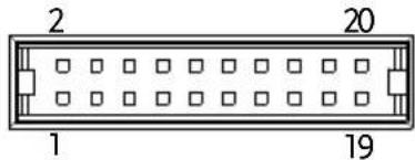 | |
| Pin name | Pin number | Description |
| I MON | 1 | Output current monitor.0 % to 100 % of the rated output current is generated as a voltage between 0 V and 10 V. |
| V MON | 2 | Output voltage monitor.0 % to 100 % of the rated output voltage is generated as a voltage between 0 V and 10 V. |
| EXT-V/R CV CONT | 3 | This line uses an external voltage or resistance to control the output voltage.External voltage control; External resistor control0 to 10 V or 0 to 10k ; 0 % to 100 % of the rated output voltage. |
| A COM | 4 | This is the common line for external signal pins 1, 2, 3, and 5. |
| EXT-V/R CC CONT | 5 | This line uses an external voltage or resistance to control the output current.External voltage control; External resistor control0 to 10 V or 0 to 10k ; 0 % to 100 % of the rated output current. |
| A COM | 6 This is the common line for external signal pins 1, 2, 3, and 5. |
| N.C. | 7 Not connected. |
| N.C. | 8 Not connected. |
| OUT ON/OFF CONT | 9 Output on/off line.On when set to a low TTL signal, Off when set to a high TTL signal.On when set to a high TTL signal, Off when set to a low TTL level signal. |
| TRIG IN | 10 Trigger signal input line.Pulled down the internal circuit to B COM using 100kΩ.The minimum pulse is width is 100us. |
| TRIG OUT | 11 Trigger signal output line.Outputs a TTL signal when a trigger out function is activated.The minimum pulse is width is 1ms. |
| B COM | 12 This is the common line for external signal pins 9, 10, and 11. |
| N.C. | 13 Not connected. |
| N.C. | 14 Not connected. |
| OUT ON Status | 15 On when the output is on (open-collector photocoupler output).1 |
| CV Status | 16 This line is On when the PPX is in CV mode (open-collector photocoupler output).1 |
| PWR OFF Status | 17 Outputs a low level signal when power is turned off. (open-collector photocoupler output).1 |
| CC Status | 18 This line is On when the PPX is in CC mode (open-collector photocoupler output).1 |
| Alarm Status | 19 On when a protection function (OVP, OCP, OTP, AC ALARM) has been activated or when an output shutdown signal is being applied (open-collector photocoupler output).1 |
| Status COM | 20 This is the common line for the status signal pins 2 to 6. |
External Voltage Control of Voltage Output
Background
External voltage control of the voltage output is accomplished using the analog control connector on the rear panel. A voltage of 0\~10V is used to control the full scale voltage of the instrument, where: Output voltage = full scale voltage × (external voltage/10)Connection
When connecting the external voltage source to the analog connector, use shielded or twisted paired wiring. text_image
PPXEXT-\ Analog connector Output Terminal 2 core shielded wire or twisted pairConnection-alt. shielding
If the wire shield needs to be grounded at the voltage source (EXT-V), then the shield cannot also be grounded at the negative (-) terminal output of the PPX power supply. This would short the output. text_image
PPXEXT Analog connector Output Terminal 2 core shielded wire or twisted pairPanel operation
1. Connect the external voltage according to the connection diagrams above. 2. Set the CV Control as External V. Page 108 Also, set Output Type per application and turn On Output Enable. 3. Press the Output key. The voltage can now be controlled with the External voltage.   The input impedance for external voltage control is a high impedance OPA input. text_image
OPA A COMExternal Voltage Control of Current Output
Background
External voltage control of the current output is accomplished using the analog control connector on the rear panel. A voltage of 0\~10V is used to control the full scale current of the instrument, where: Output current = full scale current × (external voltage/10)Connection
When connecting the external voltage source to the analog connector, use shielded or twisted paired wiring. text_image
PPXEXT Analog connector 2 core shielded wire or twisted pair 6 5 Output Terminal Pin5 → EXT-V (+) Pin6 → EXT-V (-) Wire shield → negative (-) output terminaltext_image
PPXEX7 Analog connector 2 core shielded wire or twisted pair Output Terminal Pin5 → EXT-V (+) Pin6 → EXT-V (-) Wire shield → EXT-V ground (GND)text_image
OPA A COMExternal Resistance Control of Voltage Output
Background
External resistance control of the voltage output is accomplished using the analog connector on the rear panel. A resistance of 0 10k is used to control the full scale voltage of the instrument. The output voltage (0 to full scale) can be controlled with the external resistance from 0 10k . Output voltage = full scale voltage x (external resistance/10)Connection
text_image
PPXEXT Analog connector 2 core shielded wire or twisted pair 3 4 Output TerminalSteps
1. Connect the external resistance according to the connection diagrams above. 2. Set the CV Control as External R. Page 108 Also, set Output Type per application and turn On Output Enable.| 3. Press the Output key. The voltage can now be controlled with the External resistance. | |
| !Note | Ensure the resistor(s) and cables used exceed the isolation voltage of the power supply. For example: insulation tubes with a withstand voltage higher than the power supply can be used.When choosing an external resistor ensure the resistor can withstand a high degree of heat. |
| !Note | CV and CC Slew Rate Priority (CVLS, CCLS) are disabled when using external resistance control.See the CVLS and CCLS Settings on page 51 & 55. |
| Background | External resistance control of the current output is accomplished using the analog connector on the rear panel. A resistance of 0Ω~10kΩ is used to control the full scale current of the instrument.The output current (0 to full scale) can be controlled with the external resistance from 0Ω~10kΩ.Output current = full scale current × (external resistance/10) |
Connection
text_image
PPXEXT Analog connector 2 core shielded wire or twisted pair 5 6 Output TerminalSteps
1. Connect the external resistance according to the connection diagrams above. 2. Set the CC Control as External R. Page 108 Also, set Output Type per application and turn On Output Enable. 3. Press the Output key. The current can now be controlled with the External resistance.   Note Ensure the resistor(s) and cables used exceed the isolation voltage of the power supply. For example: insulation tubes with a withstand voltage higher than the power supply can be used. When choosing an external resistor ensure the resistor can withstand a high degree of heat.  Note CV and CC Slew Rate Priority (CVLS, CCLS) are disabled when using external resistance control. See the CVLS and CCLS Settings on page 51 & 55.External Control of Output
Background
The output can be turned on or off externally using a switch. The analog control connector can be set to turn the output on from a high or low signal. The voltage across pins 9 and 12 are internally pulled to +5V with 2kΩ pull-up resistor. A short (closed switch) produces a low signal. When set to High = On, the output is turned on when the pins 9 and 12 are open. When Low = On, the output is turned on when the pins 9 and 12 are shorted.Connection
text_image
PPX +5V 2KΩ Switch 9 Analog connector 12 B COM Pin9 → Switch Pin12 → Switch Wire shield → negative (-) output terminalSteps
1. Connect the external switch according to the connection diagrams above. 2. Set Output Type per application to High or Low and turn On Output Enable. Page 108 3. The switch is now ready to set the output on or off.  When using a switch over long distances, please use a switch relay to extend the line from the coil side of the relay. flowchart
graph LR
    A["Line extension"] --> B["Switch Relay"]
    B --> C["9"]
    B --> D["12"]
    C --> E["Analog connector"]
    D --> E
    E --> F["PPX +5V 2KΩ"]
    E --> G["B COM"]
External Trigger In / Out
Background
Pin 10 is used for the external trigger input and pin 11 is used as the trigger output. Pin 12 is the B common for both pins. The trigger input can be configured to perform an action such as toggling the output on/off, load a memory setting or apply a voltage/current setting when a trigger is received. The trigger output can be configured to be active when the output is turned on/off, a voltage/current setting is changed or when a memory setting has been recalled. The trigger output pulse width can also be configured. See page 120 for details on the trigger input and trigger output configuration settings.Pinout
| Name and Pin | Description | |
| B COM | 12 | B COM for trigger pins 10 & 11. |
| TRIG OUT | 11 | Trigger output: approx. 4.5 VPulse width: approx. 1ms, Output impedance: approx. 500 ΩIt outputs a pulse when power output, V/I set operation or memory recall is executed. |
| TRIG IN | 10 | A high or low level TTL signal is applied for 100 us or longer.It receives a pulse to perform actions like power output, V/I set operation or memory recall.Pulled down the internal circuit to B COM using 100kΩ. |
text_image
Trigger input signal 10 12 PPX B COM 100kΩ Analog connector B COMRemote Monitoring
The PPX power supplies have remote monitoring support for current and voltage output. They also support monitoring of operation and alarm status. External monitoring of output voltage and current → from page 173 External monitoring of operation mode and alarm status → from page 175External Voltage and Current Monitoring
Background
The analog connector is used to monitor the current (IMON) or voltage (VMON) output. An output of 0\~10V represents the voltage or current output of 0\~ rated current/voltage output. $$ \mathrm{IMON} = (\text { current output / full scale }) \times 1 0. $$ $$ \mathrm{VMON} = (\text { voltage output / full scale }) \times 1 0. $$ External voltage and current monitoring doesn't need to be enabled in the configuration settings.VMON Connection
text_image
DMM V MON 0→10V 2 4 PPX Analog connector Output TerminalIMON Connection
text_image
DMM I MON 0→10V 1 4 PPX Analog connector Output TerminalNote
Maximum output impedance is 10KΩ. Ensure the sensing circuit has an input impedance greater than 1MΩ. The monitor outputs are strictly DC and should not be used to monitor analog components such as transient voltage response or ripple etc.CAUTION
Ensure IMON (pin 1) and VMON (pin 2) are not shorted together. This may cause damage to the unit. External Operation and Status Monitoring| Background | The analog connector can also be used to monitor the status operation and alarm status of the instrument. | |
| The pins are isolated from the power supply internal circuitry by photo couplers. Status Com (Pin 20) is a photo coupler emitter output, whilst pins 15~19 are photo coupler collector outputs. | ||
| A maximum of 30V and 8mA can be applied to each pin. | ||
| Pinout | Name and Pin | Description |
| OUT ON Status | 15 On when the output is on (open-collector photocoupler output).1 | |
| CV Status | 16 This line is On when the PPX is in CV mode (open-collector photocoupler output).1 | |
| PWR OFF Status | 17 Outputs a low level signal when power is turned off. (open-collector photocoupler output).1 | |
| CC Status | 18 This line is On when the PPX is in CC mode (open-collector photocoupler output).1 | |
| Alarm Status | 19 On when a protection function (OVP, OCP, OTP or AC Alarm) has been activated or when an output shutdown signal is being applied (open-collector photocoupler output).1 | |
| Status COM 20 This is the common line for the status signal pins 15 to 19. | ||
Schematic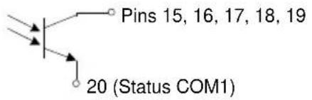 | ||
| Timing diagrams | Below are 4 example timing diagrams covering a number of scenarios. Note that pins 15~19 are all active low. | |
| CV MODE:Output turned on | The diagram below shows the timing diagram when the output is turned on when the PPX is set to CV mode. | |
| CV MODE:Output turned off | The diagram below shows the output status lines when the output is turned off in CV mode.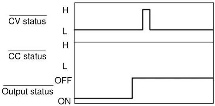 | |
flowchart
graph TD
    A["CV status"] --> B["H"]
    C["CC status"] --> D["H"]
    E["Output status"] --> F["H"]
    B --> G["L"]
    D --> H["L"]
    F --> I["L"]
flowchart
graph TD
    A["CV status"] --> B["H"]
    C["CC status"] --> D["L"]
    E["Output status"] --> F["H"]
    G["Output status"] --> H["L"]
COMMUNICATION
INTERFACE
This chapter describes basic configuration of IEEE488.2 based remote control. For a command list, refer to the programming manual, downloadable from GW Instek website, www.gwinstek.com Interface Configuration....179 USB Remote Interface 179 Configuration....179 USB CDC Function Check 180 GPIB Remote Interface....187 Configuration....187 GPIB Function Check....188 UART Remote Interface 192 Configure UART....192 UART Function Check....194 Multi Unit Connection....196 Multiple units Function Check 197 Configure Ethernet Connection.... 199 Web Server Configuration....199 Web Server Remote Control Function Check 200 Sockets Server Configuration....202 Socket Server Function Check....203Interface Configuration
USB Remote Interface Configuration| USB Configuration | PC side connector | Type A, host |
| PPX side connector | Rear panel Type B, slave | |
| Speed | 1.1 (full speed) | |
| USB Class | CDC (communications device class) |
Steps
1. Connect the USB cable to the rear panel USB B port.  DEVICE 2. Set the USB setting as Auto or Full. Page 142 3. The indicator will be shown when a remote connection has been established. text_image
GW 2wire Off Remote Control indicator 0.000 v 0.0204 A Select 0.000 V 0.0000 AUSB CDC Function Check
| Background | To test the USB CDC functionality, National Instruments Measurement and Automation Explorer can be used. This program is available on the NI website, www.ni.com., via a search for the VISA Run-time Engine page, or “downloads” at the following URL, http://www.ni.com/visa/ |
| Requirements | Operating System: Windows XP, 7, 8,10 |
Functionality check
1. In case of Window 7 64 bits, once the USB Cable was connected to PC correctly for a while (around 1 min). It may show below message at the lower right area of display. text_image
Driver Software Installation Device driver software was not successfully installed CDC-W1234567 No driver found What can I do if my device did not install properly? Closetext_image
Run Type the name of a program, folder, document, or Internet resource, and Windows will open it for you. Open: devmont.msc OK Cancel Browse...text_image
Device Manager File Action View Help tester-PC Batteries Computer Disk drives Display adapters DVD/CD-ROM drives Human Interface Devices IDE ATA/ATAPI controllers Keyboards Mice and other pointing devices Monitors Network adapters Other devices CDC-W1234567 Processors Sound, video and game controllers System devices Universal Serial Bus controllerstext_image
Device Manager File Action View Help tester-PC Batteries Computer Disk drives Display adapters DVD/CD-ROM drives Human Interface Devices IDE ATA/ATAPI controllers Keyboards Mice and other pointing devices Monitors Network adapters Other devices Process Sound System Univer Update Driver Software... Disable Uninstall Scan for hardware changes Propertiestext_image
Update Driver Software - How do you want to search for driver software? Search automatically for updated driver software Windows will search your computer and the Internet for the latest driver software for your device, unless you've disabled this feature in your device installation settings. Browse my computer for driver software Locate and install driver software manually. Canceltext_image
Update Driver Software Browse for driver software on your computer Search for driver software in this location: ● UserMaster Desktop drive Browse... Include subfolders Let me pick from a list of device drivers on my computer This list will show installed driver software compatible with the device, and all driver software in the same category as the device. Next Canceltext_image
Update Driver Software - PBL-2000 Installing driver software...text_image
Update Driver Software - CDC-W1234567 (COMDS) Windows has successfully updated your driver software Windows has finished installing the driver software for this device CDC-W1234567 Closetext_image
Device Manager File Action View Help tester-PC Batteries Computer Disk drives Display adapters DVD/CD-ROM drives Human Interface Devices IDE ATA/ATAPI controllers Keyboards Mice and other pointing devices Monitors Network adapters Ports (COM & LPT) CDC-W1234567 (COM53) Processors Sound, video and game controllers System devices Universal Serial Bus controllerstext_image
NL.com NATIONAL INSTRUMENTS Measurement & Automation Explorer Initializing Version 15.3 ©1999-2015 National Instruments. All rights reserved. NATIONAL INSTRUMENTStext_image
12 13 14 Settings Name: CDSAG POST NAME: CDSAG Start Description: SQL Status: Prepaid DATA Parameters Options: AOS-03-DCTS About the year account MIME!text_image
ASRL41:IN ISA Test Panel Configuration Input/Output N/O Trace Help NATIONAL INSTRUMENTS Serial Settings Flow Control Settings I/O Settings View Attributes Standard Settings Timeout (ms) 2000 Termination Methods Suppress End On Reads Send End On Writes Enable Termination Character End Mode For Reads Termchar End Mode For Writes None Termination Character Value Line Feed - Vn xA Error Replacement Character x0 Return Data SET Enable Termination to VL TRUE No Error I/O Protocol Normal 488.2 Strings 16 17 Refresh Apply Changestext_image
ASRL41-INSTR - VISA Test Panel Configuration Input/Output Advanced MLO Trace Help NATIONAL INSTRUMENTS Basic I/O Select or Enter Configuration *IDN7\n Bytes to Read 1024 Write Query Read Read Status Byte Clear View mixed ASCII/Hexadecimal GW-INSTEK,PPX-10H01,TW123436,V0.A4\o Copy to Clipboard lear Buffer Return Data Read Operation No Error 18 19 20 21GPIB Remote Interface
Configuration
To use GPIB, the optional GPIB option (GW Instek part number: Option 1) must be installed. This is a factory installed option and cannot be installed by the end-user. Only one GPIB address can be used at a time.Configure GPIB
1. Ensure the PPX is off before proceeding. 2. Connect the GPIB cable (GW Instek part number: GTL-258) from a GPIB controller to the GPIB port on the PPX. 3. Turn the PPX on. 4. Set the GPIB Address setting per Application. Page 141 5. The indicator will be shown when a remote connection has been established. text_image
GW 2wire Off Remote Control indicator 0.000 v 0.0204 A Select 0.000 V 0.0000 AGPIB constraints
- Maximum 15 devices altogether, 20m cable length, 2m between each device - Unique address assigned to each device - At least 2/3 of the devices turned On - No loop or parallel connection GPIB Function Check| Background | To test the GPIB functionality, National Instruments Measurement and Automation Explorer can be used. This program is available on the NI website, www.ni.com., via a search for the VISA Run-time Engine page, or “downloads” at the following URL, http://www.ni.com/visa/ |
| Requirements | Operating System: Windows XP, 7, 8, 10 |
| Functionality check | 1. Start the NI Measurement and Automation Explorer (MAX) program. Using Windows, press:Start>All Programs>National Instruments>Measurement & Automation |
text_image
GPJB-USB-HS "GPJB0" - Measurement & Automation Explorer File Edit View Tools Help My Systems Devices and Interfaces ASRL1:INSTR "COM" ASRL32:INSTR "CD" ASRL10:INSTR "LPT" GPJB-USB-HS "GPJB0" Network Devices Software Remote Systems Refresh Scan for Instruments Interactive Control Settings Name GPJB0 Vendor National Instruments Model GPJB-USB-HS Serial Number 0180490CF Status Presenttext_image
PPX-10H01 "GPIBD:8-INSTR" - Measurement & Automation Explorer File Edit View Tools Help My Systems Devices and Interfaces ASRL1:INSTR "COM1" ASRL32:INSTR "COM32" ASRL10:INSTR "LPT1" GPIB-USB-HS "GPIBD" PPX-10H01 "GPIBD:8-INSTR" Network Devices Software Remote Systems Refresh Open VISA Test Panel Communicate with Instrument GPIBB 8-INSTR Device Type GPIB Instrument VISA Alos on My System Device Status This device is working property. Help Device Usage Device installed Find out Downloaded Instrument Drivers Select the authorized you want to use: Launch Lat/VIEW/DIFinder N Lat/VIEW:2014d644bg Search IDNet(n.com/dose) and install manually. Go Settings VISA Properties Attributestext_image
GPIB VISTA - VISA Test Panel Configuration Input/Output Advanced MI UO Trace Help NATIONAL INSTRUMENTS GPIB Settings U/O Settings View Attributes Address Settings GPIB Primary Address 8 GPIB Secondary Address No Secondary Address State Information Enable Unaddressing Enable Readdressing REN Line State Asserted Refresh Apply Changes Return Data No Errortext_image
GPIB:8:INSTR - VISA Test Panel Configure Input/Output Advanced NVO Trace Help NATIONAL INSTRUMENTS GPIB Settings I/O Settings View Attributes Standard Settings Timeout (ms) 3000 Termination Methods Send End On Writes Enable Termination Character I/O Protocol Normal High Speed Termination Character Value Line Feed - VN (A) Return Data SET Enable Termination to VI_TRUE No Error 10 11 Refresh Apply Changestext_image
GPBO bus model - VISA Test Configuration Input/Output Advanced M UO less Help NATIONAL INSTRUMENTS Basic I/O Line Control Select or Enter ConfigurationIDN7.n *IDN7.n Bytes to Read 1024 Write Query Read Read Status Byte Clear View mixed ASCII/ hexadecimal TW-INSTEK, PFX-10H01, TW123456, V0.A4n Copy to Clipboard lear Buffer Return Data Read Operation No ErrorUART Remote Interface
Configure UART
Overview
The PPX uses the IN & OUT ports for UART communication coupled with RS232 (GW Instek part number: GTL-259) or RS485 adapters (GW Instek part number: GTL-260). The pin outs for the adapters are shown below.| RS232 cable with DB9 & RJ-45 shielded connectors from GTL-259 connection kit | DB-9 Connector | Remote IN Port | Remarks | ||
| Pin No. | Name | Pin No. | Name | ||
| Housing | Shield | Housing | Shield | ||
| 2 | RX | 7 | TX | Twisted pair | |
| 3 | TX | 8 | RX | ||
| 5 | SG | 1 | SG | ||
text_image
5 1 9 6| DB-9 Connector | Remote IN Port | Remarks | ||
| Pin No. | Name | Pin No. | Name | |
| Housing | Shield | Housing | Shield | |
| 9 | TXD - | 6 | RXD - | Twisted pair |
| 8 | TXD + | 3 | RXD + | |
| 1 | SG | 1 | SG | |
| 5 | RXD - | 5 | TXD - | Twisted pair |
| 4 | RXD + | 4 | TXD + | |
text_image
5 1 9 6Steps
1. Connect the RS232 serial cable or RS485 serial cable to the Remote IN port on the real panel. Connect the other end of the cable to the PC. text_image
N QNT 1 RS232 / RS485text_image
GW 2wire Off Remote Control indicator 0.000 v 0.0204 A Select 0.000 V 0.0000 AUART Function Check
Functionality check Invoke a terminal application such as Realterm. To check the COM port No., see the Device Manager in the PC Run this query command via the terminal application after the instrument has been configured for UART remote control. \*idn? This should return the Manufacturer, Model number, Serial number, and Firmware version in the following format. GW-INSTEK,PPX-10H01,TW123456,V0.A4 Manufacturer: GW-INSTEK Model number : PPX-10H01 Serial number : TW1234567 Firmware version : V0.A4  Note For further details, please see the programming manual, available on the GW Instek web site @ www.gwinstek.com.Multiple Unit Connection
The PPX power supplies can have up to 31 units daisy-chained together using the 8 pin connectors (IN OUT ports) on the rear panel. The first unit in the chain is remotely connected to a PC using GTL-260 (RS485 cable with DB9 connector). Each subsequent unit is daisy-chained to the next using a RS485 local bus. flowchart
graph LR
    A["Computer"] -->|GTL - 260| B["GTL - 262"]
    B --> C["Max 31 units"]
    B --> D["GTL - 262"]
    D --> E["Max 31 units"]
    D --> F["GTL - 262"]
    F --> G["Max 31 units"]
Multi Unit Connection
Operation
1. Connect the first unit's IN port to a PC using RS485 cable with DB9 & RJ-45. 2. Connect the OUT port on the first unit to the IN port of the second unit using the slave serial link cable (black plug) supplied in the GTL-262 connection kit. text_image
Unit #1 RS 485/232 To PC PSU-485 cable with DB9 & RJ-45 IN OUT Unit #2 RS 485/232 serial link cable (black plug) IN OUT Unit #N RS 485/232 serial link cable (black plug)text_image
UART Baud Rate 9600 Data Bits 8 Bits Stop Bits 1 Parity None Mode RS485 Address 5 Return| Functionality check | Invoke a terminal application such as Realterm.To check the COM port No, see the Device Manager in the PC.For this function check, we will assume that the one unit is assigned to address 0, while other is assigned address 5. |
| ADR 0OK*IDN?GW-INSTEK,PPX-2005,TW123456,V0.A2VOLT 5OKVOLT? |
Configure Ethernet Connection
The Ethernet interface can be configured for a number of different applications. Ethernet can be configured for basic remote control or monitoring using a web server or it can be configured as a socket server. The PPX series supports both DHCP connections so the instrument can be automatically connected to an existing network or alternatively, network settings can be manually configured.| Ethernet configuration | For details on how to configure the Ethernet settings, please see the configuration chapter on page 138. | |
| Parameters | MAC Address (display only) | Hostname (display only) |
| DHCP On/Off | IP Address | |
| Subnet Mask | Gateway IP | |
| DNS Address | Web Server On/Off | |
Web Server Configuration
Configuration
This configuration example will configure the PPX as a web server and use DHCP to automatically assign an IP address to the PPX. 1. Connect an Ethernet cable from the network to the rear panel Ethernet port.  LAN 2. Turn On DHCP and Web Server settings. Page 138 & 143 3. The indicator will be shown when a remote connection has been established. text_image
GW 2wire Off Remote Control indicator 0.000 v 0.0204 A Select 0.000 V 0.0000 AWeb Server Remote Control Function Check
Functionality check Enter the IP address of the power supply in a web browser after the instrument has been configured as a web server. The web server allows you to monitor the function settings of the PPX. The web browser interface appears as follows. text_image
GWINSTEK Simply Reliable Visit Our Site Support | Contact Us Welcome Page PPX Series Web Control Pages System Information Network Configuration Thanks For Your Using Manufacturer: QW-05873X Serial Number: 196124-056 Description: QW-058718,PPS-0003 External Status: 01.0.1 Maintenance: 0-123456 APPROVATION: 0-120159,0000. External Control IP Address: 172.16.26-40 Circuit Mask: 255.255.123.0 Delivery: 172.16.0254 EMS: 172.16.1.252 MAC Address: 86-31-23-32-32-79 HOLD State: 08 Figure of Dimensions OVA HCPD Diameter: TCJ579-172.16.26-40.22 Sequence DesignSockets Server Configuration
Configuration
This configuration example will configure the PPX socket server. The following configuration settings will manually assign the PPX an IP address and enable the socket server. The socket server port number is fixed at 2268. 1. Connect an Ethernet cable from the network to the rear panel Ethernet port.  2. Turn Off DHCP setting followed by setting the relevant settings including IP Address, Subnet Mask, Gateway IP and DNS Address. Page 140 3. The indicator will be shown when a remote connection has been established. text_image
GW 2wire Off Remote Control indicator 0.000v 0.0204A Select 0.000 V 0.0000 A| Background | To test the socket server functionality, National Instruments Measurement and Automation Explorer can be used. This program is available on the NI website, www.ni.com., via a search for the VISA Run-time Engine page, or “downloads” at the following URL, http://www.ni.com/visa/ |
| Requirements | Operating System: Windows XP, 7, 8, 10 |
Functionality check
1. Start the NI Measurement and Automation Explorer (MAX) program. Using Windows, press: Start>All Programs>National Instruments>Measurement & Automation text_image
ni.com NATIONAL INSTRUMENTS Measurement & Automation Explorer Initializing Version 15.3 ©1998-2015 National Instruments. All rights reserved. NATIONAL INSTRUMENTStext_image
Network Devices - Measurement & Automation Explorer File Edit View Tools Help My System Devices and Interfaces ASRL1:INSTR "COM1" ASRL3:INSTR "COM1*32" ASRL10:INSTR Network Devices Software Remote Systems Add Network Device Product Nametext_image
Create New ... Choose the type of LAN resource you want to add. Choose the type of TCP/IP resource you wish to add. Auto-detect of LAN Instrument Use this option to select from a list of VXI-11 LAN/LXI instruments detected on your local subnet. Manual Entry of LAN Instrument Use this option if any VXI-11 LAN/LXI instrument is on another network. Manual Entry of Raw Socket Use this option to communicate with an Ethernet device over a specific port number. < Back Next > Finish Canceltext_image
Create New ... Enter the LAN resource details. NATIONAL INSTRUMENTS Enter the TCP/IP address of your VGA network resource in the form of:xxx:xxx:xxx:thehostname of the device, or a computer@some.doman Hostname or IP address 172.16.5.21 Port Number 2268 Validate Measurement & Automation Explorer 7 Successfully opened a VISA session to "TCPIP0::172.16.5.21::2268::SOCCET" 确定 < Back Next > Finish Canceltext_image
Create New Specify an alias for this resource (optional). You can specify an alias for this device. An alias is a logical name for a device that makes it easier to identify your instrument. Use aliases in your code when opening sessions to devices without specifying their full VISA resource strings. You may assign or change the alias at a later time through the alias editor or by clicking on the device to rename it. Type in the alias you want to assign to this device or leave the alias field blank to not assign an alias to this device. Resource Name: TOP100 21:268:50CKET Alias: PPX_DCI < Back Next > Finish Cancel 9 10text_image
TCP/IP0:172.16.5.21:2288:SOCKET "PPX_DC1" - Measurement & Automation Explorer File Edit View Tools Help My System Devices and Interfaces ASRL11:INSTR "COM1" ASRL12:INSTR "COM32" ASRL10:INSTR "LPT1" Network Devices TCP/IP0:172.16.5.21:2288:SOCKET "PPX_DC1" Software Remote Systems Refresh Open VISA Test Panel Settings Name PPX_DC1 Hostname 172.16.5.21 IPv4 Address 172.16.5.21 Status Present Port Number 2268 VISA Resource Name TCP/IP0:172.16.5.21:2288:SOCKETtext_image
13 14 TCP/IP Settings I/O Settings View Attributes Standard Settings Timeout (ms) 2000 I/O Protocol Normal 488.2 Strings Termination Methods Send End On Writes Suppress End On Reads Enable Termination Character Termination Character Value Line Feed - \n ×A Return Data SET Enable Termination to VL_TRUE No Error 15 16 Refresh Apply Changestext_image
TCPIP0:172.16.5.21-2268: SOCKET Test Panel Configuration Input/Output Advanced NIMO Trace Help NATIONAL INSTRUMENTS Basic I/O Select or Enter Command#IDN?n *IDN?n Bytes to Read 1024 Write Query Read Read Status Byte Clear View mixed ASCII/ hexadecimal GW-INSTEK,PPX-10H01,TW123456,V0.A4# Copy to Clipboard lear Buffer Return Data Read Operation VISA: (Hex 0x3FFF0005) The specified termination character was read.F_AQ
• How often should the power supply be calibrated? • The OVP voltage is triggered earlier than expected. • Can I combine more than 1 cable together for the output wiring? • The accuracy does not match the specification. How often should the power supply be calibrated? The PPX should be calibrated by an authorized service center at least every 2 years. For details regarding calibration, see your local dealer or GWInstek at www.gwinstek.com / marketing@goodwill.com.tw. The OVP voltage is triggered earlier than expected. When setting the OVP voltage, take into account the voltage drop from the load cables. As the OVP level is set from the output terminals and not the load terminals, the voltage at the load terminals may be slightly lower. Can I combine more than 1 cable together for the output wiring? Yes. Cables can be used together (in parallel) if the current capacity of a single cable is insufficient. However the withstand voltage should also be taken into account. Ensure the cables are twisted together and are the same length. The accuracy does not match the specification. Make sure the device is powered On for at least 30 minutes, within 23^ C±5°C. This is necessary to stabilize the unit to match the specification. For more information, contact your local dealer or GWInstek at www.gwinstek.com / marketing@goodwill.com.tw.APPENDIX
PPX Factory Default Settings
The following default settings are the factory configuration settings for the power supply. For details on how to return to factory default settings, see page 62.| Initial | Default Setting |
| Output | Off |
| LOCK | Disabled |
| Voltage Set | 0.000 V |
| Current Set | 0.0000 A |
| Output | Default Setting |
| Output On Dly(Delay) | 00(hour):00(minute):00.00(sec) |
| Output Off Dly(Delay) | 00(hour):00(minute):00.00(sec) |
| Remote Sense | 2 Wire |
| V/I Slew Rate | CVHS = CV high speed priority |
| R_V(Rising Voltage) Slew Rate | 0.001 V/ms (PPX-10H01) |
| 0.0001 V/ms (Other) | |
| F_V(Falling Voltage) Slew Rate | 0.001 V/ms (PPX-10H01) |
| 0.0001 V/ms (Other) | |
| R_C(Rising Current) Slew Rate | 0.00001 A/ms (PPX all series) |
| F_C(Falling Current) Slew Rate | 0.00001 A/ms (PPX all series) |
| Measurement | Default Setting |
| Measure Average | Off |
| Voltage Range | Auto |
| Current Range | Auto |
| EXT (External) Control | Default Setting |
| CV Control | Front Panel |
| CC Control | Front Panel |
| Output Type | High |
| Output Enable | Off |
| TRIG(Trigger Control) | Default Setting |
| Trigin Level | High |
| Trigin Action | None |
| Trigin Voltage | 0.000 V |
| Trigin Current | 0.0000 A |
| Trigin Memory | M1 |
| Trigout Level | Low |
| Trigout Source | None |
| Trigout Width | 1.0 ms |
| PWR(Power) On Config | Default Setting |
| Power On Status | Safe |
| Constant PWR(Power) | Default Setting |
| Control | Off |
| Power | (1.05 X Vrate) * (1.05 X Irate) |
| Temperature | Default Setting |
| Control | Off |
| Unit | °C |
| Output Safe | Off |
| Monitor | 100.0 °C |
| Adjust | 0.0 °C |
| Save/Recall | Default Setting |
| Save Mem(Memory) Set | M1 |
| Recall Mem(Memory) Set | M1 |
| Utility - Buzzer | Default Setting |
| Protect | On |
| Keyboard | Off |
| Utility - Bleeder | Default Setting |
| Bleeder | On |
| APP - AH/WH Meter (License Key) | Default Setting |
| Mode | Disable |
| AHour | 999999999.999 Ah |
| WHour | 999999999.999 Wh |
| Protect | Default Setting |
| Voltage Limit | Off |
| UVL | 0.000 V |
| OVP Level | 1.1 X Vrate |
| Current Limit | Off |
| OCP Level | 1.1 X Irate) |
| OCP Delay | 0.050 s |
PPX Specifications
The specifications apply when the PPX is powered on for at least 30 minutes. Input ratings (AC rms)| Model | PPX-1005 | PPX-2002 | PPX-2005 | PPX-3601 | PPX-3603 | PPX-10H01 |
| Nominal input voltage^*1 | 100Vac / 120Vac / 220Vac / 240Vac, 50Hz / 60Hz, single phase | |||||
| Input voltage range | ±10% | |||||
| Input frequency range | 47Hz to 63Hz | |||||
| Max. Inrush current | ≤ 25Amax | ≤ 20Amax | ≤ 30Amax | ≤ 35Amax | ≤ 40Amax | ≤ 30Amax |
| Max. power consumption | 200VA | 150VA | 300VA | 150VA | 300VA | 300VA |
| Model | PPX-1005 | PPX-2002 | PPX-2005 | PPX-3601 | PPX-3603 | PPX-10H01 | |
| Rating | Output voltage | 10.000V | 20.000V | 20.000V | 36.000V | 36.000V | 100.00V |
| Output current | 5.0000A | 2.0000A | 5.0000A | 1.0000A | 3.0000A | 1.0000A | |
| Output power | 50W | 40W | 100W | 36W | 108W | 100W | |
| Voltage | Setting range (105%) | 0V to 10.5V | 0V to 21.0V | 0V to 21.0V | 0V to 37.8V | 0V to 37.8V | 0V to 105.0V |
| Setting resolution | 0.2mV | 0.5mV | 0.5mV | 1mV | 1mV | 2mV | |
| Setting accuracy (23°C±5°C) | ±(0.03% of setting + 3mV) | ±(0.03% of setting + 5mV) | ±(0.03% of setting + 5mV) | ±(0.03% of setting + 8mV) | ±(0.03% of setting + 8mV) | ±(0.03% of setting + 20mV) | |
| Line regulation*7 | ±(0.01% of setting + 1mV) | ±(0.01% of setting + 1mV) | ±(0.01% of setting + 1mV) | ±(0.01% of setting + 3mV) | ±(0.01% of setting + 3mV) | ±(0.01% of setting + 7mV) | |
| Load regulation*8 | ±(0.01% of setting + 2mV) | ±(0.01% of setting + 2mV) | ±(0.01% of setting + 3mV) | ±(0.01% of setting + 3mV) | ±(0.01% of setting + 4mV) | ±(0.01% of setting + 7mV) | |
| Transient response *1 | <50us | <100us | |||||
| Ripple noise (Vrms*2/Vpp*3) | 0.35mVrms/<6mVpp | 0.5mVrms/<8mVpp | 0.5mVrms/<8mVpp | 0.8mVrms/<10mVpp | 0.8mVrms/<10mVpp | 1.2mVrms/<15mVpp | |
| Rise time*4 | Rated load | ≤20ms | ≤50ms | ≤100ms | |||
| No load | ≤20ms | ≤50ms | ≤100ms | ||||
| Fall time*5 | Rated load | ≤10ms | ≤20ms | ≤50ms | |||
| No load | ≤100ms | ≤150ms | ≤250ms | ||||
| Maximum remote sensing compensation voltage (single line) | 1V | 3V | ||||
| Temperature Coefficient (TYP.)*6 | 100 ppm/°C | |||||
| Setting range (105%) | 0A to 5.25A | 0A to 2.1A | 0A to 5.25A | 0A to 1.050A | 0A to 3.15A | 0A to 1.050A |
| Setting resolution | 0.1mA | 0.05mA | 0.1mA | 0.02mA | 0.1mA | 0.02mA |
| Setting accuracy (23°C±5°C) | ±(0.05% of setting + 3.0mA) | ±(0.05% of setting + 1.0mA) | ±(0.05% of setting + 3.0mA) | ±(0.05% of setting + 0.5mA) | ±(0.05% of setting + 1.5mA) | ±(0.05% of setting + 1.0mA) |
| Line regulation*7 | ±(0.02% of setting + 250uA) | ±(0.02% of setting + 100uA) | ±(0.02% of setting + 250uA) | ±(0.02% of setting + 50uA) | ±(0.02% of setting + 150uA) | ±(0.02% of setting + 50uA) |
| Load regulation*9 | ±(0.02% of setting + 250uA) | ±(0.02% of setting + 100uA) | ±(0.02% of setting + 250uA) | ±(0.02% of setting + 50uA) | ±(0.02% of setting + 150uA) | ±(0.02% of setting+ 50uA) |
| Ripple (Arms*2) noise | 2mA | 1mA | 2mA | 400uA | 1mA | 1mA |
| Temperature Coefficient (TYP.)*6 | 200 ppm/°C | |||||
| Model | PPX-1005 | PPX-2002 | PPX-2005 | PPX-3601 | PPX-3603 | PPX-10H01 | |
| Voltage Range | Hight | 10.000V | 20.000V | 20.000V | 36.000V | 36.000V | 100.00V |
| Low | 1.0000V | 2.0000V | 2.0000V | 3.6000V | 3.6000V | 10.000V | |
| Current Range | Hight | 5.0000A | 2.0000A | 5.0000A | 1.0000A | 3.0000A | 1.0000A |
| Mid | 500.00mA | 200.00mA | 500.00mA | 100.00mA | 300.00mA | 100.00mA | |
| Low | 50.000mA | 20.000mA | 50.000mA | 10.000mA | 30.000mA | 10.000mA | |
| L-Low | 5.0000mA | 2.0000mA | 5.0000mA | 1.0000mA | 3.0000mA | 1.0000mA | |
| Measurement Resolution | Voltage(H) | 1mV | 10mV | ||||
| Voltage(L) | 0.1mV | 1mV | |||||
| Current(H) | 0.1mA | 0.1mA | |||||
| Current(M) | 0.01mA | 0.01mA | |||||
| Current(L) | 0.001mA | 0.001mA | |||||
| Current(LL) | 0.0001mA | 0.0001mA | |||||
| Voltage(H/L) | ±(0.03% of rdg +2mV) | ±(0.03% of rdg +4mV) | ±(0.03% of rdg +5mV) | ±(0.03% of rdg +6mV) | ±(0.03% of rdg +8mV) | ±(0.03% of rdg +15mV) | |
| Measurement Accuracy | Temperature Coefficient*1(TYP.) | 100 ppm/°C | |||||
| Current(H/M) | ±(0.05% of rdg + 2.5mA) | ±(0.05% of rdg + 1.0mA) | ±(0.05% of rdg + 2.5mA) | ±(0.05% of rdg + 0.4mA) | ±(0.05% of rdg + 1.2mA) | ±(0.05% of rdg + 1.0mA) | |
| Current(L/LL) | ±(0.1% of rdg + 40uA) | ±(0.1% of rdg + 24uA) | ±(0.1% of rdg + 40uA) | ±(0.1% of rdg + 16uA) | ±(0.1% of rdg + 28uA) | ±(0.1% of rdg + 24uA) | |
| Temperature Coefficient*1(TYP.) | 200 ppm/°C | ||||||
| Model | PPX-1005 | PPX-2002 | PPX-2005 | PPX-3601 | PPX-3603 | PPX-10H01 | |
| Temperature (K-Type Thermocouple) | Range | -200°C~+1372°C | |||||
| Resolution | 0.25°C | ||||||
| Accuracy | ±(0.5% + 2°C) | ||||||
| Model | PPX-1005 | PPX-2002 | PPX-2005 | PPX-3601 | PPX-3603 | PPX-10H01 | |
| Over Voltage Protection (OVP) | Operation | Turns the output off, displays OVP and lights ALARM | |||||
| Setting range | 0.5V to 11.0V | 1.0V to 22.0V | 1.0V to 22.0V | 1.8V to 39.6V | 1.8V to 39.6V | 5.0V to 110.0V | |
| (5% to 110% of the rated output voltage) | |||||||
| Setting Accuracy | ±(1% of rating) | ||||||
| Over Current Protection (OCP) | Operation | Turns the output off, displays OCP and lights ALARM | |||||
| Setting range | 0.25A to 5.5A | 0.1A to 2.2A | 0.25A to 5.5A | 0.05A to 1.1A | 0.15A to 3.3A | 0.05A to 1.1A | |
| (5% to 110% of the rated output current) | |||||||
| Setting Accuracy | ±(1% of rating) | ||||||
| Over Temperature Protection (OTP) | Operation | Turns the output off, displays OTP and lights ALARM | |||||
| Model | PPX-1005 | PPX-2002 | PPX-2005 | PPX-3601 | PPX-3603 | PPX-10H01 | |
| External Voltage Control output voltage | Accuracy | 0% to 100% of the rated output voltage in the range of 0V to 10V | |||||
| 1% of rating | |||||||
| External Voltage Control output current | Accuracy | 0% to 100% of the rated output voltage in the range of 0V to 10V | |||||
| 1% of rating | |||||||
| External Resistor Control output voltage | Accuracy | 0% to 100% of the rated output voltage in the range of 0Ω to 10kΩ | |||||
| 1% of rating | |||||||
| External Resistor Control output current | Accuracy | 0% to 100% of the rated output voltage in the range of 0Ω to 10kΩ | |||||
| 1% of rating | |||||||
| OUTPUT ON/OFF CONT | Output on/off control | Possible logic selections:Turn the output on using a LOW (0 V to 0.5 V) or short-circuit, turn the output off using a HIGH (4.5 V to 5 V) or open-circuit.Turn the output on using a HIGH (4.5 V to 5 V) or open-circuit, turn the output off using a LOW (0 V to 0.5 V) or short-circuit. | |||||
| Monitor signal output | Voltage monitor (V MON) | 10.00V±0.1V (at rated voltage output) | |||||
| 0V±0.1V (at 0V output) | |||||||
| Current monitor (I MON) | 10.00V±0.1V (at rated current output) | ||||||
| 0V±0.1V (at 0A output) | |||||||
| Status signal Out^*2 | OUTON/OFF STATUS | Turns on when the output is on | |||||
| CV STATUS | Turns on during CV operation | ||||||
| CC STATUS | Turns on during CC operation | ||||||
| ALM STATUS | Turns on when an alarm has been activated | ||||||
| PWR ON STATUS | Turns on when the power is turned on | ||||||
| Model | PPX-1005 | PPX-2002 | PPX-2005 | PPX-3601 | PPX-3603 | PPX-10H01 |
| LAN | MAC Address, DNS IP Address, User Password, Gateway IP Address, Instrument IP Address, Subnet Mask | |||||
| USB | Type A: Host, Type B: Slave, Speed: 1.1/2.0, USB-CDC | |||||
| RS-232/RS-485 | Complies with the EIA-RS-232/RS-485 specifications (excluding the connector) | |||||
| Model | PPX-1005 | PPX-2002 | PPX-2005 | PPX-3601 | PPX-3603 | PPX-10H01 | |
| Weight | Approx. 5.5kg | ||||||
| Dimensions (mm) | 107(W)×124(H)×313(D) (not including protrusions) | ||||||
| Operating environment | Indoor use, Overvoltage Category II | ||||||
| Operating temperature | 0°C to 40°C | ||||||
| Storage temperature | -20°C to 70°C | ||||||
| Operating humidity | 20% to 80% RH; No condensation | ||||||
| Storage humidity | 20% to 85% RH; No condensation | ||||||
| Altitude | Maximum 2000m | ||||||
| EMC | Complies with the European EMC directive 2014/30/EU for Class A test and measurement products. | ||||||
| Safety | Complies with the European Low Voltage Directive 2014/35/EU and carries the CE-marking. | ||||||
| Withstand voltage | Between input and chassis | No abnormalities at 1500 Vac for 1 minute. | |||||
| Between input and output | No abnormalities at 3000 Vac for 1 minute. | ||||||
| Between output and chassis | No abnormalities at 500 Vdc for 1 minute. | ||||||
| Insulation resistance | Between input and chassis | 500 Vdc, 100MΩ or more | |||||
| Between input and output | 500 Vdc, 100MΩ or more | ||||||
| Between output and chassis | 500 Vdc, 100MΩ or more | ||||||
PPX Dimensions
PPX Series Declaration of Conformity
WeGOOD WILL INSTRUMENT CO., LTD.
declare that the below mentioned product Type of Product: Programmable High Precision DC Power Supply Model Number: PPX-1005 / PPX-2002 / PPX-2005 / PPX-3601 / PPX-3603 / PPX-10H01 are herewith confirmed to comply with the requirements set out in the Council Directive on the Approximation of the Law of Member States relating to EMC (2014/30/EU), LVD (2014/35/EU), WEEE (2012/19/EU) and RoHS (2011/65/EU). For the evaluation regarding the Electromagnetic Compatibility and Low Voltage Directive, the following standards were applied:| ◎ Electric Magnetic Compatibility Directive 2014/30/EU | ||
| EN 61326-1 :EN 61326-2-1: | Electrical equipment for measurement, control and laboratory use — EMC requirements (2013) | |
| Conducted and Radiated EmissionsEN 55011:2016+A1:2017 Class AEN 55032:2015 | Electrical Fast TransientsEN 61000-4-4: 2012 | |
| Current HarmonicEN 61000-3-2:2019 | Surge ImmunityEN 61000-4-5: 2014+A1:2017 | |
| Voltage FluctuationEN 61000-3-3:2013+A1:2019 | Conducted SusceptibilityEN 61000-4-6: 2014 | |
| Electrostatic DischargeEN 61000-4-2: 2009 | Power Frequency Magnetic FieldEN 61000-4-8:2010 | |
| Radiated ImmunityEN 61000-4-3:2006+A1:2008+A2:2010 | Voltage Dips/ InterruptsEN 61000-4-11: 2004+A1:2017 | |
| ◎Low Voltage Directive 2014/35/EU | ||
| Safety Requirements | EN 61010-1:2010 / A1:2019(Third Edition) | |