PPH-1510D - Measurement GW Instek - Free user manual and instructions
Find the device manual for free PPH-1510D GW Instek in PDF.

User questions about PPH-1510D GW Instek
0 question about this device. Answer the ones you know or ask your own.
Ask a new question about this device
Download the instructions for your Measurement in PDF format for free! Find your manual PPH-1510D - GW Instek and take your electronic device back in hand. On this page are published all the documents necessary for the use of your device. PPH-1510D by GW Instek.
USER MANUAL PPH-1510D GW Instek
Programmable High Precision Dual Output DC Power Supply
PPH-1503D/PPH-1506D/ PPH-1510D
User Manual
GW INSTEK PART NO. 82PH-1503DED1
Copyright Statement
This manual contains proprietary information, which is protected by copyright. All rights are reserved. No part of this manual may be photocopied, reproduced or translated to another language without prior written consent of Good Will company.
The information in this manual was correct at the time of printing. However, Good Will continues to improve products and reserves the rights to change specification, equipment, and maintenance procedures at any time without notice.
Good Will Instrument Co., Ltd.
No. 7-1, Jhongsing Rd., Tucheng Dist., New Taipei City 236, Taiwan.
Table of Contents
SAFETY INSTRUCTIONS 5
OVERVIEW 10
Introduction....10
Key Features 12
Operating Principals 14
Front Panel....16
Rear Panel 22
Constant Voltage/Constant Current
Crossover Characteristics 24
GETTING STARTED 25
Start Up....25
Load and DVM Connection....26
Turning the Output On/Off 28
MAIN MENU OVERVIEW.... 29
Function Description 30
BASIC OPERATION 32
Source Function 32
DVM 43
Pulse Current Measurement 45
Long integration....51
Battery simulation function 56
Current Sink Function....57
External Relay Control 59
Sequence Function 62
SAVE/RECALL 64
Restore Factory Default Settings....67
The Factory Default Settings 67
SYSTEM SETTINGS.... 69
System Information 69
Utility Settings 70
Firmware Upgrading....72
System Real Time Clock Setting 73
Description of Using Flash Drive....74
REMOTE CONTROL.... 79
Remote Control 79
Command Syntax....86
Command List....90
Command Details....95
SCPI Status Registers SCPI....130
Errors 138
APPENDIX....142
Replacing the Fuse 142
Battery Replacement.... 143
Specifications.... 144
Optional Accessories.... 146
Declaration of Conformity 147
SAFETY INSTRUCTIONS
This chapter contains important safety instructions that you must follow during operation and storage. Read the following before any operation to insure your safety and to keep the instrument in the best possible condition.
Safety Symbols
These symbols may appear in the manual or on the instrument.
WARNING: Identifies conditions or practices that could result in injury or loss of life.
CAUTION Caution: Identifies conditions or practices that could result in damage to the PPH or to other properties.
DANGER High Voltage
Attention Refer to the Manual
Protective Conductor Terminal
Earth (ground) Terminal
Do not dispose electronic equipment as unsorted municipal waste. Please use a separate collection facility or contact the supplier from which this instrument was purchased.
Safety Guidelines
| General GuidelineCAUTION | Do not place any heavy object on the unit.Avoid severe impact or rough handling that leads to damaging the unit.Do not discharge static electricity to the unit.Do not block the cooling fan opening.Do not perform measurements on circuits that are directly connected to mains power.Do not disassemble the PPH unless you are qualified.(Measurement categories) EN 61010-1:2010 specifies the measurement categories and their requirements as follows. The PPH-1503D/1506D /1510D falls under category I.Measurement category IV is for measurement performed at the source of low-voltage installation.Measurement category III is for measurement performed in the building installation.Measurement category II is for measurement performed on the circuits directly connected to the low voltage installation.Measurement category I is for measurements performed on circuits not directly connected to Mains. |
| Power SupplyWARNING | AC Input voltage range: 90VAC~264VACFrequency: 50Hz/60HzTo avoid electrical shock connect the protective grounding conductor of the AC power cord to an earth ground. |
| FuseWARNING | Fuse type: T2.0A/250V (PPH-1503D)T2.5A/250V PPH-1506D/1510D)To prevent fire, replace the fuse only with the specified type and rating.Disconnect the power cord before replacing the fuse.Make sure the cause of fuse blowout is fixed before replacing the fuse. |
| Cleaning the power supply | Disconnect the power cord before cleaning the oscilloscope.Use a soft cloth dampened in a solution of mild detergent and water. Do not spray any liquid into the oscilloscope.Do not use chemicals containing harsh products such as benzene, toluene, xylene, and acetone. |
| Operation Environment | Location: Indoor, no direct sunlight, dust free, almost non-conductive pollution (Note below)Relative Humidity: < 80%Altitude: < 2000mTemperature: 0°C to 40°C |
| (Pollution Degree) EN 61010-1:2010 specifies pollution degrees and their requirements as follows. The PPH-1503D/1506D/1510D falls under degree 2.Pollution refers to “addition of foreign matter, solid, liquid, or gaseous (ionized gases), that may produce a reduction of dielectric strength or surface resistivity”.Pollution degree 1: No pollution or only dry, non-conductive pollution occurs. The pollution has no influence.Pollution degree 2: Normally only non-conductive pollution occurs. Occasionally, however, a temporary conductivity caused by condensation must be expected.Pollution degree 3: Conductive pollution occurs, or dry, non-conductive pollution occurs which becomes conductive due to condensation which is expected. In such conditions, equipment is normally protected against exposure to direct sunlight, precipitation, and full wind pressure, but neither temperature nor humidity is controlled. |
Storage environment
- Location: Indoor
- Relative Humidity: < 70%
• Temperature: -10^ to 70^
Power cord for the United Kingdom
When using the power supply in the United Kingdom, make sure the power cord meets the following safety instructions.
NOTE: This lead/appliance must only be wired by competent persons
WARNING: THIS APPLIANCE MUST BE EARTHED
IMPORTANT: The wires in this lead are coloured in accordance with the following code:
Green/ Yellow: Earth
Blue: Neutral
Brown: Live (Phase)

As the colours of the wires in main leads may not correspond with the coloured marking identified in your plug/appliance, proceed as follows:
The wire which is coloured Green & Yellow must be connected to the Earth terminal marked with either the letter E, the earth symbol or coloured Green/Green & Yellow.
The wire which is coloured Blue must be connected to the terminal which is marked with the letter N or coloured Blue or Black.
The wire which is coloured Brown must be connected to the terminal marked with the letter L or P or coloured Brown or Red.
If in doubt, consult the instructions provided with the equipment or contact the supplier.
This cable/appliance should be protected by a suitably rated and approved HBC mains fuse: refer to the rating information on the equipment and/or user instructions for details. As a guide, a cable of 0.75mm ^2 should be protected by a 3A or 5A fuse. Larger conductors would normally require 13A types, depending on the connection method used.
Any exposed wiring from a cable, plug or connection that is engaged in a live socket is extremely hazardous. If a cable or plug is deemed hazardous, turn off the mains power and remove the cable, any fuses and fuse assemblies. All hazardous wiring must be immediately destroyed and replaced in accordance to the above standard.

VERVIEW
This chapter contains a brief introduction to PPH-1503D/1506D/1510D, the main features, as well as an overview of the front and rear panel. Use the Getting Started chapter on page 25 to start up instructions and how to setup the appropriate operation environment.
Introduction
Overview
The PPH-1503D/1506D /1510Dis a high-precision, compact, dual output, multifunction, programmable DC power supply with flexible operating configurations. In addition to the basic power supply functionality, it is also able to measure pulse current, the average current over long periods of time and other functions such as battery simulation.
The PPH-1503D/1506D/1510D is designed for testing the power consumption of battery powered wireless communication devices (e.g. cell phones). Such devices often have large load variations within a short time span. The high precision power supply has excellent voltage stability during pulsed loads and is capable of simultaneously measuring the pulse current, even for very short pulses. In addition, the power supply is able to sink current, allowing it to simulate the characteristics of a discharged rechargeable battery for testing chargers and charge control circuits.
| Basic Power Supply Function | The PPH-1503D/1506D/1510D works as a conventional power supply with automatic CC/CV crossover. Parameters such as the output voltage, current, read back refresh rate, data sampling period, power-on status, OVP and current range can be configured using the control panel. The voltage and current settings and the actual voltage/current are displayed on the LCD. For details, see page 32. |
| Pulse Current Measurement Function | The PPH-1503D/1506D /1510D can measure the change in instantaneous current and the current of extremely short pulses. The readback refresh rate, data sampling period, trigger delay and trigger level can be set by the front panel keys and is displayed on the LCD. For details see page 45. |
| Current Measurement over Long Periods | This function can measure the average current of one or more pulses. The readback refresh rate, trigger mode, and trigger timeout and trigger level settings are controlled by the front panel keys and are displayed on the LCD display. For details, see page 51. |
| Battery Simulation Function | The function can simulate a battery by setting the internal resistance of the power source and also display the real-time voltage and current on the LCD. For details, see page 56. |
| Current Sink Features | When the voltage of an external power source is greater than the high-speed power supply output, the system will automatically work as an electronic load to sink current. For details, see page 57. |
| Digital Volt Meter | The PPH-1503D/1506D/1510D has a DVM function that can measure DC voltages in the range of 0~20VDC. For details, see page 43. |
| Remote Control | To meet the various needs of customers, the PPH-1503D/1506D/1510D is designed for USB, GPIB and LAN remote control. For details, see page 79. |
| Additional Features | The PPH-1503D/1506D /1510D has external relay control signals for customers. The relay control signals are synced to the pulse current measurement feature. For details, see page 59. |
Key Features
| Features | Low noise: Thermostatically controlled fan.Compact, lightweight.3.5 inch TFT display. |
| Operation | Constant voltage and constant current operation (CV/CC).Output on/off control (ON/OFF).CH1 Front and Rear output control key (FRONT/REAR).Digital panel control.5 groups of save/recall settings and 10 automatically generated power-on settings.Digital voltage and current settings.Alarm buzzer (BEEP).Key lock function (LOCK). |
| Protection Features | Overvoltage and overcurrent protection (OVP/Trip).Overtemperature protection (OTP). |
Interface
- USB remote control.
- GPIB remote control.
• LAN remote control.
Operating Principals
Overview
The PPH-1503D/1506D/1510D mainly consists of the follow components:
• AC to DC Switching power supply
• DC to DC Buck converter circuit
- Precision output control circuit
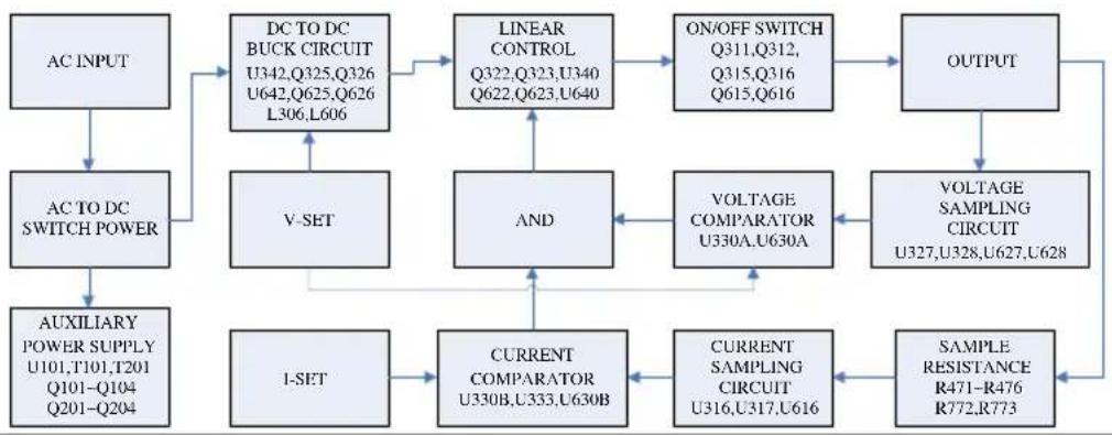
The block diagram below shows a function description of each of the circuits. The following page will show detailed descriptions of each component.
Block Diagram
flowchart
graph TD
    A["AC INPUT"] --> B["AC TO DC SWITCH POWER"]
    B --> C["AUXILIARY POWER SUPPLY U101,T101,T201 Q101-Q104 Q201-Q204"]
    C --> D["DC TO DC BUCK CIRCUIT U342,Q325,Q326 U642,Q625,Q626 L306,L606"]
    D --> E["LINEAR CONTROL Q322,Q323,U340 Q622,Q623,U640"]
    E --> F["ON/OFF SWITCH Q311,Q312, Q315,Q316 Q615,Q616"]
    F --> G["OUTPUT"]
    G --> H["VOLTAGE SAMPLING CIRCUIT U327,U328,U627,U628"]
    H --> I["VOLTAGE COMPARATOR U330A,U630A"]
    I --> J["AND"]
    J --> K["CURRENT COMPARATOR U330B,U333,U630B"]
    K --> L["1-SET"]
    L --> M["CURRENT SAMPLING CIRCUIT U316,U317,U616"]
    M --> N["SAMPLE RESISTANCE R471-R476 R772,R773"]
    N --> G
Switching Power Supply
AC power is converted to 24VDC by the switch mode power supply module.
DC Down
Conversion
The U342, U642 Buck IC is used in conjunction with two power MOSFETS (Q325/Q326, Q625/Q626) and inductors (L306, L606) to convert two sets of 24VDC to voltage value which is slightly higher than the setting voltage value.
| Linear Output Circuit (Linear Regulator) | The322/Q323, Q622/Q623 dividers reduce the heat on a single component. The U330, U327, U328, U316, U317, U333, U630, U627, U628, U616 and U630 components form a control circuit to achieve accurate output. |
| Auxiliary Power Supply | The independent auxiliary DC power supply is achieved with the U101, T101, T201, Q101~Q104 and Q201~Q204 components. |
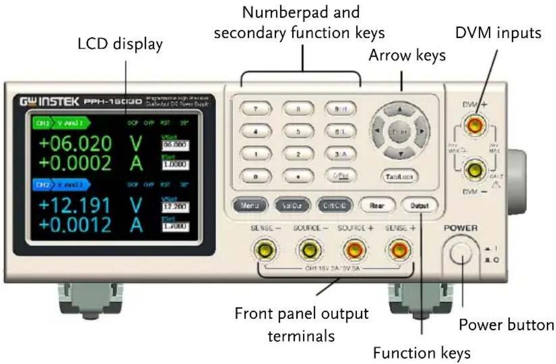
Front Panel
text_image
LCD display GW INSTEK PPH-1803D Numberpad and secondary function keys Arrow keys DVM inputs CH2 V AND 1 +06.020 V +0.0002 A CH2 V AND 1 +12.191 V +0.0012 A 7 8 9 H 4 5 6 L 1 2 3 A 0 Output Menu VACUR CUTCUE Rear Output SENSE - SOURCE - SOURCE + SENSE + GH 16V 3A 5V 5A Power button Function keys Front panel output terminalsDisplay
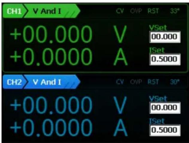
Display Interface
text_image
CH1 V And I CV OVP RST 33" +00.000 V VSet +0.0000 A ISet 0.5000 CH2 V And I CV OVP RST 30" +00.000 V VSet +0.0000 A ISet 0.5000Voltmeter Indicators
Displays the output voltage with up to 5 digits of resolution. The default units are Volts (V).
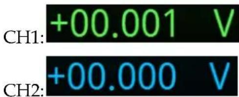
text_image
CH1: +00.001 V CH2: +00.000 VAmmeter Indicator Displays the output current with up to 5 digits of resolution, depending on the current range (CH1:5A or 10A /500mA/5mA/AUTO; PPH-1503D:CH2:1.5A/5mA/AUTO; PPH-1506D/1510D:CH2:3.0A/5mA/AUTO). The current range is selectable between A and mA.
| CH1: 5A /10A | +0.0005 A |
| 500mA | +000.00 mA |
| 5mA | +0.0010 mA |
| CH2: 1.5A/3.0A | +0.0000 A |
| 5mA | +0.0004 mA |
| Auto | -0.0001 mA |
Setting Display
Displays the voltage and current settings.
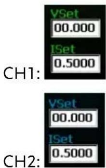
text_image
VSet 00.000 ISet 0.5000 CH1: VSet 00.000 ISet 0.5000 CH2:Parameter Settings Display
Displays the relevant parameter settings. For details on setting parameters, see page 29. The following figure shows the basic power source for both channels (V AND I)
CH1
| List Setting | |||
| IntRate: | 1.00PLC | AverRead: | 1 |
| CurrRange: | 5mA | LimitMode: | Limit |
| RelayControl: | Zero | O.V.P: | 10.00V,Off |
| Resistance: | 0.000ohm | ||
CH2
| List Setting | |||
| IntRate: | 1.00PLC | AverRead: | 1 |
| CurrRange: | Auto | LimitMode: | Limit |
| RelayControl: | Zero | O.V.P: | 10.00V,Off |
Status Display
Display the current status of the instrument.
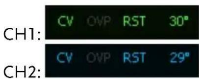
text_image
CH1: CV OVP RST 30° CH2: CV OVP RST 29°Function Display
Displays the unit functions. There four functions:
Basic power supply function (V AND I), Pulse current meter function (PULSE), Long integration current measurement function (LONG INT), Digital Voltmeter function (DVM)(The function only for CH2).
The basic power supply function is shown below.


Function Keys
Menu key

Menu key to enter or exit from system settings.
| Voltage and Current Setting key |  | Voltage and Current setting toggle switch. See page 36 for operation details. |
| CH1/CH2 Toggle Switch |  | CH1 and CH2 setting toggle switch. See page 37 for operation details. |
| CH1 Front and Rear output toggle key |  | Front and rear output toggle switch. The key will be lit when the output is set to the rear outputs. |
Rear panel output:  | ||
| Output key |  | The Output key turns the output on or off. The Output key will light up when the output is on. It has no affect when DVM is activated. |
| On: Output Output | ||
| Tab /LOCK key |  | The Tab key is used to toggle between various parameters. The Lock key is used to disable all the panel keys except for the Output key. Pressing the Lock key for at least 2 seconds will turn the panel lock on or off. The Lock key can also be used to exit from remote control mode. When the panel lock is active the Lock key will light up. |
| Locked: Lock Lock |
Number pad

text_image
7 8 9/H 4 5 6/L 1 2 3/A 0 • C/Picta. The number pad is used to enter various parameters and values. The Clear key can be used to clear set parameters. Pressing the C/Pict key for at least 2 seconds will take a screenshot.
b. H/ L/ A Pulse current measurement shortcut keys. These short cut keys only work in the Pulse current measurement main menu.
H: High measurement mode
L: Low measurement mode
A: Average measurement mode
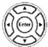
Directional keys and Enter key
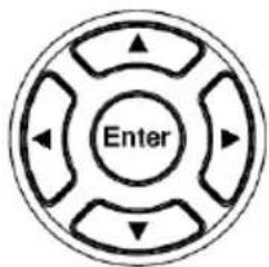
text_image
EnterThe directional keys are used for parameter and menu selection as well for fine adjustment of the current/voltage settings.
The Enter key is used to confirm the selection of any settings or parameters and to exit after a setting is complete.
Power Button

Turns the power on or off.
On: ▲ Off: ■
Terminals
Output Terminals (SOURCE)

Source terminals for the front panel CH1 output.
Voltage Feedback Terminals (SENSE)

Sense terminals for the front panel CH1 output.
Voltmeter Terminals (DVM)
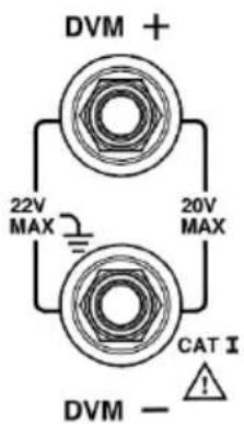
text_image
DVM + 22V MAX 20V MAX CAT I DVM -!Digital voltmeter input terminals.
Rear Panel
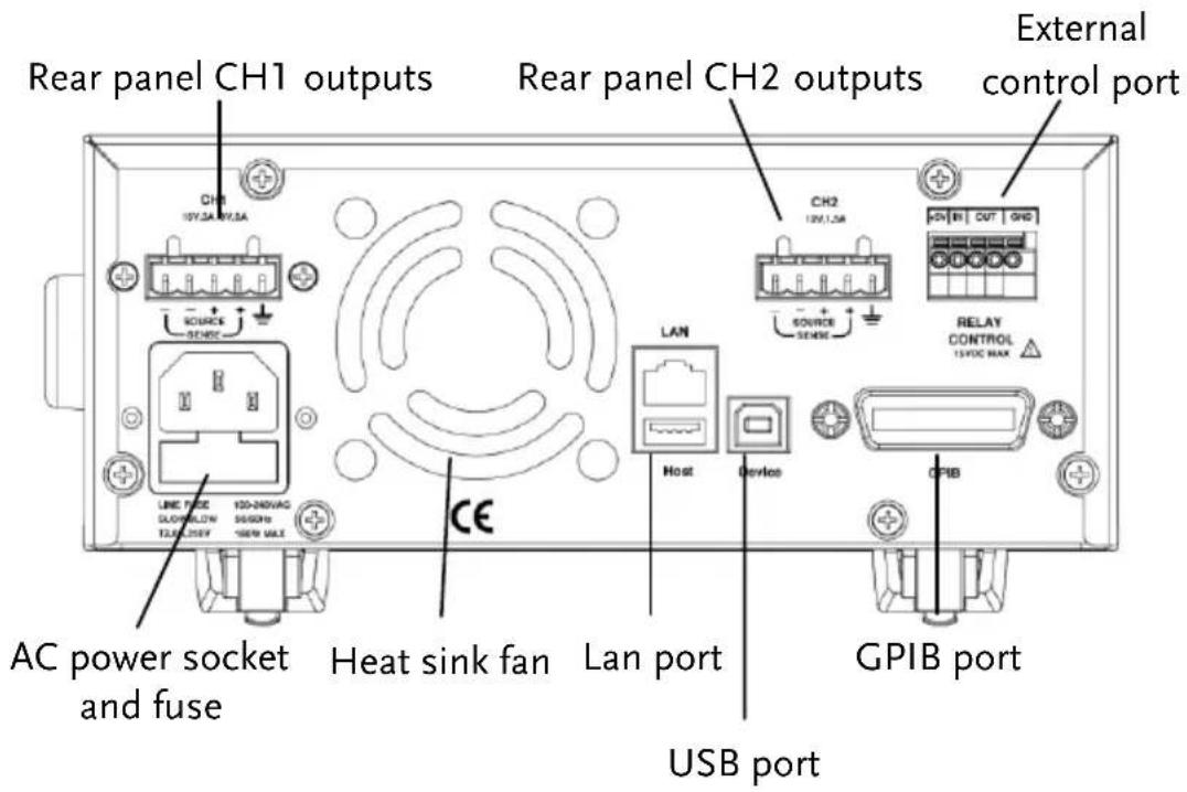
text_image
Rear panel CH1 outputs Rear panel CH2 outputs External control port CH1 10V,3A 9V,5A CH2 10V,1,5A SOURCE SENSE RELAY CONTROL 15VDC MAX LAN Host Device CPB USB port AC power socket and fuse Heat sink fan LAN port GPIB portTerminals
AC input socket and line fuse
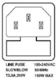
text_image
LINE FUSE 100-240VAC SLOW/BLOW 50/60Hz T2.0A,250V 180W MAXThe AC input accepts 100 to 240 ± 10% VAC. The frequency is 50Hz / 60Hz .
Fuse: 2.0A PPH-1503D )
/2.5A PPH-1506D/1510D
slow-blow type See page 142 for details.
USB port

USB device port for remote control. See page 79 for details.
GPIB port
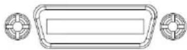
GPIB slave port for remote control. Abides to IEEE488.2 (SCPI) protocol. See page 80 for details.
LAN & Host port
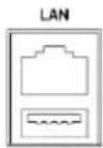
Host
LAN and USB Host port for remote control. See page 82 for LAN setting and operation details. See page 74 for details of USB Host setting and operation.
CH1 rear panel output interface
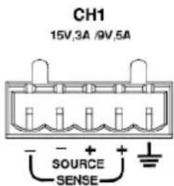
text_image
CH1 15V,3A /9V,5A SOURCE SENSEA total of 5 ports: 1 positive output terminal, 1 negative output terminal, a Sense+ terminal, a Sense- terminal and a ground terminal. Refer to the printed label under the terminals for the specific order of the terminals.
CH2 output interface
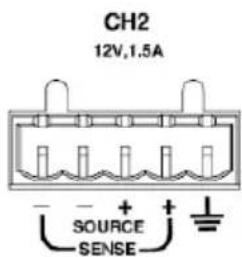
text_image
CH2 12V,1.5A SOURCE SENSEA total of 5 ports: 1 positive output terminal, 1 negative output terminal, a Sense+ terminal, a Sense- terminal and a ground terminal. Refer to the printed label under the terminals for the specific order of the terminals.
Relay control interface
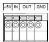
RELAY CONTROL 15VDC MAX
A total of 5 ports: A +5V input terminal, a ground terminal, a logic level input terminal and 2 CH1/CH2 terminals for relay control. See page 59 for relay control details.
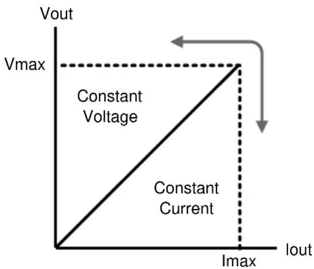
Constant Voltage/Constant Current Crossover Characteristics
| Background | The unit will switch automatically between constant voltage and constant current according to changes in the load. |
| CV mode | When the load current is less than the current setting, the unit operates in constant voltage mode, changing the current level according to the load but maintaining the set voltage level until the current reaches the set current level. The status indicator will show CV on the LCD when in CV mode. |
| Constant Current Mode | When the output current reaches the set current level, the unit switches operation to constant current mode. The status indicator will show CC on the LCD display. In CC mode, the current level is maintained and the voltage level is limited to less than the set voltage level to limit the output power from an overload. When the current drops below the set current level, the unit will revert back to CV mode. |
Diagram
text_image
Vout Vmax Constant Voltage Constant Current Imax IoutGETTING STARTED
This chapter describes the start up procedures and the preparation that is necessary before operating the power supply.
Start Up
Checking the AC Voltage
Before the power is turned on, confirm that the input power supply meets the following conditions: 100-240VAC ±10%, 50Hz/60Hz
| LINE FUSE | 100-240VAC |
| SLOWBLOW | 50/60Hz |
| T2,0A,250V | 160W MAX |
Connecting the AC power cord
The fuse is a 2.0A (PPH-1503D) /2.5A (PPH-1506D/1510D) slow-blow fuse. Confirm that the fuse is of the correct type and rating before connecting the power cord.
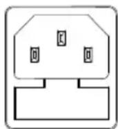
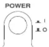
Turning the power on
Press the power button. The LCD will display the line frequency of the AC power supply.

Turning the power off
To turn the power off, press the power button again.
Load and DVM Connection
| Recommended Cables | Model | Specification | Usage |
| GTL-207A | 1kV | Front panel DVM input | |
| GTL-204A | 10A | Front panel Source terminal | |
| GTL-203A | 3A | Front panel Sense terminal | |
| Front panel wiring | Use the GTL-204A cables for the front panel source connections. |  | |
| Use the GTL-203A cables for the sense connections. |  | ||
| Use the GTL-207A cables for the DVM connections. |  | ||
| Rear panel connections | Insert the wires into the appropriate terminal according to the labels printed under the terminals. |  | |
 Note Note | For safety considerations, please keep in mind that the wiring must be equivalent to the wiring on the front terminals. | ||
Wire Gauge
Load wires must have enough current capacity to minimize cable loss and load line impedance. Voltage drop across a wire should not excess 0.5V. The following list is the wire current rating at 450A/cm2.
| Wire Size(AWG) | Maximum Current (A) |
| 20 | 2.5 |
| 18 | 4 |
| 16 | 6 |
| 14 | 10 |
| 12 | 16 |
Turning the Output On/Off
Panel Operation
Press the Output key to turn the output on. The Output key will light-up when the output is on.

When the output is turned on, pressing the Output key again will turn the output off.
Automatic Output Shut Down
Any of the following actions will cause the output to be automatically shut down:
- Recall the saved setting
- OVP/OTP protection is tripped.
- OCP protection is tripped.
MAIN MENU OVERVIEW
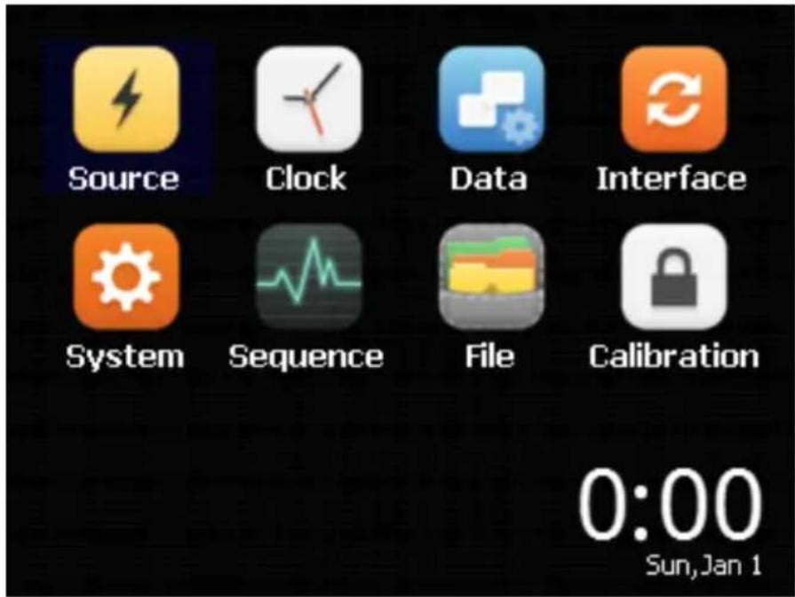
This chapter describes each main function and system setting for this device. The following interface will appear when the Menu key is pressed.
text_image
Source Clock Data Interface System Sequence File Calibration 0:00 Sun, Jan 1Function Description
| Function | Function Description | |
| Source | CH1 / CH2 have basic power functionality. They can display different current values simultaneously.For details, please refer to page 32, in the section, “BASIC OPERATION”. |  |
| Clock | System Real Time Clock SettingFor details, please refer to page 73, in the chapter, “System Real Time Clock Setting”. |  |
| Data | For details about the specific parameters displayed in Save / Recall, please refer to page 64, in the chapter, “SAVE/RECALL”. |  |
| Interface | Remote control setting.For details, please refer to page 79, in the chapter, “REMOTE CONTROL”. |  |
| System | System parameter settings.For details, please refer to page 69, in the chapter, “SYSTEM SETTINGS”. |  |
| Sequence | Output waveform settings.For details, please refer to page 62, in the section, “SEQUENCE Function”. |  |
| File | The System folder is used to import and export data.For details, please refer to page 74, in the section, “Description of using flash driver”. |  |
Calibration
Currently this function is not available.

Date/time
The real-time clock of the device. The date/ time are displayed in this area.

BASIC OPERATION
This chapter describes how to set various functions.
Source Function
text_image
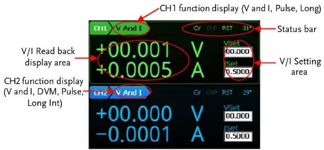
CH1 function display (V and I, Pulse, Long) Status bar CH1 V And I CV OVP RST 31° +00.001 V +0.0005 A V/I Read back display area V/I Setting area CH2 function display (V and I, DVM, Pulse, Long Int) CH2 V And I CV OVP RST 29° +00.000 V -0.0001 A VSet 00.000 ISet 0.5000Note
-
Under the Source interface: Press the Tab key to toggle between "Function Setting", "VSet" and "ISet". CH1 has three functions: V and I / Pulse / Long Int. CH2 has 4 functions: V and I / DVM / Pulse / Long Int. Press the Enter key to enter the corresponding channel's parameter settings. The arrow keys can be used to switch to the secondary parameters. Press the Menu key to exit the parameter settings.
-
When "Function Setting" is selected (displayed font is black), press the arrow keys to switch between the different "Function Setting".
| Description | CH1 and CH2 operate as a basic power supply with the ability to simultaneously display V/I settings and readback values. The output from CH1 can be toggled between the front and rear outputs using the Rear key. When the Rear key is lit, it indicates that the rear panel output is activated and that the front panel output is off. Both outputs can't be activated at the same time. | |
| Parameter Description | IntRate | The data sampling period derived from the number of power line cycles. The setting range is 0.1PLC to 10.00PLC (power line cycles). 1PLC = 16.7ms (60Hz)/20ms (50Hz).*PLC stands for power line cycles. |
| AverRead | Readback refresh rate. This will display the average number count. | |
| CurrRange | The current range selection. Ch1 has four settings: 5A(1503D/1506D) or 10A(1510D), 500mA, 5mA and Auto. CH2 has three settings: 1.5A (1503D) or 3.0A (1506D/1510D), 5mA and Auto.The 5mA range only accepts a current setting 1A or less. If the 5mA range is selected and if the current setting is greater than 1A, the setting value is automatically reduced to 1A. Auto only used for automatic selection of current reading range. | |
LimMode
Current limiting mode. There are 4 settings for the current limiting mode: Limit, Trip, LimitRelay and Trip Relay.
The Limit settings will limit the current. When the current reaches the setting value, the current remains constant, as in CC mode.
The Trip setting will turn the output off when the current limit has been reached.
The Limit Relay setting will assert the relay output control interface low when the output current reaches the limit setting. Otherwise, the relay output interface will be asserted high.
The Trip Relay setting will assert the relay output control interface low when the output current limit is tripped. Otherwise, the relay output interface will be asserted high.
See page 59 for details on the Limit Relay and Trip Relay settings.
| RelayControl | The relay control settings have 2 configurations: Zero/One. | |
| The Zero setting means that the output from the Relay control interface OUT port is low and the external relays will energize. | ||
| The One setting is just the opposite of the Zero setting. | ||
| The user sets the initial state. When the state of the relay control signal changes, the actual state of the relay is displayed. | ||
| Resistance | See page 59 for further details. | |
| The Setting range for battery resistance simulation is 0.000Ω ~ 1.000Ω and the setting resolution is 0.001Ω. | ||
| Note: | This feature is only for CH1. | |
| O.V.P | The overvoltage settings have a setting range of 1.00 ~ 16.00V CH1)/ 1.00 ~ 13.00V (CH2), OFF or AUTO. | |
| RecallSetup | There are 6 sets of save/recall memories.Rst/ SAV0 to SAV4 | |
| Output Range | Voltage | CH1:0.000V~15.000VCH2:0.000V~12.000V |
| Current | CH1:0.0000A~3.0000A (0V~15V)0.0000A~5.0000A (0V~9V)0.0000A~10.0000A (0V~4.5V)(1510D REAR)CH2: 0.0000A~1.5000A (1503D)0.0000A~3.0000A(1506D/1510D) | |
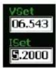
| Parameter Settings(For example CH1) | Voltage | Press the Vol/Cur key andthe voltage setting on theLCD is activated. Thecorresponding number willturn black on whitebackground.(a) Use the number pad (keys:0~9, . , Clear) to set the voltagevalue. Press the Enter key toconfirm.To enter 6.543V: |
(b) Step Setting:
Press the left and right arrow keys () to fine tune the voltage setting at the digit level (The corresponding number will turn black on white background). Press the up and down arrow keys
( ) to adjust the selected digit. Press the
Enter key () to complete the setting.
Current
Press the Vol/Cur key and the current setting on the LCD is activated. The corresponding number will turn black on white background.
(a) Use the number pad (keys: 0\~9, . , Clear) to set the voltage value. Press the Enter key to confirm.
To enter 1.2345A:
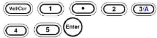
text_image
Vol/Cur 1 • 2 3/A 4 5 Enter(b) Step Setting:
Press the left and right
arrow keys () to fine tune the voltage setting at the digit level (The corresponding number will turn black on white background). Press the up and down

arrow keys () to adjust the selected digit. Press the Enter
Enter key () to confirm the setting.
Note: “Vol / Cur” key is used for only switching voltage and current settings.
IntRate Press the Enter key to bring up the CH1 parameter setting bar. The default setting is IntRate. Use the Enter key to set the parameters. Use the numeric keypad to enter parameters. Press the Enter key again to confirm the setting. The parameter range is from 0.01 to 10.00PCL. Press the Arrow keys to set the other parameters for the setting.
| AverRead | Press the Arrow keys to toggle to AverRead item. Press the Enter key. Use the numeric keypad to enter desired parameters. Press the Enter key to confirm the setting. The parameter range is from 1 to 10 samples. Press the Arrow keys to select the other parameters for the setting. |
| CurrRange | Press the Arrow keys to toggle to CurrRange item. Press the Enter key. Use the up and down arrow keys to select the desired current range. Press the Enter key again to confirm the setting. Press the Arrow keys to select the other parameters for the setting. |
| LimMode | Press the Arrow keys to toggle to LimitMode. Press the Enter key. Press the up and down arrow keys to select the Current Lim mode. Press the Enter key to confirm the setting. Press the Arrow keys to select the other parameters for the setting. |
| RelayControl | Press the Arrow keys to toggle to RelayControl. Press the Enter key. Press the up and down arrow keys to set the desired initial state of relay control. Press the Enter key again to confirm the setting. Press the Arrow keys to select the other parameters for the setting. |
| Resistance | Press the Arrow keys to toggle to Resistance. Press the Enter key. Use the numeric keys to enter parameters (Range: 0.000 to 1.000 Ω). Press the Enter key again. Press the Arrow keys to select the other parameters for the setting.This feature is only for CH1. |
| O.V.P | Press the Arrow keys to select O.V.P. Press the Enter key. Press the down arrow key to select the desired OVP State. There are three states: Off / On / Auto. If the On state is selected, you will need to enter the OVP value. Use numeric keypad to set the parameters. The input parameter range is from 01.00 to 16.00V (CH1)/1.00 to 13.00V (CH2). There is no need to set the OVP value for both the Off and Auto states.When Auto is selected, the OVP function will activate if the output value is higher than the setting value by 0.8V.When connecting with four wires, if any of the source wires disconnects from the load, the OVP function will be activated automatically (i.e., output open circuit protection is activated) |

Note
-
After the parameter settings are complete, press the Menu key to return to the display interface.
-
The Clear key can't be used to clear numbers that have already been entered. It is necessary to set the number again.
-
All numerical parameters can be set by entering the parameter values with the number pad or by using stepped input values.
Operation
REAR / FRONT
After setting all the parameters, press the Rear key to toggle the output between the front and rear terminals for CH1. When the Rear key is lit, it indicates that the rear panel output is activated for CH1. When the Rear key is not lit, it indicates that the front panel output for CH1 is activated.
Output
Press the Output key to turn the output on. When the output is on, the Output key will light up. When the output is off, the Output key will not be lit.
Status Description
CV/CC
CV appears in green (CH1) or in blue (CH2)

CC appears in red

O.V.P
OVP will appear in green (CH1) or in blue (CH2) when the OVP has not been tripped.
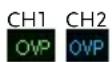
When the OVP has tripped, the output will be turned off and a small prompt window appears.
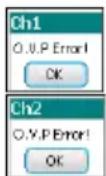
| When the OVP protection has not been activated, it will be greyed-out. | OVP | |
| RST | Displays the power-on state setting. There are 11 states that can be selected: RST and SAVE0 ~ SAVE9. The state can be set with the PowerOnSetup option in System settings. Refer to page 67. | RST |
DVM
| Description | The PPH-1503D/1506D /1510D has a separate digital voltmeter with a measurement range of 0~+20VDC on CH2. | |
| ⚠️Note: DVM and CH2 have a common ground design. So when using the DVM-terminal, it can't be shorted with the negative output of CH2. In addition, when using the voltage meter, the power supply must be properly grounded. | ||
| Parameter Description | Intrate | Sets the reading rate of DVM measurements based on the number of PLCs. The setting range is: 0.1PLC to 10.1PLC=16.7ms(60Hz)/20ms(50Hz).This parameter is shared with "V and I" of CH2.*PLC stands for Power Line Cycle |
| AverRead | Normally the unit will display measurement results onto the screen as soon as they are captured.However when more stable results are needed, averaging can be used. The AverRead function collects several samples of data and then performs an averaging operation on the data before displaying the averaged result on the screen.This parameter is shared with "V and | |
| I" of CH2. | ||
| Parameter Settings | IntRate | Press Enter key to bring up the CH2 parameter setting column. The default setting is IntRate. Press the Enter key. Use numeric keypad to set the parameters (Range: 0.01 to 10.00). Press the Enter key again. Press the Arrow keys to select the other parameter for settings |
| AverRead | Press the Arrow keys to select AverRead item. Press the Enter key. Use numeric keypad to set the parameters (Range: 1 to 10). Press the Enter key again. Press the Tab key to select the other parameter for settings. | |
| Operation | Press CH1 / CH2 key to switch to the CH2 setting. Press the Tab key to switch to the function selection mode (V and I is changed from [CH2] to): Press the right arrow key to go to DVM mode (L) | |
| After switching to the DVM mode, the device is synchronized to start measuring. When voltage is measured, it doesn't affect the operation of the power supply. The output can be turned on or off by pressing the Output button. | ||
Connection
For the connection details for the front and rear terminals, please page 26.
Pulse Current Measurement
Description
Changes in the load current allow us to measure the pulse current.
There are three ways that pulse current can be measured:
- Measuring the peak current over a single cycle (High Measurement).
- Measuring the trough current over a single cycle (Low Measurement).
- Measuring the average current over a single cycle (Average Measurement).
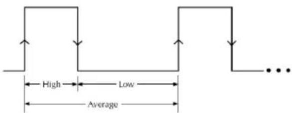
text_image
High Low AverageThe high and average measurements are triggered by the rising edge of the pulse current are performed for the time specified for the measurement.
Low measurement is triggered by the falling edge of the pulse current.
Note: Pulse current measurement is only valid up to 5A or 10A (CH1) and 1.5A or 3.0A (CH2).
Parameter Description
IntTime
- Integration Time.
- The integration measurement time can be set to automatic or to one of the manual settings (High Time, Low Time and Aver Time).
- When the integration measurement time is set to
automatic mode, the system will measure the peaks and troughs of the pulse current and will automatically set an appropriate integration time. The average integration time is the time of all the accumulated peaks and troughs. After the setting the integration time to automatic, the setting will apply to all subsequent pulse measurements, unless the automatic integration mode is applied again or the integration time is manually set. The automatic Integration time can automatically detect pulses in the 80us to 833ms range.
- The manual time range setting is 33us to 833333us. The default units are in microseconds (us).

IntTime setting automatically becomes 33.3 microseconds (us) in mode (Pulse current digitization)
For details, please refer to page 109
TrigDelay
- Trigger Delay
- When a pulse is detected, there will be a 25us code execution delay time. The trigger delay settings are used to filter out the current overshoot. Measurement will begin from after the trigger delay time. The trigger delay setting range is: 0\~0.10000s, with a resolution of 0.00001s. The setting units are in seconds.
| Note | The setting range for TrigDelay is 0~5 sec.(s)in mode (Pulse current digitization) For details, please refer to page 112 | |
| AverRead | ·Average Reading Count: Reads back the average number of displayed values.·This parameter is only applicable for pulse current measurement. The average number range can set from 1 ~ 100 with a resolution of 1. | |
| Note | The setting range for AverRead is 1 ~ 5000 with a resolution of 1 (Pulse current digitization). For details, please refer to page 108 | |
| Trig Level | ·Trigger Level.·To avoid false pulse measurements, the trigger level can be set close to the current amplitude. All noise and transient currents that are below the trigger level will be ignored. The trigger level has a setting range of 0~5A (CH1), 0~1.5A or 0~3.0A (CH2) with a resolution of 5mA. The setting unit for the trigger level is in amps (A). This setting is only valid for pulse measurements. | |
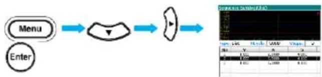
| Parameter Settings | IntTime | Press the Enter key to enter the Pulse current measurement menu. The IntTime setting is the default setting when you first enter the IntTime menu. Press Enter key to select the desired setting. Press the down arrow key to set the type of |
Integration Time. High Time, Low Time and AverTime options are available for selection. Press the up arrow key to decide to set the integration time automatically or manually set. When manually setting is select, use the numbic keypad to directly select a time setting. Press Enter key to complete the setting.
Example:
Low Time 66us: Enter the pulse current measurement menu.
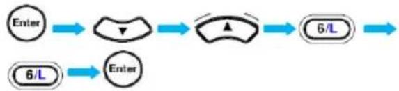
flowchart
graph LR
    A["Enter"] --> B["△"]
    B --> C["▲"]
    C --> D["6/L"]
    E["6/L"] --> F["Enter"]
The time range can be set between 33us and 833333us. The setting units are in microseconds (us).
TrigDelay
Press the Arrow keys to select TrigDelay. Press the Enter key. Use numeric keypad to set the parameters. Press the Enter key again.
The TrigDelay has a settable range of 0\~0.10000. The setting units are in seconds (s).
| TrigLevel | Use the Arrow keys to select TrigLevel. Press the Enter key. Use numeric keypad to set the parameters. Press the Enter key again.The TrigLevel parameter has a settable range of 0~5.000A (CH1), 0~1.500A or 0~3.000A (CH2). The setting units are in amperes (A). | |
| AverRead | Use the Arrow keys to select AverRead. Press the Enter key. Use numeric keypad to set the parameters. Press the Enter key again.The AverRead setting has a settable range of 1~00. | |
| Panel Operation | Output | Press the Output key.When the Output key is lit, pulse current measurement is active.When no pulse current is detected, NO PULSE will be displayed in green on the LCD screen. The unit will wait until the next pulse is detected (CH1 is used as an example here).  |
The measurement settings can be edited during measurement. The H, L, A keys on the keypad can be used to perform fast-switching between measurement modes.

flowchart
graph LR
    A["9/H"] --> B["HIGH"]
    C["6/L"] --> D["LOW"]
    E["3/A"] --> F["AVER"]
Long integration
Description
The long current integration measurement function measures the mean (average) current over a single or multiple current pulses. The long integration time period must be a full period or integer multiples of a complete period of the measured pulse current. The Long integration measurement calculates the whole integration time as an integer number of integration cycles. An integration cycle is the line cycle period plus the data processing time.
For example, if the line frequency is 60Hz, then a single integration cycle is 16.7mS, if the frequency is 50Hz, then a single integration cycle is must be 20mS. Long integration is one of the methods to extend A/D circuits to exceed beyond their maximum integration time. The A /D conversion circuits can measure a pulse of up to 833 ms. Long integration measurement extends the A/D integration time to achieve a longer pulse measurement. This can extend the measurement time for long integration to a maximum of 60S.
Note: When this feature is used, the current range is set to 5A (CH1 with PPH-1503D/1506D), 10.0A (CH1 with PPH-1510D).1.5A (CH2 with PPH-1503D), 3.0A (CH2 with PPH-1506D/1510D).
Parameter
Description
IntTime
- Integration time
- The integration time can be set manually or automatically by the operator. For manual settings, the integration time can be set to a maximum of 60 seconds. For a line frequency of 60Hz the minimum integration time is 850ms with a step resolution of 16.7mS. For a line frequency of 50Hz, the minimum integration time is 840ms with a step resolution of 20ms.
- When the integration time is set to Auto Time, the system will automatically measure the time between two adjacent rising edges and an appropriate integration time is set for the peak and trough. If there are more than two pulses, the integration time must be set manually.
TrigEdge
- Trigger edge
- Pulse edges are used to trigger long integration measurement.
Regardless of whether a rising or falling edge is used as a trigger, a pulse must first be detected before measurement can start.
Measurement can also start without an edge trigger. When TrigOnNeither is selected, measurement starts as soon as the output is turned on.
Trig Level
- Trigger level.
- When the rising or falling edge trigger is selected for long integration current measurement, a pulse must first be detected. The trigger level refers to minimum pulse level required for a pulse to be detected. For example if the trigger level is set to 2A, pulses that are ≤2A will be detected. Pulses <2A will be ignored. The trigger level range is 0\~5A (CH1), 0\~1.5A or 0\~3.0A (CH2). This setting only applies to long current integration measurements.
Timeout
- Pulse timeout
- When long integration measurement is selected and the unit doesn't detect a pulse after a certain amount of time (pulse timeout time), the "No Pulse" message will be displayed on the LCD. This function is only applicable if rising or falling edge is selected as the edge trigger; the Trig OnNeither trigger setting has no pulse timeout. The pulse timeout has a range of 1\~63 seconds.
Parameter Settings
IntTime
Press the Enter key to enter the Long integration measurement menu. The IntTime setting is the default setting when you first enter the IntTime menu. Press Enter key to select the desired setting. Press the up arrow key to decide to set the integration time automatically or manually set. When manually setting is select, use the
| numeric keypad to directly select a time setting. Press Enter key to complete the setting. | ||
| For manually set integration times, if the set time is not an integer multiple of the integration cycle time, the system will automatically round down to closest maximum integer multiple that can be set. The time range is 850ms to 60s (50Hz) and 840ms to 60s (60Hz). The default unit is seconds (s). | ||
| TrigEdge | Use the Arrow keys to select TrigEdge. Press the Enter key. Use the up and down arrow keys to select the type of trigger. Press the Enter key again. The interface will display the selected trigger type. | |
| TrigLevel | Press the Arrow key to select TrigLevel. Press the Enter key. Use numeric keypad to directly set the parameters. Press the Enter key again. The trigger level setting range is 0~5A (CH1), 0~1.5A or 0~3.0A (CH2). The default unit is amps (A.) | |
| Timeout | Press the Arrow key to select Timeout. Press the Enter key. Use numeric keypad to directly set the parameters. Press the Enter key again. The time range is 1~63s. The default unit is seconds (s). | |
| Operation | Output | Press the Output key. When the Output key is lit, pulse current measurement is active. |
When no pulse current is detected, NO PULSE will be displayed in green (CH1) or in blue (CH2) on the LCD screen. The unit will wait until the next pulse is detected.

Battery simulation function
Function
Description
The function can be seen as being equivalent to power source U in series with resistor R. The equivalent circuit model diagram is shown below:

text_image
R U UoThe unit has an internal series resistor that can set the resistance of the circuit to simulate the output voltage of a battery.
Output voltage
When CH1 is outputting current, the output voltage will decrease when the output current increases.
When CH1 is used as a sink, the output voltage will increase with an increase in output current.
Setting the internal resistance
The internal resistance setting range is 0.000 to 1.000 ohms. For detailed operation, please refer to page 40.
Current Sink Function
Function
Description
When the test circuit is an active circuit, and the manifested voltage in the test circuit is greater than the output voltage of the power supply, the power supply will automatically disipate current from the external power supply. When this function is in the normal operating state, the power supply outputs the setting voltage, which is equivalent to a constant voltage load rather than constant current load.
The current disipation from the power supply output flows from the positive terminal out to the negative terminal. The amount of current sunk is not controlled from the power supply.
Connection
Connect the positive terminal of the external power supply to the positive terminal on the high-speed power supply. Connect the negative terminal of the external power supply to the negative terminal on the high-speed power supply.

text_image
PPH-1503D + 3.0V - I sink R + 4.2V - VConditions
To protect the high-speed power supply when operating as a current sink, the following two conditions must be met:
- Ensure that the voltage of the external power supply is greater than the output of the high-speed power supply voltage by 0.3V\~2.5V. The voltage difference depends on the high-speed power supply voltage output and the load conditions.
- To ensure that the power supply output voltage is within certain range, the current draw must be less than the limit value. See the formula in the Table below for the details.
CH1: To ensure that the high-speed power supply output voltage is within the range of 0\~4V, the current draw cannot exceed 3.5A. For output voltages between 4V\~15V, the current draw must be reduced by 0.25A for each 1V increase. See the formula in the table below for the details.
| High-speed Power Supply Output Voltage | Maximum Dissipation Current |
| 0~4V | 3.5A |
| 4V~15V | 3.5A-(0.25A/V)*(Vset-4V) |
CH2: To ensure that the high-speed power supply output voltage is within the range of 0\~5V, the current draw cannot exceed 2A(or 3A). For output voltages between 5V\~15V, the current draw must be reduced by 0.1A(or 0.25A) for each 1V increase. See the formula in the table below for the details.
| High-speed Power Supply Output Voltage | Maximum Dissipation Current | |
| 0~5V | 1503D | 2.0A |
| 1506D/1510D | 3.0A | |
| 5V~12V | PPH-1503D | 2.0A-(0.1A/V)*(Vset-5V) |
| 1506D/1510D | 3.0A-(0.25A/V)*(Vset-5V) | |
External Relay Control
Function
Description
When the Relay control feature is turned on, it is synced to the current limit of the power supply. The external relay control is divided into two different types, a limit relay and a trip relay.
The limit relay is used in conjunction with CC mode. When the constant current setting value is reached, the relay control signal will go high and will return back to the low level when the current level goes back below the constant current setting.
The trigger relay is used in conjunction with CC mode. When the constant current setting value is reached, the relay control signal will go high and the output is disabled. When the output goes back on and the current is less than the current setting value, the relay control signal will back to the low level.
Rear Panel
Control Interface
The rear panel control interface has five terminals, +5V, IN (The state of the Trip or Trip Relay output is used as the signal input), OUT (CH1 & CH2 controls signal output) and GND (connected to the chassis ground or earth ground), respectively.
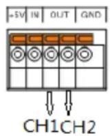
Wiring Method
A thin screwdriver or similar tool will need to be inserted into the release mechanism (highlighted in orange in the figure above) to open the terminals. Insert an exposed wire into the terminal and release the mechanism to lock the wire into place.
Schematic Diagram for Relay Control
Limit Relay:

line
| Time | Current | Relay | |------|---------|-------| | 0 | Low | Off | | 1 | Low | Off | | 2 | Low | On | | 3 | Low | On | | 4 | Low | On | | 5 | Low | Off | | 6 | Low | Off | | 7 | Low | Off | | 8 | Low | Off | | 9 | Low | Off | | 10 | Low | Off | | 11 | Low | Off | | 12 | Low | Off | | 13 | Low | Off | | 14 | Low | Off | | 15 | Low | Off | | 16 | Low | Off | | 17 | Low | Off | | 18 | Low | Off | | 19 | Low | Off | | 20 | Low | Off | | 21 | Low | Off | | 22 | Low | Off | | 23 | Low | Off | | 24 | Low | Off | | 25 | Low | Off | | 26 | Low | Off | | 27 | Low | Off | | 28 | Low | Off | | 29 | Low | Off | | 30 | Low | Off | | 31 | Low | Off | | 32 | Low | Off | | 33 | Low | Off | | 34 | Low | Off | | 35 | Low | Off | | 36 | Low | Off | | 37 | Low | Off | | 38 | Low | Off | | 39 | Low | Off | | 40 | Low | Off | | 41 | Low | Off | | 42 | Low | Off | | 43 | Low | Off | | 44 | Low | Off | | 45 | Low | Off | | 46 | Low | Off | | 47 | Low | Off | | 48 | Low | Off | | 49 | Low | Off | | 50 | Low | Off | | 51 | Low | Off | | 52 | Low | Off | | 53 | Low | Off | | 54 | Low | Off | | 55 | Low | Off | | 56 | Low | Off | | 57 | Low | Off | | 58 | Low | Off | | 59 | Low | Off | | 60 | Low | Off | | 61 | Low | Off | | 62 | Low | Off | | 63 | Low | Off | | 64 | Low | Off | | 65 | Low | Off | | 66 | Low | Off | | 67 | Low | Off | | 68 | Low | Off | | 69 | Low | Off | | 70 | Low | Off | | 71 | Low | Off | | 72 | Low | Off | | 73 | Low | Off | | 74 | Low | Off | | 75 | Low | Off | | 76 | Low | Off | | 77 | Low | Off | | 78 | Low | Off | | 79 | Low | Off | | 80 | Low | Off | | 81 | Low | Off | | 82 | Low | Off | | 83 | Low | Off | | 84 | Low | Off | | 85 | Low | Off | | 86 | Low | Off | | 87 | Low | Off | | 88 | Low | Off | | 89 | Low | Off | | 90 | Low | Off | | 91 | Low | Off | | 92 | Low | Off | | 93 | Low | Off | | 94 | Low | Off | | 95 | Low | Off | | 96 | Low | Off | | 97 | Low | Off | | 98 | Low | Off | | 99 | Low | Off | | 100 | Low | Off | | Note: The 'Limit setting' label indicates the current value in the chart. The 'Relay' label indicates the relay state. The 'off' label indicates the off state. The 'on' label indicates the on state. The 'off' label indicates the off state. The 'on' label indicates the relay state. The 'off' label indicates the relay state. The 'off' label indicates the off state. The 'on' label indicates the relay state. The 'off' label indicates the relay state. The 'on' label indicates the off state. The 'off' label indicates the relay state. The 'on' label indicates the relay state. The 'off' label indicates the off state. The 'on' label indicates the relay state. The 'off' label indicates the relay state. The 'on' label indicates the relay state. The 'off' label indicates the off state. The 'on' label indicates the relay state. The 'off' label indicates the relay state. The 'on' label indicates the relay state. The 'off' label indicates the off state. The 'on' label indicates the relay state. The 'off' label indicates the relay state. The 'on' label indicates the RF system. The 'off' label indicates the RF system. The 'on' label indicates the RF system. The 'off' label indicates the RF system. The 'on' label indicates the RF system. The 'off' label indicates the RF system. The 'on' label indicates the RF system. The 'off' label indicates the RF system. The 'on' label indicates the RF system. The 'off' label indicates the RF system. The 'on' label indicates the RF system. The 'off' label indicates the RF System. The 'on' label indicates the RF System. The 'off' Label indicates the RF System. The 'on' Label indicates the RF System. The 'off' Label indicates the RF System. The 'on' Label indicates the RF System. The 'off' Label indicates the RF System. The 'on' Label indicates the RF System. The 'off' Label indicates the RF System. The 'on' Label indicates the RF System. The 'off' Label indicates the RF System. The 'on' Label indicates the RF System. The 'off' Label indicates the RF System. The 'on' Labeled Label indicates the RF System, whereas the RF System Labeled Label indicates the RF System Labeled Label, which is not explicitly labeled in the code but referenced from the chart.Trip Relay:
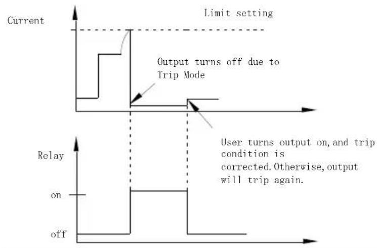
line
| Condition | Output Turn Off | Relay State | | ----------------- | --------------- | ----------- | | Limit setting | Yes | On | | Limit setting | No | Off | | Output turns off | Yes | On | | Output turns off | No | Off | | User turns output on, trip condition is corrected. Otherwise, output will trip again. | Yes | On | | User turns output on, trip condition is corrected. Otherwise, output will trip again. | No | Off |External Relay Connection
There are two ways to connect an external relay to the unit:
- Using the +5VDC relay output to drive an external relay. Ensure the current doesn't exceed 150mA.

text_image
Power Supply Relay Control +5VDC Internal Source +5VDC ±5% OUT OUT IN GND Relay Protection DiodeWarning: Do not short the 5VDC terminal to the chassis, earth or to the control port GND, otherwise it may damage the unit.
- Using an external power source to drive the external relay. The voltage of the source cannot exceed 15V and the current cannot exceed 150mA.
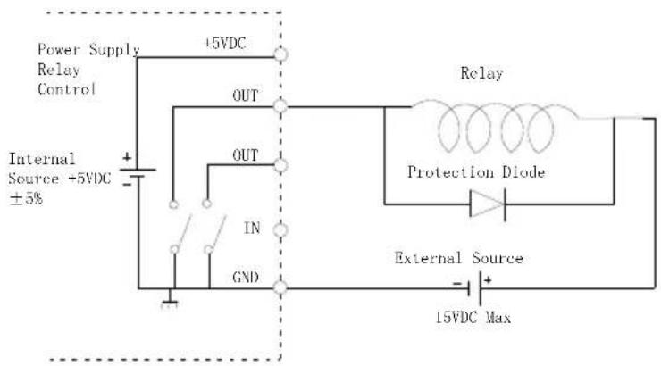
text_image
Power Supply Relay Control +5VDC Internal Source +5VDC ±5% OUT OUT IN GND Relay Protection Diode External Source -15VDC MaxSequence Function
Description
This function can be used for practical applications when different voltage waveforms are required to be output. Users can edit the output waveform according to their needs. The amplitude range of the output waveform is the output voltage range of power supply. The setting range for output waveform duration is 0.001s \~ 3600s and the resolution is 0.001s.

Note: This feature is applicable to CH1.
Parameter Overview
NCycle
Cycle number, N represents an infinite loop (Enter digit “0”). 1 represents a 2 cycle period. 2 represents a cycle with 2 periods, and so on. The range is from 0 to 9999.
Steps
Sets the number of parameter which can set. The range is 1 to 1,000.
Parameter Setting
NCycle
After entering the Sequence interface, this parameter is selected by default. Use the numeric keys to set parameters directly and then press the Enter key.
Steps
Press the Tab key to select Steps. Press Use numeric keys to set the parameters directly and then press the Enter key.
V/I/T Setting
Press the Tab key to select the Voltage / Current / Time setting area.
| No | V | A | S |
| 1 | 1.000 | 2.0000 | 2.000 |
| 2 | 1.000 | 0.5000 | 0.100 |
| 3 | 1.000 | 0.5000 | 0.100 |
Press the up and down arrow keys to select the desired Step setting. Press the Enter key to input voltage value. Press the right arrow key to input the current value. Press the right arrow key to enter the duration and press the Enter key to complete the Step settings. Press the arrow keys to continue to set other specific parameters for the Steps setting.
Operation
Enter the Sequence interface
flowchart
graph LR
    A["Menu"] --> B["Process Step"]
    B --> C["Output"]
SAVE/RECALL
Description
Five groups of system settings are available. SAV0, SAV1, SAV2, SAV3 & SAV4, respectively.
There are a total of 6 different memory settings that can be recalled: Rst, SAV0, SAV1, SAV2, SAV3 and SAV4.
Parameter data
Listed below are the settings that are available for each group (SAV0 in CH1 is shown as an example).
| Item | Status |
| Voltage: | 0.000 V |
| Current: | 0.5000 A |
| OutputState: | Off |
| DispType: | Actual V and I |
| CurrRange: | 5 A |
| IntRate: | 1.00 PLC |
| AverRead: | 1 |
| O.V.P: | 10.00 V (Off) |
| LlmMode: | Limit |
| RelayControl: | Zero |
| HighTime: | 33 uS |
| LowTime: | 33 uS |
| AverTime: | 33 uS |
| AverRead(P): | 1 |
| TrigDelay: | 0.00000 S |
| TrigLevel(P): | 0.000 A |
| IntTime: | 1.000 S |
| TimeOut: | 16.000 S |
| TrigEdge: | RISING |
| TrigLevel(L): | 0.000 A |
The parameters with parentheses are the ones with a specified function. For example, TrigLevel (P) is the power level setting for pulse measurement.
Operation
Press the Menu key to enter the main menu interface.
Use the right arrow keys to select the Data option.


Press the Enter key to go to the Data menu.
Use the down arrow keys to expand the six sets of options for the selected channel, RST, SAV0, SAV1, SAV2, SAV3 and SAV4, respectively. Press the down arrow key to select the desired save memory. There are five selections: SAV0, SAV1, SAV2, SAV3 and SAV4.
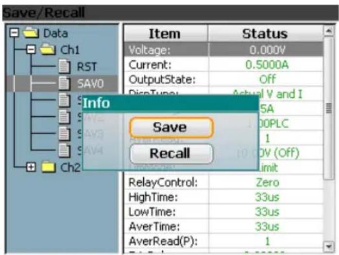
Press the Enter key and the Save/Recall window appears. Press the Tab key to select save or recall. Press the Enter key to complete this step. The Save/Recall selection window is shown as below.


text_image
Save/Recall Data Ch1 RST SAV0 Info Save Recall Item Status Voltage: 0.000V Current: 0.5000A OutputState: Off DipcTuning: Actual V and I 5A 00PLC 1 0V (Off) Limit RelayControl: Zero HighTime: 33us LowTime: 33us AverTime: 33us AverRead(P): 1
Power-on Settings
In the System Setting menu, the interface parameter settings area shows PowOnSetup settings. There are 11 settings to choose from, Rst, SAV0\~SAV4 and SAV5\~SAV9.
The main difference between SAV0\~SAV4 and SAV5\~SAV9 is that SAV0\~SAV4 are user saved settings and don't contain the Power On/Off state (It is always off) while the SAV5\~SAV9 contain the Power On/Off state (it can be on or off).
The relationship between SAV0\~SAV4 and SAV5\~SAV9 is as follows:
SAV0-SAV5
SAV1-SAV6
SAV2-SAV7
SAV3-SAV8
SAV4 SAV9
Restore Factory Default Settings
| Description | The system can restore six sets of settings. The Rst setting is the factory default settings. This setting cannot be modified by the user. |
| Operation | There are two methods to retrieve the factory default settings. Please see the Recall Settings sections for instructions (page 64). |
The Factory Default Settings
| Description | Setting value | Setting item | Setting value |
| Voltage setting | 00.000V | Current range | Auto |
| Current setting | 0.5000A | Integration time ratio | 1.00PLC |
| Output state | Off | Readback display for V and I mode (average value) | 1 |
| Displayed type | Actual V and I | O.V.P Overvoltage Protection | 10.00 (Off) |
| GPIB address | 5 | Limited current mode | Limit |
| GPIB format | Exponential | Relay control | Zero |
| Pulse measurement time | 33us | Readback display for Pulse mode (average value) | 1 |
| Low level measurement time | 33us | Trigger delay | 0.00000s |
| The average measurement time | 33us | Pulse trigger level | 0.000A |
| Long integration time setting | 1.000s | Trigger mode | Rising |
| Overflow time setting | 16.000s | Long integration trigger level | 0.000A |
| Pulse measurement time | High | Digital quantized output mode | Off |
| Pulse time setting | Manual | Long integration time setting | Manual |
| Audible alarm | On | Backlight brightness | High |
| Power-on setting | Rst | Output Mode | REAR |
| MAC physical address | Factory setting | IP address | 172.16.131.170 |
| Subnet mask address | 255.255.255.0 | Gateway Address | 172.16.131.1 |
| DNS server | 172.16.131.1 | IP acquisition mode | Manual |
| Monitoring | On | Host Name | MYHOST |
SYSTEM SETTINGS
System Information
| Description | The System Information menu can be used to view the system information or to perform system operations such as set the buzzer function, backlight display brightness or set to the factory conditions. | |
| System Information Items | System Version | View the system software version. |
| Serial Number | View the machine serial number. | |
| MAC | The physical address of the device. | |
| Firmware | Software version | |
| OS | Operating System | |
| FatFS | File system version | |
Operation
Press the Menu key and press the arrow keys to
select System. Press the Enter key to enter the System Information menu. Press the Tab key to select About item and then press the Enter key to view the system information.
Utility Settings
| Description | There are four utility settings: Remote command data output format, power-on state setting, buzzer settings and backlight brightness settings. | |
| Setting Information | OutputFormat | Remote command data output format |
| PowOnSetup | Power-on state setting | |
| Beep | Sets when the buzzer is turn on. | |
| BackLight | Adjust the LCD brightness. | |
| Output Data Format for remote operation | In the System menu, OutputFormat is the default option. Use the up and down arrow keys to directly set the data format. There are four types of data formats available for selection. Exponential, 2DPS, 3DPS and 4DPS. | |
| Power-on settings operation | In the System menu, press the Tab key to select PowOnSetup. Use the up and down arrow keys to select the initial state when the instrument is powered-on. | |
| Buzzer Operation | In the System menu, press the Tab key to select to select Beep. Use the up and down arrows to directly set the buzzer. | |
| Backlight Brightness Adjustment | In the System menu, press the Tab key to select Backlight. Then use the up and down arrow keys to directly select Backlight brightness. There are three brightness levels: High, Middle, and Low. | |
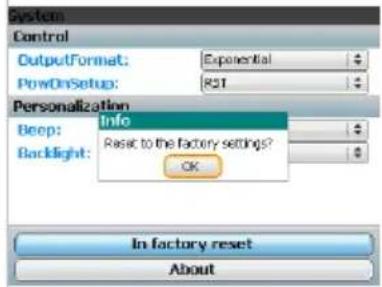
Restore to Factory In the System menu, press Settings the Tab key to select Reset,
the Tab key to select Rese and then press the Enter key. A pop-up window will appear as shown on the right. Press the Enter key to compete this step.
text_image
System Control OutputFormat: Exponential PowerOnSetup: RST Personalization Beep: Info Backlight: Reset to the factory setting? OK In factory reset AboutFirmware Upgrading
| When to Upgrade Firmware | When system is failure, request by customer GW Instek. When the system fails, firmware can requested by GW Instek customers. | |
| Upgrade Requirement | Firmware file | Supplied by GW Instek |
| Flash drive | USB2.0/USB3.0 FAT file system | |
Operation
● Turn off the PPH-1503D/1506D/1510D
- Press and hold the Enter key and then turn on the device at the same time.
- Insert the flash drive within 10 seconds. The system will then be upgraded automatically. The Tab/ Lock, Rear and Output indicators will light up in sequence. Once the LCD screen turns black, the system reboots and completes the system upgrade procedure.
System Real Time Clock Setting
| Description | This setting is used to set the display of the real time clock. |
| Operation | Press the Menu key and press the arrow keys to select icon. Press the Enter key to enter the setting menu. |
| Setting | When you enter the Clock menu, press the Enter key to enter the parameter setting menu. |
| Press the Tab key to select the year, month, date, day, hour and minute. | |
| Press the arrow keys to set the parameters. | |
| After setting all the time parameters, press the Enter key to exit the setting. | |
| Press the Menu key to return to the Menu interface. |
Description of Using Flash Drive
Description
It can be use when upgrading the software upgrades and importing or exporting files.
Please refer to page 72 for upgrading the firmware. Importing and exporting files is mainly used in screenshots and setting the parameter SEQUENCE. Operation step is described as follows:
Operation
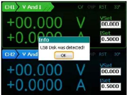
Insert flash driver into the USB Host port. Then the system identifies the flash driver and pops up a confirmation window. Please press Enter key to confirm.
text_image
CH1 V And I +00.000 V +0.000 A CH2 V And Info LSB Disk was detected! OK VSet 00.000 ISet 0.5000 CH2 V And VSet 00.000 ISet 0.5000Screenshot operation
After the system identifies the flash driver, move the device interface to desired interface. Press and hold the C/Pict key and a window showing the screenshots successful will pop up. Press the Enter key to confirm. The screenshot image will be saved to the PPH-1503D(PPH-1506D/1510D) / Snapshot folder by default in the flash driver.


text_image
CH1 V And I +00.000 V +0.0000 A Info Snapshot succeed! OK CH2 V And I +00.000 V +0.0000 A CV OVP RST 32° VSet 00.000 [Set 0.5000] CH2 V And I VSet 00.000 [Set 0.5000]Exporting the Sequence data
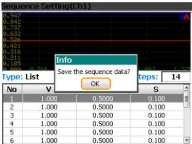
- Saving the Sequence parameter: Enter the Sequence interface and set up the parameters (see 62 for detailed operation). When pressing the Menu key to exit, a window will pop up to ask whether to save the settings. You need to press Enter to confirm, otherwise the save operation will be canceled.

text_image
Sequence Setting(Ch1) 0.947 0.842 0.737 0.632 0.526 0.421 0.316 0.211 0.105 0.088 0.266 Type: List Info Save the sequence data? OK Steps: 14 No V S 1 1.000 0.5000 0.100 2 1.000 0.5000 0.100 3 1.000 0.5000 0.100 4 1.000 0.5000 0.100 5 1.000 0.5000 0.100 6 1.000 0.5000 0.100
2. A. Select the Menu interface
and then press the Enter key to enter the File menu. Press the Enter key to enter the local C: drive (default disk).

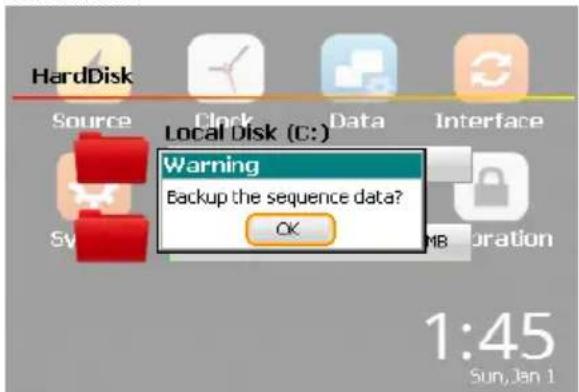
B. Press the up and arrow keys to select the User folder in the C: drive, press the Enter key to enter the folder to browse. Use the arrow keys to select Sequence file. The system will show the Sequence data export confirmation window. Press Enter to confirm.

text_image
HardDisk Source Clock Data Interface Local Disk (C:) Warning Backup the sequence data? OK 1:45 Sun, Jan 1Note: In the flash drive, the default location is in the PPH-1503D(PPH-1506D/1510D) / User folder.
Importing the Sequence data
Use EXCEL to set the Sequence parameters to the following format and save to the flash drive in the computer (*.csv format).
A. Insert the flash drive to the USB Host port on the device.
B. Enter the interface. Press the up and down arrow keys or Tab/Lock key to select Removable Disk (D :). Press the Enter key to confirm and enter the folder to browse.

C. Press the up and down arrow keys to select Sequence data. Press the Enter and a message asking to replace the Sequence data appears. Press the Enter key to confirm.


text_image
HardDisk Source Clock Data Interface Local Disk (C:) Warning Replace the sweep data? OK 2MB 23:51 Sun, Jan 22REMOTE CONTROL
Remote Control
USB
| Description | The PPH-1503D/1506D can be connected via USB using the USB Test & Measurement (TMC) class(Full Speed). |
| Interface | Rear panel USB slave port.  |
| Installing the Driver | Before connecting the unit to the USB port of the PC, Please use “NI Visa” (National Instruments Corporation). Connect a USB cable to send a command. If the connection is successful, the USB will be shown as the interface type on the lower left corner of the LCD display. The front panel keys are automatically locked when the unit is in remote mode. |
| Function Check | Perform the following query:*IDN?The unit will return the manufacturer, model, serial number and software version.GW INSTEK, PPH-1503D, SN: xxxxxxxx, Vx.xx |
| Disabling Remote Control Mode | Send a remote command from the PCLong-press the unlock key on the front panel.Unplug the USB cable from the rear panel. |
 Note Note | USB devices are hot-plug devices. You can directly remove the cable and exit. |
GPIB
| Description | The communication data format, compatibility settings and GPIB address must all be configured before using GPIB remote control. | |
| Interface | Rear panel GPIB port. |  |
| Connection | Connect a GPIB cable to send a command. If the connection is successful, the GPIB will be shown as the interface type on the lower left corner of the LCD display.The front panel keys are automatically locked when the unit is in remote mode. | |
| Communication Data Format | There are four data formats to select from: Exponential, 2DPS, 3DPS and 4DPS. | |
| Set the communication address | Set the communication address for the PC to communicate with. | |
| Steps | A. Press the Menu key to enter the main menu.B. Use the left and right arrow keys to select select C. Press Enter to enter the Interface menu.D. Primary Address is the default Option for GPIB interface. Use the up and down arrow keys to set the port address. | |
| Exiting from Remote Control Mode | Send a remote command from the PCLong-press the unlock key on the front panel.Unplug the USB cable from the rear panel. | |
LAN
| Description | When using the LAN interface a number of settings must be turned on. | |
| IP Mode | The IP address can be configured using either DHCP or Manual IP. Using | |
| Manu IP | A. Press Menu to enter the main menu. | Menu |
| B. Use the left and right arrow keys to select Enter. | Enter | |
| C. Press Enter to enter the Interface menu. | Enter | |
| D. Press the Tab key to select the Ethernet function. | Tab/Lock | |
| E. Use the up and down arrow key to select DHCP or select Manual. | Tab/Lock | |
| F. If the Manual option is selected, press the Tab key to select specific IP parameters. | Tab/Lock | |
| G. Use the number pad and C key to set the specific parameters and values. | C/Shot | |
Parameter Settings:
IP Address: IP address range: 1.0.0.0 to 223.255.255.255 (excluding 127.nnn.nnn.nnn).
Subnet Mask: Subnet Mask Range: 1.0.0.0 to 255.255.255.255.
Gateway: Gateway range: 1.0.0.0 to 223.255.255.255 (excluding 127.nnn.nnn.nnn).
DNS Servers: DNS Server range: 1.0.0.0 to 223.255.255.255 (excluding 127.nnn.nnn.nnn).
VISA Resource name: TCPIPO::172.16.131.170::1026::SOCKET
DHCP
Follow steps A\~F in the previous section
G. Press Enter to select DHCP. The unit will be assigned an IP address, subnet mask, the default gateway and other network parameters from the DHCP server. The corresponding parameters will be shown in the parameter area. Use the arrow keys to view the settings (When an IP address is being assigned, a circular scanning icon will appear).
PC Operation
- Enter the IP address into Microsoft Internet Explorer (IE). After entering the IP address you will be shown the Welcome screen which displays the instrument information. The page also provides three links: Welcome Page, Browser Web Control and View & Modify Configuration (network settings).
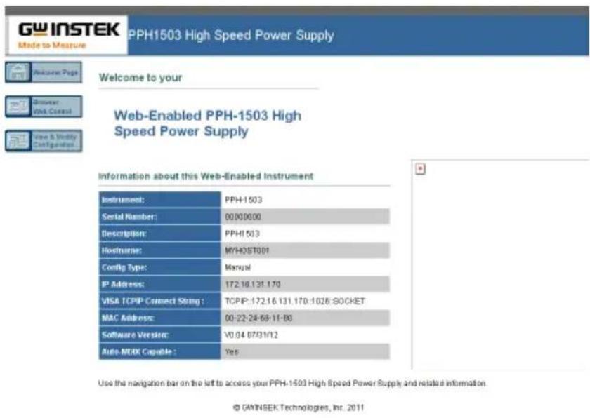
text_image
GW INSTEK Made to Measure PPH1503 High Speed Power Supply Welcome to your Browser: Web Control Web & Modly Configuration Web-Enabled PPH-1503 High Speed Power Supply Information about this Web-Enabled Instrument Instrument: PPH-1503 Serial Number: 00000000 Description: PPHI 503 Hostname: MYHOST001 Config Type: Manual IP Address: 172.16.131.170 VISA TCP/IP Connect String : TCPIP: 172.16.131.170:1026 SOCKET MAC Address: 00-22-24-69-11-80 Software Version: V0.04.07/31/12 Auto-MODI Capable : Yes Use the navigation bar on the left to access your PPH-1503 High Speed Power Supply and related information. © GWINSEK Technologies, Inc. 2011- Click on "Browser Web Control" to execute commands through the browser, as shown below.

text_image
GW INSTEK Made to Measure PPH1503 High Speed Power Supply Welcome Page <|im_start|> Dominant Web Control View & Modify Configuration SCP1: Submit SCP Response:- Press the "View & Modify Configuration" icon to enter the Modify Config menu, as shown below.
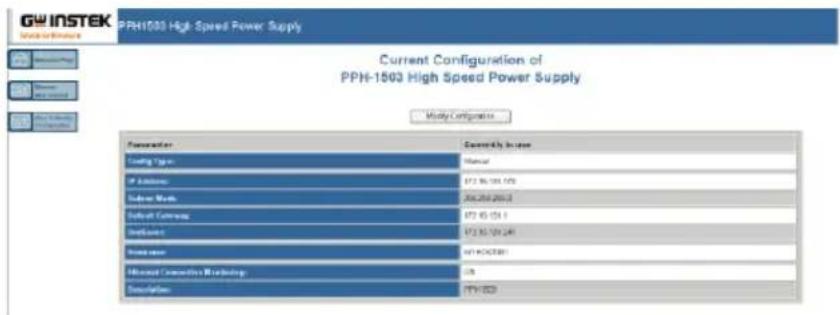
text_image
GW INSTEK PPH-1503 High Speed Power Supply Current Configuration of PPH-1503 High Speed Power Supply Modify Configuration Parameter Coating Type: Manual IP Address: 872 96 101 172 Subway Work: 204 206 207 2 Default Currency: 872 95 151 1 Debitout: 872 95 150 241 Interest rate: MAYA/CCC/BBY Microsoft Commission Marketing: C# Simulation: PYY-003- Click "Modify Config" to enter the network configuration setting menu, as shown below. Use the mouse to click on "Save and Restart" to change the remote settings for the PPH-1503D/1506D/1510D.

text_image
GW INSTEK PPH-1503 High Speed Power Supply Configuring your PPH-1503 High Speed Power Supply Union Data Save and Remove Factory Details Parameters Configuration Value Edit Configuration P Settings (select the minimum amount only for following) Unit Type: Manual C:\COMP\ACMP\Mass P Settings to use 2 equivalents units as a series or service P Options: 172.6.138.179 972.6.138.179 Subunit Work: 266.268.2613 255.268.2613 Default Service: 172.6.138.1 972.6.138.1 Preferences: 172.6.138.28 972.6.138.28 Services: W/40/2000 W/40/2000 Channel: Selective Monitoring: ON P: ON / ON Description: PPH-1503
Note
Click "Undo Edits" to cancel all the edited settings. Click "Factory Defaults" to restore to the factory default settings.
Exiting from Remote Control Mode
- Send a remote command from the PC
- Long-press the unlock key on the front panel.
- Unplug the USB cable from the rear panel.
LAN is running...

Note
Hot-swappable LAN devices can be directly disconnected to exit.
Command Syntax
The commands that are used with the PPH-1503D/1506D/1510D meet IEEE488.2 and SCPI standards.
SCPI Commands Overview SCPI
Command Format
SCPI is an ASCII based command language designed for test and measurement instruments. SCPI commands uses a hierarchical structure (tree system), and is divided into different subsystems. Each subsystem is defined by a different root keyword. Each command consists of a root keyword and one or more hierarchical key words separated by a colon “:” and followed by a parameter. There is always a space between the keywords and the parameters. Any commands followed by a question mark (?) are queries.
For Example:
:SYSTem:BEEPer:STATE {0|1|OFF|ON}
:SYSTem:BEEPer:STATe?
SYSTem is the root level keyword and BEEPer and STATe are the secondary and tertiary level keywords. All levels have a “:” separating each keyword. Parameters are enclosed in “{}”.
The commands SYSTem:BEEPer:STATe has {0 | 1 | OFF | ON} as parameters. The parameters are separated with a space.
SYSTem:BEEPer:STATe? indicates that the command is a query. In addition some commands have multiple parameters that are usually separated by a comma “,”.
For example: :STATUS:QUEue:ENABLE (-110:-222, -220).
Symbol Description
SCPI commands have the following conventional symbols. These symbols are not commands but are used to describe the command parameters.
- Curly Brackets {}
Curly Bracket enclose command string parameters, for example: {OFF | ON}
2. Vertical Bars |
Vertical bars are used to separate one or more optional parameters. Only one command can be selected. With the following two parameters, {ON | OFF} only ON or OFF can be selected.
3. Square Brackets [ ]
The contents inside square brackets represent keywords or parameters that can be omitted when executing a command. For example: For the commands :OUTPUT[:STATe] {ON | OFF}, [STATe] can be omitted.
4. Angle Brackets < >
The parameters in angle brackets must be substituted with a valid parameter. For example: For the command :DISPLAY:CONTrast
Parameter Types
The commands have a number of different parameter categories. How the parameters are set depend on the parameter categories.
1. Boolean
Commands parameter that have to states "OFF" and "ON", for example, DISPLAY:FOCUs {ON | OFF}. "ON" will turn on the focus display function, while "OFF" will turn it off.
2. Consecutive Integers
Parameters that use consecutive integers, for example: For the command :DISPLAY:CONTrast
3. Continuous Real Number
Parameter that must be a continuous real number can have any value within the effective range and accuracy. For example: The command CURRENT {
4. Discrete
For discrete parameters, only those values that are listed can be used. For example: The *RCL {0 | 1 | 2 | 3 | 4 | 5} command can only use 0, 1, 2, 3, 4, 5.
5. ASCII Strings
ASCII string parameters must use a combination of ASCII characters in a string. For example: For the command: MODE
Command Abbreviations
The syntax for SCPI commands contains a combination of upper and lower case letters. The upper case letters in a command represent the short form of that command.
Commands are not case sensitive and can be used in both upper and lower case. Note, however, to use the short form of the command, only the capital letter part of the command can be used (no other abbreviation can be used). For example:
:MEASure:CURRENT?
Can be abbreviated to:
:MEAS:CURR
Command Terminators
When sending a command to the function generator, the command must be terminated with a
Return values are terminated with 0x0A.
Command List
Measurement Instructions
:FETCH[1|2]? Page 95
:FETCH[1|2]:ARRay? Page 95
:READ[1|2]? Page 96
:READ[1|2]:ARRay? Page 96
:MEASure[1|2][:
:MEASure[1|2]:ARRay[:
Display Functions
:DISPLAY:ENABLE Page 98
:DISPLAY:ENABLE? Page 98
DISPLAY:BRIGHTness
DISPLAY:BRIGHTness? Page 98
Data Format Commands
:FORMAT[:DATA]
:FORMAT[:DATA]? Page 99
:FORMAT:BORDER
:FORMAT:BORDER? Page 99
Output Commands
:OUTPUT[1|2][:STATe] Page 100
:OUTPUT[1|2][:STATe]? Page 100
:BOTHOUTON Page 100
:BOTHOUTOFF Page 100
:ROUTe:TERMinals {FRONt|REAR} Page 100
| :ROUTE:TERMinals? | Page 101 |
| :OUTPUT[1|2]:RELay <name> | Page 101 |
| :OUTPUT[1|2]:RELay? | Page 101 |
| :OUTPUT[1|2]:OVP:STATe <b> | Page 101 |
| :OUTPUT[1|2]:OVP:STATe? | Page 102 |
| :OUTPUT[1|2]:OVP <value> | Page 102 |
| :OUTPUT[1|2]:OVP? | Page 102 |
Source Commands
| :[SOURce[1|2]]:CURRENT[:LIMIT][:VALue] <NRf> | Page 102 |
| :[SOURce[1|2]]:CURRENT[:LIMIT][:VALue]? | Page 102 |
| :[SOURce[1|2]]:CURRENT[:LIMIT]:TYPE <name> | Page 103 |
| :[SOURce[1|2]]:CURRENT[:LIMIT]:TYPE? | Page 103 |
| :[SOURce[1|2]]:CURRENT[:LIMIT]:STATE? | Page 103 |
| :[SOURce[1|2]]:VOLTage[:LEVel][:IMMediate][:AMPLitude] <NRf> | Page 103 |
| :[SOURce[1|2]]:VOLTage[:LEVel][:IMMediate][:AMPLitude]? | Page 104 |
| :[SOURce]:RESistance[:LEVel][:IMMediate][:AMPLitude] <NRf> | Page 104 |
| :[SOURce]:RESistance[:LEVel][:IMMediate][:AMPLitude]? | Page 104 |
Readback Commands
| :SENSe[1|2]:FUNCTION <name> | Page 104 |
| :SENSe[1|2]:FUNCTION? | Page 105 |
| :SENSe[1|2]:NPLCycles <n> | Page 105 |
| :SENSe[1|2]:NPLCycles? | Page 105 |
| :SENSe[1|2]:AVERAGE <NRf> | Page 106 |
| :SENSe[1|2]:AVERAGE? | Page 107 |
| :SENSe[1]:CURRENT[:DC]:RANGE[:UPPer] <n> | Page 107 |
| :SENSe2:CURRENT[:DC]:RANGE[:UPPer] <n> | Page 107 |
| :SENSe[1|2]:CURRENT[:DC]:RANGE[:UPPer]? | Page 107 |
| :SENSe[1|2]:CURRENT[:DC]:RANGE:AUTO <b> | Page 108 |
| :SENSe[1|2]:CURRENT[:DC]:RANGE:AUTO? | Page 108 |
| :SENSe[1|2]:PCURrent:AVERAGE | Page 108 |
| :SENSe[1|2]:PCURrent:AVERAGE? | Page 108 |
| :SENSe[1|2]:PCURrent:MODE <name> | Page 108 |
| :SENSe[1|2]:PCURrent:MODE? | Page 109 |
| :SENSe[1|2]:PCURrent:TIME:AUTO | Page 109 |
| :SENSe[1|2]:PCURrent:TIME:HIGH <NRf> | Page 109 |
| :SENSe[1|2]:PCURrent:TIME:HIGH? | Page 110 |
| :SENSe[1|2]:PCURrent:TIME:LOW <NRf> | Page 110 |
| :SENSe[1|2]:PCURrent:TIME:LOW? | Page 110 |
| :SENSe[1|2]:PCURrent:TIME:AVERAGE <NRf> | Page 111 |
| :SENSe[1|2]:PCURrent:TIME:AVERAGE? | Page 111 |
| :SENSe[1|2]:PCURrent:SYNChronize[:STATE] <b> | Page 111 |
| :SENSe[1|2]:PCURrent:SYNChronize[:STATE]? | Page 112 |
| :SENSe[1|2]:PCURrent:SYNChronize:DELay <NRf> | Page 112 |
| :SENSe[1|2]:PCURrent:SYNChronize:DELay? | Page 112 |
| :SENSe[1|2]:PCURrent:SYNChronize:TLEVel<NRf> | Page 112 |
| :SENSe[1|2]:PCURrent:SYNChronize:TLEVel? | Page 112 |
| :SENSe[1|2]:LINTegration:TIME <NRf> | Page 113 |
| :SENSe[1|2]:LINTegration:TIME? | Page 113 |
| :SENSe[1|2]:LINTegration:TIME:AUTO | Page 113 |
| :SENSe[1|2]:LINTegration:TLEVel <NRf> | Page 113 |
| :SENSe[1|2]:LINTegration:TLEVel? | Page 114 |
| :SENSe[1|2]:LINTegration:TEDGe <name> | Page 114 |
| :SENSe[1|2]:LINTegration:TEDGe? | Page 114 |
| :SENSe[1|2]:LINTegration:TimeOUT <NRf> | Page 114 |
| :SENSe[1|2]:LINTegration:TimeOUT? | Page 114 |
:SENSe[1|2]:LINTegration:SEARch Page 115
:SENSe[1|2]:LINTegration:SEARch? Page 115
:SENSe[1|2]:LINTegration:FAST Page 115
:SENSe[1|2]:LINTegration:FAST? Page 115
Status Commands
:STATus:PRESet Page 116
:STATus:OPERation[:EVENT]? Page 116
:STATus:OPERation:CONDITION? Page 116
:STATUS:OPERation:ENABLE
:STATUS:OPERation:ENABLE? Page 117
:STATus:MEASurement[:EVENT]? Page 117
:STATus:MEASurement:ENABLE
:STATus:MEASurement:ENABLE? Page 118
:STATus:MEASurement:CONDITION? Page 118
:STATus:QUESTIONable[:EVENT]? Page 118
:STATUS:QUESTIONable:CONDITION? Page 118
:STATus:QUESTIONable:ENABLE
:STATUS:QUESTIONable:ENABLE? Page 119
:STATus:QUEue[:NEXT]? Page 119
:STATus:QUEue:ENABLE Page 119
:STATus:QUEue:ENABLE? Page 120
:STATus:QUEue:DISable Page 120
:STATus:QUEue:DISable? Page 120
:STATus:QUEue:CLEar Page 120
System Commands
System Related Commands
| *IDN? | Page 127 |
| *RST | Page 127 |
| *TST? | Page 127 |
| *WAI | Page 128 |
| *TRG | Page 128 |
| *SAV |
*RCL
IEEE488.2 Common Commands
| *SRE | |
| *SRE? | Page 135 |
| *STB? | Page 135 |
| *ESE | |
| *ESE? | Page 136 |
| *ESR? | Page 136 |
| *CLS | Page 137 |
| *OPC | Page 137 |
| *OPC? | Page 137 |
Command Details
When using commands to select a specific channel, [1] stands for CH1, [2] stands for CH2. "1" can be omitted when you want to select CH1 as it is selected by default. However if you wish to select CH2, "2" must be selected.
Measurement Commands
| Command | :FETCh[1 | 2]? |
| Function | Returns the last readback value. |
| Response Time | Maximum: 16ms. |
| Example | :FETCh2? |
| Returns the last readback value on CH2. | |
| Command | :FETCh:ARRay[1 | 2]? |
| Function | Returns the last array readback values. |
| Response Time | Maxium: 16ms |
| Example | :FETCh:ARRay2?Returns the last array readback values on CH2. |
| Command | :READ[1 | 2]? |
| Function | Triggers a read operation and returns the read values. |
| Response time | Maximum: 32ms |
| Example | :READ2?Triggers a read operation and returns the read values on CH2. |
| Command | :READ:ARRay[1 | 2]? |
| Function | Triggers a new array. Returns the read array values. |
| Response time | Max: 32ms |
| Example | :READ:ARRay2?Triggers a new array and returns the read array values on CH2. |
| Command | :MEASure[1 | 2] [:<function>]? |
| Function | Performs a “READ?” query on the specified measurement function. |
| Description | <function> CURRENT[:DC]:Measures the current.VOLTage[:DC]:Measures the voltage.PCURrent:Measures the pulse current.DVMeter:Measures the DVM input.LINTegration:Long integration current measurement.For pulse current and long integration current measurement, if there is no pulse, test for the timeout time. |
| Response time | Maximum: 32ms |
| Example | :MEASure2: CURRENT?Sets pulse current as the measurement type to CH2 and reads back the pulse current value. |
| Command | :MEASure[1 | 2]:ARRAY[]? |
| Function | Performs a “READ:ARRAY?” query on the specified measurement function. |
| Description | <function> CURRENT[:DC]: Measures the current.VOLTage[:DC]: Measures the voltage.PCURrent: Measures the pulse current.DVMeter: Measures the DMV input.LINTegration: Long integration current measurementFor pulse current and long integration current measurement, if there is no pulse, test for the timeout time. |
| Response time | Maximum: 32ms |
| Example | :MEASure2:ARRAY:PCURrent?Sets the measurement type to pulse current array measurement on CH2 and returns the read array value. |
Display Commands
| Command | :DISPLAY:ENABLE |
| Function | Turn the LCD display on or off. |
| Description | b 0/OFF: Turns the display off.1/ON: Turns the display on. |
| Example | :DISPLAY:ENABLE ONTurns the LCD display on. |
| Command | :DISPLAY:ENABLE? |
| Function | Queries the state of the display. |
| Example | :DISPLAY:ENABLE?Returns the state of the display. |
| Command | DISPLAY:BRIGHTness < NRf > |
| Function | Sets backlight display brightness. |
| Description | <NRf> 0.33~0.00:Weak0.66~0.34:Medium1.00~0.67:Strong |
| Example | DISPLAY: BRIGHTness 0.33Sets the backlight to weak. |
| Command | DISPLAY: BRIGHTness? |
| Function | Queries the brightness of the display. |
| Example | DISPLAY: BRIGHTness?Returns the brightness of the display. |
Data Format Commands
| Command | :FORMAT[:DATA] | |
| Function | Sets the data format. | |
| Description | ASCii:ASCII format.SREal:IEEE754 single precision format.DREal:IEEE754 double precision format. | |
| Example | :FORMAT:DATA SREalSets the format to IEEE754 double precision format. | |
| Command | :FORMAT[:DATA]?Queries the data format. | |
| Function | ||
| Example | :FORMAT:DATA?Returns the data format. | |
| Command | :FORMAT:BORDER | |
| Function | Sets the byte order. | |
| Description | name | NORMAL: normal binary byte order.SWAPped: reverse binary byte order. |
| Example | :FORMAT:BORDER NORMALSet the data format to the “Normal” binary byte order. | |
| Command | :FORMAT:BORDER?Queries the binary byte order. | |
| Function | ||
| Example | :FORMAT:BORDER?Returns the binary byte order. | |
Output Commands
| Command | :OUTPUT[1 | 2][:STATE] |
| Function | Turns the output on or off. |
| Description | 0/OFF: Turn off the output1/ON: Turn on the output |
| Example | :OUTPUT:STATEONTurns on the output. of CH1 |
| Command | :OUTPUT[1 | 2][:STATE]?Queries the output state. |
| Function | |
| Example | :OUTPUT:STATE?Returns the output state of CH1. |
| Command | BOTHOUTON |
| Function | Turns the channels output on |
| Example | BOTHOUTONTurns the channels output on |
| Command | BOTHOUTOFF |
| Function | Turns the channels output off. |
| Example | BOTHOUTOFFTurns the channels output off. |
| Command | :ROUTE:TERMinals {FRONT | REAR} |
| Function | Toggle the output from the front or rear panel. |
| Description | FRONT: Set the output to the front panelREAR: Set the output to the rear panel |
| Example | :ROUTe:TERMinals FRONtSets the output to the front panel |
| Command | :ROUTe:TERMinals?Queries the output status of the panel. |
| Function | |
| Example | :ROUTe:TERMinals?Queries the output status of the panel. |
| Command | :OUTPUT[1 | 2]:RELay |
| Function | Turns the external relay control signal on or off. |
| Description | <name> ZERO:OffONE:On |
| Example | :OUTPUT2:RELay ONETurn on the external relay signal of CH2. |
| Command | :OUTPUT[1 | 2]:RELay?Queries the state of the output relay. |
| Function | |
| Example | :OUTPUT2:RELay?Returns the state of the output relay on CH2. |
| Command | :OUTPUT[1 | 2]:OVP:STATe |
| Function | Turns OVP protection on/off |
| Description | 0/OFF:Turns OVP off.1/ON:Turns OVP on. |
| Example | :OUTPUT2:OVP:STATe ONTurn on OVP on CH2. |
| Command | :OUTPut[1 | 2]:OVP:STATe? |
| Function | Queries the status of the OVP function. |
| Example | :OUTPut2:OVP:STATe?Returns the status of the OVP function on CH2. |
| Command | :OUTPut[1 | 2]:OVP |
| Function | Sets the OVP level. |
| Description | <value> 1.00-15.00 |
| Example | :OUTPut2:OVP 10.05Sets the OVP voltage to 10.05V for CH2. |
| Command | :OUTPut[1 | 2]:OVP? |
| Function | Queries the OVP voltage level. |
| Example | :OUTPut2:OVP?Queries the OVP voltage level on CH2. |
Source Commands
| Command | :[SOURce[1 | 2]]:CURRENT[:LIMIT][:VALue] |
| Function | Sets the current level. |
| Description | <NRf> 0.0000-5.0000 |
| Example | :SOURce2:CURRENT 1.0005Sets the current level to 1.0005A for CH2. |
| Command | :[SOURce[1 | 2]]:CURRENT[:LIMIT][:VALue]? |
| Description | Queries the current limit level. |
| Example | :SOURce2:CURRENT?Queries the current limit level on CH2. |
| Command | :[SOURce[1 | 2]]:CURRENT[:LIMIT]:TYPE |
| Function | Sets the current limit mode. |
| Description | |
| Example | :SOURce2:CURRENT:TYPE LIMITRELAYSets the current limit mode to LIMITRELAY and the external relay control for CH2. |
| Command | :[SOURce[1 | 2]]:CURRENT[:LIMIT]:TYPE? |
| Function | Queries the current limiting mode. |
| Example | :SOURce2:CURRENT:TYPE?Queries the current limiting mode of CH2. |
| Command | :[SOURce[1 | 2]]:CURRENT[:LIMIT]:STATE? |
| Function | Queries the current limit state. Returns 0 if the current limit has not been reached, returns 1 if the current limit has been reached. |
| Example | :SOURce2:CURRENT:STATE?Queries the current limit state of CH2. |
| Command | :[SOURce[1 | 2]]:VOLTage[:LEVel][:IMMediate][:A MPLitude] < NRf > |
| Function | Sets the output voltage amplitude. |
| Description | |
| Example | :SOURce2:VOLTage 5.321Sets the output voltage to 5.321V for CH2. |
| Command | :[SOURce[1 | 2]]:VOLTage[:LEVel][:IMMediate][:AMPLitude]? |
| Function | Queries the output voltage setting. |
| Example | :SOURce2:VOLTage?Queries the output voltage setting on CH2. |
| Command | :[SOURce]:RESistance[:LEVel][:IMMediate][:AMP Litude] < NRf > |
| Function | Set the resistance value |
| Description | NRf 000-1.000 |
| Example | :SOURce: RESistance 1.000Set the resistance value |
| Command | :[SOURce]:RESistance[:LEVel][:IMMediate][:AMP Litude]? |
| Function | Queries the setting resistance value. |
| Example | :SOURce: RESistance?Queries the setting resistance value and returns the readback value. |
Readback Commands
| Command | :SENSe[1 | 2]:FUNCTION |
| Function | Selects the type of measurement function: voltage, current, pulse, long integration and DVM measurement. |
| Description | name | “VOLTage”: Voltage measurement. “CURRENT”: Current measurement. “PCURrent”: Pulse current measurement. “LINTegration”: Long integration measurement. “DVMeter”: DVM input measurement. |
| Example | :SENSe2:FUNCTION “VOLTage” Selects “Voltage” as the measurement type for CH2. | |
| Command | :SENSe[1 | 2]:FUNCTION? | |
| Function | Queries the type of measurement function. | |
| Response time | Maximum: 16ms | |
| Example | :SENSe2:FUNCTION? Returns the type of measurement function on CH2. | |
| Command | :SENSe[1 | 2]:NPLCycles | |
| Function | Sets the number of PLCs for the integration rate for voltage, current and DVM measurements. | |
| Description | <n> | 0.01-10.00 |
| Example | :SENSe2:NPLCycles 0.10 Sets the number of PLCs to 0.1 for CH2. | |
| Command | :SENSe[1 | 2]:NPLCycles? | |
| Function | Returns the number of power line cycles used for the integration rate. | |
| Example | :SENSe2:NPLCycles? Queries the integration rate on CH2. | |
| Command | :SENSe[1 | 2]:AVERAGE | |
| Function | Sets the averaging number for the voltage, current and DVM measurements. | |
| Description | <NRf> 1-10 | |
| Example | :SENSe2:AVERAGE 3Sets the averaging number to 3 for CH2. | |
| Command | :SENSe[1 | 2]:AVERAGE? | |
| Function | Queries the averaging number for the voltage, current and DVM measurements. | |
| Example | :SENSe2:AVERAGE?Queries the averaging number for the voltage, current and DVM measurements on CH2. | |
| Command | :SENSe[1]:CURRENT[:DC]:RANGE[:UPPer] <n> | |
| Function | Sets the current measurement range. | |
| Description | < n> MIN(<=0.005): 5mA rangeMID(0.005<=?<=0.5): 500mA rangeMAX(>0.5) : 5A range | |
| Example | :SENSe:CURRENT:RANGE0.5Sets the current range to middle range for CH1. | |
| Command | :SENSe2:CURRENT[:DC]:RANGE[:UPPer] <n> | |
| Function | Sets the current measurement range. | |
| Description | n MIN(<=0.005): 5mA rangeMAX(>0.005) : 1.5A or 3.0A range | |
| Example | :SENSe2:CURRENT:RANGE MINSets the current range to small range for CH2. | |
| Command | :SENSe[1 | 2]:CURRENT[:DC]:RANGE[:UPPer]? | |
| Function | Queries the current measurement range | |
| Description | When device is in "AUTO" setting, the returned value is the actual range (MAX or MIN), rather than "AUTO". | |
| Example | :SENSe2:CURRENT:RANGE?Queries the current measurement range on CH2. | |
| Command | :SENSe[1 | 2]:CURRENT[:DC]:RANGE:AUTO | |
| Function | Turns the automatic range function on or off. | |
| Description | ||
| 0/OFF: Turn off. | ||
| 1/ON: Turn on. | ||
| Example | :SENSe2:CURRENT:RANGE:AUTO ONTurns on the automatic range function on CH2. | |
| Command | :SENSe[1 | 2]:CURRENT[:DC]:RANGE:AUTO? | |
| Function | Queries the state of the automatic range function. | |
| Example | :SENSe2:CURRENT:RANGE:AUTO?Queries the status of the automatic range function on CH2. | |
| Command | :SENSe[1 | 2]:PCURrent:AVERAGE | |
| Function | Sets the averaging number for pulse current measurements. | |
| Description | NRf 1-100 or 1-5000(pulse current digitization) | |
| Example | :SENSe2:PCURrent:AVERAGE 5Sets the average number to 5 for CH2. | |
| Command | :SENSe[1 | 2]:PCURrent:AVERAGE? | |
| Function | Queries the average number for pulse current measurement. | |
| Example | :SENSe2:PCURrent:AVERAGE?Queries the setting average number on CH2. | |
| Command | :SENSe[1 | 2]:PCURrent:MODE | |
| Function | Sets the pulse current measurement mode. | |
| Description | Name | HIGH: High pulse mode (trigger on the rising edge). |
| LOW: Low pulse mode (trigger on the falling edge) | ||
| AVERAGE: Average pulse measurement. | ||
| Example | :SENSe2:PCURrent:MODE HIGH Sets the pulse current measurement mode to HIGH mode for CH2. | |
| Command Function | :SENSe[1 | 2]:PCURrent:MODE? Queries the pulse current measurement mode. | |
| Example | :SENSe2:PCURrent:MODE? Queries the pulse current measurement mode on CH2. | |
| Command Function | :SENSe[1 | 2]:PCURrent:TIME:AUTO Sets the pulse current integration time to automatic. | |
| Example | :SENSe2:PCURrent:TIME:AUTO Sets the pulse current integration time to automatic for CH2. | |
| Command Function | :SENSe[1 | 2]:PCURrent:TIME:HIGHSets the integration time for high pulse measurement. | |
| Description | 33.3~833333, Step resolution of 33.3. | |
| Example | :SENSe2:PCURrent:TIME:HIGH 0.000233 Sets the integration time for high pulse measurement to 233uS on CH2. | |
| Note | IntTime setting is automatically changed to 33.3 us in Pulse current digitization mode. | |
| Command | :SENSe[1 | 2]:PCURrent:TIME:HIGH? | |
| Function | Queries integration time for high pulse measurement. | |
| Example | :SENSe2:PCURrent:TIME:HIGH?Queries the integration time for high pulses on CH2. | |
| Note | IntTime setting is automatically changed to 33.3 us in Pulse current digitization mode. | |
| Command | :SENSe[1 | 2]:PCURrent:TIME:LOW | |
| Function | Sets the integration time for low pulse measurement. | |
| Description | <NRf> 33.3-833333, Step resolution of 33.3 | |
| Example | :SENSe2:PCURrent:TIME:LOW 0.000233Sets the integration time for low pulse measurement to 233us for CH2. | |
| Note | IntTime setting is automatically changed to 33.3 us in Pulse current digitization mode. | |
| Command | :SENSe[1 | 2]:PCURrent:TIME:LOW? | |
| Function | Queries the integration time for low pulse measurement. | |
| Example | :SENSe2:PCURrent:TIME:LOW?Queries the integration time for low pulse measurement on CH2. | |
| Note | IntTime setting is automatically changed to 33.3 us in Pulse current digitization mode. | |
| Command | :SENSe[1 | 2]:PCURrent:TIME:AVERage | |
| Function | Sets the integration time for the average pulse measurement. | |
| Description | NRf 33-833333, step resolution of 33.3 | |
| Example | :SENSe2:PCURrent:TIME:AVERage 0.000233Sets the integration time for average pulse measurement to 233 microseconds for CH2. | |
| Note | IntTime setting is automatically changed to 33.3 us in Pulse current digitization mode. | |
| Command | :SENSe[1 | 2]:PCURrent:TIME:AVERage? | |
| Function | Queries the integration time for the average measurement. | |
| Example | :SENSe2:PCURrent:TIME:AVERage?Queries the integration time for the average measurement on CH2. | |
| Note | IntTime setting is automatically changed to 33.3 us in Pulse current digitization mode | |
| Command | :SENSe[1 | 2]:PCURrent:SYNChronize[:STATE] | |
| Function | Sets the triggering option for pulse current measurement. | |
| Description | 0 /OFF: Digital trigger mode.1/ON: Pulse level trigger mode. | |
| Example | :SENSe2:PCURrent:SYNChronize ONThe trigger mode is set to the pulse level trigger on CH2. | |
| Note | Pulse current digitization: under remote control, the number of data batches that will be read can be set between 1 and 5000. Please refer to command :SENSe[1|2]:PCURrent:AVERAGE | |
| Command | :SENSe[1 | 2]:PCURrent:SYNChronize[:STATE]? | |
| Function | Queries the pulse current measurement triggering option. | |
| Example | :SENSe2:PCURrent:SYNChronize?Queries the pulse current trigger option on CH2. | |
| Command | :SENSe[1 | 2]:PCURrent:SYNChronize:DELay | |
| Function | Sets the trigger delay time. | |
| Description | 0~0.1 or 0~5 (Pulse current digitization) | |
| Example | :SENSe2:PCURrent:SYNChronize:DELay 0.05Sets the trigger delay time to 0.05 seconds for CH2. | |
| Command | :SENSe[1 | 2]:PCURrent:SYNChronize:DELay? | |
| Function | Queries the trigger delay time. | |
| Example | :SENSe2:PCURrent:SYNChronize:DELay?Queries the trigger delay time on CH2. | |
| Command | :SENSe[1 | 2]:PCURrent:SYNChronize:TLEVel | |
| Function | Sets the trigger level. | |
| Description | 0.000-5.000 | |
| Example | :SENSe2:PCURrent:SYNChronize:TLEVel 1Sets the trigger level to 1.000A for CH2. | |
| Command | :SENSe[1 | 2]:PCURrent:SYNChronize:TLEVel? | |
| Function | Queries the trigger level. | |
| Example | :SENSe2:PCURrent:SYNChronize:TLEVel?Queries the trigger level on CH2. | |
| Command | :SENSe[1 | 2]:LINTegration:TIME | |
| Function | Sets the long integration time. | |
| Description | (power line frequency: X=0.84~60.0000 for 50Hz. Resolution is 20mS; X=0.850~60.000 for 60Hz. Resolution is 16.7mS) | |
| Example | :SENSe2:LINTegration:TIME 1.2Sets the long integration time to 1.2S for CH2. | |
| Command | :SENSe[1 | 2]:LINTegration:TIME? | |
| Function | Queries the long integration time. | |
| Example | :SENSe2:LINTegration:TIME?Queries the long integration time on CH2. | |
| Command | :SENSe[1 | 2]:LINTegration:TIME:AUTO | |
| Function | Sets the long integration time to the auto setting. | |
| Example | :SENSe2:LINTegration:TIME:AUTOSets the long integration time to the auto setting for CH2. | |
| Command | :SENSe[1 | 2]:LINTegration:TLEVel | |
| Function | Sets the long integration trigger level. | |
| Description | 0.000-5.000 | |
| Example | :SENSe2:LINTegration:TLEVel 1.2Sets the long integration trigger level to 1.2A for CH2. | |
| Command | :SENSe[1 | 2]:LINTegration:TLEVel? | |
| Function | Queries the long integration trigger level setting. | |
| Example | :SENSe2:LINTegration:TLEVel?Queries the long integration trigger level on CH2. | |
| Command | :SENSe[1 | 2]:LINTegration:TEDGe | |
| Function | Sets the long integration triggering edge. | |
| Description | <name> RISING: Rising triggering edge.FALLING: Falling triggering edge.NEITHER: No triggering edge. | |
| Example | :SENSe2:LINTegration:TEDGe RISINGSets long integration triggering edge to rising edge for CH2. | |
| Command | :SENSe[1 | 2]:LINTegration:TEDGe? | |
| Function | Queries the long integration triggering edge. | |
| Example | :SENSe2:LINTegration:TEDGe?Queries the long integration triggering edge on CH2. | |
| Command | :SENSe[1 | 2]:LINTegration:TimeOUT | |
| Function | Sets the timeout time for the long integration measurement. | |
| Description | <NRf> 1-63 | |
| Example | :SENSe2:LINTegration:TimeOUT 2Sets the timeout time to 2 seconds for CH2. | |
| Command | :SENSe[1 | 2]:LINTegration:TimeOUT? | |
| Fucntion | Queries the timeout time. | |
| Example | :SENSe2:LINTegration:TimeOUT?Queries the timeout time on CH2. | |
| Command | :SENSe[1 | 2]:LINTegration:SEARch | |
| Function | Turns the long integration pulse measurement search function on or off. | |
| Description | 0/OFF: Disable1/ON: Enable | |
| Example | :SENSe2:LINTegration:SEARch ONTurns on the search function of CH2. | |
| Command | :SENSe[1 | 2]:LINTegration:SEARch?Queries the long integration search function state. | |
| Function | ||
| Example | :SENSe2:LINTegration:SEARch?Queries the long integration search function state on CH2. | |
| Command | :SENSe[1 | 2]:LINTegration:FAST | |
| Function | Enable or disable the long integration fast measurement mode. | |
| Description | 0/OFF: Disable1/ON: Enable | |
| Example | :SENSe2:LINTegration:FAST ONEnables the long integration fast measurement mode on CH2. | |
| Command | :SENSe[1 | 2]:LINTegration:FAST? | |
| Function | Query the state of the long integration fast measurement mode. | |
Example
:SENSe2:LINTegration:FAST?
Query the state of the long integration fast measurement mode on CH2.
Status Commands
| Command | :STATus:PRESet |
| Function | Clears the operation event enable registers, the measurement event enable registers and the questionable event register, The unit will then return to the default settings status. |
| Example | :STATus:PRESet |
| Command | :STATus:OPERation[:EVENT]? |
| Function | Read the operation event register. |
| Example | :STATus:OPERation? Reads the operation event register. |
| Command | :STATus:OPERation:CONDITION? |
| Function | Read the operation condition status register. |
| Example | :STATus:OPERation:CONDITION? Read the contents of the operation condition status register. |
| Command | :STATus:OPERation:ENABLE |
| Function | Programs the operation enable status register. |
| Description | <NRf> 8: CL (Current enable bit). 16: CLT (Current limit tripped enable bit). 64: PSS (Power supply shutdown enable bit). |
| Example | :STATus:OPERation:ENABLE 64Enable the power supply shutdown bit. |
| Command | :STATus:OPERation:ENABLE? |
| Function | Read the operation enable status register. |
| Example | :STATus:OPERation:ENABLE?Read the contents of the operation enable status register. |
| Command | :STATus:MEASurement[:EVENT]? |
| Function | Reads the measurement event status register. |
| Example | :STATus:MEASurement?Reads the contents of the measurement event status register. |
| Command | :STATus:MEASurement:ENABLE |
| Function | Program the measurement enable status register. |
| Description | 8: ROF (reading overflow enable bit).16: PTT (pulse trigger timeout enable bit).32: RAV (Reading available enable bit).512: Buffer full enable bit. The register is 16 bits. Ifis between 512 and 1,023, it is certainly valid. Ifis between 1,024 and 65,535, ensure Cal (bit8) is a valid value for it to work. |
| Example | :STATus:MEASurement:ENABLE 8Enables the ROF bit. |
| Command | :STATus:MEASurement:ENABLE? |
| Function | Read the measurement enable status register. |
| Example | :STATus:MEASurement:ENABLE?Read the contents of the measurement enable status register. |
| Command | :STATus:MEASurement:CONDITION? |
| Function | Read the measurement condition status register. |
| Example | :STATus:MEASurement:CONDITION?Read the contents of the measurement condition status register. |
| Command | :STATus:QUESTIONable[:EVENT]? |
| Function | Read the questionable event status register. |
| Example | :STATus:QUESTIONable?Read the questionable event status register. |
| Command | :STATus:QUESTIONable:CONDITION? |
| Function | Read the questionable condition status register. |
| Example | :STATus:QUESTIONable:CONDITION?Read the questionable condition status register. |
| Command | :STATus:QUESTIONable:ENABLE |
| Function | Programs the questionable enable status register. |
| Description | 256: CAL (Calibration summary enable bit). Register is 16 bits. Ifis between 256 and 511, it is certainly valid. Ifis between 512 and 65,535, ensure Cal (bit8) is a valid value. |
| Example | :STATUS:QUESTIONable:ENABLE 256Sets the CAL bit. |
| Command | :STATUS:QUESTIONable:ENABLE? |
| Function | Read the questionable enable status register. |
| Example | :STATUS:QUESTIONable:ENABLE?Read the contents of the questionable enable status register. |
| Command | :STATUS:QUEue[:NEXT]? |
| Function | Read the next message in the error queue. |
| Example | :STATUS:QUEue?Read the next error message. |
| Command | :STATUS:QUEue:ENABLE |
| Function | Specifies which error and status messages get enabled for the error queue. |
| Description | |
| Example | :STATUS:QUESTIONable:ENABLE (-110:-222): A specific range of error messages.(-110:-222, -220): A specific range of error messages and a single error message (separated by a comma.). |
| Command | :STATus:QUEue:ENABLE? |
| Function | Read the error and status messages that have been enabled. |
| Example | :STATus:QUEue:ENABLE?Returns the contents of the enabled error and status messages. |
| Command | :STATus:QUEue:DISable |
| Function | Specifies which messages will not be placed in the error queue. |
| Description | |
| Example | :STATus:QUEue:DISable (-110:-222)The error messages in the range of -110 to -222 will not appear in the error queue. |
| Command | :STATus:QUEue:DISable? |
| Function | Reads the disabled messages. |
| Example | :STATus:QUEue:DISable?Returns the disabled messages. |
| Command | :STATus:QUEue:CLEar |
| Function | Empty all the messages from the error queue. |
| Example | :STATus:QUEue:CLEarEmpty all the messages from the error queue. |
System Commands
| Command | :SYSTem:VERSion? |
| Function | Query the SCPI version. |
| Example | :SYSTem:VERSion? |
| Query the SCPI version. | |
| Command | :SYSTem:ERRor? |
| Function | Read and clear the last error and from the error queue. |
| Example | :SYSTem:ERRor? |
| Read and clear the last error and from the error queue. | |
| Command | :SYSTem:CLEar |
| Function | Clear the error messages. |
| Example | :SYSTem:CLEar |
| Clears the error queue. | |
| Command | :SYSTem:LFRequnecy? |
| Function | Queries the power line frequency. |
| Example | :SYSTem:LFRequnecy? |
| Queries the power line frequency. | |
| Command | :SYSTem:POSetup |
| Function | Set the power on configuration. |
| Description | <name>RST: Machine default settings.SAV0: User settings stored in memory location 0 (output off).SAV1: User settings stored in memory location 1 (output off). |
| SAV2: User settings stored in memory location 2 (output off). | |
| SAV3: User settings stored in memory location 3 (output off). | |
| SAV4: User settings stored in memory location 4 (output off). | |
| SAV5: User settings stored in memory location 5. | |
| SAV6: User settings stored in memory location 6. | |
| SAV7: User settings stored in memory location 7. | |
| SAV8: User settings stored in memory location 8. | |
| SAV9: User settings stored in memory location 9. | |
| Example | :SYSTem:POSetup SAV0 |
| Set the power on configuration to SAV0. | |
| Command | :SYSTem:POSetup? |
| Function | Query the power on configuration. |
| Example | :SYSTem:POSetup? |
| Query the power on configuration. | |
| Command | :SYSTem:COMMunicate:LAN:DHCP[:STATE] |
| Function | Sets the DHCP state on or off. |
| Description | 0/OFF: DHCP off |
| 1/ON:DHCP on | |
| Note: The :SYSTem:COMMunicate:LAN:APPLy command must be executed before the DHCP settings can take effect. | |
| Example | :SYSTem:COMMunicate:LAN:DHCP ON Enable DHCP. |
| Command | :SYSTem:COMMunicate:LAN:DHCP[:STATe]? |
| Function | Query the DHCP status. |
| Example | :SYSTem:COMMunicate:LAN:DHCP? Query the DHCP state. |
| Command | :SYSTem:COMMunicate:LAN:IPADdress |
| Function | Sets the IP address. |
| Description | ASCII string, within the range of 1.0.0.0 to 223.255.255.255 (excluding 127.nnn.nnn.nnn). Note: This command is only applicable if for the manual IP mode. The SYSTem:COMMunicate:LAN:APPLy command needs to executed before the IP address settings can take effect. |
| Example | :SYSTem:COMMunicate:LAN:IPADdress 172.131.161.152 Sets the IP address to 172.131.161.152. |
| Command | :SYSTem:COMMunicate:LAN:IPADdress? |
| Function | Queries the IP address. |
| Example | :SYSTem:COMMunicate:LAN:IPADdress? Queries the IP address. |
| Command | :SYSTem:COMMunicate:LAN:SMASk | |
| Function | Sets the subnet mask. | |
| Description | ASCII string, within the range of 1.0.0.0 to 255.255.255.255.The SYSTem:COMMunicate:LAN:APPLY command needs to be executed before the subnet mask setting can take effect. | |
| Example | :SYSTem:COMM:LAN:SMAS 255.255.255.0Sets the subnet mask to 255.255.255.0. | |
| Command | :SYSTem:COMMunicate:LAN:SMASk? | |
| Function | Query the subnet mask. | |
| Example | :SYSTem:COMMunicate:LAN:SMASk?Query the subnet mask. | |
| Command | :SYSTem:COMMunicate:LAN:GATEway | |
| Function | Sets the gateway IP address. | |
| Description | ASCII string, within the range of 1.0.0.0 to 223.255.255.255 (excluding 127.nnn.nnn.nnn).The SYSTem:COMMunicate:LAN:APPLY command needs to be executed before the gateway IP address setting can take effect. | |
| Example | :SYSTem:COMMunicate:LAN:GATEway 172.16.3.1Sets the gateway IP to 172.16.3.1. | |
| Command | :SYSTem:COMMunicate:LAN:GATEway? | |
| Function | Queries the gateway IP. | |
| Example | :SYSTem:COMMunicate:LAN:GATEway?Queries the gateway IP. | |
| Command | :SYSTem:COMMunicate:LAN:DNS | |
| Function | Sets the DNS IP address. | |
| Description | ASCII string, within the range of 1.0.0.0 to 223.255.255.255 (excluding 127.nnn.nnn.nnn).The SYSTem:COMMunicate:LAN:APPLy command needs to be executed before the DNS IP address setting can take effect. | |
| Example | :SYSTem:COMMunicate:LAN:DNS 172.16.2.3Sets the DNS address to 172.16.2.3. | |
| Command | :SYSTem:COMMunicate:LAN:DNS?Queries the DNS address. | |
| Function | ||
| Example | :SYSTem:COMMunicate:LAN:DNS?Queries the DNS address. | |
| Command | :SYSTem:COMMunicate:LAN:MANualip[:STATE] | |
| Function | Allow the IP address to be set manually.0/OFF: disable the manual IP address.1/ON: enable the manual IP address. | |
| Example | :SYSTem:COMMunicate:LAN:MANualip ONEnables a manual IP address to be set. | |
| Command | :SYSTem:COMMunicate:LAN:MANualip[:STATE]?Queries whether manual IP addressing has been enabled or disabled. | |
| Function | ||
| Example | :SYSTem:COMMunicate:LAN:MANualip?Queries the status of the manual IP addressing. | |
| Command | :SYSTem:COMMunicate:LAN:APPLy | |
| Function | When this command is executed, all the LAN settings are applied. | |
| Example | :SYSTem:COMMunicate:LAN:APPLyApplies all the LAN settings. | |
| Command | :SYSTem:REMote | |
| Function | Sets the unit to remote control. | |
| Example | :SYSTem:REMoteSets to remote control mode | |
| Command | :SYSTem:BEEPer:STATe | |
| Function | Turn the buzzer on or off.<b> 0/OFF: Turn the buzzer off.1/ON: Turn the buzzer on. | |
| Example | :SYSTem:BEEPer:STATe OFFTurns the buzzer off. | |
| Command | :SYSTem:BEEPer:STATe? | |
| Function | Queries the buzzer status. | |
| Example | :SYSTem:BEEPer:STATe?Queries the buzzer status. | |
| Command | :SYSTem:LOCal | |
| Function | Disable remote control mode. | |
Example :SYSTem:LOCal Disables remote control mode.
System Related Commands
| Command | *IDN? | |
| Function | Read the instrument identification. | |
| Description | The return string contains four fields, each separated by a comma. The first field is the manufacturer, followed by the model name, serial number and the version number. | |
| Example | *IDN?Returns: GW,PPH-1503D,XXXXXXXXV0.62GW: Manufacturer,PPH-1503D: Model name,XXXXXXXX: Serial number,V0.62: version number.Returns the PPH identification. | |
| Command | *RST | |
| Function | Resets the unit to RST default conditions. | |
| Example | *RSTResets the unit. | |
| Command | *TST? | |
| Function | Performs checksum test on the RAM.Return value | 0: No errors2: Indicates that there is a RAM error. |
| Example | *TST?Return 0 if there are no errors, returns 2 if there is an error. | |
| Command | *WAI | |
| Function | Waits for all pending operations to be completed before allowing other operations to be executed. | |
| Example | *WAI | |
| Command | *TRG | |
| Function | Sends a bus trigger. | |
| Example | *TRGSends a bus trigger. | |
| Command | *SAV | |
| Function | Save the current setup to the selected save location. | |
| Description | 0: Save to memory location SAV01: Save to memory location SAV12: Save to memory location SAV23: Save to memory location SAV34: Save to memory location SAV4 | |
| Example | *SAV 3Save the current setup to SAV3. | |
| Command | *RCL | |
| Function | Recall the selected save setting from memory. | |
| Description | 0: Recall SAV0 from memory.1: Recall SAV1 from memory.2: Recall SAV2 from memory.3: Recall SAV3 from memory.4: Recall SAV4 from memory. | |
| Example | *RCL 2 |
| Recalls the user save settings from SAV2 |
SCPI Status Registers SCPI
The SCPI instrument configuration is controlled by the status registers. The Status system records various instrument conditions into three main register groups: The status byte register, the standard event register group and the questionable data register group. The status byte register records a high-level summary of the other register groups. The following diagram is the SCPI Status System diagram.
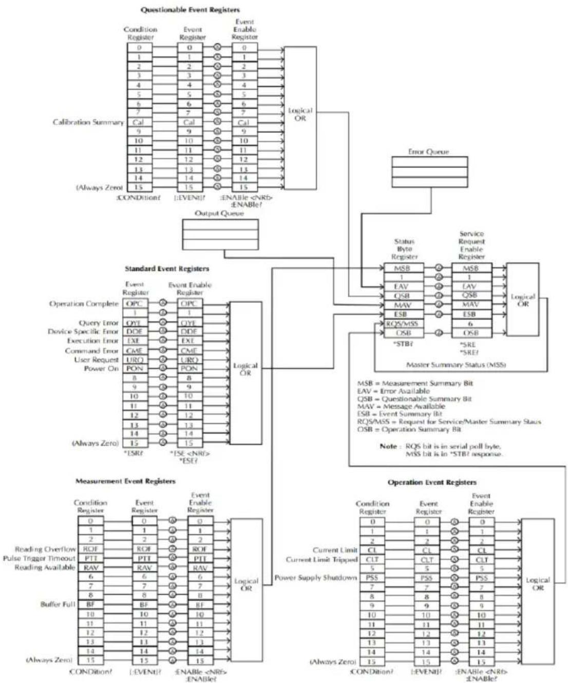
flowchart
graph TD
    subgraph Questionable Event Registers
        A["Calibration Summary"] --> B["Condition Register"]
        A --> C["Event Register"]
        A --> D["Event Enable Register"]
        A --> E["Logical OR"]
        F["(Always Zero)"] --> G["±CONDITION?"]
        F --> H["±EVENT?"]
        F --> I["±ENABLE <NRB> ±ENABLE?"]
    end

    subgraph Standard Event Registers
        J["Operation Complete"] --> K["OPC"]
        J --> L["OYT"]
        J --> M["DDE"]
        J --> N["EXE"]
        J --> O["CME"]
        J --> P["URO"]
        J --> Q["PON"]
        J --> R["8"]
        J --> S["9"]
        J --> T["10"]
        J --> U["11"]
        J --> V["12"]
        J --> W["13"]
        J --> X["14"]
        J --> Y["15"]
        J --> Z["*ESR?"]
        J --> AA["*ISE <NRB> *ESE?"]
    end

    subgraph Measurement Event Registers
        AB["Measurement Event Register"] --> AC["Condition Register"]
        AB --> AD["Event Register"]
        AB --> AE["Event Enable Register"]
        AB --> AF["Logical OR"]
    end

    subgraph Operation Event Registers
        AG["Current Limit Current Limit Tripped"] --> AH["Power Supply Shutdown"]
        AI["(Always Zero)"] --> AJ["±CONDITION?"]
        AI --> AK["±EVENT?"]
        AI --> AL["±ENABLE <NRB> ±ENABLE?"]
    end

    B --> G
    C --> K
    D --> M
    E --> N
    F --> R
    K --> S
    L --> T
    M --> U
    N --> V
    O --> Y
    R --> Z
    AA --> AH
    AF --> AI
    AH --> AG
    AI --> AG
    style Questionable Event Registers fill:#f9f,stroke:#333
    style Standard Event Registers fill:#ccf,stroke:#333
    style Operation Event Registers fill:#cfc,stroke:#333
*Note: URQ indicates that the "Lock" key on the panel has been used. (Entering lock from unlock or Entering unlock from lock).
Event Registers
The operation, measurement and questionable status register groups all have event registers. The event registers are read only registers that reflect the status of the unit. Individual bits in the event registers are latched (set) when a corresponding event occurs and will remain latched even if the corresponding event changes, as long as the event bit is still set. The register query (*ESR) or the command (*CLS) will automatically clear any set bits in the event registers. The reset command (*RST) will not clear the bits in the event register. Queries for the event registers will return a binary-weighted decimal value that represents the state of all the bits in an event register.
Enable Registers
The enable registers define which bits in the corresponding event register can be latched (set). The enable register can be read and written to. Any queries for the enable register will not clear the value in the register. The *CLS command will not clear the enable register, but will clear the events in the event register. To allow the individual bits in the event registers to be set, the corresponding bits in the enable registers must be set, where each bit is represented by a binary number.
The status byte register reports the status of the other status registers. The message available bit (bit 4), will indicate when there is a message in the output buffer. Clearing an event register will clear the corresponding bit in the status byte condition register. Reading all the data in the output buffer will clear the message available bit. To set the enable register mask for the status byte register and to generate an SRQ (service request) you must use the *SRE command to write the appropriate decimal value to the register.
Bit Definition for the Status Byte Register
| Bit number | Decimal value | Definition |
| 0 Not used | 1 | Not used, returns “0” |
| 1 Not used | 2 | Not used, returns “0” |
| 2 Error Queue | 4 | Indicates that one or more errors are stored in the error queue. |
| 3 Questionable Summary bit | 8 | One or more bits are set in the questionable data register (for enabled events). |
| 4 Message Available bit | 16 | Indicates that a message is available in the output queue. |
| 5 Standard Event Summary bit. | 32 | Indicates that one or more bits are set in the standard event register. (For enabled events). |
| 6 Master Summary bit | 64 | Indicates that a summary bit is set in the status byte register. (for enabled summary bits) |
| 7 Unused | 128 | Not used, returns “0” |
The status byte condition register is cleared when one of the following occurs:
- *CLS command is used to clear the status byte register.
- You read the event register from another register group (only clear the corresponding bit in the condition register)
The status byte enable register is cleared when the following occurs:
- When the *SRE 0 is command is executed.
Use the *STB? query to read the status byte register.
The *STB? query will return the contents of the status byte register as long as the bit 6 (MSS) has been cleared.
Using the *OPC? query to place a signal in the output buffer.
In general it is best to use the Operation Complete Bit (bit 0) in the standard event register to check to see if an operation/command has
completed. After executing the *OPC command, the OPC bit will be set to 1. If a command or query is placed in the output buffer immediately before the *OPC command is sent, the Operation Complete Bit can be used to determine when the information can be used. However if too many commands/queries are executed prior to the execution of the *OPC command, the output buffer could become saturated and the unit will stop taking readings.
Standard Event Register
The Standard Event Register reports the following types or events: Power on has been detected, command syntax errors, command execution errors, self test and execution errors, query errors or if the *OPC command is executed. Any one or more of these events will set the standard event summary bit in the status byte register. To set a mask for the enable register, a binary-weighted decimal number must be written using the *ESE command.
Bit Definition for the Standard Event Register
| Bit number | Decimal value | Definition |
| 0 Operation Complete Bit | 1 | The *OPC command will set this bit when all overlapping operations have completed (including the *OPC command itself). |
| 1 Not used | 2 | Not used, returns 0. |
| 2 Query Error | 4 | The instrument tried to read the error queue when the queue was empty or the queue was read before a new command was given or the input/output buffers are full. |
| 3 Device Error | 8 | A self-test, calibration or other device-specific error. |
| 4 Execution Error | 16 | An execution error. |
| 5 Command Error | 32 | A command syntax error. |
| 6 Not used | 64 | Not used, return 0. |
| 7 Power On | 128 | This bit is set if the power supply has been reset from the last time you read the event register. |
The following will clear the standard event register:
•The *CLS command is executed.
•The *ESR? command is used to query the event register.
The following will clear the standard event enable register.
•The *ESE command is executed.
Status Byte Register Commands
| Command | *SRE |
| Function | Service request enable register (SRER) command that writes a binary weighed value which determines which events in the status byte register are enabled. |
| Function | Allowed Decimal vales: 0~255 values |
| Example | *SRE 7Returns the SRER setting (0000 0111) |
| Command | *SRE? |
| Function | Queries the status byte enable register. This command returns a binary-weighted decimal number that indicates which bits are set in the status byte register. The range is from 0~255. |
| Example | *SRE?Returns “7”, which are the contents of the service request enable register. |
| Function | *STB? |
| Function | Query the status byte register. This is the same as performing a serial poll, however the master summary bit (MSS, bit 6) will not be cleared by the *STB command. The return value range is from 0 to 255. |
| Example | *STB?Returns 81 if the status byte register is set to 0101 0001. |
Standard Event Register Commands
| Command | *ESE |
| Function | Sets the standard event enable register. The allowable value range is 0~255. |
| Example | *ESE 65Sets the ESER as 0100 0001. |
| Command | *ESE? |
| Function | Queries the standard event enable register. It returns are binary-weighted decimal value representing all the enabled bits in the standard event register. |
| Example | *ESE?Returns 65, as the ESER is set as 0100 0001. |
| Command | *ESR? |
| Function | Queries the standard event register. It returns a binary-weighted decimal value in the range of 0~255. |
| Example | *ESR?It returns 198, as the ESER is set as 0100 0001. |
Other Status Register Commands
| Command | *CLS |
| Function | Clears the status byte summary registers and the all event registers. |
| Example | *CLSClears all the event registers. 涵盖 Standard event registers, Operation event registers, Measurement event registers, Questionable event registers. |
| Command | *OPC |
| Function | After all the pending operations are complete, sets the operation complete bit in the standard event status register. |
| Example | *OPC |
| Command | *OPC? |
| Function | Will return “1” to the output queue when all pending operations have been completed. |
| Example | *OPC?After the last command is executed, will return a “1” to the output queue. |
Errors
Error Message
- Errors are stored in a first in-first out (FIFO) order. The first error message that is returned is the first error message that was stored. When an error is read it is also cleared from the queue.
- If there are more than 10 errors produced the last error in the queue is replaced with “Que overflow”. Unless the error queue is cleared, no more errors can be written to the error queue. If there are no errors in the error queue, the instrument will return “No error”.
- To clear the error queue, you can use the :SYSTem:CLEar command or cycle the power. When you read a message from the error queue that message will be cleared from the error queue. Using the *RST command to reset the instrument does not clear the error queue.
- Remote control instructions can be used to clear the error queue. See the instructions listed in the previous chapter for details.
Command Errors
-440 Query unterminated after indefinite
-430 Response
-420 Query deadlocked
-410 Query unterminated
-363 Query interrupted
-350 Input buffer overrun
-330 Queue overflow
-314 Self-test failed
-315 Save/recall memory lost
-260 Configuration memory lost
-241 Expression error
-230 Hardware missing
-225 Data corrupt or stale
-224 Out of memory
-223 Illegal parameter value
-222 Too much data
-221 Parameter data out of range
-220 Settings conflict
-200 Parameter error
-178 Execution error
-171 Expression data not allowed
-170 Invalid expression
-161 Expression error
-160 Invalid block data
-158 Block data error
-154 String data not allowed
-151 String too long
-150 Invalid string data String data error
-148 Character data not allowed
-144 Character data too long
-141 Invalid character data
-140 Character data error
-124 Too many digits
-123 Exponent too large
-121 Invalid character in number
-120 Numeric data error
-114 Header suffix out of range
-113 Undefined header
-112 Program mnemonic too long
-111 Header separator error
-110 Command header error
-109 Missing parameter
-108 Parameter not allowed
-105 GET not allowed
-104 Data type error
-103 Invalid separator
-102 Syntax error
-101 Invalid character
-100 Command error
+000 No error
+101 Operation complete
+301 Reading overflow
+302 Pulse trigger detection timeout
+306 Reading available
+310 Buffer full
+320 Current limit event
+321 Current limit tripped event
+409 OTP Error
+410 OVP Error
+438 Date of calibration not set
+440 Gain-aperture correction error
+500 Calibration data invalid
+510 Reading buffer data lost
+511 GPIB address lost
+512 Power-on state lost
+514 DC Calibration data lost
+515 Calibration dates lost
+522 GPIB communication data lost
+610 Questionable calibration
+900 Internal system error
APPENDIX
Replacing the Fuse
Steps
Remove the power cord and then take out the box using a small screw driver.
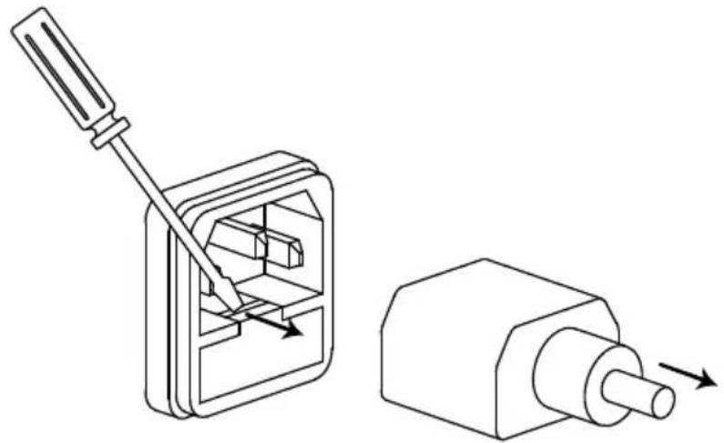
natural_image
Technical line drawing of a mechanical switch device with two views: one showing internal components and the other showing a cylindrical component (no text or symbols)The fuse is stored in the housing.
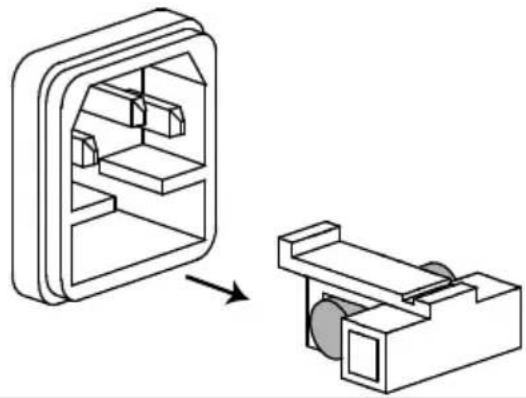
natural_image
Diagram showing a 3D mechanical assembly transforming into a simplified version of a housing (no text or symbols present)Rating
• T2.0A/250V (PPH-1503D)
• T2.5A/250V (PPH-1506D/1510D)
Battery Replacement
Step
- Remove the handle.

text_image
40000000 40000000 300-200-200-200- Remove the six screws on both sides and the four screws on the rear.

text_image
Technical diagram of an electronic device with labeled ports and connectors- Open the cover. Find the location indicated by the arrow in the figure shown below and then replace the battery with a new one.
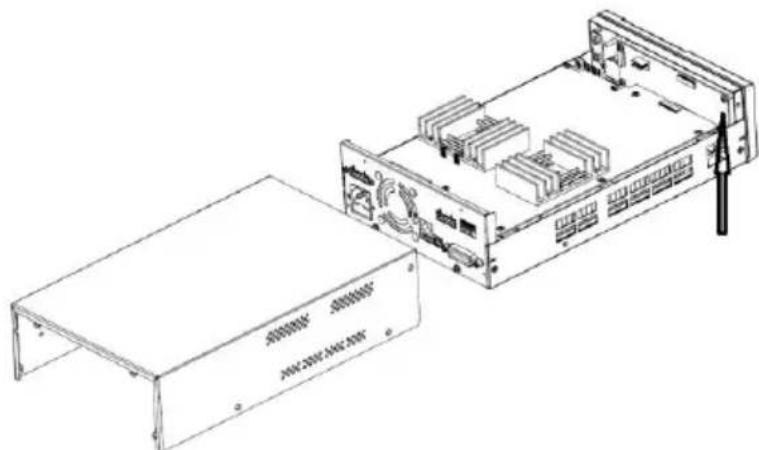
natural_image
Technical line drawing of an electronic device chassis with a flat base and internal components (no text or symbols visible)Specifications
The specifications apply under the following conditions: The PPH-1503D/1506D/1510D is powered on for at least 30 minutes, within +18°C→+28°C.
| DC GENERAL | MEASUREMENT TIME CHOICES | 0.01~10PLC ^1 ,0.01PLC/step |
| AVERAGE READINGS | 1~10 | |
| TYPICAL READING TIME ^2,3 | 31ms | |
| DC VOLTAGE OUTPUT (23°C±5°C) | OUTPUT VOLTAGE | CH1.0~15V CH2.0~12V |
| OUTPUT ACCURACY | ±(0.05%+10mV) | |
| PROGRAMMING | 2.5mV | |
| RESOLUTION | ||
| READBACK ACCURACY ^4 | ±(0.05%+3mV) | |
| READBACK RESOLUTION | 1mV | |
| OUTPUT VOLTAGE RISING TIME | 0.20ms (10%~90% On) | |
| OUTPUT VOLTAGE FALLING TIME | 0.30ms (90%~10% Off) | |
| LOAD REGULATION | 0.01%+2mV | |
| LINE REGULATION | 0.5mV | |
| STABILITY ^4 | 0.01%+3mV | |
| RECOVERY TIME(1000%LOAD CHANGE) | <40us (<100mV, Rear)<50us (<100mV, Front)<80us (<20mV) | |
| RIPPLE AND NOISE^5 | 3mV rms(0~1MHz)8mVpp(20Hz~20MHz) (SSA)12mVrms(20Hz~20MHz, OffSA) |
| READBACK RESOLUTION | 1.5A/3.0A &5A range: 100uA500mA range: 10uA5mA range: 0.1uA | |
| CURRENT SINK CAPACITY | CH1:0~4V: 3.5A4~15V: 3.5A-(0.25A/V)*(Vset-4V)CH2: 0~5V: 2A(PPH-1503D)3A(PPH-1506D/1510D)5~12V:2.0A-(0.1A/V)*(Vset-5V) (PPH-1503D)3.0A-(0.25A/V)*(Vset-5V) (PPH-1506D/1510D) | |
| LOAD REGULATION | 0.01%+1mA | |
| LINE REGULATION | 0.5mA | |
| DVM | INPUT VOLTAGE RANGE | 0 ~ 20VDC |
| INPUT IMPEDANCE | 20MΩ | |
| MAXIMUM INPUT VOLTAGE | -3V, +22V | |
| READING ACCURACY3 | ± (0.05%+3mV) | |
| READING RESOLUTION | 1mV | |
| PULSE CURRENT MEASUREMENT | TRIGGER LEVEL | CH1:5mA~5A,5mA/stepCH2:5mA~1.5A/3.0A,5mA/step |
| HIGH TIME/LOW | 33.3us to 833ms, 33.3us/step | |
| TIME/AVERAGE TIME | ||
| TRIGGER DELAY | 0 ~ 100ms,10us/steps | |
| AVERAGE READINGS | 1 ~ 100 | |
| LONG INTEGRATION PULSE TIMEOUT | 1S ~ 63S | |
| LONG INTEGRATION MEASUREMENT TIME | 850ms(60Hz)/840ms(50Hz) ~60s,or AUTO time16.7ms/steps(60Hz),20ms/steps(50Hz) | |
| LONG INTEGRATION TRIGGER MODE | Rising, Falling, Neither | |
| Resistance | RANGE | 0.001Ω~1.000Ω |
| PROGRAMMED RESOLUTION | 0.001Ω | |
| PROGRAMMED ACCURACY | ± (0.5%+0.01Ω) | |
| OVP | OVP RANGE | Auto, OFF, ON(CH1:1.00~15.2V;CH2:1.00~12.2V) |
| RESOLUTION | 10mV | |
| ACCURACY | CH:1 0.8V CH2: 50mV | |
| Others | PROGRAMMING | IEEE-488.2(SCPI) |
| USERDEFINABLE POWER_UP STATES | 5 sets | |
| REAR PANEL CONNECTOR | 5Pin*2:output*2,sense*2,Ground*1 | |
| TEMPERATURE COEFFICIENT | 0.1* specification/ °C | |
| POWER CONSUMPTION | 160W(PPH-1503D),180W(PPH-1506D), 210W(PPH-1510D) | |
| REMOTE/LOCATION CONNECTOR | USB/GPIB/LAN | |
| RELAY CONTROL CONNECTOR | 150mA/15V 5Voutput, 100mA | |
| Insulation | Chassis and Terminal Chassis and AC cord | 20MΩ or above (DC 500V)30MΩ or above (DC 500V) |
| Operation Environment | Indoor use, Altitude: ≤ 2000mAmbient temperature: 0 ~ 40°CRelative humidity: ≤ 80%Installation category: II,Pollution degree: 2 | |
| Storage Environment | TEMPERATURE: -20°C ~ 70°CHUMIDITY: < 80% | |
| INPUT POWER | 90-264VAC, 50/60Hz ^6 | |
| Accessories | CD User manual x1, Quick Start manual x1Test lead GTL-207A x 1GTL-203A x 1, GTL-204A x 1 | |
| Dimensions | 222 (W) x 86 (H) x 363 (D) mm | |
| Weight | Approx. 4.5kg | |
| Remarks | ^1 PLC=PowerLineCycle, 1PLC = 16.7ms for 60Hz operation, 20ms for 50Hz operation; ^2 Display OFF, Speed includes measurement and binary data transfer out of GPIB; ^3 PLC=1; ^4 STABILITY: Following 15 minute warm-up, the change in output over 8 hours under ambient temperature, constant load, and line operating conditions; ^5 The ground ring of the probe is pressed directly against the output ground of the power supply and the tip is in contact with the output voltage pin. ^6 Auto detected at power-up; |
Optional Accessories
USB Cable
GTL-246
USB 2.0, A-B type
Declaration of Conformity
We
GOOD WILL INSTRUMENT CO., LTD.
declare, that the below mentioned product
Type of Product: Programmable High Precision DC Power Supply Model Number: PPH-1503D/1506D/1510D
satisfies all the technical relations application to the product within the scope of council:
Directive: 2014/30/EU; 2014/35/EU; 2011/65/EU; 2012/19/EU
The above product is in conformity with the following standards or other normative documents:
© EMC
| EN 61326-1:EN 61326-2-1: | Electrical equipment for measurement, control and laboratory use -- EMC requirements (2013) | |
| Conducted & Radiated EmissionEN 55011: 2009 +A1: 2010 Class A | Electrical Fast TransientsEN 61000-4-4: 2012 | |
| Current HarmonicsEN 61000-3-2: 2014 | Surge ImmunityEN 61000-4-5: 2014 | |
| Voltage FluctuationsEN 61000-3-3: 2013 | Conducted SusceptibilityEN 61000-4-6: 2014 | |
| Electrostatic DischargeEN 61000-4-2: 2009 | Power Frequency Magnetic FieldEN 61000-4-8: 2010 | |
| Radiated ImmunityEN 61000-4-3:2006+A1:2008+A2:2010 | Voltage Dip/ InterruptionEN 61000-4-11: 2004 | |
© Safety
| Low Voltage Equipment Directive 2014/35/EU | |
| Safety Requirements | EN 61010-1: 2010 |
GOOD WILL INSTRUMENT CO., LTD.
No. 7-1, Jhongsing Road, Tucheng Dist., New Taipei City 236, Taiwan
Tel: +886-2-2268-0389 Fax: +866-2-2268-0639
Web: www.gwinstek.com Email: marketing@goodwill.com.tw
GOOD WILL INSTRUMENT (SUZHOU) CO., LTD.
No. 521, Zhujiang Road, Snd, Suzhou Jiangsu 215011, China
Tel: +86-512-6661-7177 Fax: +86-512-6661-7277
Web: www.instek.com.cn Email: marketing@instek.com.cn
GOOD WILL INSTRUMENT EURO B.V.
De Run 5427A, 5504DG Veldhoven, The Netherlands
Tel: +31(0)40-2557790 Fax: +31(0)40-2541194
Email: sales@gw-instek.eu