
AV4PRO-VGA - KVM Switch Adder - Free user manual and instructions
Find the device manual for free AV4PRO-VGA Adder in PDF.

| Product Type | 4-Port Professional KVM Switch |
| Brand | Adder |
| Model | AV4PRO-VGA |
| Video Support | VGA (single head); multiscreen versions support up to 4 heads per channel |
| Number of Computers | 4 |
| True Emulation | Yes, copies full keyboard/mouse identity to all connected computers |
| EDID Emulation | Yes, supplies correct display information to each computer |
| Switching Modes | KVM, SPK, USB1, USB2 individually or combined |
| User Console Ports | 2x USB (keyboard/mouse), 2x USB (enumerated), 1x VGA, 1x audio out (3.5mm) |
| Computer Channel Ports | 4x USB B-type, 4x VGA, 4x audio in (3.5mm) |
| Options Port | 10p10c (accepts 8p8c) for RC4 remote, RS-232, or upgrade |
| Power Supply | 12.5W (single head) or 20W (multiscreen) external adapter |
| Dimensions (approx) | Single head: 250 x 150 x 50 mm |
| Weight (approx) | Single head: 1 kg |
| Hotkeys | Ctrl+Alt (default, configurable) or mouse buttons |
| Autoscan | Yes, with adjustable delay (2 sec to 5 min) |
| Lock/Password Protection | Yes, password lock to prevent access |
| Firmware Upgrade | Via RS-232 (Windows utility) |
| Operating Temperature | 0°C to 40°C |
| Safety | Do not enclose or block ventilation; avoid ambient >40°C |
| Cleaning | Disconnect power; wipe with dry cloth; no liquids |
| Spare Parts / Repairability | Contact Adder Technology or authorized resellers |
| Standards | USB Remote Wakeup supported |
Frequently Asked Questions - AV4PRO-VGA Adder
User questions about AV4PRO-VGA Adder
0 question about this device. Answer the ones you know or ask your own.
Ask a new question about this device
Download the instructions for your KVM Switch in PDF format for free! Find your manual AV4PRO-VGA - Adder and take your electronic device back in hand. On this page are published all the documents necessary for the use of your device. AV4PRO-VGA by Adder.
USER MANUAL AV4PRO-VGA Adder
What is True Emulation? 3
AV4PRO-VGA features - front and rear 4
What's in the box 5
What you may additionally need....5
Installation
Mounting 6
Connections 7
User console 7
Computer systems....8
Power in connection....9
Optional RC4 remote control 9
Channel switching by external control 10
Synchronising multiple units....11
Managing EDID video display information....12
Configuration
Using the configuration menu 13
General configuration....14
Changing hotkeys....14
Mouse switching 14
OPTIONS port speed 14
OPTIONS port channel control behaviour....14
Switching mode 15
Miscellaneous functions ....15
Performing upgrades 16
Operation
Selecting a computer....18
To select a computer using the front panel....18
To select a computer using hotkeys 19
To select a computer using the mouse buttons....20
To lock access to the computers ....21
Autoscanning....22
Further information
Getting assistance....23
Appendix 1 – Default EDID video modes....24
Appendix 2 – Cable pin-outs....25
Index

Introduction
Thank you for choosing a member of the AdderView PRO (AV4PRO) family of professional switches from Adder Technology. There are four versions of the four-way AV4PRO-VGA, each of which allows a single operator to control up to four computer systems and share peripherals among them in a very flexible manner. The AV4PRO-VGA can support one video head per channel, whereas the slightly larger AV4PRO-VGA-DUAL, AV4PRO-VGA-TRIPLE and AV4PRO-VGA-QUAD units support two, three and four video heads per channel, respectively.
In addition to impressive VGA video performance, these units offer more than just straight switching between four systems. The KVM, speakers and two separate USB devices attached to the AV4PRO-VGA units can either be switched in unison, as normal, or you can mix your peripherals between any of the systems to suit your current tasks. For instance, you could be creating emails on one system, listening to a soundtrack from another while a third is sending documents to your printer and a fourth performing another task with a different
USB peripheral. The AV4PRO-VGA front panels make it straightforward to control which peripherals should connect to each system.
The AV4PRO-VGA units feature True Emulation which ensures that the full characteristics of the connected keyboard and mouse are passed to every system.
Multiscreen versions
The AV4PRO-VGA range includes separate models to support one, two, three or four video heads per channel.
Intelligent display information
The AV4PRO-VGA units use our EDID Emulation feature to ensure that all computers are supplied with the correct information about each connected video display.

flowchart
graph TD
    A["KVM"] --> B["Computer"]
    C["SPK"] --> D["Server"]
    E["1"] --> F["Printer"]
    G["2"] --> H["Printer"]
    B --> I["AOSERVIEW"]
    D --> I
    F --> I
    H --> I
    I --> J["Server 1"]
    I --> K["Server 2"]
    I --> L["Server 3"]
Multiple switching
The attached peripheral devices can be switched collectively to any computer system, or can be linked to separate systems to achieve multiple tasks in parallel. Multiple switching can be controlled from the on-screen menu or using the front panel buttons.
True Emulation
Earlier USB I/KVM switches relied upon standard keyboard and mouse templates to inform each computer system how to deal with the connected peripherals. The AV4PRO-VGA range succeeds in harvesting the true identities of the connected keyboard and mouse and presents those 'real' profiles concurrently to every system. Thus, specialist keyboards and mice can be fully supported.
USB Remote wakeup
The USB Remote Wakeup feature is fully supported. Any connected computer can go into sleep mode and be awakened (when its channel is selected) as soon as you press a key or move the mouse. The computer and peripherals must support the USB Remote Wakeup feature.

What is True Emulation?
True Emulation represents a significant breakthrough in sharing USB devices between two or more computer systems. Until this point, the problem has been how to create a USB switch that provides all of the following:
• Quick, transparent and reliable switching,
• Accurate representation of the connected USB keyboard and mouse,
• Switching control via the connected USB keyboard and/or mouse.
The difficulty in achieving all of the above requirements has been due to the complexity of the USB standard. This has led to various problems that have spawned a number of possible solutions.
Enumerated USB switching
The earliest attempts to switch USB devices applied a relatively 'hands off' approach. Enumerated USB switches are the electronic equivalent of those old mechanical KVM switches with a large knob on the front.
Enumerated switches are so called because a connected USB device will be required to perform a full initiation (a process called Enumeration) every time it is switched; just as if you had pulled out the plug and then reconnected it.
Enumerated switches simply pass all signals straight through between the USB device and the computer, they do not attempt to interpret any data. For most devices, this offers an advantage because the switch just leaves them to get on with their jobs without any interference or any hit on performance. However, it means that a USB keyboard or mouse cannot be used to control the switching process - a quick and simple control method expected by most users. Reliability of switching is also an issue that has plagued enumerated switches, especially when used with certain USB devices and particular operating systems.
Emulated USB switching
The issues with interpreting the complex USB data streams and recreating (or Emulating) the identity of attached USB devices were eventually solved, leading to the creation of the Emulated USB switch.
A neat side effect of the technique used is that each computer can be fooled into thinking that the USB device is permanently connected to it, even when the device is switched to another computer. This means that the enumeration process for the USB device takes place only once, during the first power on. After that, a computer merely sees a dormant version of the USB device whenever the device is actually connected to a different computer.
However, it remains a complex task to dynamically assume the identity of a USB device, distribute it among the connected computers and maintain all of the necessary signals, states and processes. Therefore, manufacturers have previously relied upon a fixed keyboard and mouse profile that is declared to each computer, regardless of the actual connected devices. This precluded the use of any special keyboard or mouse features over and above the standard layouts.
True Emulation
Mindful of the limitations associated with the previous USB switching techniques, we set about creating a more effective and elegant solution. After a great deal of research and development, True Emulation is the result.
True Emulation allows the complete identity of the keyboard and mouse to be copied and then presented to all of the connected computers. This means that any keyboard offering specialist function keys or any mouse with extra features will be fully supported at each computer. As with the previous emulation method, the unselected computers will continue to see the identities of the keyboard and mouse, which means that no enumeration is necessary when their link becomes active once again. This not only helps to speed up the rate of reconnection, but also raises the reliability of switching because USB links are at their most vulnerable during the enumeration process.
True Emulation relies upon a high speed circuit, called an Emulation Engine, to fully emulate the USB device identities and also interpret keyboard and mouse data streams. The result is full support for KVM switching control via hotkey presses or the third button/scroll wheel of a mouse.
True Emulation is not necessarily required by other USB devices, which is why you will also find two enumerated circuits included (shown in green within the block diagram) alongside the True Emulation feature (shown in blue). This allows those other USB devices to operate at their highest speeds, without any intervention. The enumerated circuits benefit greatly from the USB Hubs that are jointly used with the True Emulation system. Because they interface directly and permanently with each computer, they help to stabilise the dormant links, making errors during enumeration much less likely.
The dual switching arrangement provides further flexibility because the True Emulation and enumerated sections can be switched in unison or independently of each other, as required. Thus, your various peripherals can operate with different computers at the same time.


flowchart
graph TD
    A["USB KEYBOARD"] --> B["HOST CONTROLLER"]
    C["USB MOUSE"] --> B
    D["OTHER USB DEVICE"] --> B
    B --> E["EMULATION ENGINE"]
    E --> F["PC 1"]
    E --> G["PC 2"]
    E --> H["PC 3"]
    E --> I["PC 4"]
    J["USB HUB"] --> K["+"]
    L["USB HUB"] --> K
    M["USB HUB"] --> K
    N["USB HUB"] --> K
    K --> O["PC 1"]
    K --> P["PC 2"]
    K --> Q["PC 3"]
    K --> R["PC 4"]
The emulated section of the switch is shown in blue and handles only the keyboard and mouse. The green enumerated section of the switch handles other USB devices and also uses the USB hubs to link with the computers.
AV4PRO-VGA features - front and rear
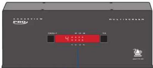
The AV4PRO-VGA single screen and multiscreen units are housed within durable, metallic enclosures with all connectors situated at the rear panel. The smart front face features the control buttons and the operation indicators.

COMPUTER button
Press to change to the next computer channel.
Indicators
The four indicators (KVM, SPK, USB1, USB2) show which peripherals are switched to the current computer channel OR (as you begin pressing the MODE button) the peripherals that will be switched during the next press(es) of the COMPUTER button.
The seven segment numeric display indicates the computer channel that is currently active.
MODE button
Press to determine which peripherals should be switched to another computer channel (will occur when the COMPUTER button is pressed.
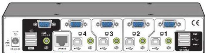
Power input The power supply connects here.
User console Connect VGA video, USB keyboard and mouse plus optional speakers to these connectors.
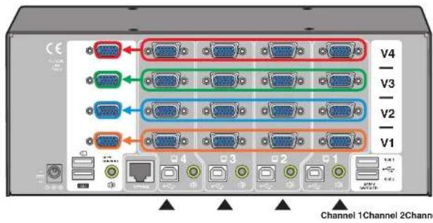
Computer channels
Each computer connects to one of these four channels via a VGA video connector, a USB B-type connector and an audio 3.5mm jack input.
User console
Connect up to two USB devices to these connectors. These ports are switched in an enumerated manner (see What is True Emulation?)
Options port
This 10p10c port can separately support the following functions:
- Remote control - external switching control via Adder RC4 remote unit, RS-232 serial link or channel switching input lines (see Optional RC4 remote control or Channel switching by external control for details).
- Upgrades - used to update the internal firmware when necessary by connecting to a computer.
Multiscreen versions
The Dual, Triple and Quad video screen versions use a larger casing and provide more connectors on the rear panel.
Extra indicators
As well as the indicators shown on the single screen version, the multiscreen units also include four indicators, labelled V1 to V4, which show the video channels being switched.

natural_image
Front view of a network switch device with multiple ports (V1–V4) and indicator lights, no visible text or symbols on the device body.Extra video channels
In addition to all of the ports described (left) for the single screen version, the multiscreen versions provide additional VGA connectors to allow multiple video streams from each computer to be switched to (up to) four video monitors.

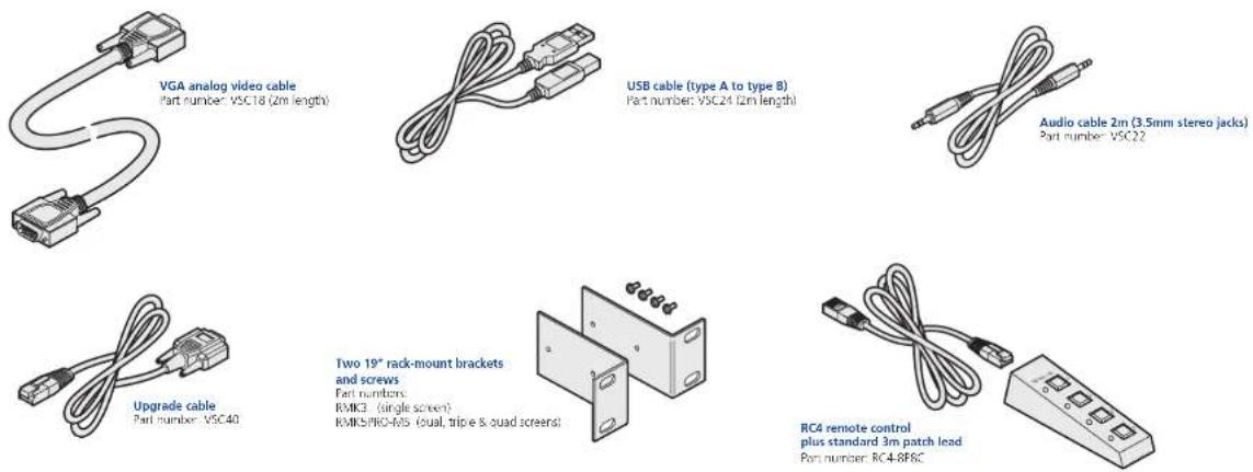
What's in the box


What you may additionally need
Installation
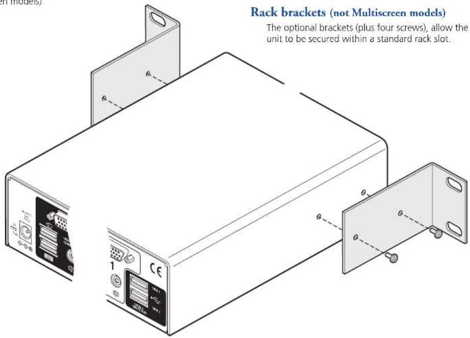
Mounting
There are two main mounting methods:
• The supplied four self-adhesive rubber feet
• Optional rack brackets (not Multiscreen models)
Connections
Note: Both the AV4PRO-VGA unit and its power supply generate heat when in operation and will become warm to the touch. Do not enclose them or place them in locations where air cannot circulate to cool the equipment. Do not operate the equipment in ambient temperatures exceeding 40 degrees Centigrade. Do not place the products in contact with equipment whose surface temperature exceeds 40 degrees Centigrade.

Connections
Connections do not need to be carried out in the order given within this guide, however, where possible connect the power in as a final step.
User console
The ports that make up the user console are where you attach the peripherals that will be shared between the computer systems. Ensure that power is disconnected from the unit.
To connect peripherals to the user console
1 Position your peripheral devices in the vicinity of the unit such that their cables will easily reach.
2 Keyboard and mouse: Attach the leads from your USB keyboard and mouse to the USB sockets specifically labelled with keyboard and mouse symbols. The keyboard and mouse will operate in any of the USB sockets, however, True Emulation is not available on sockets labelled USB1 or USB2.
Note: The unit's True Emulation feature will read the full characteristics of the keyboard and mouse and will present those to each connected computer concurrently. This ensures that specialist keyboards and mice are fully supported.

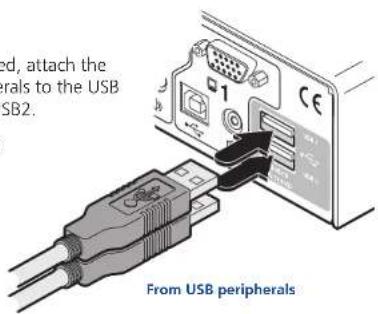
3 USB devices: Where required, attach the leads from your USB peripherals to the USB sockets labelled USB1 and USB2.
Note: These sockets provide enumerated (transparent) switching.
4 Video monitor(s): VGA video ports are used throughout.
Single screen units: Attach the lead from the video monitor to the VGA connector of the user console area.
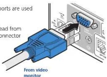
During initial power up, the AV4PRO-VGA unit will attempt to read the EDID information from the connected display(s). See Managing EDID video display information for details.
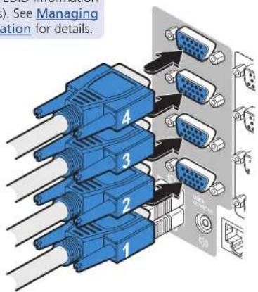
Multiscreen units: Attach the lead from each video monitor to a VGA connector of the user console area. Note: On the rear panel of the unit, the connectors at each horizontal level (V1 to V4) will be switched through to the user console VGA connector which is at the same level.
From video monitors
5 Audio: Where required, connect the lead from your speakers to the audio socket.


Computer systems
Each computer system is connected to the AV4PRO-VGA unit using up to three cables.
To connect a computer system
1 Ensure that power is disconnected from the AV4PRO-VGA unit and the system to be connected.
2 Use a USB cable (type-A to type-B) to link a USB port on the computer system to the USB port of the required channel on the rear of the unit.
3 If required, use a stereo audio link cable (3.5mm jacks at either end) to link the speaker port on the computer system to the audio port of the required channel on the rear of the unit.
From the USB port on the computer

From the speaker port on the computer
4 Single screen units: Link the video output of the computer's graphic port to the VGA port of the required channel on the rear of the unit.
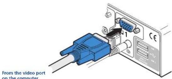
During initial power up, the AV4PRO-VGA unit will attempt to read the EDID information from the connected display(s). See Managing EDID video display information for details.
Multiscreen units: Link the video outputs of each computer to the VGA ports on the rear of the unit (see note below).
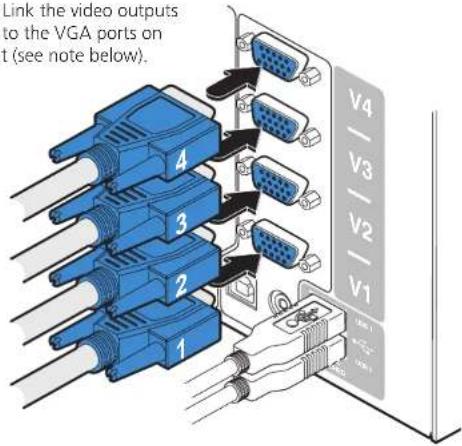
Note: On the rear panel of the unit, connectors belonging to the same channel are stacked vertically. The connectors at each horizontal level (V1 to V4) will be switched through to the user console VGA connector which is at the same level:

Power in connection
The AV4PRO-VGA unit is supplied with either a 12.5W (single screen version) or 20W (Multiscreen versions) power adapter. There is no on/off switch on the unit, so operation begins as soon as a power adapter is connected.
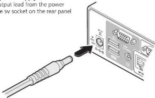
To connect the power supply
1 Attach the output lead from the power adapter to the sv socket on the rear panel of the unit.
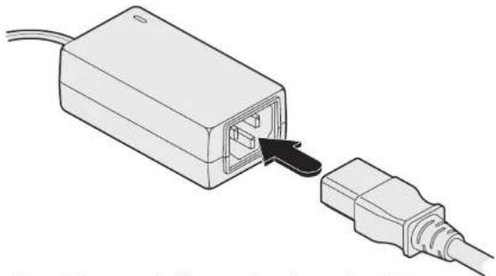
2 Connect the IEC connector of the supplied country-specific power lead to the socket of the power adapter.
natural_image
Diagram of a device with an attached cable showing internal components (no text or symbols)3 Connect the power lead to a nearby main supply socket.
Note: Both the unit and its power supply generate heat when in operation and will become warm to the touch. Do not enclose them or place them in locations where air cannot circulate to cool the equipment. Do not operate the equipment in ambient temperatures exceeding 40 degrees Centigrade. Do not place the products in contact with equipment whose surface temperature exceeds 40 degrees Centigrade.
Optional RC4 remote control
The optional RC4 remote control unit (full part number: RC4-8P8C) can be used to provide direct push button access to any channel from your desktop. The RC4 remote control is supplied with a 3 metre cable that is used to link with the OPTIONS port on the rear panel of the unit.
To connect the remote control
1 Connect either end of the supplied cable to the socket at the rear of the RC4 remote control.

natural_image
Diagram of a device with a cable and red indicator lights, showing no text or symbols2 Connect the other end of the cable to the OPTIONS port on the rear panel of the unit.

natural_image
Illustration of a USB cable inserted into an electronic device with ports and connectors (no text or symbols visible)
Channel switching by external control
The OPTIONS port featured on every AV4PRO-VGA allows external control of the current channel either by the optional RC4 controller, commands sent via RS-232 serial input or by switching one of the four channel select input lines. For more details about the necessary RS-232 serial cable, see Appendix 2.
OPTIONS port pinout
The OPTIONS port can accept either 8p8c or 10p10c connectors, as required.
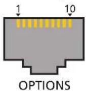
8p8c 10p10c Signal
| 1 | Channel select input 1 | |
| 1 | 2 | 5VDC power output (100mA max) |
| 2 | 3 | GND reference for all signals |
| 3 | 4 | RS232 (RXD) data receive |
| 4 | 5 | RS232 auxiliary data transmit (reserved) |
| 5 | 6 | RS232 auxiliary data receive (reserved) |
| 6 | 7 | RS232 (TXD) data transmit |
| 7 | 8 | Channel select input 2 |
| 8 | 9 | Channel select input 3 |
| 10 | Channel select input 4 |
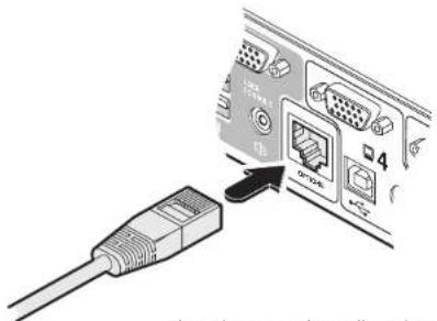
To connect a computer or device for remote control
1 Insert the 8p8c or 10p10c connector of the cable to the OPTIONS port on the rear panel of the unit.

natural_image
Diagram showing a cable connector inserted into an ABCD card with port labels (no text or symbols on the diagram itself)2 Connect the other end of the cable to a vacant serial port on the computer or to the output of the switching device.
Control by RS-232 serial
Where the external control is via RS-232 signal, ensure that the configuration menu option ☑ set to ☐ to ☑able RS-232 control.
Serial port parameter settings
Ensure that the chosen serial port is configured to the following:
- Baud rate: To match setting of B option in the Configuration menu
- Data bits: 8
- Stop bit: 1
- Parity: None
Serial port channel selection codes
ASCII
| Character | Hex | Decimal | |
| Channel 1: | '1' | 0x31 | 49 |
| Channel 2: | '2' | 0x32 | 50 |
| Channel 3: | '3' | 0x33 | 51 |
| Channel 4: | '4' | 0x34 | 52 |
Note: As each channel is chosen using the above RS-232 commands, the peripherals that will be transferred are determined by the current setting of the switching mode.
Control by channel select input lines
Where the external control is via the four channel select input lines of the OPTIONS port (see pin out opposite), ensure that the configuration menu option 0 is set to 3b enable the input lines.
The four input lines are suitable for connection to dry contacts or open collector style outputs. Connecting an input line to GND will cause the AV4PRO-VGA to switch all of its functions to the selected channel:
• Channel 1: Channel select input 1 low
• Channel 2: Channel select input 2 low
• Channel 3: Channel select input 3 low
• Channel 4: Channel select input 4 low
If the input line is held low then all other switching requests by other means will be ignored until the line returns to a high (open) state.
If more than one logic input is low (closed) then the lower channel number takes priority.
Note: The input lines have only limited protection against over voltage.

Synchronising multiple units
AV4PRO-VGA units can be connected together so that they operate in a synchronised manner. Thus, two AV4PRO-VGA units can be made to switch two video heads in a similar manner to an AVPRO-VGA-DUAL. Additionally, two AVPRO-VGA-DUAL units could be made to resemble an AVPRO-VGA-QUAD, while two AVPRO-VGA-QUAD units could be combined in order to switch up to eight video heads simultaneously.
Whenever an AV4PRO-VGA channel is switched, it sends an RS232 command out on its serial interface (marked OPTIONS on the rear panel). An AV4PRO-VGA will switch its channel if it receives the same command on its serial interface. Consequently, by linking the serial interfaces, a master unit may be made to automatically switch one or more slave units as shown in the diagram.
It should be noted that the synchronisation cable deliberately does not have the transmit pin of the Slave End connector linked to the receive pin of the Master End connector. To do so would cause the Slave unit to be able to switch the Master unit. This would setup an endless cyclical switching sequence that would prevent the AV4PRO-VGA devices from operating correctly. For more details about the serial synchronisation cables, see Appendix 2.

flowchart
graph TD
    A["Slave monitor"] --> B["Computer"]
    C["Master monitor"] --> B
    D["Computer"] --> E["Computer with multiple video heads"]
    F["Computer"] --> G["Computer with multiple video heads"]

Managing EDID video display information
Whenever a AV4PRO-VGA unit is powered on (or when the option [F2] selected from the configuration menu), it will interrogate the connected monitor(s) to determine whether EDID (Extended Display Identification Data) information is available. If EDID information is available, it will be copied and used; otherwise a default set of data, stored within the AV4PRO-VGA, will be substituted. You can also optionally choose to prevent the unit from seeking new EDID information and instead rely only on stored data.
EDID Emulation
The AV4PRO-VGA units use our EDID Emulation feature to ensure that the collected EDID information (up to two pages) is correctly supplied to every connected computer, whether it is currently selected or not:

Refreshing EDID information during use
You can refresh the EDID information from the connected monitor(s) without the need to power cycle the AV4PRO-VGA.
To refresh EDID information during use
1 Enter the Configuration menu.
2 Press F to enter the Functions menu
3 Press 2 and then Enter
4 Press E and then Enterxit the menu.
Using stored EDID information only
You can choose to prevent the unit from interrogating the video display(s) during startup. When you invoke this option, the unit will only use the EDID information that it has already stored and pass this on to the connected computers. To revert to interrogating the video display, use the F2 function discussed above.
To use the stored EDID information at the power up
1 Enter the Configuration menu.
2 Press F to enter the Functions menu
3 Press 3 and then Enter
4 Press End then t5next the menu.

Configuration
Using the configuration menu
The configuration mode allows you to determine numerous aspects of the AV4PRO-VGA unit capabilities.
To use the configuration menu
During normal use, the seven segment display on the front panel shows the number of the currently selected computer channel. From this condition, enter configuration mode as follows:
1 Press and hold the front panel COMPUTER button for roughly five seconds. The display will show: [
2 On the keyboard, press the letter key for the required menu section, e.g. S The display will show the pressed letter, e.g. 5
3 Press the number of the required setting, e.g. 4 The display will show the pressed number, e.g. 4
4 Press Enter accept the setting and return to the main menu section. The display will show: [
5 You can now continue with your next configuration change (go to step 2), or exit from the configuration menu (see below).
To exit the configuration menu and save changes
- Press and then press Enter exit and save changes.
To exit the configuration menu without saving
- Press either of the front panel buttons.
| B | Enter the OPTIONS port Baud rate menu | ||
| 1 1200 (default) | 38400 | 5 | |
| 2 2400 | 57600 | 6 | |
| 3 9600 | 115200 | 7 | |
| 4 19200 | |||
| F | Enter the Functions menu | ||
| 1 Show current firmware version | |||
| 2 Refresh EDID information from the connected video display (default) | |||
| 3 Use the stored EDID at startup, do not interrogate the video display | |||
| 8 Reset configuration to factory defaults (is displayed momentarily) | |||
| H | Enter the Hotkey menu | ||
| 1 Ctrl + Alt (default) | Alt | 5 | |
| 2 Ctrl + Shift | 6 Left Ctrl + Alt | ||
| 3 Alt + Shift | 7 Right Ctrl + Alt | ||
| 4 Right Alt | 8 Hotkeys disabled | ||
| O | Enter the Options port behaviour menu | ||
| 1 Channel switching via RS-232 serial control (using the baud rate set by the 'B' option). Contact switching via the Options port disabled. (3) | |||
| 2 Channel switching via RC4 remote. Contact switching disabled. | |||
| 3 As per (but with contact switching enabled. | |||
| P | Set a new password for use with the lock mode | ||
| S | Enter the Switch Mode menu | ||
| 1 All (default) | |||
| 2 KVM + Speaker | (default) or (2) denote the default settings for each group of options. | ||
| 3 KVM only | |||
| 4 Speaker only | |||
| 5 USB1 only | |||
| 6 USB2 only | |||
| T | Enter the Autoscan Time Delay menu | ||
| 1 Autoscan disabled | 5 15 seconds | ||
| 2 2 seconds | 6 30 seconds | ||
| 3 5 seconds (default) | 7 1 minute | ||
| 4 7 seconds | 8 5 minutes | ||
| U | Enter the User Preferences menu | ||
| 1 Enable mouse switching (default) | |||
| 2 Disable mouse switching | |||
| 7 Cycle all ports (when using 'Hotkey + Tab' or 'Autoscan') (default) | |||
| 8 Cycle only active ports (when using 'Hotkey + Tab' or 'Autoscan') | |||

General configuration
Changing hotkeys
AV4PRO-VGA units use Card as their standard hotkeys. These can be changed if they clash with other software or hardware within the installation.
To change the hotkeys
1 Enter the Configuration menu.
2 Press H to enter the Hotkey menu and then press either:
① to choose Ctrl + Alt
5 to choose Alt
2 to choose Ctrl + Shift
6 to choose Left Ctrl + Alt
3 to choose Alt + Shift
7 to choose Right Ctrl + Alt
4 to choose Right Alt
8 to disable the Hotkeys
3 Press Entercept the setting and return to the main menu section.
4 Press E and then Enter the menu and save changes.
Mouse switching
You can enable or disable mouse switching to suit your installation requirements.
To enable/disable mouse switching
1 Enter the Configuration menu.
2 Press U to enter the User Preferences menu and then press either:
to Enable mouse switching
② to Disable mouse switching
3 Press Enter accept the setting and return to the main menu section.
4 Press E and then Enterit the menu and save changes.
OPTIONS port speed
You can change the speed of the OPTIONS serial port.
To change the OPTIONS port speed
1 Enter the Configuration menu.
2. Press B to enter the Baud rate menu and then press either:
to choose 1200
5 to choose 38400
2 to choose 2400
6 to choose 57600
3 to choose 9600
7 to choose 115200
4 to choose 19200
3 Press Entercept the setting and return to the main menu section.
4 Press E and then Enter the menu and save changes.
OPTIONS port channel control behaviour
You can determine how the OPTIONS port responds to channel control inputs.
To define the OPTIONS port behaviour
1 Enter the Configuration menu.
2 Press 0 to enter the Options port menu and then press either:
10 allow channel switching commands to be received via RS-232 serial signal through the OPTIONS port (see Appendix 2 for cable pin-out details and Channel switching by external control for command details). The baud rate currently set by the [B]option will be used for the port. Switching commands via the four channel select inputs within the OPTIONS port connector are disabled in this mode. Use option [J] you wish to enable the channel select inputs in addition to RS-232 control.
② to allow channel switching commands to be received from the optional RC4 remote control (see Optional RC4 control for connection details). The baud rate set by the Boption is ignored and the rate used by the RC4 is automatically imposed. Switching commands via the four channel select inputs within the OPTIONS port connector are disabled in this mode.
3 enables channel switching via RS-232 as per option 1 However, in this mode the four channel select inputs are also enabled.
3 Press Entercept the setting and return to the main menu section.
4 Press E and then Enterit the menu and save changes.
continued

Switching mode
Using the configuration menu, you can define a default switching mode. The switching mode determines which peripherals (KVM, USB1, USB2 and/or speakers) should be moved to the next computer when it is selected using any of the standard methods. Regardless of the default switching mode set here, during use you can always change the mode using either the MODE button (on the front panel) or using the additional hotkey press combinations.
Note: Of the external switching methods, the RC4 remote and the RS-232 serial signal inputs will switch the peripherals as defined by the currently selected switching mode. However, switching control initiated by the channel select input lines will always switch all of the peripherals to the chosen channel regardless of the switching mode.
To set the default switching mode
1 Enter the Configuration menu.
2 Press S to enter the Switch Mode menu and then press either:
to select All (default)
2 to select KVM and speaker
to select KVM only
4 to select Speaker only
5 to select USB1 only
6 to select USB2 only
3 Press Enter accept the setting and return to the main menu section.
4 Press E and then enter the menu and save changes.
Miscellaneous functions
To refresh EDID information from the monitor
1 Enter the Configuration menu.
2 Press F to enter the Functions menu
3 Press 2 and then Enter
4 Press find then to enter the menu and save changes.
To use the stored EDID information at the power up
When you engage this mode, the unit will not interrogate the video display during startup and will instead use the data that are stored. To revert to interrogating the video display, use the F 2 function discussed above.
1 Enter the Configuration menu.
2 Press F to enter the Functions menu
3 Press 3 and then Enter
4 Press find then to enter the menu and save changes.
To reset configuration to factory defaults
1 Enter the Configuration menu.
2 Press F to enter the Functions menu
3 Press 8 and then Enthe display will show r momentarily.
4 Press E and then Enter to exit the menu and save changes.
To show the current firmware version
1 Enter the Configuration menu.
2 Press F to enter the Functions menu
3 Press 1 and then Enter
The display will blank for a short while and then the major number of the firmware revision will be shown. The display will blank again and then show the first digit of the minor number. Following another blank, the second digit of the minor number will be displayed. e.g.
4 Press and then to enter the menu and save changes.
To set a new password
1 Enter the Configuration menu.
2 Press P and then Enter display will show
3 Enter a new password and then Enter. See To lock access to the computers.
4 Press End then to enter the menu and save changes.

Performing upgrades
The AV4PRO-VGA unit is fully upgradeable via flash upgrade. Such upgrades require a Windows-based computer system to be linked via the OPTIONS port.
Items required to perform an upgrade
- Optional upgrade cable (see Appendix 2 for pin-out specifications).
• A Windows-based upgrade computer with an RS232 serial port. - The latest version of the KVM Firmware Uploader and firmware files for the AV4PRO-VGA unit - available from the Technical Support > Updates section of the Adder Technology website (www.adder.com).
To use the KVM Firmware Uploader utility
1 - Obtain and run the KVM Firmware Uploader.
Download the latest AV4PRO-VGA unit KVM Firmware Uploader from the Adder Technology website and install it on a Windows-based upgrade computer that will be connected to the AV4PRO-VGA unit. The files are supplied as a compressed ZIP file. Decompress the ZIP file with an appropriate tool such as WinZip (www.winzip.com) and copy all contained files to the same folder on the upgrade computer.
2 - Power off the AV4PRO-VGA unit
Remove the power supply plug from the rear panel of the unit.
3 - Connect the upgrade computer to the AV4PRO-VGA unit
Connect the serial port of the upgrade computer to the OPTIONS port on the rear panel of the unit using the optional upgrade cable.
There is no need to adjust the computer's serial port settings as the application will do this automatically.
4 - Invoke upgrade mode
While powering on or when already powered: Press and hold the COMPUTER and MODE buttons (for up to ten seconds) until the numeric indicator shows 'I'
5 - Run the KVM Firmware Uploader utility
From that folder, select the KVMUploader icon to run the upgrade utility. The KVM Firmware Uploader dialog will be displayed:

6 - Query the AV4PRO-VGA unit
Click the Query Unit button to confirm that communication is possible with the AV4PRO-VGA unit and to establish its firmware details. If successful, the 'Unit connected' field should show the name of the AV4PRO-VGA unit and the current firmware will also be listed.
If the application cannot contact the AV4PRO-VGA unit, re-check the connection cable and click the Advanced... button to check that the correct serial port is being used. Change the serial port within the Advanced... section, if necessary.
continued

7 - Select the upgrade file to be used
From the main KVM Firmware Uploader dialog, click the Browse... button and select the upgrade file:
AV4Pro_xxx.txt
where xxx is the firmware version.
The upgrade file details will be displayed within the dialog.
IMPORTANT: Check that the 'Intended Target Units' field matches the 'Unit Connected' field. If these fields do not match then you may have an incorrect upgrade file, check with Adder Technology Ltd before proceeding. Check also that the 'New firmware version' is greater than the 'Current firmware version'.

8 - Commence the upgrade
To begin the upgrade process, click the Upload Now button. The progress will be shown within the dialog. Should you decide not to continue with the upload at any stage, click the Abort button; response to this is usually immediate, however, during an erase command, the upload will not be aborted until the erase is complete (this may take a few seconds).
9 - Cycle the power
Disconnect the power. When the power is re-applied the AV4PRO-VGA unit will operate using the new firmware.
Issues to consider when performing flash upgrades
The upgrade program rewrites the internal firmware code. If the upgrade process is interrupted then the unit will have invalid code and will not be able to operate. It is therefore good practice to ensure that the upgrade process is always fully completed. A partial or failed upgrade may be rectified by performing another upgrade.
WARNING: Running faulty or partially upgraded code may have unpredictable results and may damage your AV4PRO-VGA unit or computing equipment.

Operation
Selecting a computer
There are four main ways to switch the common peripherals to specific computer channels:
• Using the front panel controls
• Using hotkeys
• Using mouse button presses
• Using external switching control (RC4 remote, RS-232 or input lines)
To select a computer using the front panel
The front panel allows you to determine how the various peripherals are switched to one or more computer channels.

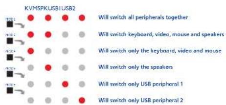
1 Optional: If you need to selectively switch some of your peripherals, press the MODE button repeatedly to change the switching mode:
Note: If an indicator flashes, it signifies that the respective peripheral is currently switched to another computer channel.
2 Press the COMPUTER button repeatedly to select the required computer channel.

To select a computer using hotkeys
Using hotkey combinations, you can quickly switch the keyboard, video monitor(s), mouse and speakers and USB peripherals to any computer channel. There are two mains ways to use hotkeys: Standard and Additional.
Standard hotkey press combinations
The standard hotkey press combinations allow you to change channels with the minimum of keypresses:
1 Simultaneously press and hold Carld (other hotkeys, if altered).
2 While still holding Carld, please the number key of the required channel address (or the TAB key), then release all of the keys.
Note: The numbers on your keyboard's numeric keypad are not valid, use only the numeral keys above the QWERTY section.
The ports (KVM, audio and/or USB) that are switched using this method depend upon the switching mode that is currently set using the front panel buttons.
The range of standard hotkey combinations are as follows:
Note: If your hotkeys have been changed, substitute them for Carlo in Alt the examples given here.
Ctrl Alt Selects channel 1
Ctrl Alt 2 Selects channel 2
Ctrl Alt Selects channel 3
Ctrl Alt Selects channel 4
Ctrl Alt Isolates the user console from all channels
Ctrl Alt Selects the next channel (see note
What are hotkeys?
The card key when pressed in combination are called 'hotkeys' and they signal to the AV4PRO-VGA unit that you wish to control it, rather than the computer. However, if these particular hotkeys clash with another device or program, you can change them to a different combination within the Configuration menu.
Additional hotkey press combinations
In addition to the standard hotkey press combinations (shown left), you can also add additional keypresses in order to determine which peripherals are switched:
1 Simultaneously press and hold Ctrl d . Alt
2 Press and release a command key:
to switch all peripherals
t switch only the keyboard, video and mouse
tswitch only the speakers
tswitch only USB1 and USB2
3 Press and release the required channel number (1b using only the keys above the QWERTY section).
4 Release Ctrlnd : Alt
The appropriate peripherals will change to the chosen channel.
Note: Regardless of which peripherals were switched, the front panel indicators will continue to show the switching mode that was last determined using the front panel controls.
Choosing which computers are accessed when using hot keys + tab
The computer channels that are visited when you use the hot keys + tab (or mouse buttons/autoscan) are determined by a setting within the Configuration menu:
1 Enter the Configuration menu.
2 Press U and then press either:
⑦ to choose Cycle all ports, or
8 to choose Cycle only active ports
3 Press Entercept the setting and return to the main menu section.
4 Press E and then Enterxit the menu and save changes.

To select a computer using the mouse buttons
Using the mouse buttons, you can quickly switch the keyboard, mouse, video monitor(s), speakers and/or USB peripherals to any computer channel. Note: These procedures work only with three-button or IntelliMouse devices and only if the 'Mouse Switching' option has been enabled.
To select a computer using the mouse buttons
1 Hold down the middle button (or scroll wheel) of the mouse.
2 Click the left mouse button to increment the channel number or click the right mouse button to decrement the channel. When the correct channel is reached, release the middle button.
When using this method of switching:
- The computer channels that are visited depend upon the configuration menu setting (see note ).
- The ports (KVM, audio and/or USB) that are switched using this method depend upon the switching mode that is currently set using the front panel buttons.
Choosing which computers are accessed when using mouse buttons
The computer channels that are visited when you use the mouse buttons (or hotkeys + tab/autoscan) are determined by a setting within the Configuration menu:
1 Enter the Configuration menu.
2 Press U and then press either:
7 to choose Cycle all ports, or
8 to choose Cycle only active ports
3 Press Entercept the setting and return to the main menu section.
4 Press E and then enterit the menu and save changes.

To lock access to the computers
When privacy is required, you can lock access to the connected computers via the unit.
To lock the unit
1 Simultaneously press and hold card (other hotkeys, if altered).
2 While still holding card, press. L
The display will show (providing a valid password has been previously set). You will not be able to access any computers until the password is correctly entered.
To unlock the unit
- When prompted, enter the correct password and press
To set a new password
1 Enter the Configuration menu.
2 Press P and then Enter display will show
3 Enter a new password and then Enter
The password is not case sensitive and can be any combination of key strokes, including the function keys, but excluding the Num Lock, Caps Lock, Scroll Lock and keys. If your keyboard has special media keys, these also cannot be used as part of the password.
When you have typed in your password, press to store it. Don't worry if you type the password incorrectly, you can always re-enter configure mode and set the password again.
4 Press E and then Enter to exit the menu and save changes.
To cancel the password
1 Enter the Configuration menu.
2 Press P and then Entag display will show
3 Press Ento remove the existing password.
4 Press Find then Enter to exit the menu and save changes.
If you forget the password
To clear an existing password: Connect the OPTIONS port of the unit to the serial port of a computer and transmit the text clrpwd to the unit.

Autoscanning
When enabled, the autoscan mode switches between the connected computers in sequence. This is useful to allow you to sample activity among the connected computers.
Two scanning modes are available:
- Cycle all ports – This mode visits, in turn, to each connected computer. This mode should be used with care due to the reasons given in the warning below. To prepare for this autoscan mode, choose U within the configuration menu (see right).
- Cycle only active ports – Only computer ports where an active computer is detected will be viewed. This mode avoids blank screens from being displayed and helps to prevent the viewing monitor from entering a power-down state on every scan cycle.
Additionally, when this mode is selected, whenever you use either the mouse buttons or hot keys + tab to change channels, only computers that are active will be visited. To prepare for this autoscan mode, choose ⬆ ⬇ within the configuration menu (see right).
WARNING: Many monitors are fitted with automatic power saving relays that switch off after a few seconds when connected to an inactive computer. If you are using such a monitor, do not use the 'Cycle all ports' mode. Continual switching on and off of the monitor's relay will eventually damage the monitor.
Seven autoscan periods are available (the time spent viewing each computer) ranging from 2 seconds to 5 minutes. To prepare the autoscan period, choose T and then a b within the configuration menu (see right).
To start autoscanning mode, press Ctrl Auto X keyboard.
To select an autoscan mode
1 Enter the Configuration menu.
2 Press ▶ and then press either:
• 7 to choose Cycle all ports, or
• 8 to choose Cycle only active ports
3 Press Enter accept the setting and return to the main menu section.
4 Press E and then Eto exit the menu and save changes. Note: The setting of this option also affects which computers are visited when the channel is changed using the mouse buttons or hot key + tab.
To select an autoscan period
1 Enter the Configuration menu.
2 Press T and then press either:
1) to choose Autoscan disabled,
② to choose 2 seconds,
3 to choose 5 seconds,
4 to choose 7 seconds,
5 to choose 15 seconds,
6 to choose 30 seconds,
⑦ to choose 1 minute, or
8 to choose 5 minutes.
3 Press Enter accept the setting and return to the main menu section.
4 Press E and then Enterit the menu and save changes.
To start autoscanning
• On the keyboard, pressCtrl Alt X
Notes:
During autoscanning, mouse switching, hot key + tab and interactivity with the computers are all disabled.
During autoscanning, only the KVM and speaker ports are switched to each visited computer channel, the two USB device ports remain connected to their currently selected channels.
To stop autoscanning
You can stop the autoscanning process in either of the following ways:
- Press the COMPUTER button on the front panel, or
- Select a specific channel using the hot keys + channel number.

Further information
This chapter contains a variety of information, including the following:
• Getting assistance - see right
• Appendix 1 – Supported video modes
• Appendix 2 – Cable pin-outs
Getting assistance
If you are still experiencing problems after checking the information contained within this guide, then please refer to the Support section of our website:
www.adder.com

Appendix 1 - Default EDID video modes
The following digital video modes are defined within the default EDID information held by the AV4PRO-VGA units. This information is used only if no new EDID information is made available by the attached video monitor(s). The AV4PRO-VGA units support video resolutions and refresh rates in excess of those listed here.
1024 x 768p at 60Hz Native/preferred timing
720 x 400p at 70Hz IBM VGA
720 x 400p at 88Hz IBM XGA2
640 x 480p at 60Hz IBM VGA
640 x 480p at 67Hz Apple Mac II
640 x 480p at 72Hz VESA
640 x 480p at 75Hz VESA
800 x 600p at 56Hz VESA
800 x 600p at 60Hz VESA
800 x 600p at 72Hz VESA
800 x 600p at 75Hz VESA
832 x 624p at 75Hz Apple Mac II
1024 x 768i at 87Hz IBM
1024 x 768p at 60Hz VESA
1024 x 768p at 70Hz VESA
1024 x 768p at 75Hz VESA
1280 x 1024p at 75Hz VESA
1152 x 870p at 75Hz Apple Mac II
1600 x 1200p at 60Hz VESA STD
1680 x 1050p at 60Hz VESA STD
1360 x 765p at 60Hz VESA STD
1360 x 768p at 60Hz
1440 x 900p at 60Hz VESA STD
1280 x 720p at 60Hz VESA STD
1920 x 1080p at 60Hz VESA STD

Appendix 2 - Cable pin-outs
The OPTIONS port uses a 10p10c socket which can accommodate both 10p10c connectors as well as the much more common 8p8c connectors, which are used on Ethernet leads and patch cables. The pin-outs are listed in this section for both types of connector.
Serial remote control and flash upgrade cable (8p8c)

Serial remote control and flash upgrade cable (10p10c)

Multi-head synchronisation cable (8p8c)
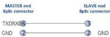
flowchart
graph LR
    A["MASTER end 8p8c connector"] --> B["TXDRXD"]
    A --> C["GND"]
    D["SLAVE end 8p8c connector"] --> E["3"]
    D --> F["2"]
    D --> G["GND"]
Multi-head synchronisation cable (10p10c)

flowchart
graph LR
    A["MASTER end 10p10c connector"] --> B["TXDRXD"]
    A --> C["GND"]
    D["SLAVE end 10p10c connector"] --> E["4"]
    D --> F["3"]
    D --> G["GND"]


www.adder.com
Documentation by:

www.ctxd.com
© 2019 Adder Technology Limited
All trademarks are acknowledged.
Part No. MAN-AV4PRO-VGA • Release 1.3

Index
A
Audio connection 7 Autoscanning 22
B
Brackets fitting 6
C
Cable pin-outs 25
Channel select input lines 10
Channel selection codes 10
Computer
connection 8
ports 4
selecting 18
Configuration 13
Connections 7
computer system 8
multiple video heads 11
user console 7
E
EDID information 12 default video modes 24 Emulated switching 3 Enumerated switching 3 External control 10
F
Firmware upgrade 16 Front panel switching 18
H
Host computer connection 8 Hotkeys changing 14 selecting computers 19 what are they? 19
1
Indicators 4
K
Keyboard connection 7 KVM 2
L
Lock the unit 21
M
Mounting 6
Mouse
connection 7
Multiple units synchronising 11
Multiple video head connections 11
0
Operation 18
Options port 4 behaviour setting 14 pinout 10 speed setting 14
P
Parts supplied and extra 5 Password setting & entering 21 Peripherals connecting 7
R
Rack mounting 6 Remote control by computer 10,14 by RC4 unit 9 Remote wakeup 2 RS-232 serial switching commands 10
s
Selecting computers with front panel 18 with hotkeys 19 with mouse buttons 20 Serial port
settings for control 10 Speakers connection 7 Supplied items 5 Switching 18 by input lines 10 by RS-232 serial 10 Switching mode setting a default 15
T
Troubleshooting 23 True Emulation 2,3
U
Unlock the unit 21 Upgrade firmware 16 USB device connection 7 USB Remote wakeup 2 USB switching emulation 3 enumeration 3 True Emulation 2,3 User console 4
v
Video modes 24 Video port connection 7


- Installation
- Configuration
- Operation
- Further information
- Index
- Introduction
- Multiscreen versions
- Intelligent display information
- Multiple switching
- True Emulation
- USB Remote wakeup
- What is True Emulation?
- Enumerated USB switching
- Emulated USB switching
- AV4PRO-VGA features - front and rear
- Options port
- Mounting
- Connections
- User console
- To connect peripherals to the user console
- Computer systems
- To connect a computer system
- Power in connection
- To connect the power supply
- Optional RC4 remote control
- To connect the remote control
- Channel switching by external control
- OPTIONS port pinout
- To connect a computer or device for remote control
- Control by RS-232 serial
- Serial port parameter settings
- Serial port channel selection codes
- Control by channel select input lines
- Synchronising multiple units
- Managing EDID video display information
- EDID Emulation
- Refreshing EDID information during use
- To refresh EDID information during use
- Using stored EDID information only
- To use the stored EDID information at the power up
- Using the configuration menu
- To use the configuration menu
- To exit the configuration menu and save changes
- To exit the configuration menu without saving
- General configuration
- Changing hotkeys
- To change the hotkeys
- Mouse switching
- To enable/disable mouse switching
- OPTIONS port speed
- To change the OPTIONS port speed
- OPTIONS port channel control behaviour
- To define the OPTIONS port behaviour
- Switching mode
- To set the default switching mode
- Miscellaneous functions
- To refresh EDID information from the monitor
- To reset configuration to factory defaults
- To show the current firmware version
- To set a new password
- Performing upgrades
- Items required to perform an upgrade
- To use the KVM Firmware Uploader utility
- - Obtain and run the KVM Firmware Uploader.
- - Power off the AV4PRO-VGA unit
- - Connect the upgrade computer to the AV4PRO-VGA unit
- - Invoke upgrade mode
- - Run the KVM Firmware Uploader utility
- - Query the AV4PRO-VGA unit
- - Select the upgrade file to be used
- - Commence the upgrade
- - Cycle the power
- Issues to consider when performing flash upgrades
- Selecting a computer
- To select a computer using the front panel
- To select a computer using hotkeys
- Standard hotkey press combinations
- What are hotkeys?
- Additional hotkey press combinations
- Choosing which computers are accessed when using hot keys + tab
- To select a computer using the mouse buttons
- Choosing which computers are accessed when using mouse buttons
- To lock access to the computers
- To lock the unit
- To unlock the unit
- To cancel the password
- If you forget the password
- Autoscanning
- To select an autoscan mode
- To select an autoscan period
- To start autoscanning
- To stop autoscanning
- Getting assistance
- Appendix 1 - Default EDID video modes
- Appendix 2 - Cable pin-outs
- A
- B
- C
- E
- F
- H
- 1
- K
- L
- M
- 0
- P
- R
- s
- T
- U
- v
Brand : Adder
Model : AV4PRO-VGA
Category : KVM Switch