
STVS421HDPIP - Router StarTech.com - Free user manual and instructions
Find the device manual for free STVS421HDPIP StarTech.com in PDF.


| Product Type | 4x1 HDMI Matrix Switch with Picture-in-Picture |
| Model | STVS421HDPIP / VS421HDPIP |
| Brand | StarTech.com |
| Input Ports | 4 x HDMI (female) |
| Output Ports | 1 x HDMI (female) |
| Maximum Resolution | 1080p (1920x1080) at 60 Hz |
| Supported Resolutions | 480p, 576p, 720p, 1080p (various frame rates), 1024x768, 1280x800, 1280x1024, 1366x768, 1440x900, 1600x900, 1600x1200, 1680x1050, 1920x1200, NATIVE (EDID) |
| Video Modes | Full Screen, Dual Picture-in-Picture, All Input Display (4-way split) |
| Control Interfaces | Front panel buttons, IR remote, RS-232 (DB9), Ethernet (web GUI) |
| On-Screen Display (OSD) | Yes, for advanced settings (image adjust, window setup, chroma key, etc.) |
| Audio Selection | Selectable from any HDMI input (1-4) |
| Power Adapter | Included universal adapter (NA/UK/EU plugs), input 100-240V AC |
| Compliance | FCC Class B, ICES-003 |
| Warranty | 2 years |
| Technical Support | Lifetime (24/7) via website |
| Package Contents | 1x Switch, 1x Remote Control, 2x Mounting Brackets, 1x Power Adapter, 1x Manual |
| Mounting | Rackmount brackets included (1U form factor) |
| RS-232 Baud Rate | 115200 bps |
| Network Control | DHCP or Static IP, web GUI for remote operation |
| Special Effects | Chroma key, Mirror, Fade In/Out, Rotation (90°/180°) |
| Maintenance | Clean with a dry, soft cloth; avoid liquids and moisture |
| Safety | Use only the supplied power adapter; keep away from water and heat |
| Repairability / Spare Parts | Remote control and power adapter available as spares; unit is not user-serviceable |
Frequently Asked Questions - STVS421HDPIP StarTech.com
User questions about STVS421HDPIP StarTech.com
0 question about this device. Answer the ones you know or ask your own.
Ask a new question about this device
Download the instructions for your Router in PDF format for free! Find your manual STVS421HDPIP - StarTech.com and take your electronic device back in hand. On this page are published all the documents necessary for the use of your device. STVS421HDPIP by StarTech.com.
USER MANUAL STVS421HDPIP StarTech.com
4x1 HDMI Matrix Switch with Picture-in-Picture – 1080p
VS421HDPIP

*actual product may vary from photos
For the most up-to-date information, please visit: www.startech.com
FCC Compliance Statement
This equipment has been tested and found to comply with the limits for a Class B digital device, pursuant to part 15 of the FCC Rules. These limits are designed to provide reasonable protection against harmful interference in a residential installation. This equipment generates, uses and can radiate radio frequency energy and, if not installed and used in accordance with the instructions, may cause harmful interference to radio communications. However, there is no guarantee that interference will not occur in a particular installation. If this equipment does cause harmful interference to radio or television reception, which can be determined by turning the equipment off and on, the user is encouraged to try to correct the interference by one or more of the following measures:
• Reorient or relocate the receiving antenna.
- Increase the separation between the equipment and receiver.
- Connect the equipment into an outlet on a circuit different from that to which the receiver is connected.
- Consult the dealer or an experienced radio/TV technician for help
This device complies with part 15 of the FCC Rules. Operation is subject to the following two conditions: (1) This device may not cause harmful interference, and (2) this device must accept any interference received, including interference that may cause undesired operation.
Changes or modifications not expressly approved by StarTech.com could void the user's authority to operate the equipment.
Industry Canada Statement
This Class B digital apparatus complies with Canadian ICES-003.
Use of Trademarks, Registered Trademarks, and other Protected Names and Symbols
This manual may make reference to trademarks, registered trademarks, and other protected names and/or symbols of third-party companies not related in any way to StarTech.com. Where they occur these references are for illustrative purposes only and do not represent an endorsement of a product or service by StarTech.com, or an endorsement of the product(s) to which this manual applies by the third-party company in question. Regardless of any direct acknowledgement elsewhere in the body of this document, StarTech.com hereby acknowledges that all trademarks, registered trademarks, service marks, and other protected names and/or symbols contained in this manual and related documents are the property of their respective holders.
Table of Contents
Product Diagram....1
Front View .... 1
Rear View....1
Introduction......2
Packaging Contents 2
System Requirements....2
Specifications....3
Technical Support 4
Warranty Information......4
Introduction
Packaging Contents
• 1x 4-Port HDMI Switch w/PAP
- 1x Remote Control
- 2x Mounting brackets
• 1x Universal Power Adapter (NA/UK/EU)
• 1x Instruction Manual
System Requirements
- Up to 4 x HDMI-enabled Video Source Devices (i.e. computer, Blu-ray Player)
- Up to 1x HDMI-enabled Display Devices (i.e. television, projector)
- Up to 5x M/M HDMI cables for your display, and video sources
Product Diagram
Front View

- IR Sensor
- Power Button / LED
- Menu Button / LED
- Menu Operation Buttons / LEDs
- Input Selection Buttons / LEDs
- Picture-in-Picture Selection Buttons / LEDs (A-H)
- All Display Operation Buttons / LEDs (E-H)
Back View

- HDMI Input Ports
- HDMI Output Port
- LAN Port
- USB Service Port
- DB9 Service Port
- Power Adapter Port
Hardware Installation
- Connect up to four HDMI cables (not included) from each of your HDMI video source devices (i.e. computers, Blu-ray Players) to each of the HDMI input ports on the matrix switch.
- Connect up to an HDMI cable (not included) from the HDMI output port on the matrix switch to the HDMI input port on your display device (i.e. televisions, projectors).
- Connect the power adapter from an available power outlet to the Power adapter port the Matrix switch.
- (Optional) If you would like to control your Matrix Switch over your network, connect a network cable (not included) from the LAN port on the matrix switch to an available LAN port on your network device.
Hardware Operation
Full Screen Display Operation
- Press the Output select button (that corresponds with the numbered output display) you wish to select.
- Your selected video input will now be displayed on your video output.
Dual Mode Picture-in-Picture Operation
- Select your primary video input, by pressing the Output select button (that corresponds with the numbered output display) you wish to select.
- Press the Picture-in-Picture Selection Button (A through D) that corresponds with your desired secondary video output.
Note: A through D represents video Inputs 1 through 4 respectively.
- Your secondary display is displayed along with your primary display.
All Input Display Operation
- Press the All Display button (E through H) that corresponds with your desired display configuration.
- All Video sources will now display in your desired video output.
Note: The Audio output will be the source device connected to Input 1.
On Screen Display Menu
The OSD menu gives you access to advanced functionality. The below table lists each OSD menu option. The description field outlines the functionality of each menu selection.
| Main Menu Sub Menu | Sub Menu | Adjustments Default Description | |||
| I/O Setup | Output Resolution | 480P, 579P,720P50/60,1080P24/25/30/50/60,1024x768,1280x800,1280x1024,1366x768,1440x900,1600x900,1600x1200,1680x1050,1920x1200,NATIVE | 720p60 | Enables youto select yourdesired outputresolution. | |
| Menu Back | Returns tomain menu. | ||||
| OSD Settings | Info display On/Off Off | ||||
| H Offset 0~20 (5) 5 Enables you | to adjust thespecifiedattributes inrelation tothe On theScreen displaypositioningand operation.Note: TIMEOUT=OFF meansMENU andINFO willcontinueshowing onthe screen | ||||
| V Offset 0~20 5 | |||||
| Timeout Off~50 Off | |||||
| Gain 0~10 2 | |||||
| Menu Back | Returns toprevious menu. | ||||
| Menu Exit | Returns tomain menu. | ||||
| Image Adjust | Brightness Adjust | CH 1 0~100 50 | Enables you to adjust the specified attributes for your desired picture quality. | ||
| CH 2 0~100 50 | |||||
| CH 3 0~100 50 | |||||
| CH 4 0~100 50 | |||||
| Contrast Adjust | CH 1 0~100 50 | ||||
| CH 2 0~100 50 | |||||
| CH 3 0~100 50 | |||||
| CH 4 0~100 50 | |||||
| Value Reset | Restores default image settings. | ||||
| Menu Exit | Returns to Main Menu. | ||||
| Window Setup | Channel 1 Select | Size | CH1 Wxxx Hxxx | Enables you to physically define the size of the video source on your display. | |
| Width Unit | |||||
| Width Ten | |||||
| Width Hundred | |||||
| Height Unit | |||||
| Height Ten | |||||
| Height Hundred | |||||
| Position | CH1 Hxxx Vxxx | Enables you to physically define the position of the video source on your display. | |||
| Horizontal Unit | |||||
| Horizontal ten | |||||
| Horizontal Hundred | |||||
| Vertical Unit | |||||
| Vertical Ten | |||||
| Vertical Hundred | |||||
| Window Setup | Channel 1 Select | Image Output | On/Off On | Enables or disables the output of the specific video source. | |
| Priority | CH1->4, CH2 ->3, CH 3->2, CH4->4 | CH1->4, CH2 ->3, CH 3->2, CH4->4 | Enables you to define the device priority for automatic switching. | ||
| Window Reset | Restores your default settings for the specified source device. | ||||
| Menu Exit | Returns to Main Menu. | ||||
| Channel 2 Select | Size | CH1 Wxxx Hxxx | Enables you to physically define the size of the video source on your display. | ||
| Width Unit | |||||
| Width Ten | |||||
| Width Hundred | |||||
| Height Unit | |||||
| Height Ten | |||||
| Height Hundred | |||||
| Position | CH1 Hxxx Vxxx | Enables you to physically define the position of the video source on your display. | |||
| Horizontal Unit | |||||
| Horizontal ten | |||||
| Horizontal Hundred | |||||
| Vertical Unit | |||||
| Vertical Ten | |||||
| Vertical Hundred | |||||
| Window Setup | Channel 2 Select | Image Output | On/Off On | Enables or disables the output of the specific video source. | |
| Priority | CH1->4, CH2 ->3, CH 3->2, CH4->4 | CH1->4, CH2 ->3, CH 3->2, CH4->4 | Enables you to define the device priority for automatic switching. | ||
| Window Reset | Restores your default settings for the specified source device. | ||||
| Menu Exit | Returns to Main Menu. | ||||
| Channel 3 Select | Size | CH1 Wxxx Hxxx | Enables you to physically define the size of the video source on your display. | ||
| Width Unit | |||||
| Width Ten | |||||
| Width Hundred | |||||
| Height Unit | |||||
| Height Ten | |||||
| Height Hundred | |||||
| Position | CH1 Hxxx Vxxx | Enables you to physically define the position of the video source on your display. | |||
| Horizontal Unit | |||||
| Horizontal ten | |||||
| Horizontal Hundred | |||||
| Vertical Unit | |||||
| Vertical Ten | |||||
| Vertical Hundred | |||||
| Window Setup | Channel 3 Select | Image Output | On/Off On | Enables or disables the output of the specific video source. | |
| Priority | CH1->4, CH2 ->3, CH 3->2, CH4->4 | CH1->4, CH2 ->3, CH 3->2, CH4->4 | Enables you to define the device priority for automatic switching. | ||
| Window Reset | Restores your default settings for the specified source device. | ||||
| Menu Exit | Returns to Main Menu. | ||||
| Channel 4 Select | Size | CH1 Wxxx Hxxx | Enables you to physically define the size of the video source on your display. | ||
| Width Unit | |||||
| Width Ten | |||||
| Width Hundred | |||||
| Height Unit | |||||
| Height Ten | |||||
| Height Hundred | |||||
| Position | CH1 Hxxx Vxxx | Enables you to physically define the position of the video source on your display. | |||
| Horizontal Unit | |||||
| Horizontal ten | |||||
| Horizontal Hundred | |||||
| Vertical Unit | |||||
| Vertical Ten | |||||
| Vertical Hundred | |||||
Window Setup
| Channel 4Select | Image Output | On/Off On | Enables or disables the output of the specific video source. | |
| Priority | CH1->4, CH2 ->3, CH 3->2, CH4->4 | CH1->4, CH2 ->3, CH 3->2, CH4->4 | Enables you to define the device priority for automatic switching. | |
| Window Reset | Restores your default settings for the specified source device. | |||
| Menu Exit | Returns to Main Menu. | |||
| Label Select | VIDEO 1 | Enables you to specify a label for each video output. | ||
| VIDEO 2 | ||||
| VIDEO 3 | ||||
| VIDEO 4 | ||||
| Menu Exit | Returns to previous menu. | |||
| Favours Store | FAV 1 Store | Enables you to access the save and recall features from the OSD menu. | ||
| FAV 2 Store | ||||
| FAV 3 Store | ||||
| FAV 4 Store | ||||
| Menu Exit | Returns to previous menu. | |||
| Menu Exit | Returns to Main Menu. | |||
Window Convert
| Channel 1 Convert | Mirror On/Off Off | Enables you to mirror the specified video source on your display. | ||
| Fade In-Out | Off/1.0/1.1/1.2 Convert /1.3/1.4 /1.5/1.6/1.7/1.8/ 1.9/2.0/2.1/2.2/ 2.3/2.4/2.5/2.6/ 2.7/2.8/2.9/3.0 | Off | Enables you to implement transition effects while switching between video sources. | |
| Rotation | R90/L90/Up-Side Down180/Off | Off | Enables you to rotate the video source on your display. | |
| Window Reset | Restores default Convert settings for the specified display. | |||
| Menu Exit | Returns to previous menu. | |||
| Channel 2 Convert | Mirror | Enables you to mirror the specified video source on your display. | ||
| Fade In-Out | Off/1.0/1.1/1.2 Convert /1.3/1.4 /1.5/1.6/1.7/1.8/ 1.9/2.0/2.1/2.2/ 2.3/2.4/2.5/2.6/ 2,7/2.8/2.9/3.0 | Off | Enables you to implement transition effects while switching between video sources. | |
Window Convert
| Channel 2 Convert | Rotation | R90/L90/Up-Side Down180/Off | Off | Enables you to rotate the video source on your display. |
| Window Reset | Restores default Convert settings for the specified display. | |||
| Menu Exit | Returns to previous menu. | |||
| Channel 3 Convert | Mirror | Enables you to mirror the specified video source on your display. | ||
| Fade In-Out | Off/1.0/1.1/1.2 Convert /1.3/1.4 /1.5/1.6/1.7/1.8/ 1.9/2.0/2.1/2.2/ 2.3/2.4/2.5/2.6/ 2.7/2.8/2.9/3.0 | Off | Enables you to implement transition effects while switching between video sources. | |
| Rotation | R90/L90/Up-Side Down180/Off | Off | Enables you to rotate the video source on your display. | |
| Window Reset | Restores default Convert settings for the specified display. | |||
Window Convert
| Channel 3 Convert | Menu Exit | Returns to previous menu. | ||
| Channel 4 Convert | Mirror | Enables you to mirror the specified video source on your display. | ||
| Fade In-Out | Off/1.0/1.1/1.2 Convert /1.3/1.4 /1.5/1.6/1.7/1.8/1.9/2.0/2.1/2.2/2.3/2.4/2.5/2.6/2.7/2.8/2.9/3.0 | Off | Enables you to implement transition effects while switching between video sources. | |
| Rotation | R90/L90/Up-Side Down180/Off | R90/L90 / Up-Side Down180 /Off | Enables you to rotate the video source on your display. | |
| Window Reset | Restores default Convert settings for the specified display. | |||
| Chromakey Setup | Minimum For R | 000~255 0 | The Chromakey Setup section enables you to isolate a particular color for chroma keying special effects. | |
| Maximum For R | 000~255 15 | |||
| Minimum For G | 000~255 0 | |||
| Maximum For G | 000~255 15 | |||
| Minimum For B | 000~255 0 | |||
| Maximum For B | 000~255 15 | |||
| Switch Off | ||||
| Exit | Returns to main menu | |||
| Ethernet Setup | IP Mode Static/DHCP DHCP | Enables you to define Network communication protocols for remote operation. | ||
| Static Set IP/Mask/Gate | ||||
| Byte1 High | XXX 192 255 192 | 000~255 | ||
| Byte2 | XXX 168 255 168 | 000~255 | ||
| Byte3 XXX | 5 255 5 000~255 | |||
| Byte4 Low | XXX 159 0 254 | 000~255 | ||
| Re-Link No/Yes | ||||
| Exit | ||||
| Static/ DHCP IP | LINKED/NOT LINKED | |||
| Ethernet Setup | IP IP/Mask/Gate | |||
| Mask XXX.XXX.XXX.XXX | ||||
| Gate XXX.XXX.XXX.XXX | ||||
| Mac XXX.XXX.XXX.XXX | ||||
| Sink HDMI / DVI | ||||
| Information | Model | Enables you to view the technical specifications of the specified attributes. | ||
| Native | ||||
| F/V Version | ||||
| Menu Exit Closes OSD menu. | ||||
IR Remote Control Operation
An IR remote control is included with the VS421HDPIP for hassle-free remote operation. Please review the legend below for a detailed description of each remote control function.

-
Power: Press this button to switch on the device or press it again to set it to standby mode.
-
Info: Press this button to show the device's firmware version.
-
Input CH 1\~4: Press these buttons to rotate HDMI 1\~4 input source on each
channel to be
- WA\~WH: Press these hot keys to select the screen setting where WA\~WD are display a full screen of each channel and WE\~WH are a different combination of a full screen setting with all 4 channels.
Note: Functions are limited to Window A to D. The system will force to switch to Window A when operate under Window E\~H. - Mute: Press this button to disable the audio from HDMI output port.
- ▲▼▶◀ & OK: Press this buttons to scroll through the OSD selection and press OK to enter and confirm the setting.
- Menu: Press this button to enter into the OSD menu.
- Exit: Press this button to exit the OSD menu or the OSD settings.
- FAV. 1\~4: Press these buttons to bring up the customized screen settings.
- Fade-In-Out: Press this button to switch on or off the Fade-in-out function.
- Chromakey: Press this button to enter into Chroma function where CH 1 is the background and CH 2 is the top image.
- Mirror: Press this button to display the screen in mirror image.§
- Rotation: Press this button to rotate the image 90° left and right or 180° upside down.
- Audio 1\~4: Press these buttons to select audio from HDMI input source 1\~4.
RS232 Protocols
Baud Rate: 115200bps
Data Bit: 8 bits
Parity: None
Flow Control: None
Stop Bit: 1
RS232 Telent Commands
Note: All commands will be not executed unless followed with a carriage return (0x0D) and commands are case-sensitive.
| RESO 0~18 | SET OUTPUT RESOLUTION(0) 480p, (1) 576p, (2) 720p 50Hz, (3) 720p 60Hz, (4)1080p 24Hz, (5) 1080p 25Hz, (6) 1080p 30Hz, (7) 1080p50Hz, (8) 1080p 60Hz, (9) 1024x768 60Hz, (10) 1280x80060Hz, (11) 1280x1024 60Hz, (12) 1366x768 60Hz, (13)1440x900 60Hz, (14) 1600x900 60Hz, (15)1600x120060Hz, (16) 1680x1050 60Hz, (17)1920x1200 60Hz,(18) Native |
| OSDDIS 0/1 | ENABLE/DISABLE ONSCREEN DISPLAY(0) OFF, (1) ON |
| OSDH 0~20 | OSD H OFFSET0~20 |
| OSDV 0~20 | OSD V OFFSET0~20 |
| OSDTIME 0~50 | OSD TIMEOUT0~50 |
| OSDGAIN 0~10 | OSD GAIN VALUE0~10 |
| BRI 0~4 0~100 | SET BRIGHTNESS VALUE FOR CHANNEL(0) All,(1~4) CHANNEL, (0~100) VALUE |
| CON 0~4 0~100 | SET CONTRAST VALUE FOR CHANNEL PORT(0) All,(1~4) CHANNEL, (0~100) VALUE |
| SAT 0~4 0~100 | SET SATURTATION VALUE FOR CHANNEL PORT(0) All,(1~4) CHANNEL, (0~100) VALUE |
| HSIZE 1~4 0~X | SET HUE VALUE FOR CHANNEL PORT(0) All,(1~4) CHANNEL, (0~100) VALUE |
| HSIZE 1~4 0~X | SET IMAGE HORIZONTAL SIZE (1~4) CHANNEL,(0~X) X=HORIZONTAL PIXEL FOR CURRENT RESOLUTION |
| VSIZE 1~4 0~X | SET IMAGE VERTICAL SIZE (1~4) CHANNEL,(0~X) X=VERTICAL PIXEL FOR CURRENT RESOLUTION |
| HPOS 1~4 0~X | SET HORIZONTAL POSITION OF SPECIFIED CHANNEL (1~4) CHANNEL,(0~X) X=HORIZONTAL PIXEL FOR CURRENT RESOLUTION |
| VPOS 1~4 0~X | SET VERTICAL POSITION OF SPECIFIED CHANNEL (1~4) CHANNEL,(0~X) X=VERTICAL PIXEL FOR CURRENT RESOLUTION |
| IMAGE 1~4 0~1 | CHANNEL(S) OUTPUT ON/OFF (1~4) CHANNEL,(0/1) OFF/ON |
| PRI 1~4 1~4 | SET CHANNEL PRIORITY (1~4) CHANNEL,(1~4) PRIORITY |
| LABEL 1~4 XXX | ASSIGN A VIDEO NAME (1~4) VIDEO,(XXX) ABCEDFGH... |
| STORE 1~4 | SAVE THE CURRENT WINDOW STATE TO FAV. (1~4) FAV. |
| RECALL 1~12 | RECALL A WINDOW STATE(1) WINDOW A, (2) WINDOW B, (3) WINDOW C,(4) WINDOW D, (5) WINDOW E, (6) WINDOW F, (7)WINDOW G, (8) WINDOW H, (9) WINDOW FAV. 1, (10)WINDOW FAV. 2, (11) WINDOW FAV. 3,(12) WINDOWFAV. 4 |
| MIRROR 0/1 | ENABLE/DISABLE MIRROR EFFECT (0/1) OFF/ON |
| FADE 0~21 | ENABLE/DISABLE FADE EFFECTS(0) OFF, (1) 1.0 s, (2) 1.1 s, (3) 1.2 s, (4) 1.3 s, (5) 1.4 s,(5) 1.5 s, (6) 1.6 s, (7) 1.7 s, (8) 1.8 s, (9) 1.9 s, (10) 2.0 s,(11) 2.1 s, (12) 2.2 s, (13) 2.3 s, (14) 2.4 s,(15) 2.5 s, (16)2.6 s, (17) 2.7 s, (18) 2.8 s, (19) 2.9 s, (20) 3.0 s |
| ROTATE 0~3 | SET VIDEO ROTATION VIDEO TO PRESET POSITIONS (0) ROTATE OFF, (1) R90, (2)L90, (3) 180 |
| CHRC R/G/B | SET THE RGB COLOR RANGE FOR THE CHROMA KEY |
| MIN/MAX 0~255 | (R/G/B) COLOR CHANNEL(MIN/MAX) COLOR VALUE(0~15) SET PRESENT VALUE 0~255RBG MAX(0)15, (1)31, (2)47, (3)63, (4)79, (5)95,(6)111, (7)127,(8)143, (9)159, (10)175, (11)191, (12)207,(13)223,(14)239, (15)255RGB MIN(0)00, (1)16, (2)32, (3)48, (4)64, (5)80,(6)96, (7)112,(8)128, (9)144, (10)160, (11)176, (12)192,(13)208,(14)224, (15)240 |
| CHRSW 0/1 | SET THE CHROMA KEY ON/OFF(0) OFF, (1) ON |
| IPMODE 0/1 | SET IP MODE TO DHCP OR STATIC(0) DHCP, (1) STATIC |
| IPADD XXX.XXX. XXX.XXX | SET IP ADDRESS(XXX) 0~255 |
| MAADD XXX. XXX.XXX.XXX | SET SUBNET ADDRESS(XXX) 0~255 |
| GAADD XXX. XXX.XXX.XXX | SET GATEWAY ADDRESS(XXX) 0~255 |
| ETHTIME 0~6 | ETHERNET TIMEOUT(0) OFF, (1) 10 MINUTE, (2) 20 MINUTE, (3) 30 MINUTE,(4) 40 MINUTE, (5) 50 MINUTE, (6) 60 MINUTE |
| RELINK RELINK THE UNIT IN 2 SECONDS | |
| DEFAULT RESET THE UNIT TO FACTORY DEFAULTS | |
| VICH 1~4 0~4 | VIDEO CHANNEL COMMAND (1~4)VIDEO,(0) ALL CHANNEL OUTPUTS,(1~4) CHANNEL OUTPUTS |
| MUTE 0/1 | MUTE AUDIO(0) OFF, (1) ON |
| POW 0/1 | POWER THE UNIT ON/OFF(0) OFF, (1) ON |
| AUDIO 1~4 | CHANGE OUTPUT AUDIO TO SPECIFIEDSOURCE (1~4) AUDIO SOURCE |
| IMRE B/C/S/H | RESET THE IMAGE TO FACTORYDEFAULTS(B) BRIGHTNESS, (C) CONTRAST, (S)SATURATION, (H) HUE |
| PIRE | RESET THE UNIT PICTURE SETTINGS TOFACTORY |
| CHRE 0~4 DEFAULTS | |
| WICORE | RESET THE WINDOW CONVERT TOFACTORY DEFAULTS |
| RIPM SHOW CURRENT IP MODE | |
| IPCONFIG SHOW IP CONFIGURATION | |
| HELP | HELP PRINTS ALL AVAILABLE RS-232/TELNET COMMANDSTO THE SCREEN |
?
PRINTS ALL AVAILABLE RS-232/TELNET
COMMANDS
TO THE SCREEN
IP Operation Using Web Browser Before you begin:
• Power Status must be set to on, and source status must be unlocked
- Ensure step 5. of hardware Setup has been completed.
- Obtain the IP address of the VS421HDPIP using the OSD menu.
Access the following sub menu:
ETHERNET -> IP
Your IP address will be displayed next to IP.
Note: The switch supports DHCP and it is activated by default. As a result if you connect it to a piece of network equipment that supports DHCP your IP address will automatically change. If your network equipment does not support DHCP your default IP address will be 192.168.5.155
Access IP Operation Web GUI
- Open your web browser.
- In the address bar type the IP address obtained from your OSD menu, and press enter.
- The VS421HDPIP web GUI is now displayed.
Operate your VS421HDPIP using the Web GUI
The web GUI enables you to remotely operate your VS421HDPIP with basic and advanced functionality. The below sections outline the features and navigation of the Web GUI.
Operation Pane
The operation pane gives you a high level overview as well as access to basic switch operation. The Operation pane is always visible at the top of every page in the Web GUI.

The Information-in and information-out sections gives you an overview of the current connected video source and display devices.
The Status section enables you to power off the device.
The Source section enables you to select your desired mode as well as define which video source devices will be shown on each display.
The Save/Factory section enables you to save and action the customized input and output corresponding settings.
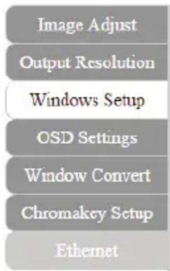
Advanced Menu
The Advanced menu is available on the left hand side of the GUI, and enables you to navigate between advanced sections of operation.
Descriptions outlining navigation as well as the available functionality for each tab are listed below.
Image Adjust
By default, the Image Adjust tab is the first window displayed when the web GUI is opened. If you would like to access the Image Adjust tab, and have navigated away from the Window, click Image Adjust tab from the side menu.
The Image Adjust tab enables you to define the specific attributes listed for optimal picture quality based on the requirements of your application.

Note: In Matrix mode, all four pictures adjust simultaneously.
In Dual/TV Wall mode, each picture can adjust individual and support individual last memory feature.
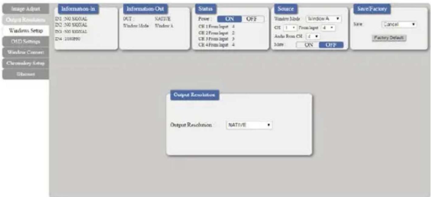
Output Resolution
To access the Output Resolution tab, click Output Resolution on the side menu.
The Output Resolution tab enables you to set your desired output resolution from the available drop down menu.
Notes:
• 1080i@50/60 are supported in Matrix mode only.
- Selecting NATIVE enables the VS421HDPIP to use EDID to determine the best output resolution automatically.
OSD Settings
To access the OSD settings tab, click OSD Settings on the side menu.
The OSD settings tab enables you to adjust the specified attributes in relation to the On the Screen display positioning and operation.

Note: TIMEOUT = OFF means MENU and INFO will continue showing on the Screen.
Window Convert
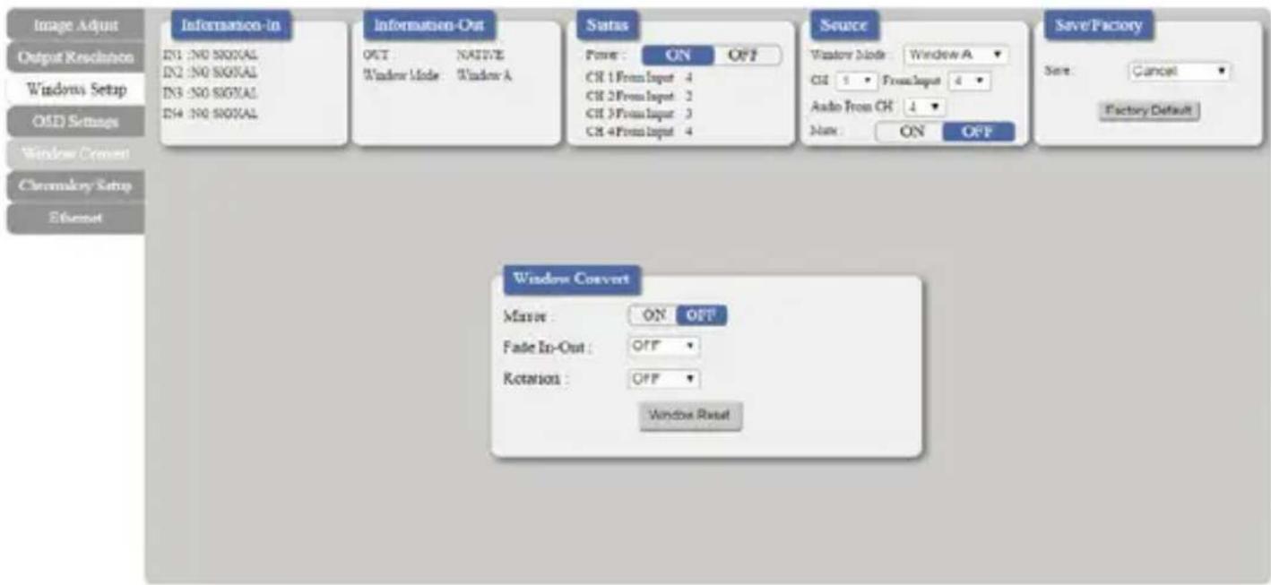
To access the Window Convert tab, click Window Convert on the side menu.
The Window Convert tab enables you to implement transition effects while switching between video sources.
Chromakey Setup
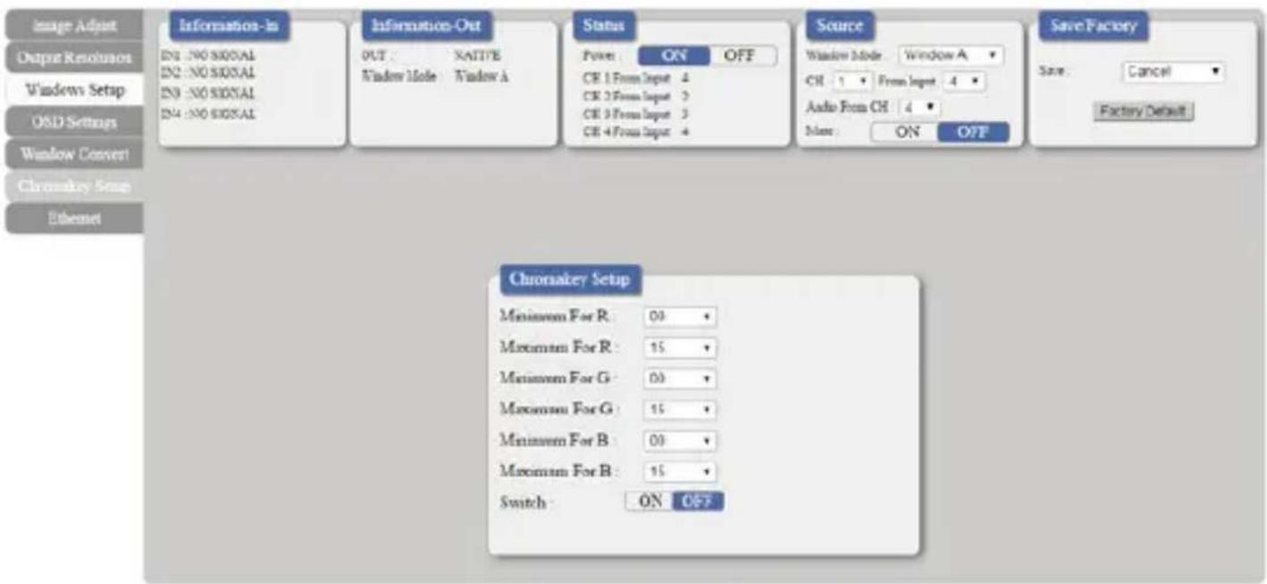
To access the Chromakey Setup tab, click Chromakey setup on the side menu.
The Chromakey Setup section enables you to isolate a particular color for chroma keying special effects.
Ethernet
To access the Ethernet tab, click Ethernet on the side menu.
The Ethernet section enables you to define Network communication protocols for remote operation.

Technical Support
StarTech.com's lifetime technical support is an integral part of our commitment to provide industry-leading solutions. If you ever need help with your product, visit www.startech.com/support and access our comprehensive selection of online tools, documentation, and downloads.
For the latest drivers/software, please visit www.startech.com/downloads
Warranty Information
This product is backed by a two year warranty.
In addition, StarTech.com warrants its products against defects in materials and workmanship for the periods noted, following the initial date of purchase. During this period, the products may be returned for repair, or replacement with equivalent products at our discretion. The warranty covers parts and labor costs only. StarTech.com does not warrant its products from defects or damages arising from misuse, abuse, alteration, or normal wear and tear.
Limitation of Liability
In no event shall the liability of StarTech.com Ltd. and StarTech.com USA LLP (or their officers, directors, employees or agents) for any damages (whether direct or indirect, special, punitive, incidental, consequential, or otherwise), loss of profits, loss of business, or any pecuniary loss, arising out of or related to the use of the product exceed the actual price paid for the product. Some states do not allow the exclusion or limitation of incidental or consequential damages. If such laws apply, the limitations or exclusions contained in this statement may not apply to you.
Hard-to-find made easy. At StarTech.com, that isn't a slogan. It's a promise.
StarTech.com is your one-stop source for every connectivity part you need. From the latest technology to legacy products — and all the parts that bridge the old and new — we can help you find the parts that connect your solutions.
We make it easy to locate the parts, and we quickly deliver them wherever they need to go. Just talk to one of our tech advisors or visit our website. You'll be connected to the products you need in no time.
Visit www.startech.com for complete information on all StarTech.com products and to access exclusive resources and time-saving tools.
StarTech.com is an ISO 9001 Registered manufacturer of connectivity and technology parts. StarTech.com was founded in 1985 and has operations in the United States, Canada, the United Kingdom and Taiwan servicing a worldwide market.


- 4X1 HDMI MATRIX SWITCH WITH PICTURE-IN-PICTURE – 1080P
- FCC COMPLIANCE STATEMENT
- INDUSTRY CANADA STATEMENT
- USE OF TRADEMARKS, REGISTERED TRADEMARKS, AND OTHER PROTECTED NAMES AND SYMBOLS
- TABLE OF CONTENTS
- PRODUCT DIAGRAM....1
- INTRODUCTION......2
- SPECIFICATIONS....3
- TECHNICAL SUPPORT 4
- WARRANTY INFORMATION......4
- INTRODUCTION
- PACKAGING CONTENTS
- SYSTEM REQUIREMENTS
- PRODUCT DIAGRAM
- FRONT VIEW
- BACK VIEW
- HARDWARE INSTALLATION
- HARDWARE OPERATION
- FULL SCREEN DISPLAY OPERATION
- DUAL MODE PICTURE-IN-PICTURE OPERATION
- ALL INPUT DISPLAY OPERATION
- ON SCREEN DISPLAY MENU
- IR REMOTE CONTROL OPERATION
- IP OPERATION USING WEB BROWSER BEFORE YOU BEGIN
- ACCESS IP OPERATION WEB GUI
- OPERATE YOUR VS421HDPIP USING THE WEB GUI
- IMAGE ADJUST
- OUTPUT RESOLUTION
- NOTES
- OSD SETTINGS
- WINDOW CONVERT
- CHROMAKEY SETUP
- ETHERNET
- TECHNICAL SUPPORT
- WARRANTY INFORMATION
- LIMITATION OF LIABILITY
Brand : StarTech.com
Model : STVS421HDPIP
Category : Router