VS491 - KVM switch ATEN - Free user manual and instructions
Find the device manual for free VS491 ATEN in PDF.

User questions about VS491 ATEN
0 question about this device. Answer the ones you know or ask your own.
Ask a new question about this device
Download the instructions for your KVM switch in PDF format for free! Find your manual VS491 - ATEN and take your electronic device back in hand. On this page are published all the documents necessary for the use of your device. VS491 by ATEN.
USER MANUAL VS491 ATEN
This equipment has been tested and found to comply with the limits for a Class B digital device, pursuant to Part 15 of the FCC Rules. These limits are designed to provide reasonable protection against harmful interference in a residential installation. This equipment generates, uses and can radiate radio frequency energy, and if not installed and used in accordance with the instruction manual, may cause interference to radio communications. However, there is no guarantee that interference will not occur in a particular installation. If this equipment does cause harmful interference to radio or television reception, which can be determined by turning the equipment off and on, the user is encouraged to try to correct the interference by one or more of the following measures:
◆ Reorient or relocate the receiving antenna;
◆ Increase the separation between the equipment and receiver;
- Connect the equipment into an outlet on a circuit different from that which the receiver is connected;
Consult the dealer or an experienced radio/television technician for help.
RoHS
This product is RoHS compliant.
SJ/T 11364-2006
The following contains information that relates to China.
You can register your product at our online support center:
- International – http://support.aten.com
- North America – http://www.aten-usa.com/product_registration
ONLINE SUPPORT
- Online technical support is available to ATEN customers through our support center:
- International – http://support.aten.com
- North America – http://www.aten-usa.com/support.
- Troubleshooting, Documentation (including online manuals), and Software Updates (firmware and drivers) are available at the ATEN website:
- International – http://www.aten.com
- North America – http://www.aten-usa.com
PACKAGE CONTENTS
The VS-291 / VS-491 2/4-Port Video Switch package contains the following items:
◆ 1 VS-291 / VS-491 2/4-Port Video Switch
◆ 1 DC 9V Power Adapter
◆ 1 User Manual*
Check to make sure that all the components are present and that nothing got damaged in shipping. If you encounter a problem, contact your dealer.
Read this manual thoroughly and follow the installation and operation procedures carefully to prevent any damage to the unit, and/or any of the devices connected to it.
* Features may have been added to the VS-291 / VS-491 since this manual was printed. Please visit our website to download the most up-to-date version of the manual.
Copyright © 2007 ATEN® International Co., Ltd.
Manual Part No. PAPE-1181-200G
Printing Date: 09/2007
ATEN and the ATEN logo are trademarks of ATEN International Co., Ltd. All rights
reserved. All other trademarks are the property of their respective owners.
OVERVIEW
The VS-291 / VS-491 Video Switches are control units that allow you to conveniently display the video output of two (VS-291) or four (VS-491) separate computer systems on a single monitor, thereby eliminating the unnecessary expense of purchasing a separate monitor for each computer. The units use electronic switching technology, rather than mechanical switching, for greater reliability and durability.
The VS-291 / VS-491 also saves on the space that additional monitors take up, as well as the extra power costs, and eliminates the inconvenience and wasted effort involved in constantly moving around from one computer to another.
FEATURES
Electronic switching for greater reliability and durability
◆ Display the output of two (VS-291) or four (VS-491) computers on a single monitor
- High resolution video – Up to 1920 x 1440; DDC; DDC2; DDC2B
◆ Supports, VGA, SVGA, XGA and Multisync Monitors
- Easy installation – No software required – No configuration necessary
◆ Computer selection via pushbutton switch
SYSTEM REQUIREMENTS
MONITORS
One VGA, SVGA, XGA, or Multisync compatible analog monitor, with a standard PC high-density cable with a standard HDB-15 male connector
COMPUTERS
The following equipment must be installed on each computer that is to be connected to the system:
One VGA, SVGA, XGA, or Multisync analog video card with a standard HDB-15 female connector per computer
CABLES
One video cable (with an HDB-15 male connector at each end) per computer
Note: 1. Video extender cables require a separate purchase. UL-2919 rated cable is recommended for the best video quality 2. This product is not suitable for CGA, EGA, or Monochrome type monitors using a digital video signal.
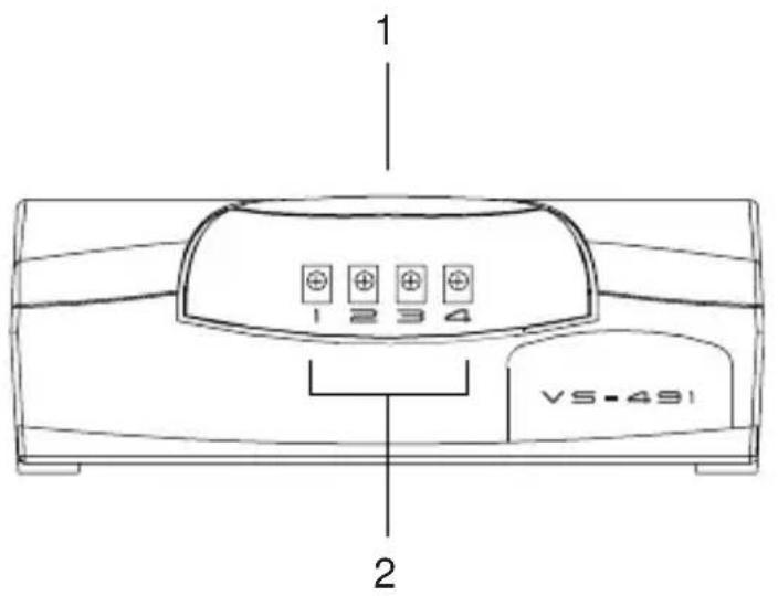
VS-491 FRONT VIEW
text_image
1 2 VS-491 2| No. | Component Description | |
| 1 | Port Selection Switch Press | this button to cycle the video focus among the computers. |
| 1 | Selected Port LEDs The nu | mbers correspond to the video ports on the back panel. A LED lights to indicate that its corresponding port is the one that has the video focus. |
Note: The VS-291 Front View is similar to the VS-491, except that it only has two Selected Port LEDs.
VS-491 REAR VIEW

text_image
MONITOR CPU 1 2 3| No. | Description Function | |
| 1 | Monitor Port The monitor cable plugs in here. | |
| 2 | Video Ports The video cables that connect to the computer video ports plug in here. | |
| 3 | Power Jack The Power Adapter cable plugs in here. |
Note: The VS-291 Rear View is similar to the VS-491, except it has only two Video Ports.
INSTALLATION

Make sure that all devices you will be installing are properly grounded.
Installation is simply a matter of plugging in cables. Refer to the diagrams as you follow the step-by-step directions below:
- Plug the monitor cable into the unit's monitor port.
- Plug one end of the video extender cable into any available video port on the unit's rear panel; plug the other end of the cable into the computer's video output port.
- Plug the power adapter into an AC source; plug the adapter's power cable into the unit's Power Jack. Power On all equipment.
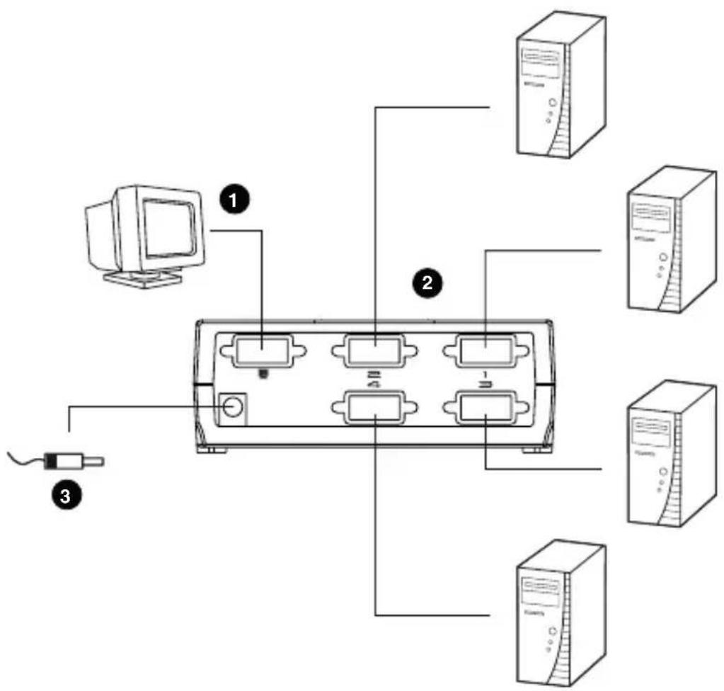
text_image
Diagram showing server rack connections with labeled components including computer, desktop, and ports| Function VS-291 | VS-491 | ||
| Connectors Output 1 x HDB-15 Female | |||
| LEDs (Selected Ports) 2 4 | |||
| Port Selection 1 x Pushbutton | |||
| Video 1920 x 1440 @ 60Hz; DDC; DDC2; DDC2B | |||
| Cable Distance 10 m (30 ft) | |||
| Signal Type VGA; SVGA; XGA, Multisync | |||
| Power Consumption | DC 9V; 0.9W (max.) | DC 9V; 1.35W (max.) | |
| Environment | Operating Temp. | 0–50°C | |
| Storage Temp. | -20–60°C | ||
| Humidity | 0–80% RH, Non-condensing | ||
| Physical Properties | Housing | Plastic/Metal | |
| Weight | 0.22 Kg | ||
| Dimensions L x W x H | 12.00 x 6.50 x 4.40 cm | ||
LIMITED WARRANTY
IN NO EVENT SHALL THE DIRECT VENDOR'S LIABILITY EXCEED THE PRICE PAID FOR THE PRODUCT FROM THE DIRECT, INDIRECT, SPECIAL, INCIDENTAL OR CONSEQUENTIAL DAMAGES RESULTING FROM THE USE OF THE PRODUCT, DISK OR ITS DOCUMENTATION.
The direct vendor makes no warranty or representation, expressed, implied, or statutory with respect to the contents or use of this documentation, and specially disclaims its quality, performance, merchantability, or fitness for any particular purpose.
The direct vendor also reserves the right to revise or update the device or documentation without obligation to notify any individual or entity of such revisions, or update. For further inquires please contact your direct vendor.