VM5404D - KVM switch ATEN - Free user manual and instructions
Find the device manual for free VM5404D ATEN in PDF.

User questions about VM5404D ATEN
0 question about this device. Answer the ones you know or ask your own.
Ask a new question about this device
Download the instructions for your KVM switch in PDF format for free! Find your manual VM5404D - ATEN and take your electronic device back in hand. On this page are published all the documents necessary for the use of your device. VM5404D by ATEN.
USER MANUAL VM5404D ATEN
Supported Video Matrix Switch 4
Installing the App .... 5
Main Page 6
Logging into the Video Matrix Switch 7
Logging into the Video Matrix Switch via Scan the Network ..... 8
Logging into the Video Matrix Switch via Select from History . . . 12
Logging into the Video Matrix Switch via Specify a Device ..... 14
Profile Tab 16
Control Tab 18
Switching the Video Inputs for the Video Output 20
Audio Tab 22
Specifying the Audio Inputs for the Digital and Analog Outputs . . 25
Settings Tab 28
Overview
The Video Matrix Control App is a free mobile app that allows you to switch profiles, audio inputs and video inputs, and also reminds you when any new firmware is available, all through a local area network to which the target Video Matrix Switch is connected. This mobile application is especially useful for profile and AV source switching when you do not have access to the Video Matrix Switch's front panel or the web interface.
Requirements
- The Video Matrix Control App supports the following operating systems:
| Mobile Operating System Supported Version | |
| iOS 12.0 or later | |
| Android 8.0 or later | |
Make sure to connect the mobile device to the network where your Video Matrix Switch is installed.
Supported Video Matrix Switch
| Supported Models |
| VM0404HB |
| VM0808HB |
| VM1600A |
| VM3200 |
| VM3250 |
| VM3404H |
| VM3909H |
| VM5404D |
| VM5404H |
| VM5808D |
| VM5808H |
| VM51616H |
| VM6404H |
| VM6404HB |
| VM6809H |
Installing the App
To install the Video Matrix Control App on a mobile device, do the following:
- From the mobile device, tap the App Store 🎨 or Google Play 🎩 icon.
- In the search box, type "Video Matrix Control App".
- Tap Video Matrix Control App and then download and install the app.
- Tap the app icon.
- Follow the on-screen instructions to connect to the target Video Matrix Switch by scanning the network, selecting from connection history, or specifying the device IP address and password.
Note:
- The Video Matrix Control App is designed to control one Video Matrix Switch device at a time.
If you cannot find the Video Matrix Switch, make sure that the Video Matrix Switch is connected to LAN and that the app is connected to the same LAN and then try again.
Or, scan the QR Code below to install the app.

text_image
Download on the App Store GET IT ON Google Play- From the mobile device, tap the Video Matrix Control App icon to launch the app.
Main Page
When logged in, the Video Matrix Control App defaults to the scanning page. Refer to the table below for an overview of the functions on each tab.
Note: The example used in the snapshots below is VM1600A.

text_image
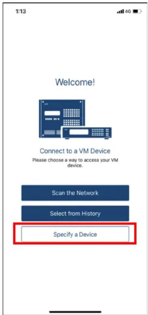
1:13 Welcome! Connect to a VM Device Please choose a way to access your VM device. Scan the Network Select from History Specify a Device| No. | Component Description | |
| 1 | Scan the Network | Tap to log in to a Video Matrix Switch by scanning the device in your network. |
| 2 | Select from History | Tap to log in to a Video Matrix Switch by selecting a device in the history list. |
| 3 | Specify a Device | Tap to log in to a Video Matrix Switch by specifying a device. |
Logging into the Video Matrix Switch
There are three ways to log into the Video Matrix Switch on Video Matrix Control App.
- Scan the Network – see Logging into the Video Matrix Switch via Scan the Network, page 8.
- Select from History – see Logging into the Video Matrix Switch via Specify a Device, page 14.
- Specify a Device – see Logging into the Video Matrix Switch via Specify a Device, page 14.
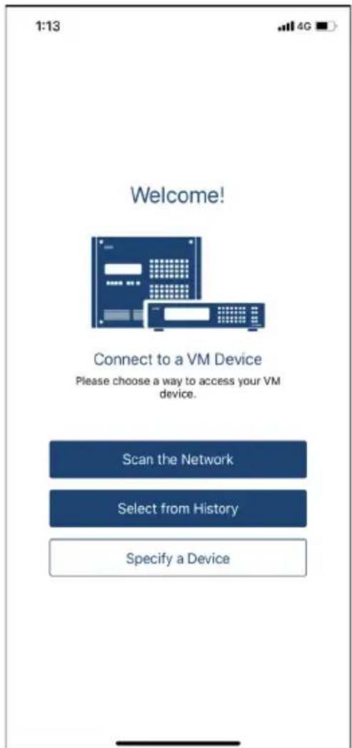
The below welcome page appears when the app is opened, and each log in methods are described below.
text_image
1:13 4G Welcome! Connect to a VM Device Please choose a way to access your VM device. Scan the Network Select from History Specify a DeviceLogging into the Video Matrix Switch via Scan the Network
To log in a Video Matrix Switch by scanning the network, do the following:
- Open the Video Matrix Control App, wait for the welcome page to appear, and tap Scan the Network.

text_image
1:13 Welcome! Connect to a VM Device Please choose a way to access your VM device. Scan the Network Select from History Specify a Device- Wait for the scanning to finish.

pie
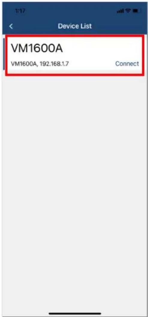
Searching...- The Video Matrix Switch and its IP address will show in the Device List.
Note: The example used in the snapshot below is VM1600A.
text_image
Device List VM1600A VM1600A, 192.168.1.7 Connect- Tap Connect to log into the Video Matrix Switch.
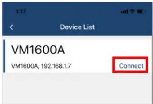
text_image
Device List VM1600A VM1600A, 192.168.1.7 ConnectATEN Video Matrix Control App
-
Enter the username and password, and then tap Connect.
-
Now you have successfully logged into the Video Matrix Switch.

text_image
1:19 OSD ZoneA Now Playing undefined Untitled Edit 01 02 03 04 05 06 07 08 09 10 11 12 13 14 15 16 Profile 01 Profile_01 4x4 Profile 02 Profile_02 4x4 Profile 03 Profile_03 4x4 Profile Create Auto SurgeryLogging into the Video Matrix Switch via Select from History
To log in a Video Matrix Switch by selecting from the history, do the following:
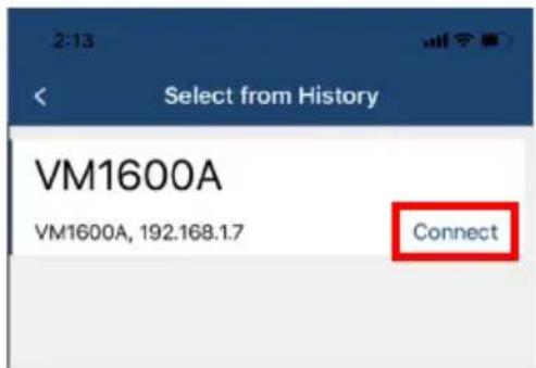
- Open the Video Matrix Control App, wait for the welcome page to appear, and tap Select from the History.

text_image
1:13 Welcome! Connect to a VM Device Please choose a way to access your VM device. Scan the Network Select from History Specify a Device- The Video Matrix Switch and its IP address will show in the history list, and tap Connect.
text_image
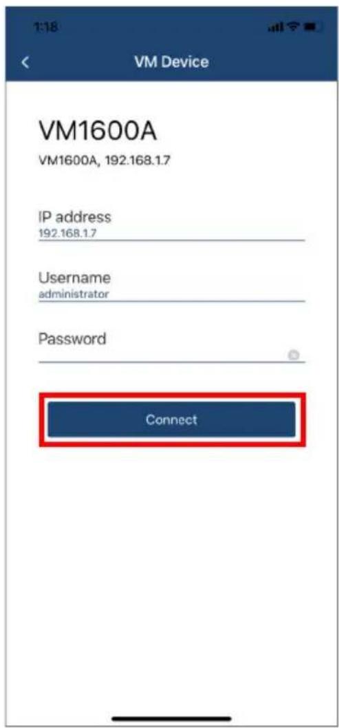
2:13 Select from History VM1600A VM1600A, 192.168.1.7 Connect- The pre-entered device's IP address, username, and password are remembered by the Video Matrix Control App. Simply tap Connect to log in, or tap on the ID address, username, and password to edit if its required.
text_image
VM1600A VM1600A, 192.168.1.7 IP address 192.168.1.7 Username administrator Password Connect- Now you have successfully logged into the Video Matrix Switch.
Logging into the Video Matrix Switch via Specify a Device
To log in a Video Matrix Switch by specifying a device, do the following:
- Open the Video Matrix Control App, wait for the welcome page to appear, and tap Specify a Device.
text_image
1:13 Welcome! Connect to a VM Device Please choose a way to access your VM device. Scan the Network Select from History Specify a Device- Enter the device's IP address, username, and password, and then tap Connect.

text_image
2:28 Specify a Device IP address 192.168.1.7 Username administrator Password Connect Back- Now you have successfully logged into the Video Matrix Switch.
Profile Tab
Once you have successfully logged into a Video Matrix Switch, the profile tab snapshot below appears. In the Profile tab, you can switch profiles for display or change the video input for the profile that is playing.

text_image
1:19 OSO ZoneA ▼ Now Playing undefined Untitled 4x4 Edit 01 02 03 04 05 06 07 08 09 10 11 12 13 14 15 16 Profile 01 Profile_01 4x4 Profile 02 Profile_02 4x4 Profile 03 Profile_03 4x4 Profile Custia Mobile CamphoneEach functions are described in the table below.
| No. | Component Description | |
| 1 | Edit Edits the current  | 4 x 4 video wall layout. |
| 2 | OSD Tap to enable or disable the OSD. | disable the OSD. |
| 3 | Zone Selection Tap to select from ZoneA ~ ZoneD. | select from ZoneA ~ ZoneD. |
| 4 | Audio Tap to mute or unmute all displays. | unmute all displays. |
| 5 | Video Tap to enable or disable all video outputs. | or disable all video outputs. |
| 6 | 4 x 4 Video Wall Layout | Tap to apply the selected pre-configured video wall layout to all displays.Note:◆ The Video Matrix Control App can not be used to create profiles. Before using the app, make sure to create the profiles you need via the web interface. For details, see the Video Matrix Switch's individual user manual.◆ Any configuration change made to a profile via Video Matrix Control App is only effective while the profile is being played and will not be saved to the Video Matrix Switch. |
| 7 | Profiles Display the available pre-configured profiles for your 4 x 4 video wall. | |
| 8 | Configuration Tab | Tap to make configuration to Profile, Control, Audio, and Settings tabs. |
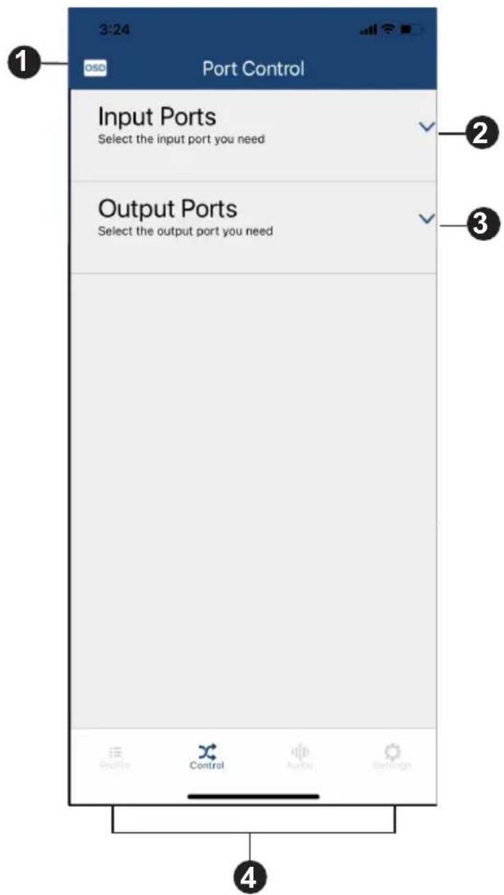
Control Tab
In the Control tab, you can instantly switch video inputs for each of the output.
text_image
3:24 OSD Port Control Input Ports Select the input port you need Output Ports Select the output port you need Profile Control Audio SettingsEach functions are described in the table below.
| No. | Component Description |
1 OSD Tap to enable or disable the OSD. | |
| 2 Input Ports Tap to select a video input port for the video output port. | |
| 3 Output Ports Tap to select a video output port for the video input port. | |
| 4 ConfigurationTab | Tap to make configuration to Profile, Control, Audio, and Settings tabs. |
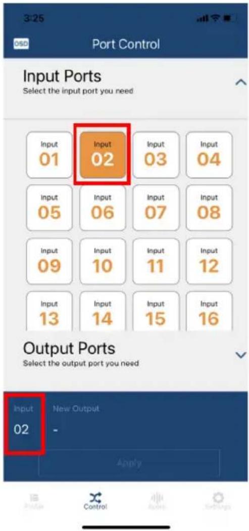
Switching the Video Inputs for the Video Output
To switch a video input for a designated video wall output ports, do the following:
- Tap Input Ports to select a video input. The selected video input port number will be shown in the apply section.
text_image
3:25 OSD Port Control Input Ports Select the input port you need Input 01 Input 02 Input 03 Input 04 Input 05 Input 06 Input 07 Input 08 Input 09 Input 10 Input 11 Input 12 Input 13 Input 14 Input 15 Input 16 Output Ports Select the output port you need Input New Output 02 - Apply- Select a video output or a video output group for the video input. The selected video output or video output group port number will be shown in the apply section, and then tap Apply.

text_image
3:25 OSD Port Control Input Ports Select the input port you need Output Ports Select the output port you need Output 01 Output 02 Output 03 Output 04 Output 05 Output 06 Output 07 Output 08 Output 09 Output 10 Output 11 Output 12 Output 13 Output 14 Output 15 Output 16 Input New Output 02 03,04,07,08, Apply- Now the video inputs and video outputs are switched.
text_image
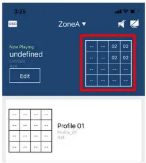
3:25 OSD ZoneA Now Playing undefined Untitled Edit -- -- 02 02 -- -- 02 02 -- -- -- -- -- -- -- -- -- -- -- -- Profile 01 Profile_01 4x6Audio Tab
In the Audio tab, you can specify the audio input for the digital and analog outputs of the Video Matrix Switch.
Note: The fields available in this tab may vary depending on the connected devices.
VM1600 / VM3200 / VM3250

text_image
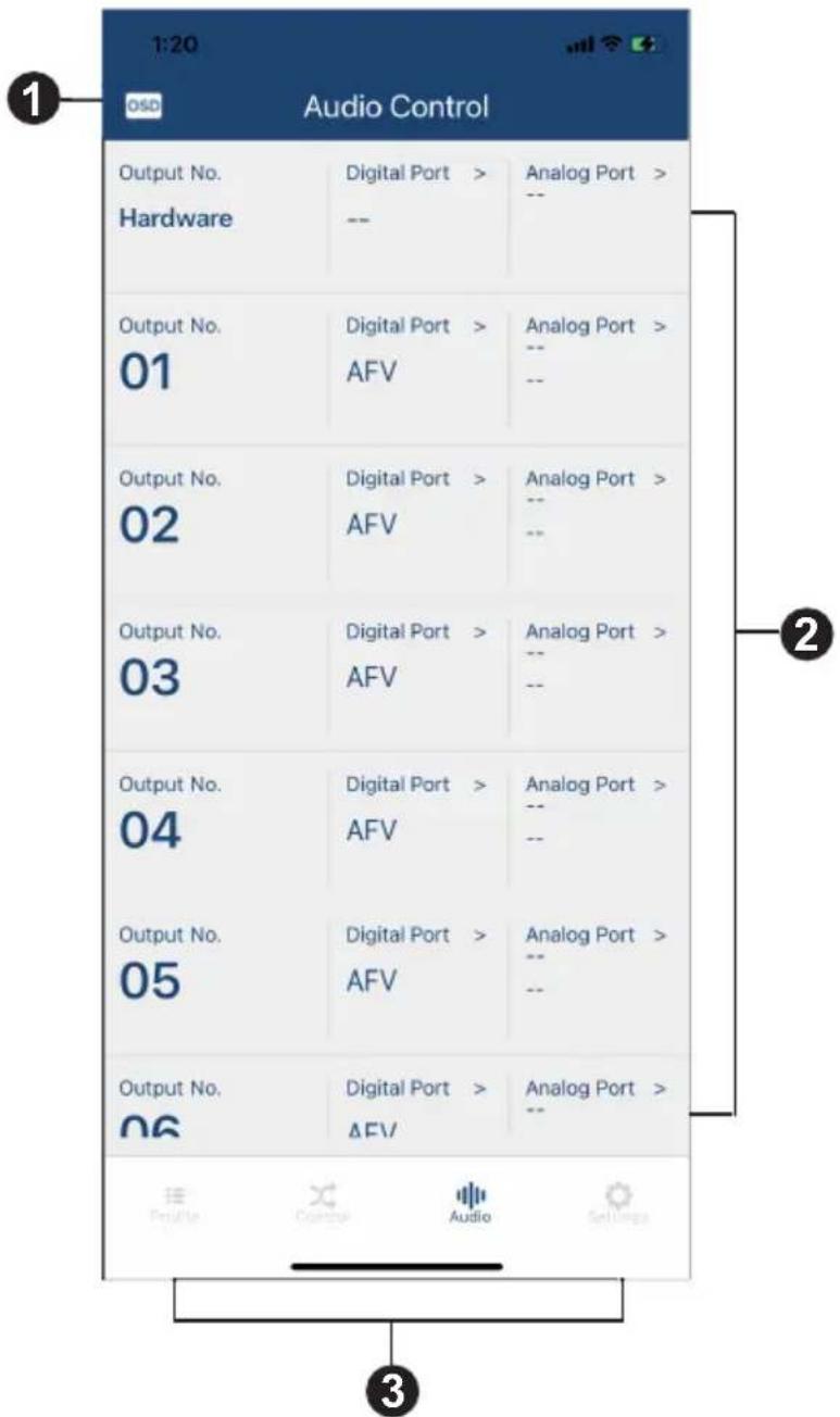
4:08 OSD Audio Control Output No. 01 Digital Port > Analog Port > Port_In_1 Mute Analog Output No. 02 Digital Port > Analog Port > Port_In_2 AFV Analog Output No. 03 Digital Port > Analog Port > Port_In_3 AFV Analog Output No. 04 Digital Port > Analog Port > Port_In_4 AFV Analog Output No. 05 Digital Port > Analog Port > Port_In_5 AFV Analog Output No. 06 Digital Port > Analog Port > Port_In_6 AFV Analog Output No. 07 Digital Port > Analog Port > Port_In_7 AFV Analog 3VM0404HB / VM0808HB / VM3404H-VM3909H / VM5404D / VM5404H / VM5808D / VM5808H / VM51616H / VM6404H / VM6404HB / VM6809H
text_image
1:20 OSD Audio Control Output No. Digital Port > Analog Port > Hardware -- -- Output No. Digital Port > Analog Port > 01 AFV -- -- Output No. Digital Port > Analog Port > 02 AFV -- -- Output No. Digital Port > Analog Port > 03 AFV -- -- Output No. Digital Port > Analog Port > 04 AFV -- -- Output No. Digital Port > Analog Port > 05 AFV -- -- Output No. Digital Port > Analog Port > 06 AFV -- Audio Control Audio Settings ① ② ③A warning message appears when you tap the Audio tab from the Video Matrix Control App.
Note: This warning message only appears on the Video Matrix Control App when the connected device is VM51616H / VM6404HB / VM6809H.
The controls are described in the table below.
| No. | Component Description |
1 OSD Tap to enable or disable the OSD. | |
| 2 Audio OutputPorts | Shows the available audio output ports and tap to specify the audio input for the digital and analog outputs for the Video Matrix Switch.Note: For VM51616H, VM6404HB, and VM6809H, the digital audio output ports can only be muted or set to follow the displayed video using the Audio Follow Video (AFV) setting. |
| 3 ConfigurationTab | Tap to make configuration to Profile, Control, Audio, and Settings tabs. |
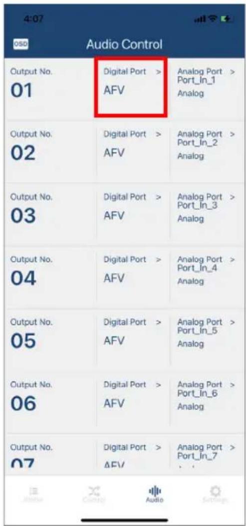
Specifying the Audio Inputs for the Digital and Analog Outputs
To specify an audio input for the digital and analog outputs, do the following:
- Tap the selected audio output port number's Digital Port.
text_image
4:07 050 Audio Control Output No. 01 Digital Port > AFV Analog Port > Port_In_1 Analog Output No. 02 Digital Port > AFV Analog Port > Port_In_2 Analog Output No. 03 Digital Port > AFV Analog Port > Port_In_3 Analog Output No. 04 Digital Port > AFV Analog Port > Port_In_4 Analog Output No. 05 Digital Port > AFV Analog Port > Port_In_5 Analog Output No. 06 Digital Port > AFV Analog Port > Port_In_6 Analog Output No. 07 Digital Port > AFV Analog Port > Port_In_7 Audio- Select an option for digital port, then tap Select.

text_image
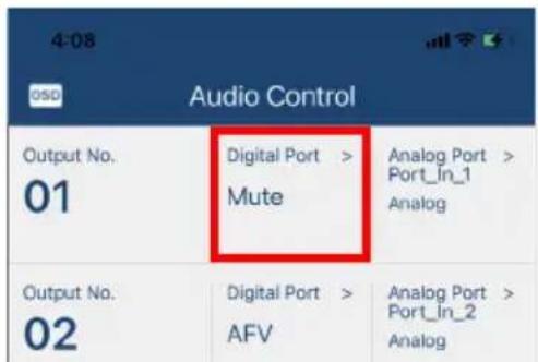
4:08 OSD Audio Control Output No. 01 Digital Port > Analog Port > AFV Port_In_1 Analog Output No. 02 Digital Port > Analog Port > AFV Port_In_2 Analog Output No. 03 Digital Port > Analog Port > AFV Port_In_3 Analog Output No. 04 Digital Port > Analog Port > AFV Port_In_4 Analog Output No. 05 Digital Port > Analog Port > AFV Port_In_5 Analog Digital Port Select AFV Mute Analog- Now the digital output is muted.
text_image
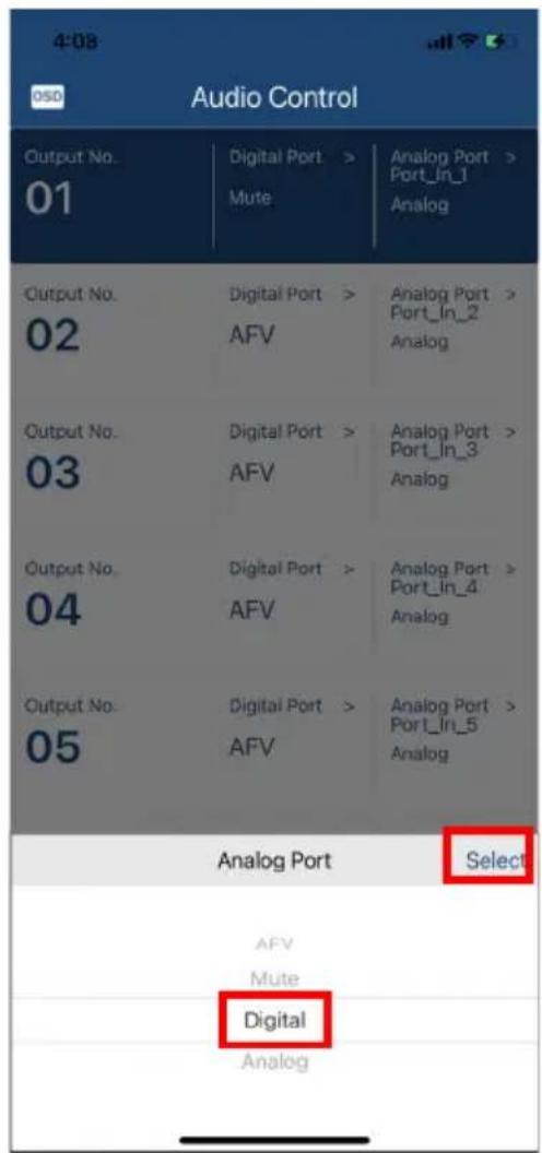
4:08 Audio Control Output No. 01 Digital Port > Mute Analog Port > Port_In_1 Analog Output No. 02 Digital Port > AFV Analog Port > Port_In_2 Analog4. Select an option for the analog port.
text_image
4:08 OSO Audio Control Output No. 01 Digital Port > Analog Port > Mute Port_In_1 Analog Output No. 02 Digital Port > Analog Port > AFV Port_In_2 Analog Output No. 03 Digital Port > Analog Port > AFV Port_In_3 Analog Output No. 04 Digital Port > Analog Port > AFV Port_In_4 Analog Output No. 05 Digital Port > Analog Port > AFV Port_In_5 Analog Analog Port Select AFV Mute Digital Analog
text_image
4:08 050 Audio Control Output No. 01 Digital Port > Analog Port > Mute Port_In_1 Analog Output No. 02 Digital Port > Analog Port > AFV Port_In_2 Analog Output No. 03 Digital Port > Analog Port > AFV Port_In_3 Analog Output No. 04 Digital Port > Analog Port > AFV Port_In_4 Analog Output No. 05 Digital Port > Analog Port > AFV Port_In_5 Analog Back Analog Port Save 1:Port_In_1 2:Port_In_2 3:Port_In_3 4:Port_In_45. Now the audio input is specified to the digital and analog outputs.

text_image
4:08 OSD Audio Control Output No. 01 Digital Port > Analog Port > Port_In_2 Mute Digital Output No. 02 Digital Port > Analog Port > Port_In_2 AFV Analog Output No. 03 Digital Port > Analog Port > Port_In_3 AFV Analog Output No. - - - - - - - - - - - - - - - - - - - - - - - - - - - - - - - - - - - - - - - - - - - - - - - - - - - - - - -Settings Tab
In the Settings tab, you can look up notification for system firmware updates, the current app version, and technical support contact, or log out of the app.

text_image
4:46 Settings SYSTEM SETTINGS VM Firmware Versions > ABOUT Version 1.1.102 Contact Us Log Out ATEN Copyright (c) 2020© Copyright 2021 ATEN® International Co., Ltd.
Released: 2022-01-10
ATEN and the ATEN logo are registered trademarks of ATEN International Co., Ltd. All rights reserved. All other brand names and trademarks are the registered property of their respective owners.