40-BAY-SLIM - NAS Remii - Free user manual and instructions
Find the device manual for free 40-BAY-SLIM Remii in PDF.

User questions about 40-BAY-SLIM Remii
0 question about this device. Answer the ones you know or ask your own.
Ask a new question about this device
Download the instructions for your NAS in PDF format for free! Find your manual 40-BAY-SLIM - Remii and take your electronic device back in hand. On this page are published all the documents necessary for the use of your device. 40-BAY-SLIM by Remii.
USER MANUAL 40-BAY-SLIM Remii
Remi Electric Fireplaces
INSTALLATION AND OPERATION INSTRUCTIONS
30-BAY SLIM
40-BAY SLIM
50-BAY SLIM
60-BAY SLIM
72-BAY SLIM
natural_image
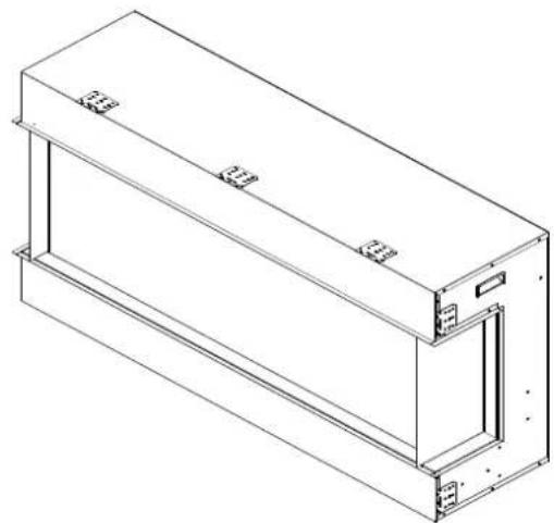
Technical line drawing of a rectangular mechanical housing or enclosure with mounting brackets and internal compartments (no text or symbols)SAFETY INFORMATION

WARNING
If the information in these instructions are not followed exactly, a fire or explosion may result causing property damage, personal injury or loss of life.
Do not store or use gasoline or other flammable vapors and liquids in the vicinity of this or any other appliance.
INSTALLER: LEAVE THIS MANUAL WITH THE APPLIANCE. CONSUMER: RETAIN THIS MANUAL FOR FUTURE REFERENCE.
TABLEeOFeCONTENTSe
Please read and carefully follow all instructions found in this manual. The instructions included here will assure that you have many years of dependable and enjoyable service from your Remii electric fireplace.
IMPORTANT INSTRUCTIONS....3
UNPACKING AND TESTING APPLIANCE 4
GROUNDING APPLIANCE 4
LOCATING THE FIREPLACE....4
30-BAY SLIM 5
40-BAY SLIM 6
50-BAY SLIM 7
60-BAY SLIM 8
72-BAY SLIM 9
SAFETY DRILL SCREW AREA 10
HARD-WIRE INSTALLATION....10
FOR BATHROOM USE 11
OUTDOOR INSTALLATIONS 12
INSTALLATION....13
MEDIA OPTIONS....19
OPERATION....20
INSTALLING WALL THERMOSTAT 22
REPLACEMENT PARTS....23
EXPLODED VIEW 25
WIRING DIAGRAM 26
TROUBLE SHOOTING....27
SERVICE HISTORY....28
WARRANTY 29
IMPORTANTeINSTRUCTIONSe
PLEASE RETAIN THIS USER GUIDE FOR FUTURE REFERENCE
When using electrical appliances, basic precautions should always be followed to reduce the risk of fire, electric shock, and injury to persons, including the following:
1) Read all instructions before using this fireplace
2) The fireplace is hot when in use. To avoid burns, do not let bare skin touch hot surfaces. Keep combustible material such as furniture, cushions, bedding, paper, clothes, curtains at least 3 feet from the front of the unit
3) Extreme caution is necessary when any heater is used near children and whenever the unit is left operating and unattended
4) Do not operate a fireplace with a damaged cord or plug, or if the heater has malfunctioned, the fireplace has dropped or damaged in any manner
5) Not all fireplaces are suitable for use in bathrooms or laundry facilities. Please consult with individual product literature to confirm suitability
6) Do not run the cord under carpeting. Do not cover cord with throw rugs, runners or the like. Arrange the cord away from traffic area and where it will not be tripped over
7) Do not modify this fireplace. Use it as described in the manual. Any other use not recommended by the manufacture may cause fire, shock or injury to persons
8) Do not use this heater with a programmer, timer, separate remote-control system or any other device that switches the heater on automatically, since a fire risk exists if the heater is covered or positioned incorrectly
9) Disconnect all power supply before cleaning, maintenance or relocation of the fireplace
10) Keep the heater clean. Do not allow any objects to enter any ventilation or exhaust opening as this may cause electric shock, fire or damage to the heater
11) Do not immerse the cord, plug or any part of the appliance in water or any other liquid
12) In order to avoid a hazard due to inadvertent resetting of the thermal cut-out, this appliance must not be supplied through an external switching device
CAUTION: Procedures and techniques, which, if not carefully followed, will result in damage to the equipment.
WARNING: Procedures and techniques, which, if not carefully followed, will expose the user to the risk of fire, serious injury, illness or death.
UNPACKING AND TESTING APPLIANCE
Carefully remove the appliance from the box.
Prior to installing the appliance, test to make sure the appliance operates properly by plugging the power supply cord into a conveniently located 120 Volt grounded outlet.
Test all aspects of its operation (manual switches, remote and heater) to make sure all components operate correctly.
As with most electronic devices, your new electric fireplace has been designed to operate at temperatures between 5 °C (41°F) and 35 °C (95°F). During the cold winter months, allow the fireplace to reach room temperature before turning it on.
NOTE: There may be trace of odor during the first few minutes of initial use. This is harmless, normal and will never occur again.
GROUNDING APPLIANCE
This appliance is for use on 120 Volts. The cord has a plug as shown in (A). An adapter as shown in (C) is available for connecting three-blade grounding type plugs to two-slot receptacles. The green grounding lug extending from the adapter must be connected to a permanent ground such as a properly grounded outlet box. The adapter should not be used if a three-slot grounded receptacle is available.
To disconnect appliance, turn controls to off, then remove plug from outlet.
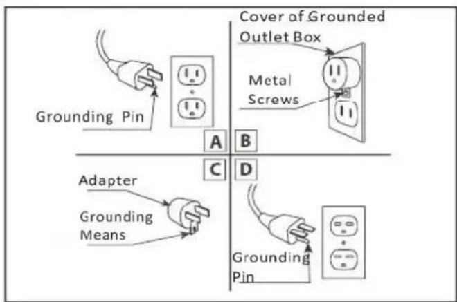
text_image
Grounding Pin Cover of Grounded Outlet Box Metal Screws A B C D Adapter Grounding Means Grounding PinLOCATING THE FIREPLACE
Plan where to locate and frame the fireplace. This will save time and money later when you install the fireplace. Before installation consider the following:
- Where the fireplace is located must allow for wall and ceiling clearances
- Consider a location where the fireplace screen will not be exposed to direct sunlight from windows or doors.
- A 15 ampere, 120 Volt, 60 Hz branch circuit with proper ground must be available at the location. Preferably a dedicated branch circuit should be provided to avoid circuit breakers to trip of fuses to blow.
30- BAY SLIM
| Description | Built-in Appliance |
| Voltage | 120V AC 60Hz |
| Watts | 1465W Max |
| NO HEATER | 25W |
| MOTOR HEATER | 19W |
| Appliance Width | 33 1/4" or 84.4 cm |
| Appliance Height | 26 5/8" or 67.7 cm |
| Appliance Depth | 10 5/8" or 27 cm |
| Gross Weight | 85.3 lbs or 38.7 kgs |
| Plug Location | Left side |
| Cord Length | 70 7/8" or 180 cm |
| Rough Wall Opening Size | 33 3/4" × 27 5/8" or 85.7 cm × 70.2 cm |
| BTU 5000 |
This appliance has been tested in accordance with the UL Standard 2021 for fixed and location dedicated electric room appliances in the United States and Canada. If you need assistance during installation, please contact your local dealer.
NOTE: This appliance must be electrically wired and grounded in accordance with local codes. In the absence of local codes, use the current CSA C22.1 Canadian Electrical Code in Canada or the ANSI/NFPA 70 National Electrical Code in the United States.
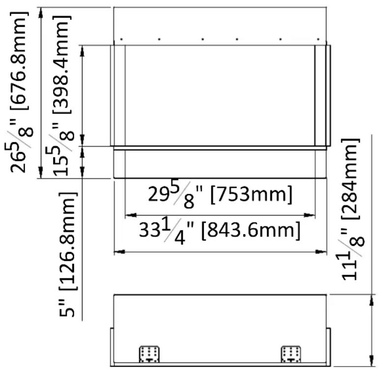
text_image
265/8" [676.8mm] 155/8" [398.4mm] 5" [126.8mm] 295/8" [753mm] 331/4" [843.6mm] 111/8" [284mm]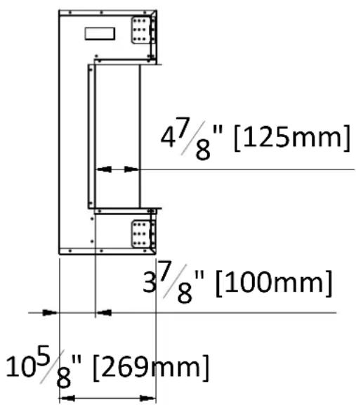
text_image
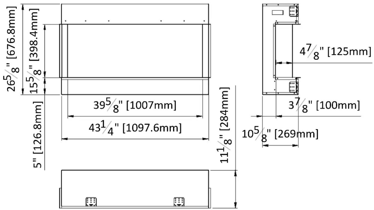
47/8" [125mm] 37/8" [100mm] 105/8" [269mm]40-BAY SLIM
| Description | Built-in Appliance |
| Voltage | 120V AC 60Hz |
| Watts | 1465W Max |
| NO HEATER | 25W |
| MOTOR HEATER | 19W |
| Appliance Width | 43 1/4" or 109.7 cm |
| Appliance Height | 26 5/8" or 67.7 cm |
| Appliance Depth | 10 5/8" or 36.3 cm |
| Gross Weight | 103.6 lbs or 47 kgs |
| Plug Location | Left side |
| Cord Length | 70 7/8" or 180 cm |
| Rough Wall Opening Size | 43 3/4" × 27 5/8" or 111.2 cm × 70.2 cm |
| BTU 5000 |
This appliance has been tested in accordance with the UL Standard 2021 for fixed and location dedicated electric room appliances in the United States and Canada. If you need assistance during installation, please contact your local dealer.
NOTE: This appliance must be electrically wired and grounded in accordance with local codes. In the absence of local codes, use the current CSA C22.1 Canadian Electrical Code in Canada or the ANSI/NFPA 70 National Electrical Code in the United States.
text_image
265/8" [676.8mm] 155/8" [398.4mm] 5" [126.8mm] 395/8" [1007mm] 431/4" [1097.6mm] 111/8" [284mm] 47/8" [125mm] 37/8" [100mm] 105/8" [269mm]50-BAY SLIM
| Description | Built-in Appliance |
| Voltage | 120V AC 60Hz |
| Watts | 1465W Max |
| NO HEATER | 25W |
| MOTOR HEATER | 19W |
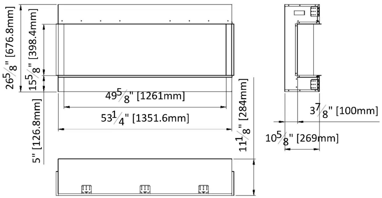
| Appliance Width | 53 1/4" or 135.2 cm |
| Appliance Height | 26 5/8" or 67.7 cm |
| Appliance Depth | 10 5/8" or 27 cm |
| Gross Weight | 121.5 lbs or 55.1 kgs |
| Plug Location | Left side |
| Cord Length | 70 7/8" or 180 cm |
| Rough Wall Opening Size | 53 3/4" × 27 5/8" or 136.5 cm × 70.2 cm |
| BTU 5000 |
This appliance has been tested in accordance with the UL Standard 2021 for fixed and location dedicated electric room appliances in the United States and Canada. If you need assistance during installation, please contact your local dealer.
NOTE: This appliance must be electrically wired and grounded in accordance with local codes. In the absence of local codes, use the current CSA C22.1 Canadian Electrical Code in Canada or the ANSI/NFPA 70 National Electrical Code in the United States.
text_image
265/8" [676.8mm] 155/8" [398.4mm] 5" [126.8mm] 495/8" [1261mm] 531/4" [1351.6mm] 111/8" [284mm] 37/8" [100mm] 105/8" [269mm]60-BAY SLIM
| Description | Built-in Appliance |
| Voltage | 120V AC 60Hz |
| Watts | 1465W Max |
| NO HEATER | 25W |
| MOTOR HEATER | 19W |
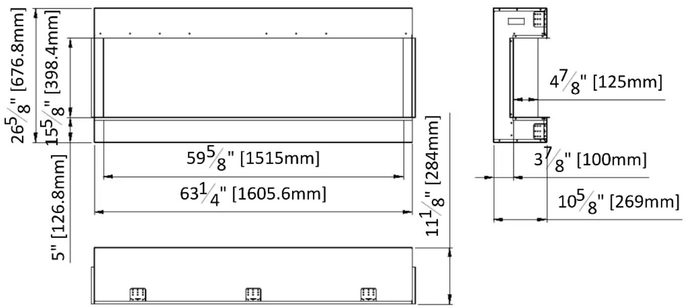
| Appliance Width | 63 1/4" or 160.6 cm |
| Appliance Height | 26 5/8" or 67.7 cm |
| Appliance Depth | 10 5/8" or 27cm |
| Gross Weight | 140.2 lbs or 63.6 kgs |
| Plug Location | Left side |
| Cord Length | 70 7/8" or 180 cm |
| Rough Wall Opening Size | 63 3/4" × 27 5/8" or 162 cm × 70.2 cm |
| BTU 5000 |
This appliance has been tested in accordance with the UL Standard 2021 for fixed and location dedicated electric room appliances in the United States and Canada. If you need assistance during installation, please contact your local dealer.
NOTE: This appliance must be electrically wired and grounded in accordance with local codes. In the absence of local codes, use the current CSA C22.1 Canadian Electrical Code in Canada or the ANSI/NFPA 70 National Electrical Code in the United States.
text_image
265/8" [676.8mm] 155/8" [398.4mm] 5" [126.8mm] 595/8" [1515mm] 631/4" [1605.6mm] 111/8" [284mm] 47/8" [125mm] 37/8" [100mm] 105/8" [269mm]72-BAY SLIM
| Description | Built-in Appliance |
| Voltage | 120V AC 60Hz |
| Watts | 1465W Max |
| NO HEATER | 25W |
| MOTOR HEATER | 19W |
| Appliance Width | 75 1/4" or 191 cm |
| Appliance Height | 26 5/8" or 67.7 cm |
| Appliance Depth | 10 5/8" or 27 cm |
| Gross Weight | 167.1 lbs or 75.8 kgs |
| Plug Location | Left side |
| Cord Length | 70 7/8" or 180 cm |
| Rough Wall Opening Size | 75 3/4" × 27 5/8" or 192.4 cm × 70.2 cm |
| BTU 5000 |
This appliance has been tested in accordance with the UL Standard 2021 for fixed and location dedicated electric room appliances in the United States and Canada. If you need assistance during installation, please contact your local dealer.
NOTE: This appliance must be electrically wired and grounded in accordance with local codes. In the absence of local codes, use the current CSA C22.1 Canadian Electrical Code in Canada or the ANSI/NFPA 70 National Electrical Code in the United States.

text_image
265/8" [676.8mm] 155/8" [398.4mm] 5" [126.8mm] 715/8" [1819.8mm] 751/4" [1910.4mm] 111/8" [284mm] 47/8" [125mm] 37/8" [100mm] 105/8" [269mm]SAFETY DRILL SCREW AREA
There is a safety drill screw area as show below.
Please make sure that the fix screws are in this area.

The manual control pad position
Safety drill screw area (Dark area)
HARD- WIRE INSTALLATION
Turn off the appliance completely and let cool before servicing. Only a qualified service person should service and repair this electric appliance.
If it is necessary to hard wire this appliance, a qualified electrician must remove the cord connection, and wire the appliance directly to the household wiring.
This appliance must be electrically connected and grounded in accordance with local codes, if hard wired. In the absence of local codes, use the current CSA C22.1 CANADIAN ELECTRICAL CODE in Canada or the current ANSI/NFPA 70 NATIONAL ELECTRICAL CODE in the United States.
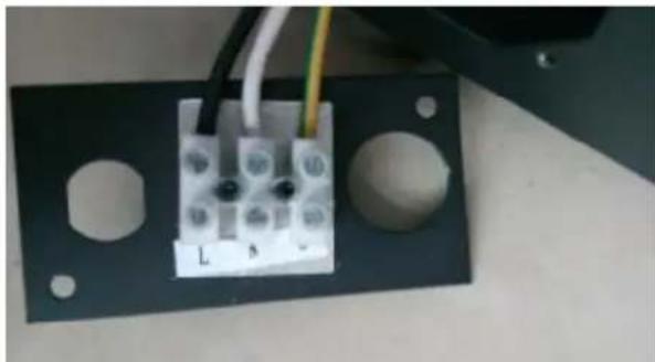
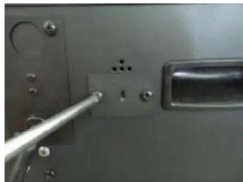
- Remove the cover plate from the left side of the appliance by removing the two screws, as shown below. Unscrew and remove power cord.
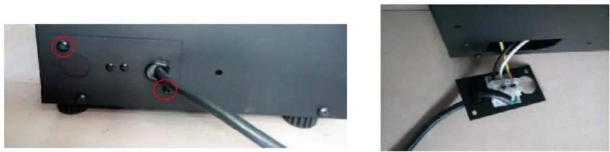
- Attach the wiring to the junction block. Please make sure the live wire goes into the "L", the neutral wire into "N" and the ground wire into "G".
natural_image
Close-up of a black metal bracket with two circular holes and three white terminal blocks, connected by wires (no visible text or symbols)
natural_image
Close-up of a black electronic device with a blue and yellow cable inserted into a socket (no visible text or symbols)- Put the plate back and screw back.
FOR BATHROOM USE
If this unit is installed in a bathroom it must be protected by a GIF receptacle or circuit. If receptacle is used it must be readily accessible.
To prevent electric shock, please be aware that this unit is an electrical appliance that is NOT watertight and must be installed as to prevent water from entering unit. This must be installed away from shows, tubs, etc. Never locate fireplace where it may fall into a bathtub or other water container.
All wiring connections to line power shall be in accordance with local building code requirements. Inquires about local codes and regulations must be done prior to installation.
The BAY SLIM series of electric fireplaces are suitable for installation in outdoor areas protected from direct water impingement. In addition to maintaining the listed mantel and combustibles clearances, a rain protection overhang factor of 1/2 shall be constructed to the front and to each side of the installed appliance. See illustration below. All wiring connections to line power shall be in accordance with local building code requirement. Inquires about local codes and regulations must be done prior to installation.

text_image
Side of Fireplace A BThe overhang (A) must extend at least 1/2 the roof-line height (B). Height is measured from the base of the fireplace.
For example: if the roof-line (B) is 8' above the base of the fireplace, the overhang (A) must be at least 4'.
INSTALLATION
The BAY SLIM models are designed to be built in and allow for the finishing material(dry wall, stone, tile, etc) to be built right down to the glass edge. The rough wall opening size of the fireplace:
Note: Due to the many different materials used on walls, it is highly recommended that you consult your local builder before you install this appliance.
| W( " ) | D( " ) | H( " ) | |
| 30-BAYSLIM | 33 3/4 | 11 1/8" | 27 1/8 |
| 40-BAYSLIM | 43 3/4 | 11 1/8" | 27 1/8 |
| 50-BAYSLIM | 53 3/4 | 11 1/8" | 27 1/8 |
| 60-BAYSLIM | 63 3/4 | 11 1/8" | 27 1/8 |
| 72-BAYSLIM | 75 3/4 | 11 1/8" | 27 1/8 |

natural_image
Isometric line drawing of a multi-story building facade with vertical supports and horizontal beams, labeled with dimensions H and D (no text or symbols beyond basic geometry)- Product is fixed with fending bars panels on the left and right side.
natural_image
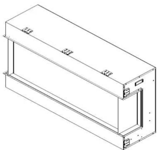
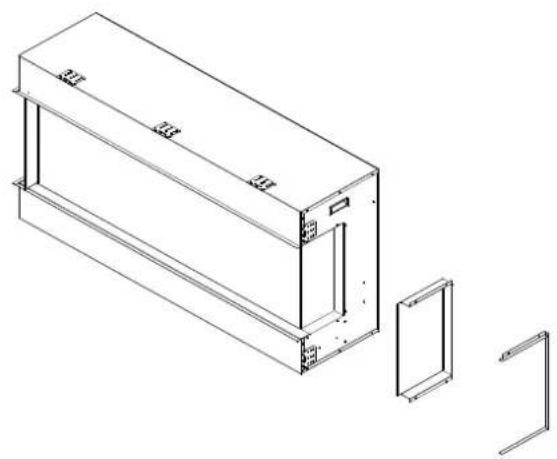
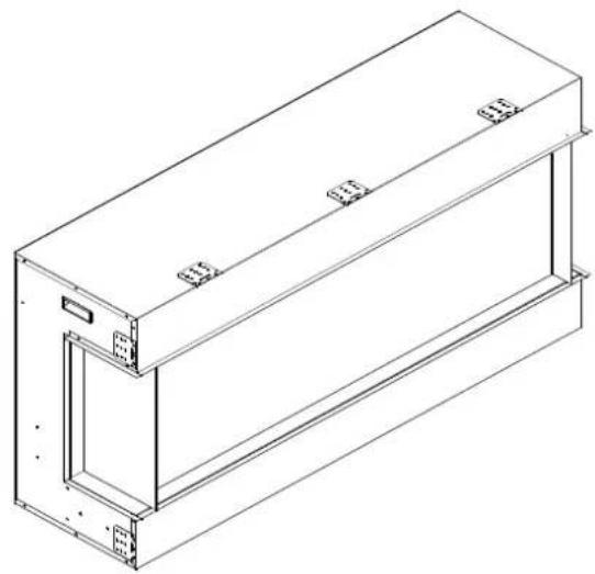
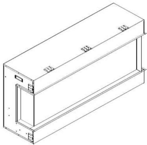
Technical line drawing of a rectangular mechanical or electrical enclosure with mounting holes and internal compartments (no text or symbols)- Take off the fending bars and panels if you want to view the fire from three angles.

text_image
fending panel fending bar- Screw back the fending bar after the panel is removed.

natural_image
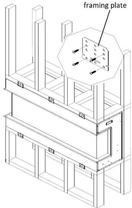
Technical line drawing of a rectangular mechanical or architectural component with mounting holes and internal channels (no text or symbols)- Remove the framing plates from the fireplace and fix them as the picture shows. NOTE: After removing framing plates on the left and right sides, screw back the screws.

text_image
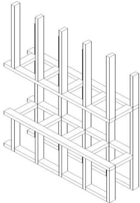
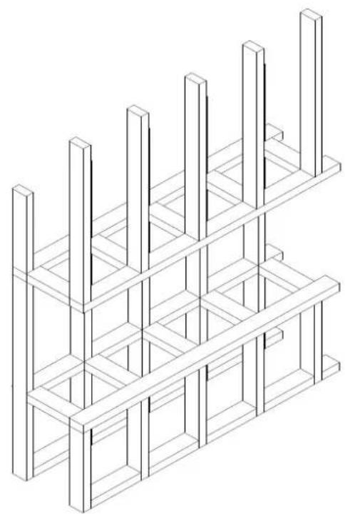
framing plate- Make an opening for the fireplace according to requested measurement.
natural_image
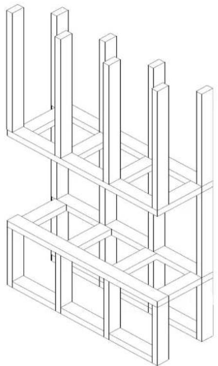
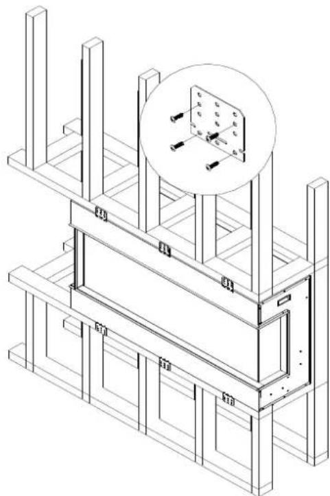
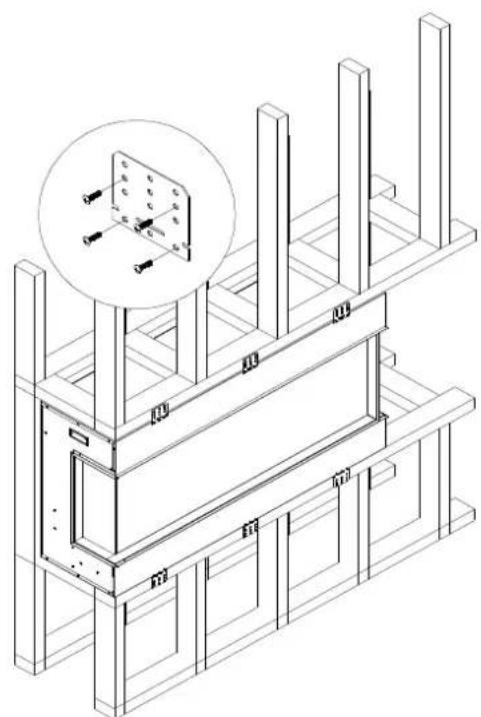
Isometric line drawing of a multi-level structure with vertical supports and horizontal beams (no text or symbols)- Insert the fireplace into the wall opening. Drive the mounting screws into the frame plates on the unit and the wall studs. To fix the bottom of the fireplace and the wall studs with the framing plates that you've removed from left and right side of the fireplace at STEP 4. Plug in and check if the fireplace works.
text_image
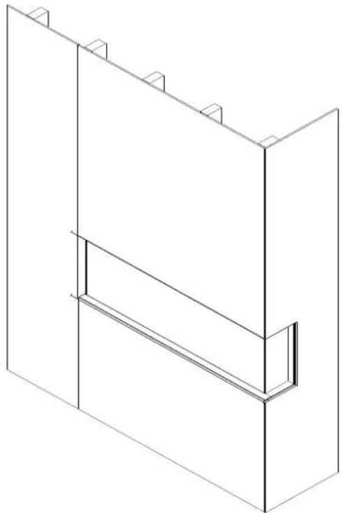
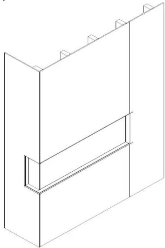
framing plate- After checking that the fireplace operates properly, cover the glass panels with protective plastic bag and install plywood or drywall.
natural_image
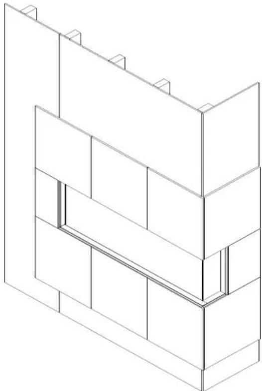
Isometric line drawing of a two-tiered structural frame or panel (no text or symbols)- Decorate the plywood or drywall with glazed tile, wallpaper, etc.
natural_image
Isometric line drawing of a multi-story building facade with no text or symbolsInstallation for Front and right side Viewing
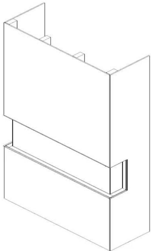
- To install the fireplace where the left side is close to a wall, and you want to view the fire from front and right side, take off the fending panel on the right.

natural_image
Technical line drawing of a rectangular mechanical or architectural component with mounting holes and internal channels (no text or symbols)- Unscrew 7screws on the right side that fix the fending bar and panel and then take off the fending bar and panel.
natural_image
Technical line drawing of a rectangular enclosure with internal frame and two separate views (no text or symbols)- After the fending panel is removed, screw back the bar.

natural_image
Isometric line drawing of a rectangular mechanical or electrical enclosure with mounting holes and internal components (no text or symbols)- Remove the framing plates from the fireplace and fix them as the picture shows. NOTE: After removing framing plates on the left and right sides, screw back the screws.

natural_image
Technical line drawing of a rectangular industrial or structural component with mounting holes and internal channels (no text or symbols)- Make an opening for the fireplace according to requested measurement.
natural_image
Isometric line drawing of a multi-level structure with vertical supports and horizontal beams (no text or symbols)- Insert the fireplace into the wall opening. Drive the mounting screws into the frame plates on the unit and the wall studs. To fix the bottom of the fireplace and the wall studs with the framing plates that you've removed from left and right side of the fireplace at STEP 4. Plug in and check if the fireplace works.
natural_image
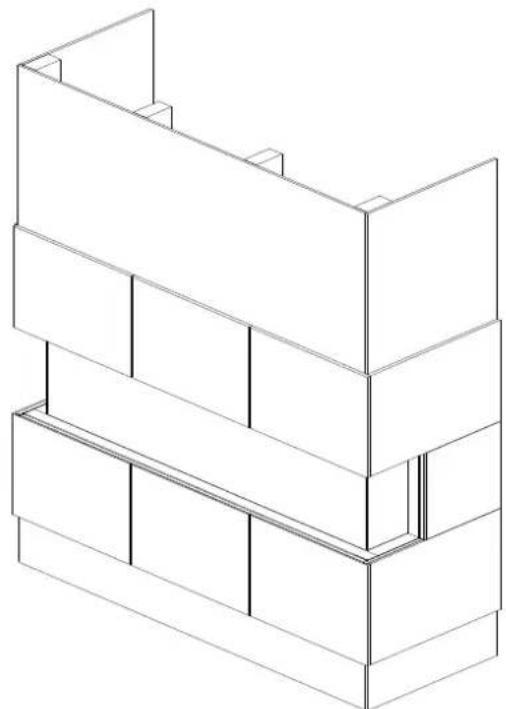
Isometric technical drawing of a structural frame with supports and a magnified inset showing a small component (no text or symbols)- After checking that the fireplace operates properly, cover the glass panels with protective plastic bag and install plywood or drywall.
natural_image
Isometric line drawing of a two-story building facade with vertical supports and horizontal beams (no text or symbols)- Decorate the plywood or drywall with glazed tile, wallpaper, etc.
natural_image
Isometric line drawing of a multi-story building facade with vertical supports and horizontal beams (no text or symbols)Installation for Front and Left Side Viewing
- Install the fireplace where the right side is close to a wall, and you want to view the fire from front and left side, take off the fending panel on the left.
natural_image
Technical line drawing of a rectangular enclosure or enclosure with mounting holes and internal compartments (no text or symbols)- Unscrew 7 screws on the left side that fix the fending bar and panel and then take off the fending bar and panel.

natural_image
Technical line drawing of a rectangular enclosure with internal doors and mounting brackets (no text or symbols)- After the fending panel is removed, screw back the bar.
natural_image
Technical line drawing of a rectangular electronic enclosure or enclosure with mounting brackets and internal compartments (no text or symbols)- Remove the framing plates from the fireplace and fix them as the picture shows. NOTE: After removing the framing plates on the left and right sides, screw back the screws.

natural_image
Technical line drawing of a rectangular structural component with mounting holes and dimension lines (no text or symbols)- Make an opening for the fireplace according to requested measurement.
natural_image
Isometric line drawing of a multi-level structure with vertical supports and horizontal beams (no text or symbols)-
Insert the fireplace into the wall opening. Drive the mounting screws into the frame plates on the unit and the wall studs. To fix the bottom of the fireplace and the wall studs with the framing plates that you've removed from left and right side of the fireplace at STEP 4. Plug in and check if the fireplace works.
-
After checking that the fireplace operates properly, cover the glass panels with protective plastic bag and install plywood or drywall.
natural_image
Isometric line drawing of a structural frame or panel with vertical supports and a central rectangular block (no text or symbols)- Decorate the plywood or drywall with glazed tile, wallpaper, etc.
natural_image
Isometric technical drawing of a structural frame with supports and a magnified inset showing a small component (no text or symbols)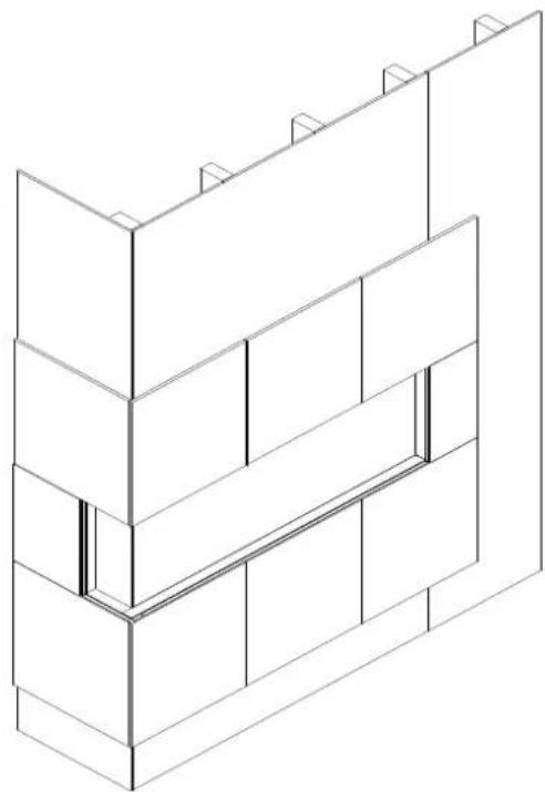
natural_image
Isometric line drawing of a brick wall structure with no text or symbolsMEDIA OPTIONS -The Bay Slim series models are shipped with a 10 piece birch media kit

natural_image
Collection of dried plant roots and soil samples arranged in rows (no text or labels visible)DESIGN-MEDIA-BIRCH-10PCE
MEDIA OPERATION
- Unscrew 2 screws and take off two brackets which are fending the front glass panel.
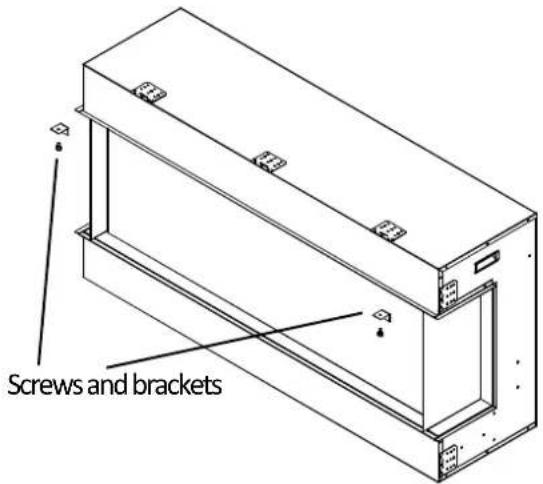
text_image
Screws and brackets- After the brackets are removed, the front glass panel will fall down automatically.

natural_image
Technical line drawing of a mechanical assembly with no visible text or symbols- Take off the front glass panel and put it in safe place.

natural_image
Technical line drawing of a structural frame assembly (no text or symbols)-
Installing the fire glass media. Pour the fire glass media into the tray as shown below. Feel free to use any combination of fire glass media that you find most appealing.
-
Put back the front glass and screw back the bracket.
OPERATION
The fireplace can be operated either by the switches located on the left bottom of the fireplace unit or by supplied remote control.
Plug the fireplace into a 15 Amp wall socket.
MANUAL OPERATION

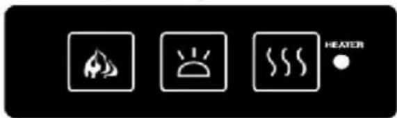
text_image
HEATER- The main power ON/OFF switch in position O, the fireplace is OFF.
- When main power ON/OFF switch is at position I, the fireplace is ready to use.
- Press the 🎨 button repeatedly to set the heater to desired heat setting. The heater indicator LED will glow which shows the current heater settings.
a) RED 1465W HEAT OUTPUT
b) BLUE 750W HEAT OUTPUT
c) PURPLE AUTO MODE
AUTO MODE
Under this mode the heater will automatically turn ON at high heat setting 1465W heat output when the room temperature drops below 22^(72^) . When the room temperature is between 22-25^(72-77^) the heater output will switch to low heat setting 750W. When the room temperature goes above 25^(77^) the heater will be turned off and the cycle will continue. The LED indicator will be PURPLE in colour under this mode.
- Flame effect: Press the button marked 🔍 to adjust the flame brightness. The flame brightness will cycle through -Low-Medium-High -OFF.
- Mood light effect: Press the button marked ⚙ to change the mood light colour.
NOTE: If operated at the Low heat setting, the fireplace will not provide as much heat output as in the High heat setting, however the low setting will not require as much electrical power to operate. To avoid overloading a circuit, do not plug the fireplace into a circuit that already has other appliances working. When the fireplace is not in use switch off and unplug.
SAFETY CUT-OFF
This appliance is fitted with a safety cut-off which will operate if the fireplace overheats (eg. Due to blocked air vents). For safety reasons, the fireplace will NOT automatically reset.
To reset the appliance, disconnect the appliance from the main supply for at least 10 minutes. Reconnect the main power supply and put the main power switch to the ON position.
natural_image
Line drawings of a remote control unit, battery pack, and remote device (no text or symbols)For remote to function make sure the heater is plugged in and main power switch located on the bottom left hand side is at position I.
When operating the remote make sure you point the remote to the centre of the fireplace and make sure each time you press the button. The buzzer inside the unit will beep once. It takes some time for the receiver to respond to the transmitter. Do not PRESS the buttons more than once within two seconds for correct operation.
Power on ⏻ button: The power-on button at top left corner of the remote is the main ON/OFF power button. This will turn off all the functions and the fireplace will be in standby mode.
DISPLAY ON/OFF button: Switching the fireplace flame and tray light ON/OFF. It has functions of setting memory.
DISPLAY BLUE button: Adjust the blue color brightness of flame and tray.
DISPLAY YELLOW button: Adjust the yellow color brightness of flame and tray.
DISPLAY ORANGE button: Adjust the orange color brightness of flame and tray.
MOOD LIGHT ON/OFF button: Switching the mood light ON/OFF.
ADJUST button: Switching the color of the mood light.
FLASH button: Switches mood light into flash mode, this cycles through all mood light colors.
HEATER ON/OFF button: Switching the heater ON/OFF. It has functions of setting memory.
HIGHT button: Press the high button to switch the heater to high heat setting 1465W.
LOW button: Press the low button to switch the heater to low heat setting 750W.
TEMP. button: Press the TEMP. button to switch the heater to AUTO mode. Under this mode the heater will operate in similar way as explained above for the manual operation.
INSTALLING WALL THERMOSTAT
WALL THERMOSTAT WIRING DIAGRAMS
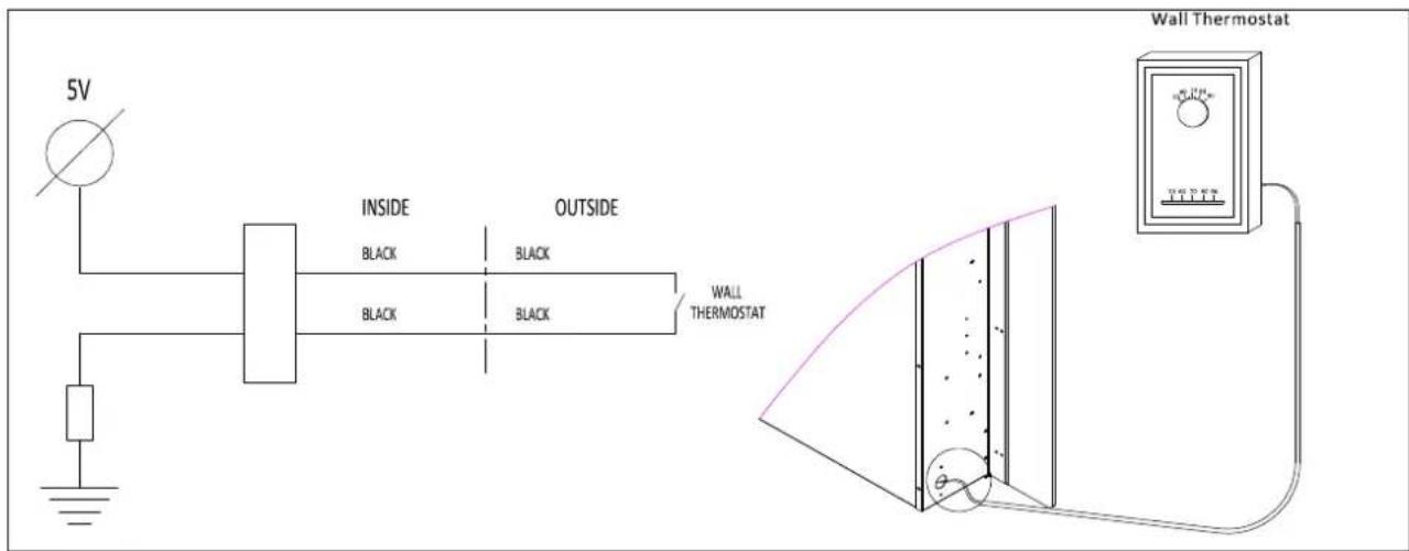
text_image
5V INSIDE OUTSIDE BLACK BLACK BLACK WALL THERMOSTAT Wall ThermostatWire the wall thermostat prior to installing the fireplace.
WALL THERMOSTAT WIRING(24 VAC)
Install Wall Thermostat per instructions provided with kit and per the following information:
- Turn off circuit breaker.
- Remove cover plate located on the left side of appliance.
- Pull the wire out and cut the inside thermostat. Connect the wires to the wall thermostat as shown below. Follow instructions provided with wall switch kit.
natural_image
Close-up of a metallic tool inserted into a mechanical component, showing bolt holes and a handle (no text or symbols visible)
natural_image
Close-up of a hand inserting a small metallic component into a dark circular socket (no text or symbols visible)
natural_image
Close-up of a hand using a power tool to press or install a small white cable into a black electronic device (no visible text or symbols)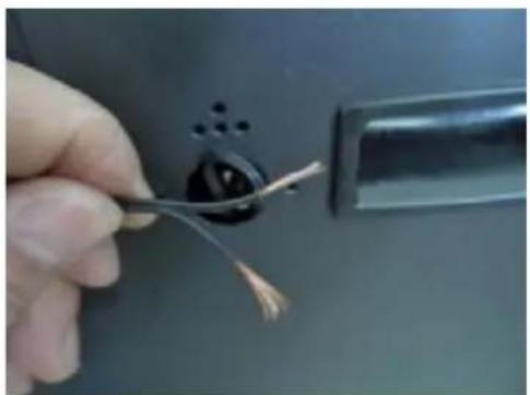
natural_image
Close-up of a hand holding a wire cable inserted into a black electrical socket (no text or symbols visible)REPLACEMENT PARTS
This list contains replacement parts
| NO | PART NUMBER | DESCRIPTION QTY | |||
| 30-BAY SLIM 40-BAY | SLIM 50-BAY SLIM | ||||
| 1 10 | 701384 10701281 107012 | 16 Front Clear Glass 1 | |||
| 2 10 | 201505 ADJUSTABLE SCREW 2 | ||||
| 3 31 | 23010 | FRONT CLEAR GLASS BRACKET | 2 | ||
| 4 10 | 702266 10702267 107022 | 68 BOTTOM TRAY GLASS 1 | |||
| 5 | 10702271 | 10701284B | 10701219B | BACK GLASS | 1 |
| 6 10 | 701385 SIDE CLEAR GLASS 2 | ||||
| 7 | 601136B | 601136B | 601136B | LED STRIP FOR TRAY AND FLAME | |
| 601141B | 601141B | 601141B | |||
| 8 | 3089504E | 3151505 | FLICKER ASSEMBLYC 1 | ||
| 9 10 | 101225 FLAME MOTOR 2 | ||||
| 10 | 10104002 | SWITCH | 1 | ||
| 11 60 | 1036 MANUAL CONTROL 1 | ||||
| 12 60 | 1092C CIRCUIT BOARD 1 | ||||
| 13 60 | 2082B | BLOWER AND HEATER ASSEMBLY | 1 | ||
| 14 60 | 1002B REMOTE RECEIVER 1 | ||||
| 15 | WHOLE METAL BOX | 1 | |||
| 16 | 10125019 | 10125021 | 10125022 | TOP LED STRIP | 1 |
| 17 | 10105063 | REMOTE CONTROL | 1 | ||
*# 16 and 17 are not shown in the exploded view.
This list contains replacement parts
| NO | PART NUMBER | DESCRIPTION QTY | ||
| 60-BAY SLIM 72-BAY SLIM | ||||
| 1 1070 | 1217 10701218 Front Clear Glass | 1 | ||
| 2 1020 | 1505 ADJUSTABLE SCREW 2 | |||
| 3 3123 | 010 | FRONT CLEAR GLASS BRACKET | 2 | |
| 4 1070 | 2269 10702270 BOTTOM TRAY GLASS 1 | |||
| 5 1070 | 1220B 1070 | 1221B BACK GLASS 1 | ||
| 6 1070 | 1385 SIDE CLEAR GLASS 2 | |||
| 7 | 601136B | 601137B | LED STRIP FOR TRAY AND FLAME | |
| 601141B | 601141B | |||
| 8 | 3124505C | 3125505C | FLICKER ASSEMBLY | 1 |
| 9 1010 | 1225 FLAME MOTOR 2 | |||
| 10 | 10104002 | SWITCH | 1 | |
| 11 6010 | 36 MANUAL CONTROL 1 | |||
| 12 6010 | 92C CIRCUIT BOARD 1 | |||
| 13 6020 | 82B | BLOWER AND HEATER ASSEMBLY | 1 | |
| 14 6010 | 02B REMOTE RECEIVER 1 | |||
| 15 | WHOLE METAL BOX | 1 | ||
| 16 | 10125023 | 10125024 | TOP LED STRIP | 1 |
| 17 | 10105063 | REMOTE CONTROL | 1 | |
* #16 and 17 are not shown in exploded view
EXPLODED VIEW

text_image
Exploded view diagram of an electronic device with numbered components for identificationWiring Diagram
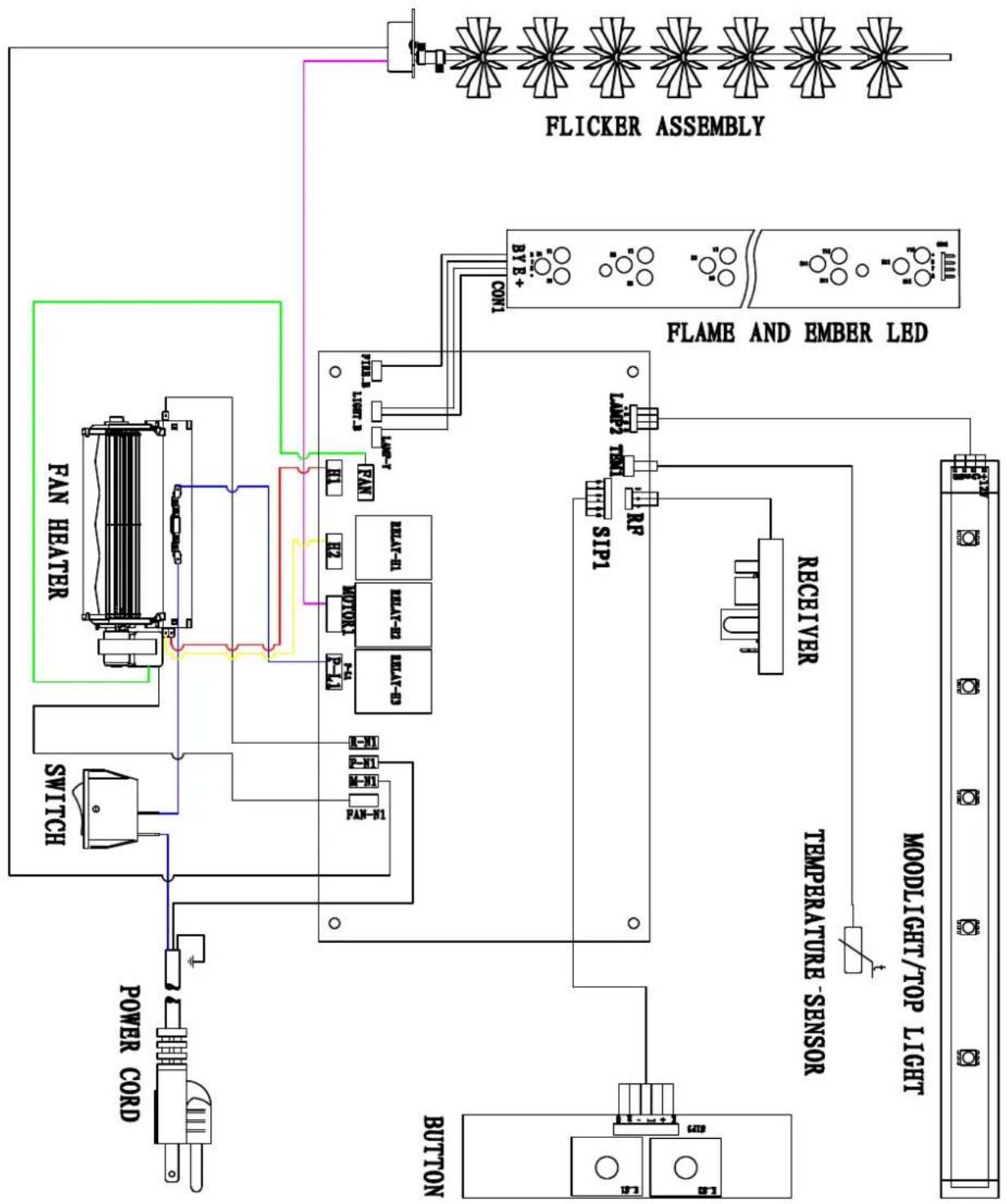
flowchart
graph TD
    A["POWER CORD"] --> B["Switch"]
    B --> C["FAN HEATER"]
    C --> D["RET-1"]
    C --> E["RET-2"]
    C --> F["RET-3"]
    C --> G["RET-4"]
    C --> H["RET-5"]
    C --> I["RET-6"]
    C --> J["RET-7"]
    C --> K["RET-8"]
    C --> L["RET-9"]
    C --> M["RET-10"]
    C --> N["RET-11"]
    C --> O["RET-12"]
    C --> P["RET-13"]
    C --> Q["RET-14"]
    C --> R["RET-15"]
    C --> S["RET-16"]
    C --> T["RET-17"]
    C --> U["RET-18"]
    C --> V["RET-19"]
    C --> W["RET-20"]
    C --> X["RET-21"]
    C --> Y["RET-22"]
    C --> Z["RET-23"]
    C --> AA["RET-24"]
    C --> AB["RET-25"]
    C --> AC["RET-26"]
    C --> AD["RET-27"]
    C --> AE["RET-28"]
    C --> AF["RET-29"]
    C --> AG["RET-30"]
    C --> AH["RET-31"]
    C --> AI["RET-32"]
    C --> AJ["RET-33"]
    C --> AK["RET-34"]
    C --> AL["RET-35"]
    C --> AM["RET-36"]
    C --> AN["RET-37"]
    C --> AO["RET-38"]
    C --> AP["RET-39"]
    C --> AQ["RET-40"]
    C --> AR["RET-41"]
    C --> AS["RET-42"]
    C --> AT["RET-43"]
    C --> AU["RET-44"]
    C --> AV["RET-45"]
    C --> AW["RET-46"]
    C --> AX["RET-47"]
    C --> AY["RET-48"]
    C --> AZ["RET-49"]
    C --> BA["RET-50"]
    C --> BB["RET-51"]
    C --> BC["RET-52"]
    C --> BD["RET-53"]
    C --> BE["RET-54"]
    C --> BF["RET-55"]
    C --> BG["RET-56"]
    C --> BH["RET-57"]
    C --> BI["RET-58"]
    C --> BJ["RET-59"]
    C --> BK["RET-60"]
    C --> BL["RET-61"]
    C --> BM["RET-62"]
    C --> BN["RET-63"]
    C --> BO["RET-64"]
    C --> BP["RET-65"]
    C --> BQ["RET-66"]
    C --> BR["RET-67"]
    C --> BS["RET-68"]
    C --> BT["RET-69"]
    C --> BU["RET-70"]
    C --> BV["RET-71"]
    C --> BW["RET-72"]
    C --> BX["RET-73"]
    C --> BY["RET-74"]
    C --> BZ["RET-75"]
    C --> CA["RET-76"]
    C --> CB["RET-77"]
    C --> CC["RET-78"]
    C --> CD["RET-79"]
    C --> CE["RET-80"]
    C --> CF["RET-81"]
    C --> CG["RET-82"]
    C --> CH["RET-83"]
    C --> CI["RET-84"]
    C --> CJ["RET-85"]
    C --> CK["RET-86"]
    C --> CL["RET-87"]
    C --> CM["RET-88"]
    C --> CN["RET-89"]
    C --> CO["RET-90"]
    C --> CP["RET-91"]
    C --> CE
    style A fill:#f9f,stroke:#333
    style B fill:#ccf,stroke:#333
    style C fill:#cfc,stroke:#333
    style D fill:#fcc,stroke:#333
    style E fill:#fcc,stroke:#333
    style F fill:#fcc,stroke:#333
    style G fill:#fcc,stroke:#333
    style H fill:#fcc,stroke:#333
    style I fill:#fcc,stroke:#333
    style J fill:#fcc,stroke:#333
    style K fill:#fcc,stroke:#333
    style L fill:#fcc,stroke:#333
    style M fill:#fcc,stroke:#333
    style N fill:#fcc,stroke:#333
    style O fill:#fcc,stroke:#333
    style P fill:#fcc,stroke:#333
    style Q fill:#fcc,stroke:#333
    style R fill:#fcc,stroke:#333
    style S fill:#fcc,stroke:#333
    style T fill:#fcc,stroke:#333
    style U fill:#fcc,stroke:#333
    style V fill:#fcc,stroke:#333
    style W fill:#fcc,stroke:#333
    style X fill:#fcc,stroke:#333
    style Y fill:#fcc,stroke:#333
    style Z fill:#fcc,stroke:#333
    style AA fill:#fcc,stroke:#333
    style AB fill:#fcc,stroke:#333
    style AC fill:#fcc,stroke:#333
    style AD fill:#fcc,stroke:#333
    style AE fill:#fcc,stroke:#333
    style AF fill:#fcc,stroke:#333
    style AG fill:#fcc,stroke:#333
    style AH fill:#fcc,stroke:#333
    style AI fill:#fcc,stroke:#333
    style AJ fill:#fcc,stroke:#333
    style AK fill:#fcc,stroke:#333
    style AL fill:#fcc,stroke:#333
    style AM fill:#fcc,stroke:#333
    style AN fill:#fcc,stroke:#333
    style AO fill:#fcc,stroke:#333
    style AP fill:#fcc,stroke:#333
    style AQ fill:#fcc,stroke:#333
    style AR fill:#fcc,stroke:#333
TROUBLE SHOOTING
| PROBLEM | POSSIBLE CAUSE | SOLUTION |
| Dim or no flame | Flame LED's are burnt out | Inspect the LED's and replace them if necessary. |
| Ember bed is not glowing or dimming | Ember LED's are burnt out | Inspect the ember bed LED's and replace them if necessary. |
| Appliance turns off and will not turn on | Appliance has overheated and safety device has caused the thermal switch to disconnect | Turn off the main switch, allow appliance to cool for 10 minutes, then turn it on. |
| House circuit breaker has tripped | Reset house circuit breaker. | |
| Appliance's fuse has blown | Replace the fuse. | |
| Appliance will not come on when switch is flipped to ON | Appliance is not plugged into an electrical outlet | Check plug and plug in. |
| Appliance has overheated and safety device has caused the thermal switch to disconnect | Turn off the main switch, allow appliance to cool for 10 minutes, then turn it on. | |
| Circuit board is burnt out | Inspect the circuit board and replace it if necessary. | |
| No warm air coming out of appliance | Heater is burnt out | Inspect the burner and heater assembly and replace it if necessary. |
| Flame sputters | Flame motor is defective. | Call a qualified service technician and replace flame motor. |
| Remote Control does not work. | Low batteries. Unit switch in “O” position. | Replace AAA batteries in remote control. Turn the switch in “I” position. |
| Flame is fixed. | Wiring may be loose or the flame motor may be defective. |
SERVICE HISTORY
This heater must be serviced annually depending on usage.
| Date | Dealer Name | Service technician Name | Service Performed | Special Concerns |
NOTES:
WARRANTY FOR PRODUCTS MANUFACTURED AFTER JANUARY 1st, 2016
Amantii Imports Corp. ("Amantii") warrants that your newly purchased Amantii electric fireplace is free from manufacturing and material defects for a period of two (2) years from the date of the first purchase, subject to the conditions and limitations contained below.
Warranty Application & Exclusions
This limited warranty applies to your newly purchased Amantii electric fireplace; the limited warranty's application is limited to purchases made in any province of Canada or in any of the 52 States of the United States of America, including the District of Columbia. Only the original purchaser of the product is eligible for coverage under this limited warranty; the warranty is not transferable.
Products excluded from this limited warranty
Light bulbs are not covered by this limited warranty and are the sole responsibility of the owner/purchaser. Amantii does not cover service or labor charges.
Warranty Coverage and Term
Products covered by this limited warranty have been tested and inspected prior to shipment and, subject to the provisions of this warranty, Amantii warrants such products to be free from defects in material and workmanship for a period of two (2) years from the date of the first purchase of such products.
The limited two (2) year warranty period for products also applies to any implied warranties that may exist under applicable law. Some jurisdictions do not allow limitations on how long an implied warranty lasts, so the above limitation may not apply to the purchaser.
All other warranties—expressed or implied—with respect to the product, its components and accessories or any obligation/liabilities on the part of Amantii are hereby expressly excluded.
Limitations to Coverage Under Limited Warranty
This limited warranty does not apply to products that have been repaired, except by Amantii or its authorized service representatives, or otherwise altered. This limited warranty further does not apply to defects resulting from misuse, abuse, accident, neglect, incorrect installation, improper maintenance or handling, or operation with an incorrect power source. Products made by other manufacturers, sold with the product or thereafter, are not covered by this limited warranty. The use of unauthorized components will render this warranty null and void.
Panorama Outdoor Units
All Panorama units that are installed outdoors or in moisture intense conditions must use the stainless steel cover. Proof of purchase of the cover is required for any warranty claims.
Defects
Defects must be brought to the attention of the selling dealer. Please have your proof of purchase, catalogue/model and serial numbers available when contacting dealer; any and all service under the limited warranty requires a proof of purchase of the product. Should a product or part covered by this limited warranty be proven to be defective, in material or workmanship, and during the two (2) year limited warranty period, Amantii will replace such defective product or part without charge. If Amantii is unable to replace such product, or if replacement is not commercially practicable or cannot be timely done, in its sole discretion Amantii may, in lieu of replacement, choose to refund the purchase price for such product or part. Amantii does not cover labor or service charges to replace said parts.
Limitations
In no event will Amantii, including without limitation any of its directors, officers, shareholders, employees, consultants, agents, heirs, executors, administrators and assigns, be liable to the purchaser or any third party, whether in contract, in tort, or on any other basis for any indirect, special, punitive, exemplary, consequential, or incidental loss, cost or damage arising out of or in connection with the sale, maintenance, use or inability to use the product, even if Amantii, including without limitation any of its directors, officers, shareholders, employees, consultants, agents, heirs, executors, administrators and assigns, have been advised of the possibility of such losses, costs or damages, or if such losses, costs or damages are foreseeable. In no event will Amantii, including without limitation any of its directors, officers, shareholders, employees, consultants, agents, heirs, executors, administrators and assigns, be liable for any direct losses, costs or damages that exceed the purchase price of the product.
Some jurisdictions do not allow the exclusion or limitation of incidental or consequential damages, so the above limitation or exclusion may not apply to the purchaser.
Application of Provincial and State Law
This limited warranty gives you specific legal rights, and you may also have other rights which vary from jurisdiction to jurisdiction. The provisions of the United Nations Convention on Contracts for the Sale of Goods shall not apply to this limited warranty or the sale of products covered by this limited warranty.
General
Amantii reserves the right to make changes at any time without notice, in design, material, specifications, prices and the right to discontinue styles and products.