SDSFX3113-111-LRT - Seau Milan - Free user manual and instructions
Find the device manual for free SDSFX3113-111-LRT Milan in PDF.

User questions about SDSFX3113-111-LRT Milan
0 question about this device. Answer the ones you know or ask your own.
Ask a new question about this device
Download the instructions for your Seau in PDF format for free! Find your manual SDSFX3113-111-LRT - Milan and take your electronic device back in hand. On this page are published all the documents necessary for the use of your device. SDSFX3113-111-LRT by Milan.
USER MANUAL SDSFX3113-111-LRT Milan
Industrial Device Server
SDSFX3113-111-LRT and SDSFX3114-111-LRT
Serial Device Servers
User Guide
natural_image
Black industrial device labeled 'TRANSITION NETWORKS' with ventilation grille (no readable text beyond branding)33608 Rev. A
Version 1.11
May 2015
Contents
1. GETTING TO KNOW YOUR DEVICE SERVER....3
1.1 About the SDSFX311x-111-LRT Serial Device Server ....3
1.2 Software Features....4
1.3 Hardware Features .... 4
2. HARDWARE INSTALLATION 5
2.1 Install SDSFX311x-111-LRT on DIN-Rail....5
2.2 Wall Mounting Installation 6
3. HARDWARE OVERVIEW 8
3.1 Front Panel....8
3.2 Front Panel LEDS 9
3.3 Top Panel 9
3.4 Bottom Panel 10
4. CABLES....12
4.1 Fiber Ethernet Cables....12
5. POWER SOURCES 13
6. MANAGEMENT INTERFACE 15
5.1 SDS-Manager....15
5.2 Configuration by Web Browser 46
5.1.2 Uninstall the SDS Manager....56
5.1.3 Messages....56
5.3 Configuration by SSH Console 57
7. TECHNICAL SPECIFICATIONS....62
8. TROUBLESHOOTING ....65
Troubleshooting Q&A....66
9. SAFETY WARNINGS AND CAUTIONS....67
10. SERVICE, WARRANTY AND TECH SUPPORT....68
Contact Us....68
Warranty 68
11. COMPLIANCE CERTIFICATIONS....71
Declaration of Conformity....71
European Regulations 72
Electrical Safety Warnings 73
Record of Revisions....74
1. Getting to Know Your Device Server
1.1 About the SDSFX311x-111-LRT Serial Device Server
The SDSFX311x-111-LRT is an innovative 1 port RS232/422/485 to 1 port fiber optical device
server. The network fiber port can be multi-mode
(SDSFX3113-111-LRT) or single mode (SDSFX3114-111-LRT) for different transmission distances. To assure the agility and security of critical data, the SDSFX311x-111-LRT device servers offer many powerful features for SW redundancy.
The SDSFX311x-111-LRT device servers can simultaneously transfer data to 5 host PCs. This feature can assure all critical data is saved on different servers to avoid loss of data in the event of a network segment or server failure.

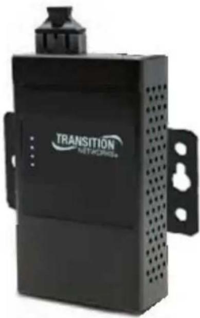
natural_image
Black industrial device labeled 'TRANSITION NETWORKS' with no visible text or symbols on its bodyThe SDSFX311x-111-LRT device servers provide dual redundant power inputs on the DC power jack and terminal block. The SDSFX311x-111-LRT device servers also provide a NAT pass through function so that you are able to manage the SDSFX311x-111-LRT device servers inside or outside the NAT router. It is easy for different IP domains to use SDSFX311x-111-LRT device servers. You can configure and manage the devices by using the SDS-Manager application.
These product numbers are covered in this manual:
SDSFX3113-111-LRT: one 100BASE-FX 1310nm MM (SC) (2 km/1.2 mi.) and one RS232/422/485 DB9 port.
SDSFX3114-111-LRT: one 100BASE-FX 1310nm SM (SC) (30 km/18.6 mi.) and one RS232/422/485 DB9 port.
1.2 Software Features
■ NAT Pass-through: Lets you manage the SDSFX311x-111-LRT device servers with a NAT router.
■ Redundant Power Inputs: 12\~48VDC on terminal block.
■ Redundant multiple host devices: five simultaneous connections via Virtual COM, TCP Server, TCP Client mode, UDP.
■ Secured Management by HTTPS and SSH.
■ Versatile Modes: Virtual Com, Serial Tunnel, TCP Server, TCP Client, UDP.
■ Event Warning via Syslog, Email, and SNMP traps.
■ Windows OSes supported: Windows NT/2000/ XP/ 2003/VISTA 32bits/Windows 7 (32/64 bits).
1.3 Hardware Features
■ Redundant Power Inputs: 12\~48 VDC on terminal block and power jack.
■ Operating temperature: -40^ to +70^
■ Storage Temperature: -40 to 85°C.
■ Operating Humidity: 5% to 95%, non-condensing.
■ Casing: IP-30.
■ One 10/100Base-FX Ethernet port.
■ Dimensions: Width: 2.83" (72mm); Depth: 1.16" (29.4 mm); Height: 4.86" (123.4 mm).
■ Device Weight: 0.72 lbs. (0.327 kg).
2. Hardware Installation
2.1 Install SDSFX311x-111-LRT on DIN-Rail
Each SDSFX311x-111-LRT has a Din-Rail clip on rear panel. The Din-Rail clip can be used to mount the SDSFX311x-111-LRT on a 35mm Din-Rail.
2.1.1 Mount SDSFX311x-111-LRT on DIN-Rail
Step 1: Slant the SDSFX311X-111-LRT and position the metal spring behind the top edge of the Din-Rail.
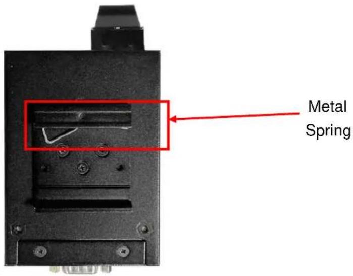
text_image
Metal SpringStep 2: Push the SDSFX311X-111-LRT down on the Din-Rail until the bottom of the clip grips the bottom edge of the DIN Rail. You may hear a "click" sound when this happens.
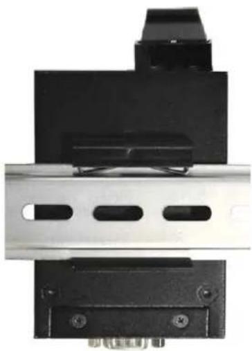
natural_image
Mechanical component with black and metallic parts, no visible text or symbols2.2 Wall Mounting Installation
Each SDSFX311x-111-LRT also contains a wall mount bracket that can be found in the package. The following steps show how to mount the SDSFX311x-111-LRT on a panel or wall:
2.2.1 Mount SDSFX311x-111-LRT on wall
Step 1: Remove the Din-Rail by removing the 3 screws.
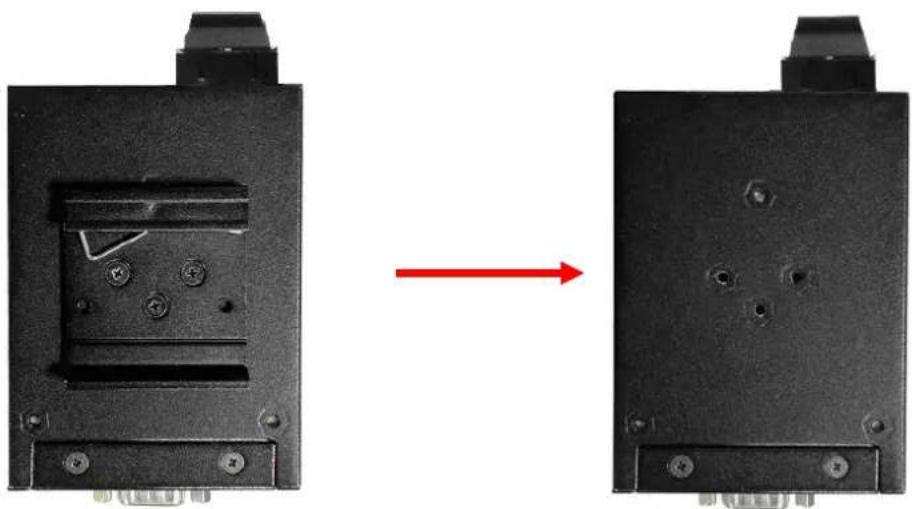
natural_image
Two black electronic components with mounting holes and a red arrow indicating transformation (no text or symbols)Figure 2-3
Step 2: Use the screws that can be found in the package to install the wall mount bracket.

natural_image
Close-up of a black mechanical component with mounting holes and a small protrusion (no visible text or symbols)Figure 2-4
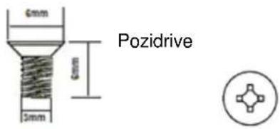
The screws specification shows in the following two pictures. In order to prevent SDSFX311x-111-LRT from any damage, the size of screws should not be larger than the size that used for the DIN Rail clip.
text_image
6mm 6mm 5mm PozidriveFigure 2-5
Step 3: Mount the SDSFX311x-111-LRT on a panel or wall using the holes in the wall mount bracket.
natural_image
Black industrial device labeled 'TRANSITION NET-ACRMS' with ventilation slots and mounting bracket (no readable text beyond branding)Figure 2-6
3. Hardware Overview
3.1 Front Panel
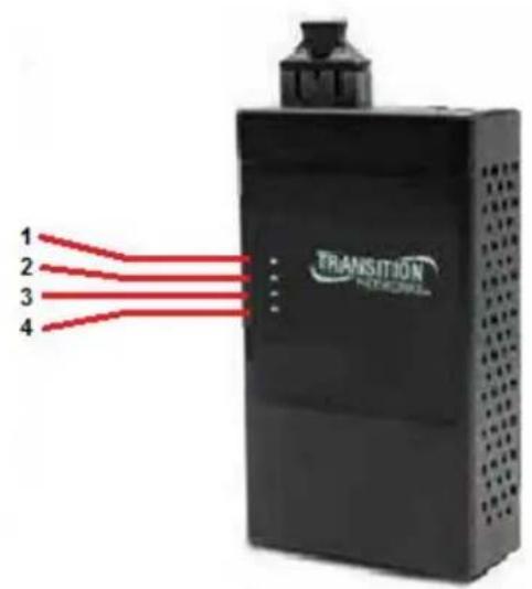
text_image
1 2 3 4 TRANSITION NETWORKSFigure 3-1
- LED for PWR1 and system status. When the PWR1 links, the green LED will light.
- LED for PWR2 and system status. When the PWR2 links, the green LED will light.
- LED of 100Base-FX Ethernet port.
- LED of serial port. Green for transmitting, red for receiving
3.2 Front Panel LEDS
The following table describes the SDSFX311x-111-LRT front panel LEDs.
| LED | Color | Status | Description |
| PWR1 Green/Red | On DC power 1 activated. | ||
| Red blinking | Indicates an IP conflict, or DHCP or BOOTP server did not respond properly | ||
| PWR2 Green/Red | On DC power 2 activated. | ||
| Red blinking | Indicates an IP conflict, or DHCP or BOOTP server did not respond properly | ||
| ETH | Green | Green On/Blinking | 100Mbps LNK/ACT |
| Serial | Green | Blinking | Serial port is transmitting data |
| Red | Blinking | Serial port is receiving data |
Table 3-1 Front panel LEDs
3.3 Top Panel
The Top panel components of SDSFX311x-111-LRT are shown as below:
- Terminal block includes: PWR1 (12 \~ 48V DC)
- Power Jack includes: PWR2 (12 \~ 48V DC)
- 100Base-FX Ethernet interface.

text_image
DC12-48V PWR1 PWR2 G V-V+ +Figure 3-2
3.4 Bottom Panel
The bottom panel components of IDS-5011F are shown as below:

text_image
1 2 3 Reset Serial Port ON 1 2Figure 3-3
- Reset button. Press for 5 seconds to restore factory default settings.
- Male DB9 connector: Serial interface of RS-232/422/485 (2 wire)(4 wire).
DB9 Connector
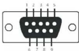
text_image
1 2 3 4 5 6 7 8 9| Pin # RS | 232 RS 422 | RS 485(4 wire) | RS 485(2 wire) | |
| 1 DCD RXD | - RXD - | |||
| 2 RXD RXD | + RXD + | |||
| 3 | TXD | TXD + | TXD + | DATA + |
| 4 | DTR | TXD - | TXD - | DATA - |
| 5 | GND | GND | GND | GND |
| 6 DSR | ||||
| 7 | RTS | |||
| 8 | CTS | |||
| 9 | RI | |||
| RS 232 mod act as DTE | ||||
Table 3-2 Pin assignment

- DIP Switch: Termination for RS-422/485
| DIP 1 DIP | 2 | Termination Configuration |
| ON | ON | Termination for long distance 4-wire RS485/422 |
| ON | OFF | Reserved |
| OFF | ON | Termination for long distance 2-wire RS485 |
| OFF | OFF | No termination for RS485/ 422 (short distance) |
Table 3-2 DIP Switch
4. Cables
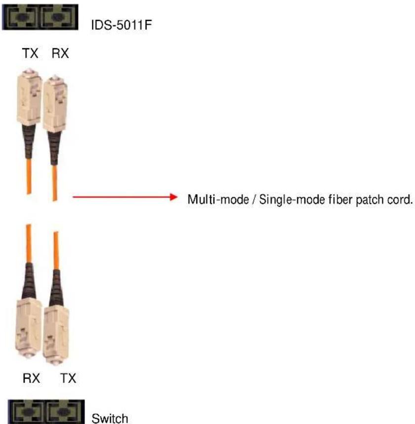
4.1 Fiber Ethernet Cables
The SDSFX311x-111-LRT device servers have one fiber optical port. The fiber optical port is multi-mode (0 to 2 km, 1310 nm, 50/125 μm to 62.5/125 μm) or single-mode (0 to 30 km, 1310 nm, 9/125 μm) with SC connector. Please remember that the TX port of SDSFX311x-111-LRT device servers should be connected to the RX port of Switch and vice versa.
text_image
IDS-5011F TX RX Multi-mode / Single-mode fiber patch cord. RX TX Switch5. Power Sources
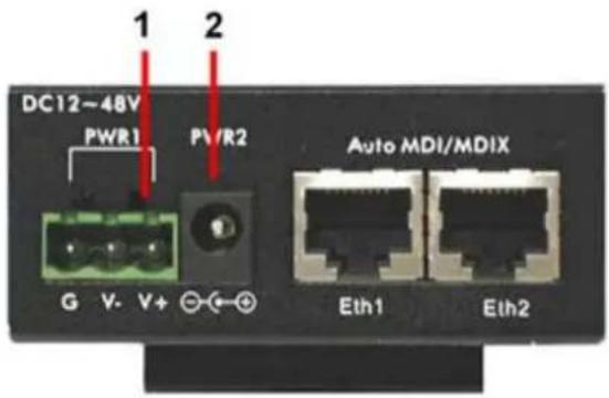
Power Source Options
The SDSFX311x-111-LRT device servers provide 2 different methods of supplying input power.
- Terminal block include: PWR1 (12 \~ 48V DC)
- Power Jack include: PWR2 (12 \~ 48V DC)
text_image
DC12~48V PWR1 PV/R2 Auto MDI/MDIX G V-V+ ⊙←⊕ Eth1 Eth2Power Supply Options
Depending on the use and location for the serial device server, two different power supply options are recommended.
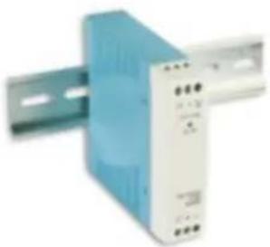
25135 DIN Rail Mounted Power Supply
The DIN rail power supply is best suited for usage in non-climate controlled environments. In these environments equipment is normally installed inside equipment cabinets with DIN rails for mounting.
Basic Specs:
Input Voltage: 85\~264VAC or
120\~370VDC
Output Voltage: 24VDC
Rated Power: 10 Watts
Operating Temperature: -40°C to +70°C
Screw terminal power connections
natural_image
Exterior view of a blue industrial power supply unit with mounting bracket (no visible text or symbols)SPS-UA12DHT Shelf Mounted Power Supply
The shelf mounted power supply is best suited to areas where the device server may be mounted to a wall and use a standard A/C outlet for powering the device.
Basic Specs:
Input Voltage: 90\~264VAC
Output Voltage: 12VDC
Rated Power: 18 Watts
Operating Temperature: 0°C to +70°C
Standard A/C plug and barrel connector

natural_image
Black rectangular electronic device with coiled cable and connector (no visible text or symbols)6. Management Interface

SDS-Manager_20150203.exe
5.1 SDS-Manager
The SDS-Manager is a powerful Windows utility that supports serial device server discovery, device configuration, group setup, group firmware update, monitoring functions, etc. It makes it easy to install and configure devices over the network.
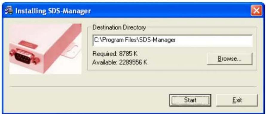
5.1.1 Install ISDS-Manager
Installing SDS-Manager requires approximately 8785 K of PC memory.
The default Destination Directory is C:\Program Files\SDS-Manager.
Step 1: Execute the Setup program; double-click on the SDS-Manager_20150203.exe file.
Step 2: Click "start" after selecting the folder for SDS-Manager.
text_image
Installing SDS-Manager Destination Directory C:\Program Files\SDS-Manager Required: 8785 K Available: 2289556 K Browse... Start ExitStep 3: When the installation completes successfully, click "OK".

text_image
Installing SDS-Manager Installation was completed successfully. OKStep 4: Check to launch the SDS-Manager either Now or Later.
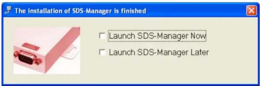
text_image
The installation of SDS-Manager is finished Launch SDS-Manager Now Launch SDS-Manager LaterStep 5: At the Confirmation dialog, click the Yes button to restart your computer immediately, or click No to restart your computer later.
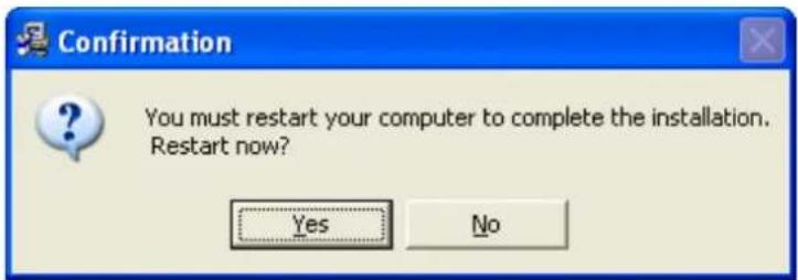
text_image
Confirmation You must restart your computer to complete the installation. Restart now? Yes NoStep 6: Double-click the he SDS-Manager icon in the icon tray to display the startup screen.

text_image
SDS-Manager 3:41 PM Tuesday 3/10/20155.1.2 Using SDS-Manager
5.1.2.1 Explore Device Servers
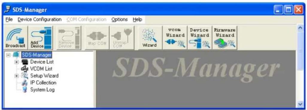
The SDS-Manager startup screen is shown below.
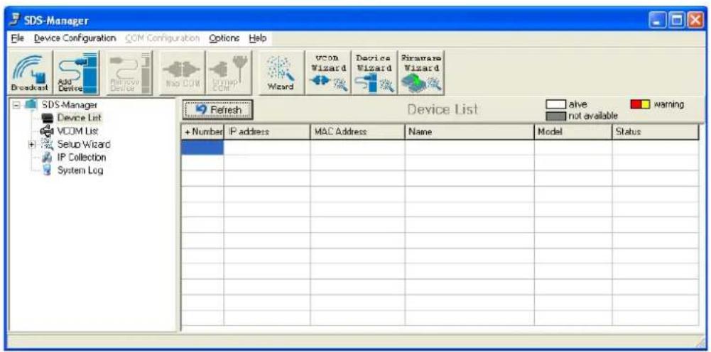
text_image
SDS-Manager File Device Configuration CCM Configuration Options Help Broadcast Add Device Remove Device Import CDM Setup CDM Wizard VCOM Wizard Device Wizard Firmware Wizard SDS-Manager Device List VCOM List Setup Wizard IP Collection System Log Refresh Device List alive warning + Number IP address MAC Address Name Model Status Number IP address Name Model StatusBroadcast button: If you click the Broadcast button, the SDS-Manager will broadcast to the network and search all available DS devices in the network. The default IP address of the device is "192.168.1.77"; select the device you wish to use and click the "Add" button.
Add Device button: select the device you wish to use and click the "Add Device" button.
You can set Static IP address or in DHCP client mode to get an IP address automatically. When done, click the "OK" button to add the device.

text_image
Broadcast Searching New Devices 172.16.44 130 00:1E:94:01:EAD3 Inveld IP Locked 172.16.44 131 00:1E:94:01:A956 Inveld IP Locked 172.16.44 172.16.47 MAC: 00:1E:94:01:EAD3 Original IP: 172.16.44 130 ✓ Using Static IP □ Using DHCP Assign Static IP IP Address: 172.16.44 130 Network: 255.255.255.0 Gateway: 172.16.44 130 DNS1: DNS2: Auto Scan Password: Cancel OK Add Your best click here SOS Manager Device List VCOM List Setup Wizard IP Collection System Log + New Cancel Model Status alive not available warningThe added device displays in the Device List:
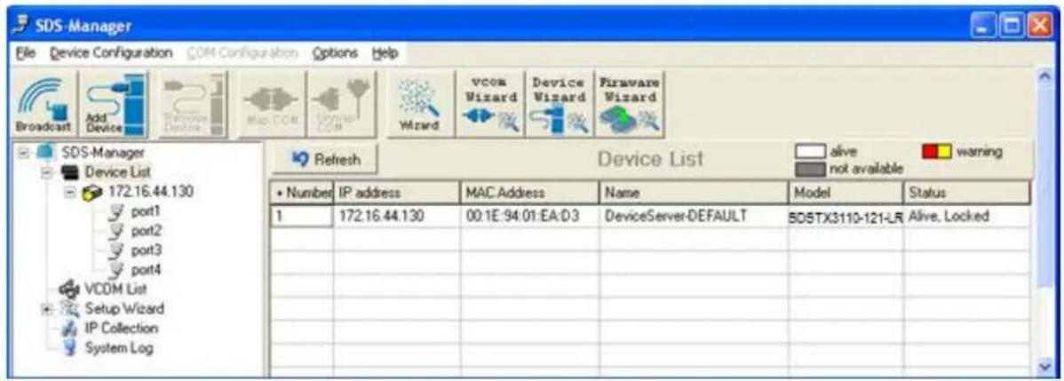
text_image
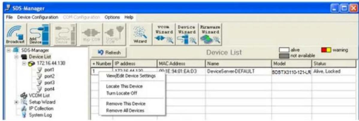
SDS-Manager File Device Configuration COM Configuration Options Help Broadcast Add Device Remove Device Map COM Wizard vcom Wizard Device Wizard Firmware Wizard SDS-Manager Device List 172.16.44.130 port1 port2 port3 port4 VCOM List Setup Wizard IP Collection System Log Refresh Device List alive warning not available + Number IP address MAC Address Name Model Status 1 172.16.44.130 00:1E:94:01:EA:D3 DeviceServer-DEFAULT 50STX3110-121-LR Alive, LockedOn the Device List, right click a device to display its options.
text_image
SDS-Manager File Device Configuration COM Configuration Options Help Broadcast Add Device Remove Device Map COM Window COM Wizard vcom Wizard Device Wizard Firmware Wizard SDS-Manager Device List 172.16.44.130 port1 port2 port3 port4 VCOM List Setup Wizard IP Collection System Log Refresh Device List alive warning not available + Number IP address MAC Address Name Model Status 1 172.16.44.130 00.1E-94.01.EA:03 DeviceServer-DEFAULT 50STX3110-121-LR Alive, Locked View/Edit Device Settings Locate This Device Turn Locate Off Remove This Device Remove All DevicesThe options displayed are:
View/Edit Device Settings: displays the Configure Device Servers page and its tabs.
Locate This Device: attempts to locate the device.
Turn Locate Off: turns off the attempt to locate device information.
Remove This Device: deletes the selected instance from the Device List.
Remove All Devices: deletes all configured instances from the Device List.
5.1.2.2 Configure Device Servers
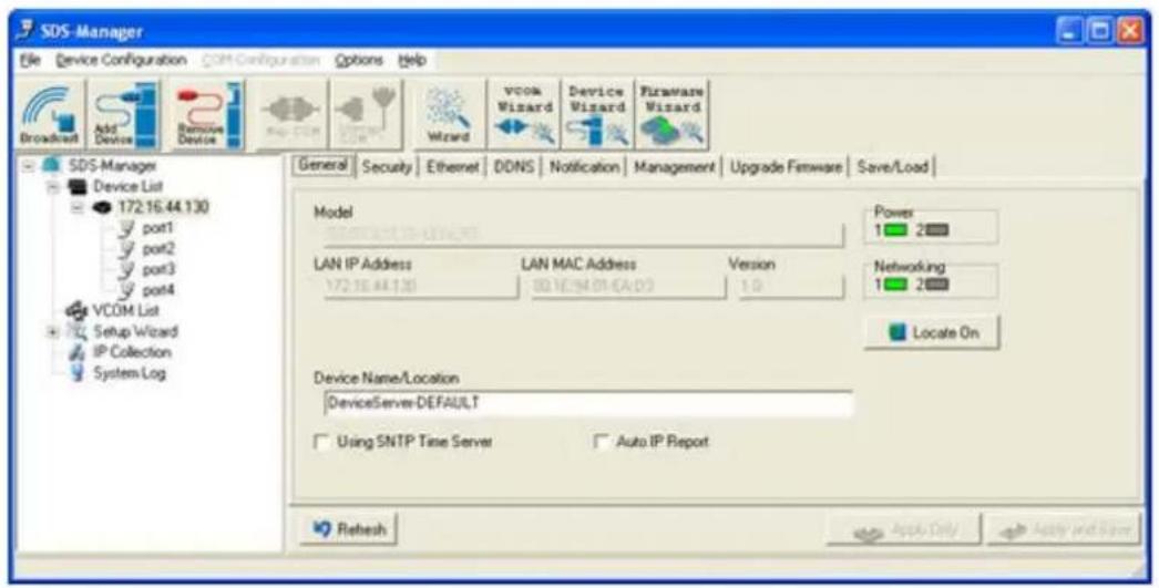
General tab
This page lets you set the device name, SNTP server and Auto IP Report.
text_image
SDS-Manager File Device Configuration COM-Configuration Options Help Broadcast Add Device Remove Device Map COM Wizard vcom Wizard Device Wizard Firmware Wizard General Security Ethernet DDNS Notification Management Upgrade Firmware Save/Load Model LAN IP Address LAN MAC Address Version 172.16.44.130 00.16.94.01 (CA:03) 1.0 Power 1 2 Networking 1 2 Locate On Device Name/Location DeviceServer-DEFAULT Using SNTP Time Server Auto IP Report Refresh Apply Only Apply and SaveFigure 5-5 General settings tab
The following table describes the labels in this screen.
| Label Description | |
| Device Name/Location | You can set the device name or related information. Click the “Locate On” button to locate the serial server’s position. |
| SNTP Time Server | Input the SNTP server domain name or IP address, port and select the Time zone. |
Table 5-1 General settings
The IP collection option shows the device server status. The default report interval is 0, indicating disabled, but you can set the other IP or Port.
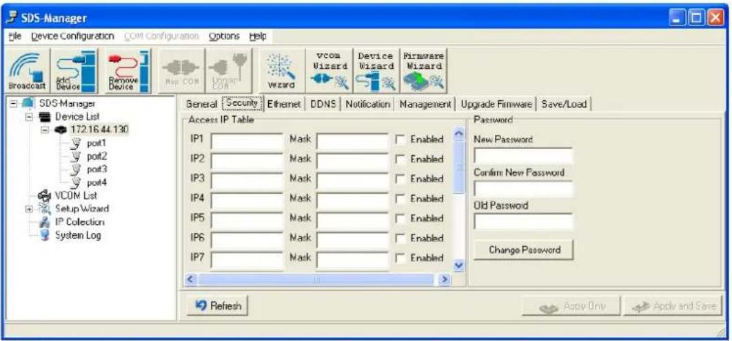
Security tab
text_image
SDS-Manager File Device Configuration COM Configuration Options Help Broadcast Add Device Remove Device Map COM Unwim COM Wizard vcom Wizard Device Wizard Firmware Wizard General Security Ethernet DDNS Notification Management Upgrade Firmware Save/Load Access IP Table IP1 Mask Enabled IP2 Mask Enabled IP3 Mask Enabled IP4 Mask Enabled IP5 Mask Enabled IP6 Mask Enabled IP7 Mask Enabled Password New Password Confirm New Password Old Password Change Password Refresh Apply Only Apply and SaveFigure 5-6 Security tab
The following table describes the labels in this screen.
Table 5-2 Security tab
| Label Description | |
| Accessible IP Table | To prevent unauthorized access by setting host IP addresses and network masks. |
| Password settings | You can set the password to prevent unauthorized access from your server. The factory default is no password. |
Note: The username for the device server login can be changed when using the WEB interface. The username cannot be changed within SDS-Manager. The default username is root.
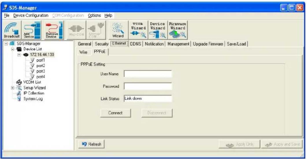
Ethernet tab - PPoE
The PPoE tab is shown below.
text_image
SDS-Manager File Device Configuration COMConfiguration Options Help Broadcast Add Device Remove Device Map-COM Unmap COM Wizard vcom Wizard Device Wizard Firmware Wizard SDS-Manager Device List 172.16.44.130 port1 port2 port3 port4 VCOM List Setup Wizard IP Collection System Log General Security Ethernet DDNS Notification Management Upgrade Firmware Save/Load Wire PPPoE PPPoE Setting User Name Password Link Status Link down Connect Disconnect Refresh Apply Only Apply and SaveFigure 5-7 Ethernet tab - PPoE
| Label Description | |
| User Name | Entry field for the user's name. |
| Password Entry field for the user's password. | |
| Link Status | Displays the current link status (e.g., Link up or Link down). |
| Connect button Click to make the connection when complete. | |
Ethernet tab - Wire
The Wire tab is shown below.

text_image
SDS-Manager File Device Configuration COM Configuration Options Help Broadcast Add Device Remove Device Map COM UMAP COM Wizard vcom Wizard Device Wizard Firmware Wizard SDS-Manager Device List 172.16.44.130 port1 port2 port3 port4 VCOM List Setup Wizard IP Collection System Log General Security Ethernet DDNS Notification Management Upgrade Firmware Save/Load Wire PPPoE Using Static IP Using DHCP/BOOTP Static IP Settings IP Address 172.16.44.130 Netmask 255.255.252.0 Gateway 172.16.44.21 DNS1 172.16.44.151 DNS2 Refresh Apply Only Apply and SaveFigure 5-7 Ethernet tab - Wire
| Label Description | |
| Using Static IP | Allows manually assigning an IP address. |
| Using DHCP/BOOTP | IP Address automatically assigned by a DHCP server in your network. |
| IP Address | The device's IP address. |
| Netmask | All devices on the network must have the same subnet mask to communicate on the network. |
| Gateway | Enter the IP address of the router in your network. |
| DNS 1 / DNS 2 | Enter the IP address of the DNS server; The DNS server translates domain names into IP addresses. |
DDNS tab
Here you can enable or disable DDNS globally and configure DDNS settings.
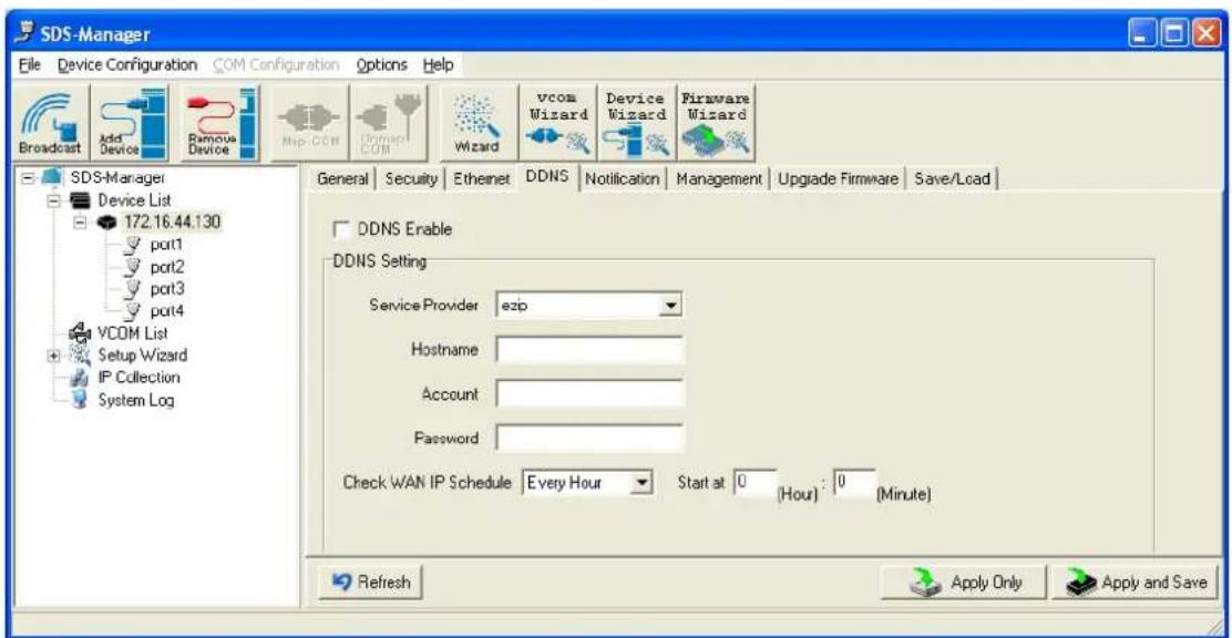
text_image
SDS-Manager File Device Configuration COM Configuration Options Help Broadcast Add Device Famous Device Map COM Domain COM Wizard vcom Wizard Device Wizard Firmware Wizard SDS-Manager Device List 172.16.44.130 port1 port2 port3 port4 VCOM List Setup Wizard IP Collection System Log General Security Ethernet DDNS Notification Management Upgrade Firmware Save/Load DDNS Enable DDNS Setting Service Provider ezip Hostname Account Password Check WAN IP Schedule Every Hour Start at 0 (Hour) : 0 (Minute) Refresh Apply Only Apply and SaveFigure 5-8 DDNS tab
| Label Description | |
| DDNS Enable | Enable or Disable DDNS (Dynamic DNS) on a global basis (at the system level). The default is Disabled. |
| Service Provider | At the dropdown select ezip, pgpow, dhs, constanttime, dyndns, dyndns-static, dyndns-custom, ods, tzo, easydns, easydns-partner, gnudip, justlinux, dyns, hn, zoneedit, heipv6tb, or 3322. |
| Hostname | Set the device name or related information. |
| Account | The serial server's position. |
| Password | You can set the password to prevent unauthorized access from your server. The factory default is no password. |
| Check WAN IP Schedule | At the dropdown select every hour, day, week or month and select the start time in hours and minutes. |
Notification tab - SNMP Trap
Here you can specify the events that should be sent to the administrator of events alarmed by SNMP trap, Email Notification, Syslog Notification, and or Fault LED/Relay.
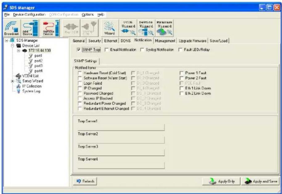
text_image
SDS Manager File Device Configuration COM Configuration Options Help Broadcast Add Device SoftMode Device Map COM Upgrade Wizard Wizard VCOM Wizard Device Wizard Microcare Wizard General Security Ethernet DDNS Notification Management Upgrade Firmware Save/Load SNMP Trap Email Notification Syslog Notification Fault LED/Relay SNMP Settings: Notified Items: Hardware Reset (Cold Start) 0_1 Changed Power 1 Fault Software Reset (Warm Start) 0_2 Changed Power 2 Fault Login Failed 0_3 Changed PCE Fault IP Changed 0_4 Changed Eth 1 Link Down Password Changed 0_1 Changed Eth 2 Link Down Access IP Blocked 0_2 Changed Redundant Power Changed 0_3 Changed Redundant Ethernet Changed 0_4 Changed Trap Server1 Trap Server2 Trap Server3 Trap Server4 Refresh Apply Only Apply and SaveFigure 5-8 Notification tab - SNMP Trap
The following table describes the labels in this screen.
| Label Description | |
| SNMP Trap | To notify events by SNMP trap. |
| Email Notification | To notify events by Email. |
| Syslog Notification To notify events by Syslog. | |
| Notified Items | Events to be notified. |
| Trap Server 1-4 | The IP addres for up to four SNMP Trap Servers. |
| Apply Only | Apply current setting. |
| Apply and Save | Apply and save current setting. |
Notification tab - Email Notification
Here you can specify the events that should be sent to the administrator by E-mail.

text_image
SDS-Manager File Device Configuration COM-Configuration Options Help Broadcast Add Devices Remote Device Map COM Wizard Wizard vcom Wizard Device Wizard Firmware Wizard SDS-Manager Device List 172.16.44.130 port1 port2 port3 port4 VCOM List Setup Wizard IP Collection System Log General Security Ethernet DDNS Notification Management Upgrade Firmware Save/Load SNMP Trap Email Notification Syslog Notification Fault LED/Relay Email Settings Notified Items Hardware Reset (Cold Start) 0_1 Changed Power 1 Fault Software Reset (Warm Start) 0_2 Changed Power 2 Fault Login Failed 0_3 Changed POE Fault IP Changed 0_4 Changed Eth 1 Link Down Password Changed 00_1 Changed Eth 2 Link Down Access IP Blocked 00_2 Changed Redundant Power Changed 00_3 Changed Redundant Ethernet Changed 00_4 Changed SMTP Settings SMTP Server Port 25 Authentication Required Email List Email Address 1 Email Address 3 Sender Email Address 2 Email Address 4 Refresh Apply Only Apply and SaveFigure 5-9 Notification tab - Email Notification
The following table describes the labels in this screen.
| Label Description | |
| Email Notification | To notify events by Email. |
| Notified Items | Events to be notified. The default is all disabled (unchecked). |
| SMTP Server | The IP address of the SMTP Server. |
| Port | The SMTP Server's port number (port 25 by default). |
| Authentication Required | Checkbox to enable or disable authentication. |
| Email Address 1-4 | The Email address where notifications are to be sent. |
| Sender | The Email sernder's name. |
Notification tab - Syslog Notification
Here you can specify the events that should be notified to the administrator by System log.

text_image
SDS-Manager File Device Configuration COM Configuration Options Help Broadcast Add Device Remove Device Map COM Untrap COM Wizard vcom Wizard Device Wizard Firmware Wizard SDS Manager Device List 172.16.44.130 port1 port2 port3 port4 VCOM List Setup Wizard IP Collection System Log General Security Ethernet DDNS Notification Management Upgrade Firmware Save/Load SNMP Trap Email Notification Syslog Notification Fault LED/Relay Syslog Settings Notified Items Hardware Reset (Cold Start) D0_1 Changed Power 1 Fault Software Reset (Warm Start) D0_2 Changed Power 2 Fault Login Failed D0_3 Changed PCE Fault IP Changed D0_4 Changed Eth 1 Link Down Password Changed D0_1 Changed Eth 2 Link Down Access IP Blocked D0_2 Changed Redundant Power Changed D0_3 Changed Redundant Ethernet Changed D0_4 Changed System Log Settings Server IP Port Using Current Host's Log Server Refresh Apply Only Apply and SaveFigure 5-9 Notification tab - Syslog Notification
The following table describes the labels in this screen.
| Label Description | |
| Syslog Notification | To notify events by system log. |
| Notified Items | Events to be notified. |
| Server IP | The Syslog server's IP address. |
| Port | The Syslog server's port number (0 by default). |
| Using Current Host's Log Server | Click the button to use the local host's Syslog server. |
Notification tab - Fault LED/Relay
Here you can specify the events that should be notified to the administrator by Fault LED/Relay.
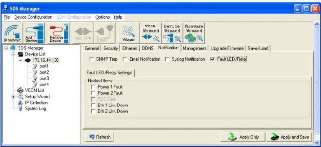
text_image
SDS-Manager File Device Configuration COM Configuration Options Help Broadcast Add Device Remove Device Map COM Unmap COM Wizard vcom Wizard Device Wizard Firmware Wizard SDS-Manager Device List 172.16.44.130 port1 port2 port3 port4 VCOM List Setup Wizard IP Collection System Log General Security Ethernet DDNS Notification Management Upgrade Firmware Save/Load SNMP Trap Email Notification Syslog Notification Fault LED/Rela Fault LED/Relay Settings Notified Items Power 1 Fault Power 2 Fault POE Fault Eth 1 Link Down Eth 2 Link Down Refresh Apply Only Apply and SaveFigure 5-10 Notification tab - Fault LED/Relay
The following table describes the labels in this screen.
| Label Description | |
| Fault LED/Relay | To notify events by fault LEDs/Relay. |
| Notified Items | Events to be notified. |
| Power 1 Fault Notification if a Power 1 fault occurs. | |
| Power 2 Fault Notification if a Power 2 fault occurs. | |
| Eth Link 1 Down Notification if Ethernet Link 1 is down. | |
| Eth Link 2 Down | Notification if Ethernet Link 2 is down. |
Management tab

text_image
SDS Manager File Device Configuration COM Configuration Options Help Broadcast ADC Devices Remove Devices Nso COM LOMP CN Wizard voca Wizard Device Wizard Firmware Wizard SDS Manager Device List 172.16.44.130 port1 port2 port3 port4 YCOM List Setup Wizard IP Collection System Log General Security Ethernet DONS Notification Management Upgrade Firmware Save/Load Web Management Enable Goto Web Management Telnet Management Enable Goto Telnet Management SNMP Management Enable SNMP Management Settings Community Location Contact Trap Server1 Trap Server2 Trap Server3 Trap Server4 Refresh Apply Only Apply and SaveFigure 5-9 Management tab
The following table describes the labels in this screen.
| Label Description | |
| Web Management Enable | To enable management from Web. Click the “Goto Web Management” button to access the web. |
| Telnet Management Enable | To enable management by Telnet. Click “Goto Telnet Management” button to execute Telnet command. |
| SNMP Management Enable | To enable management by SNMP. |
| SNMP Management Settings | To configure SNMP related settings (SNMP Community, Location, Contact, and Trap Servers 1-4 IP addresses). |
Table 5-4 Managementtab settings
Upgrade Firmware tab

text_image
SDS-Manager File Device Configuration COM Configurations Options Help Broadcast Add Device Remove Device Map COM UMAP COM Wizard vcoa Wizard Device Wizard Firmware Wizard SDS-Manager Device List 172.16.44.130 port1 port2 port3 port4 VCOM List General Security Ethernet DDNS Notification Management Upgrade Firmware Save/Load Firmware Image Browsing UpgradeFigure 5-10 Upgrade Firmware tab
The following table describes the labels in this screen.
| Label Description | |
| Firmware Image | The filename of the FW image (.dat file). |
| Browsing Browse the file and upgrade. | |
| Upgrade | Enable the firmware upgrade. |
Table 5-5 Upgrade Firmware tab settings
Save/Load tab
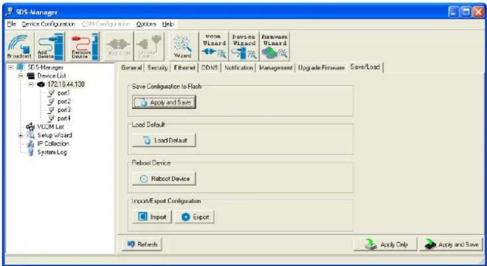
text_image
SDS-Manager File Device Configuration COM-Configuration Options Help Broadcast Add Devices Remove Device PC.COM Window Wizard VCOM Wizard Device Wizard Exware Wizard SDS-Manager Device List 172.16.44.130 port1 port2 port3 port4 VCOM List Setup Wizard IP Collection System Log General Security Ethernet CDNS Notification Management Upgrade Firmware Save/Load Save Configuration to Flash Apply and Save Load Default Load Default Reboot Device Reboot Device Import/Export Configuration Import Export Refresh Apply Only Apply and SaveFigure 5-11 Save / Load tab
The following table describes the labels in this screen.
| Label Description | |
| Save Configuration to Flash | Apply and Save to apply the selected config file and save current configuration into flash memory. |
| Load Default | Load default configuration except the network settings. If you want to load all factory defaults, press the “Reset” button on the device (Hardware restore). |
| Reboot Device Reboot the device server (warm start). | |
| Import Configuration | Restore the previous exported configuration. |
| Export Configuration | Export the current configuration to a file to backup the configuration. |
Table 5-6 Save / Load tab settings
5.1.2.3 Configure Serial Port
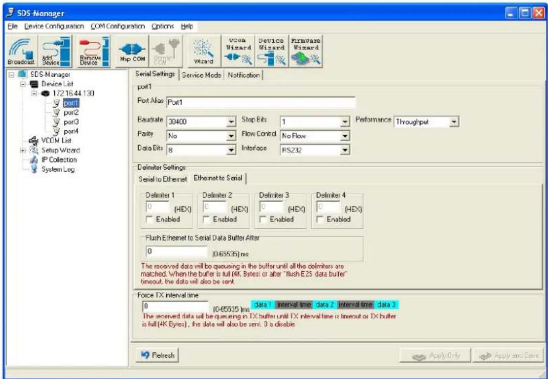
Serial Settings
text_image
SDS-Manager File Device Configuration COM Configuration Options Help Broadcast Add Device Remove Devices Map COM Wizard VCOM Wizard Devices Wizard Firmware Wizard SDS-Manager Device List 17216.44.130 port1 port2 port3 port4 VCOM List Setup Wizard IP Collection System Log Serial Settings Service Mode Notification port1 Port Alias Port1 Baudrate 39400 Stop Bits 1 Performance Throughput Purity No Flow Control No Flow Data Bits 8 Interface PS232 Delimiter Settings Serial to Ethernet Ethernet to Serial Delimiter 1 Delimiter 2 Delimiter 3 Delimiter 4 0 (HEX) 0 (HEX) 0 (HEX) 0 (HEX) Enabled Enabled Enabled Enabled Enabled Flush Ethernet to Serial Data Buffer After 0 (0.65535) ms The received data will be queuing in the buffer until all the delimiters are matched. When the buffer is full (4K Bytes) or after "flush E2S data buffer" timeout, the data will also be sent. Force TX interval time data 1 interval time data 2 interval time data 3 0 (0.65535) ms data 1 interval time data 2 interval time data 3 The received data will be queuing in TX buffer until TX interval time is timeout or TX buffer is full (4K Bytes), the data will also be sent. 0 is disable. Fletresh Apply Only Apply and SaveFigure 5-12 Serial Settings tab
The following table describes the labels in this screen.
| Label Description | |
| Port Alias | Text label on the port to describe the connected device. |
| Baudrate | 110bps/300bps/1200bps/2400bps/4800bps/9600bps/19200bps/38400bps/57600bps/115200bps/230400bps/460800bps |
| Stop Bits Select 1, 2, or | (1.5) stop bits. |
| Data Bits Select 5, 6, 7, | or 8 data bits. |
| Parity Select No, Even, | Odd, Mark, or Space parity. |
| Flow Control | Select No, XON/XOFF, RTS/CTS, or DTR/DSR Flow Control. |
| Interface | RS232 / RS422 / RS485(2-wires) / RS485(4-wires) |
| Performance | Throughput: This mode optimizes for highest transmission speed.Latency: This mode optimizes for shortest response time. |
| Serial to Ethernet | Delimiter: You can define a maximum of 4 delimiters (00~FF, Hex) for each communication direction. The data will be held until the delimiters are received or the option “Flush Serial to Ethernet data buffer” times out. 0 will disable this feature (factory default).Flush Data Buffer After: The received data will queue in the buffer until all thedelimiters are matched. When the buffer is full (4K Bytes) or after "flush S2E data buffer" timeout the data will also be sent. You can set the time from 0 to 65535 seconds. |
| Ethernet to Serial | Delimiter: You can define a maximum of 4 delimiters (00~FF, Hex) for each communication direction. The data will be hold until the delimiters are received or the option "Flush Ethernet to Serial data buffer" times out. 0 will disable this feature (factory default).Flush Data Buffer After: The received data will queue in the buffer until all the delimiters are matched. When the buffer is full (4K Bytes) or after "flushE2S data buffer" timeout the data will also be sent. You can set the time from 0 to 65535 seconds. |
| Force TX Interval Time | Force TX interval time is used to specify the timeout when no data has been transmitted. When the timeout is reached or the TX buffer is full (4K Bytes), the queued data will be sent. 0 means to disable. Factory default value is 0. |
Table 5-7 Serial settings
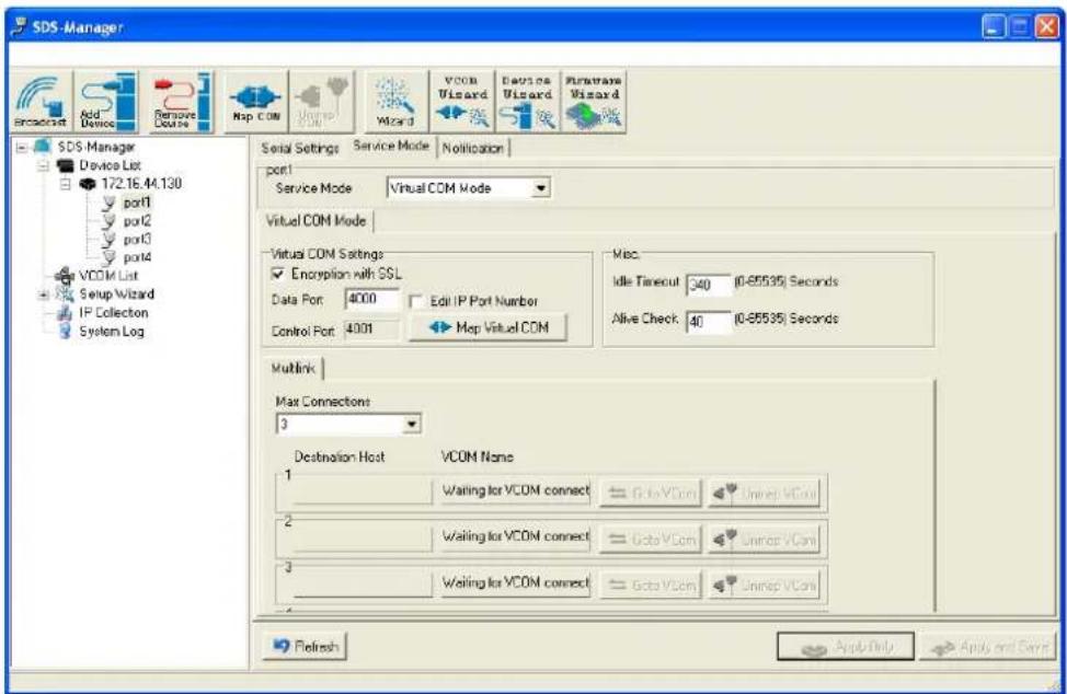
Service Mode – Virtual COM Mode
In Virtual COM Mode, the driver establishes a transparent connection between host and serial device by mapping the serial device server serial port to a local COM port on the host computer. Virtual COM Mode supports up to 5 simultaneous connections, so that multiple hosts can send or receive data via the same serial device at the same time.
text_image
SDS-Manager Add Device Remove Course Map COM Wizard Wizard VCOM Wizard Devices Wizard Hardware Wizard SDS Manager Device List 172.16.44.130 port1 port2 port3 port4 VCOM List Setup Wizard IP Collection System Log Serial Settings Service Mode Notification port Service Mode Virtual COM Mode Virtual COM Mode Virtual COM Settings Encryption with SSL Data Port 4000 Edit IP Port Number Control Port 4001 Map Virtual COM Misc. Idle Timeout 340 (0-65535) Seconds Alive Check 40 (0-65535) Seconds Multink Max Connections 3 Destination Host VCOM Name 1 Waiting for VCOM connect Goto VCom Unrep VCon 2 Waiting for VCOM connect Goto VCom Unrep VCon 3 Waiting for VCOM connect Goto VCon Unrep VCon Refresh Apply Help Apply and SaveFigure 5-13 Virtual COM mode
The following table describes the labels in this screen.
| Label Description | |
| Map Virtual COM | Click to select a Virtual COM Name to map on. |
| Max Connections | The maximum number of simultaneous connections is 5: the default value is 1. |
| Idle Timeout | When serial port stops data transmission for a defined period of time (Idle Timeout), the connection will be closed and the port can try to connect with other hosts. 0 disables this function (factory default). If Multilink is configured, only the first host connection is effective for this setting. |
| Alive Check | The serial device will send TCP alive-check package in each defined time interval (Alive Check) to remote host to check the TCP connection. If the TCP connection is not alive, the connection closes and the port is freed. 0 disables this feature (default). |
Table 5-8 Virtual COM
*Mapping Virtual COM ports is not available in the device web interface
Service Mode – TCP Server Mode
In TCP Server Mode, the device server is configured with a unique Port combination on a TCP/IP network. In this case, the device server waits passively to be contacted by the device. After a connection is established, it can then proceed with data transmission. TCP Server mode supports up to 5 simultaneous connections, so that multiple devices can receive data from the same serial device at the same time.

text_image
SDS-Manager File Device Configuration COM Configuration Options Help Broadcast Add Device Remove Device Nap COM Unmax Com Wizard vcom Wizard Device Wizard Firmware Wizard SDS-Manager Device List 172.16.44.130 port1 port2 port3 port4 VCOM List Setup Wizard IP Collection System Log Serial Settings Service Mode Notification port1 Service Mode TCP Server Mode TCP Server Mode TCP Server Settings Encryption with SSL Telnet Negotiation Data Port 10040 Auto Scan Control Port 10041 Misc Idc Timeout 340 (0.65535) Seconds Alive Check 40 (0.65535) Seconds Multilink Max Connections 1 Refresh Destination Host 1 Disconnect 2 Disconnect 3 Disconnect Refresh Apply Only Apply and SaveFigure 5-13 TCP Server mode
The following table describes the labels in this screen.
| Label Description | |
| TCP Server Settings | Encryption with SSL: TCP Server uses Secure Socket Layer encryption.Telnet Negotiation: TCP Server uses Telnet Negotiation protocol encryption. |
| Data Port Set the port number for data transmission. | |
| Auto Scan | Scan the data port automatically. |
| Idle Timeout | When serial port stops data transmission for a defined period of time (Idle Timeout), the connection will be closed and the port will be freed and try to connect with other hosts.A value of 0 disables this function. The factory default value is 0. If Multilink is configured, only the first host connection is effective for this setting. |
| Alive Check | The serial device will send TCP alive-check package in each defined time interval (Alive Check) to remote host to check the TCP connection. If the TCP connection is not alive, the connection will be closed and the port will be freed. 0 disables this function. The factory default is 0. |
| Max Connection | The SDS supports up to 5 simultaneous connections; the default value is 1. |
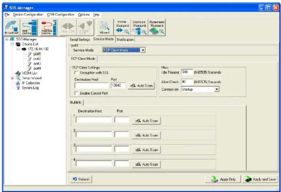
Service Mode – TCP Client Mode
In TCP Client Mode, the device can establish a TCP connection with a server by the method you have selected (Startup or Any Character). After the data has been transferred, device can disconnect automatically from the server by using the TCP alive check time or Idle time settings.
text_image
SDS-Manager File Device Configuration COM Configuration Options Help Broadcast Red Red Dewers Red/Sat Dewers Blue Vccs Only Vccs Wizard Vccs Wizard Device Wizard Puraware Wizard SDS-Manager Device List 172.16.44.130 port1 port2 port3 port4 VCOM List Setup Wizard IP Collection System Log Serial Settings Service Mode Notification port1 Service Mode TCP Client Mode TCP Client Mode TCP Client Settings Encryption with SSL Destination Host Port 10040 Auto Scan Enable Control Port Misc Idle Timeout: 340 (0-65535) Seconds Alive Check 40 (0-65535) Seconds Connect on Startup Multink: Destination Host Port 1 Auto Scan 2 Auto Scan 3 Auto Scan 4 Auto Scan Refresh Apply Only Apply and SaveFigure 5-14 TCP Client mode
The following table describes the labels in this screen.
| Label Description | |
| Destination Host | Set the IP address of host. |
| Port Set the port number of data port. | |
| Idle Timeout | When serial port stops data transmission for a defined period of time (Idle Timeout), the connection will be closed and the port is freed to try to connect with other hosts. A value of 0 disables this function (factory default). If Multilink is configured, only the first host connection is effective for this setting. |
| Alive Check | The serial device will send TCP alive-check package in each defined time interval (Alive Check) to remote host to check the TCP connection. If the TCP connection is not alive, the connection will be closed and the port will be freed. A value of 0 disables this function (factory default). |
| Connect on Startup | The TCP Client will build TCP connection once the connected serial device is started. |
| Connect on Any Character | The TCP Client will build TCP connection once the connected serial device starts to send data. |
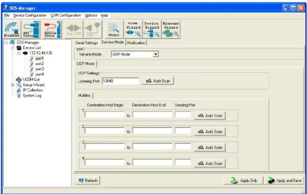
Service Mode – UDP Mode
Compared to TCP communication, UDP is faster and more efficient. In UDP mode, you can Uni-cast or Multi-cast data from the serial device server to host computers, and the serial device can also receive data from one host or from multiple hosts.
text_image
SDS-Manager File Device Configuration COM Configuration Options Help Broadcast Add Devise Remove Devise Map COM Award Wizard vcom Wizard Devices Wizard Firmware Wizard SDS Manager Device List 172.16.44.130 port1 port2 port3 port4 VCOM List Setup Wizard IP Collection System Log Serial Settings Service Mode Notification port1 Service Mode UDP Mode UDP Mode UDP Settings Listening Port 10040 Auto Scan Multink Destination Host Begin Destination Host End Sending Port to Auto Scan to Auto Scan tc Auto Scan tc Auto Scan Refresh Apply Only Apply and SaveFigure 5-15 UDP mode
| Label Description | |
| Listening Port | The UDP listening port (e.g., port number 10040). |
| Auto Scan | Click to automatically scan for a UDP listening port. |
| Destination Host Begin | Enter a beginning IP address for the destination host address. |
| Destination Host End | Enter an ending IP address for the destination host address. |
| Sending port Enter the sending port number. | |
Notification
Specify the events to be noticed and select the method (E-mail, SNMP trap, System log).

text_image
SDS-Manager File Device Configuration COM Configuration Options Help Broadcast Add Device Remove Device Map Com Unmiss COM Wizard VCOM Wizard Device Wizard Firmware Wizard SDS-Manager Device List 172.16.44.130 por1 por2 por3 por4 VCOM List Setup Wizard IP Collection System Log Serial Settings Service Mode Notification SNMP Trap Email Notification Syslog Notification SNMP Settings Email Settings Syslog Settings Notified Items DCD Changed CTS Changed DSR Changed Port Connected RI Changed Port Disconnected Trap Server1 Trap Server2 Trap Server3 Trap Server4 Refresh Apply Only Apply and SaveFigure 5-16 Notification
The following table describes the labels in this screen.
| Label Description | |
| DCD Changed | When DCD (Data Carrier Detect) signal changes, it indicates that the modem connection status has changed. Notification will be sent. |
| DSR Changed | When DSR (Data Set Ready) signal changes, it indicates that the data communication equipment is powered off. A Notification will be sent. |
| RI Changed | When RI (Ring Indicator) signal changes, it indicates that the incoming of a call.A Notification will be sent. |
| CTS Changed | When CTS (Clear To Send) signal changes, it indicates that the transmission between computer and DCE can proceed. A notification will be sent. |
| Port Connected | In TCP Server Mode, when the device accepts an incoming TCP connection, this event will trigger. In TCP Client Mode, when the device has connected to the remote host, this event will trigger. In Virtual COM Mode, Virtual COM is ready to use. A notification is sent. |
| Port Disconnected | In TCP Server/Client Mode, if the device loses the TCP link, this event will trigger. In Virtual COM Mode, when Virtual COM is not available, this event will trigger. A notification will be sent. |
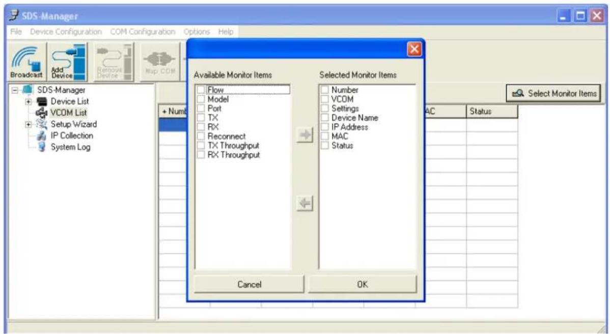
5.1.2.4 VCOM List
At the VCOM List, click the Select Monitor Items button to display the Available and Selected Monitor Items.
text_image
SDS-Manager File Device Configuration COM Configuration Options Help Broadcast Add Device Remove Device Map CDM SDS-Manager Device List VCOM List Setup Wizard IP Collection System Log Available Monitor Items Flow Model Port TX RX Reconnect TX Throughput RX Throughput Selected Monitor Items Number VCOM Settings Device Name IP Address MAC Status Cancel OK Select Monitor Items AC Status| Label Description | |
| Available Monitor Items | Check one or more items for selection. Use the green right arrow ➔ button to move a selected item to the “Available Monitor Items” column. |
| Selected Monitor Items | Check one or more items for selection. Use the red left arrow ← button to move a selected item to the “Available Monitor Items” column. |
| Cancel | Click to cancel any changes. |
| OK | Click to OK any changes. |
5.1.2.5 Setup Wizard
The Setup Wizard provides links to the Virtual COM Wizard, Serial Tunnel Wizard, Group IP Wizard, Group Setup Wizard, and Group Firmware Wizard.

text_image
SDS-Manager File Device Configuration COM Configuration Options Help Broadcast Add Device Remove Device Vac COM Unmap COM Wizard vcom Wizard Device Wizard Firmware Wizard SDS-Manager Device List 172.16.44.130 172.16.44.131 172.16.44.132 port1 172.16.47.156 port1 VCOM List Setup Wizard Virtual COM Wizard Serial Tunnel Wizard Group IP Wizard Group Setup Wizard Group Firmware Wizard IP Collection System Log Welcome to Wizard Center Please select a wizard you need Virtual COM Wizard Serial Tunnel Wizard Group IP Wizard Group Setup Wizard Group Firmware WizardVirtual COM Wizard lets you set up the device serial port and map it to Virtual COM port.
STEP 1. Select serial port(s) from available devices.
STEP 2. Setup serial ports configuration, baudrate, data bits...etc.
STEP 3. Select the Virtual COM naming.
STEP 4. Done.
Serial Tunnel Wizard helps you couple two serial devices to directly communicate by Ethernet without the PC.
STEP 1. Select two devices that should be tunneled together
STEP 2. Select serial parameters such as baud rate, data bits.
STEP 3. Finish.
Group IP Wizard helps you configure the IP addresses of a group of new devices. The devices already in the configuration list will not be included.
STEP 1. Locate the new devices by broadcast or by IP range.
STEP 2. Configure the IP range or DHCP IP.
STEP 3. Start
Group Setup Wizard helps you to copy one device settings to the other same models. If the listbox is empty, then no devices were located. Please search and add the devices again.
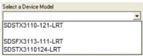
text_image
Select a Device Model SDSTX3110-121-LRT SDSFX3113-111-LRT SDSTX3110124-LRTSTEP 1. Select the device model.
STEP 2. Select the source device and destination devices.
STEP 3. Select the device and port settings to copy
STEP 4. Start copying
Group Firmware Wizard helps you to update firmware for a group of devices.
STEP 1. Select the device model.
STEP 2. Select the target devices.
STEP 3. Select the new firmware.
STEP 4. Go.
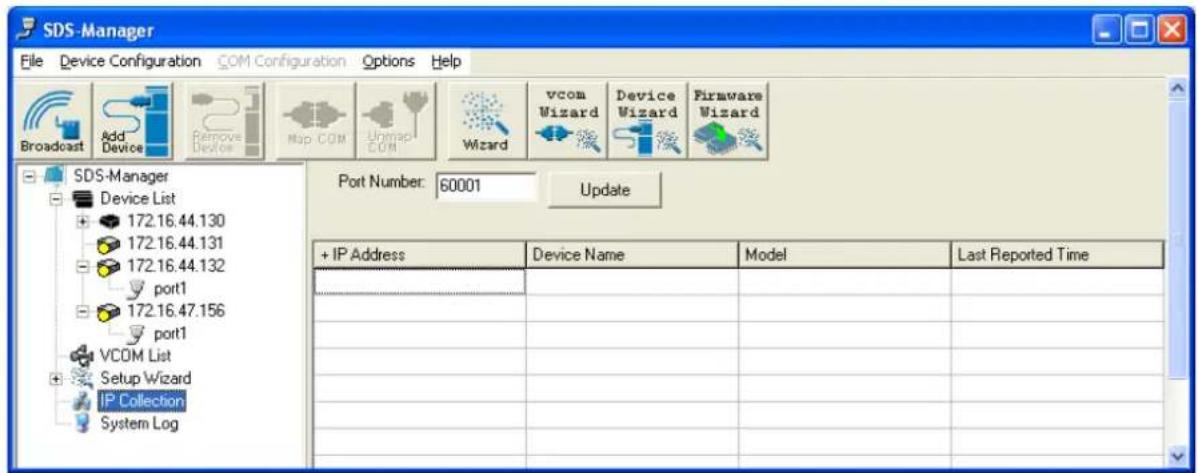
5.1.2.6 IP Collection
text_image
SDS-Manager File Device Configuration COM Configuration Options Help Broadcast Add Device Remove Device Map COM Umap COM Wizard vcom Wizard Device Wizard Firmware Wizard SDS-Manager Device List 172.16.44.130 172.16.44.131 172.16.44.132 port1 172.16.47.156 port1 VCOM List Setup Wizard IP Collection System Log Port Number: 60001 Update + IP Address Device Name Model Last Reported Time _______________________________ _______________________________ _______________________________ _______________________________ _______________________________ _______________________________ _______________________________ _______________________________ _______________________________ _______________________________| Label Description | |
| Port Number | The IP collection port number (e.g., port number 60001. |
| Update | Button to update the information display. |
| IP Address | The reported IP address. |
| Device Name | The reported device's name. |
| Model | The reported model. |
| Last Reported Time | The day, date and time of the last report. |
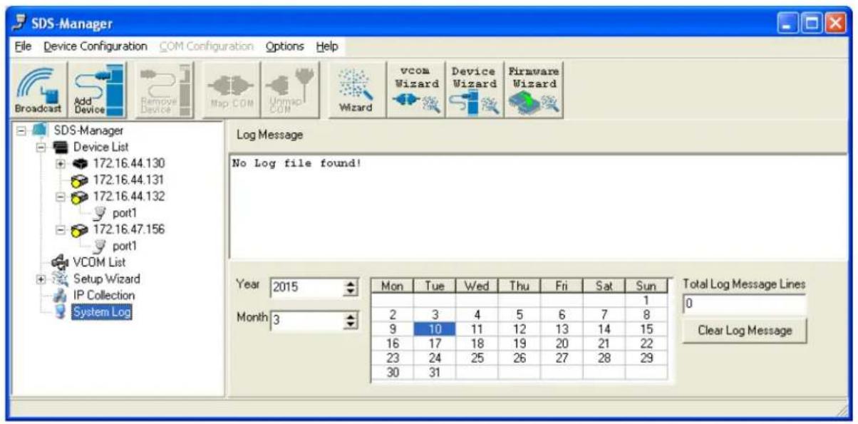
5.1.2.7 System Log
Displays log messages if any are found.
text_image
SDS-Manager File Device Configuration COM Configuration Options Help Broadcast Add Device Remove Device Map COM Unmap COM Wizard vcom Wizard Device Wizard Firmware Wizard SDS-Manager Device List 172.16.44.130 172.16.44.131 172.16.44.132 port1 172.16.47.156 port1 VCOM List Setup Wizard IP Collection System Log Log Message No Log file found! Year 2015 Mon Tue Wed Thu Fri Sat Sun Month 3 2 3 4 5 6 7 8 9 10 11 12 13 14 15 16 17 18 19 20 21 22 23 24 25 26 27 28 29 30 31 Total Log Message Lines 0 Clear Log Message| Label Description | |
| Log Message | The related log file message. Displays 'No Log file found' if none reported.Double-click an instance to display event specifics. |
| Year Select the year. | |
| Month Select the month. | |
| Day Select the day (Mon - Sun). | |
| Total Message Lines | Displays the number of lines currently shown. |
| Clear Log Message Click to clear the log messages displayed. | |
5.1.2.8 Top Bar Icons - Remove Device
Clicking the Remove Device icon lets you delete an added (existing) device from the device list.
text_image
SDS-Manager File Device Configuration COM Configuration Options Help Broadcast Add Device Remove Device Msp COM Unmap COM Wizard vcom Wizard Device Wizard Firmware Wizard SDS-Manager Device List VCOM List Setup Wizard IP Collection System Log SDS-Manager5.1.2.9 Map COM
Clicking the Map COM icon lets you map an existing COM port.
5.1.2.10 Unmap COM
Clicking the Unmap COM icon lets you unmap an existing mapped COM port.
5.1.2.11 Wizard
Clicking the Wizard icon displays the Welcome to Wizard Center where you can select the various Wizards. See the related section.

5.1.2.12 vcom Wizard
Clicking the vcom Wizard icon displays the Virtual COM Wizard; see the related section.

5.1.2.13 Device Wizard
Clicking the Device Wizard icon displays the Group Setup Wizard; see the related section.

5.1.2.14 Firmware Wizard
Clicking the Firmware Wizard icon displays the Group Firmware Wizard; see the related section.
5.1.2.15 Top Bar Dropdown Menu Items
The Top Bar (drop down) menu items provide a set of functions similar to the left pane menu items.
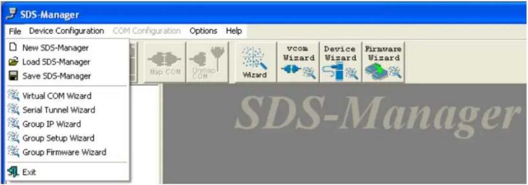
File options
The options presented here include New/Load/Save SDS-Manager configs, Wizards for Virtual COM, Serial Tunnel, Group IP/Setup/Firmware, and Exit.
text_image
SDS-Manager File Device Configuration COM Configuration Options Help New SDS-Manager Load SDS-Manager Save SDS-Manager Virtual COM Wizard Serial Tunnel Wizard Group IP Wizard Group Setup Wizard Group Firmware Wizard ExitDevice Configuration options
These options include Broadcast Search, Add Device by IP, Remove Device, and Import/Export Device Configuration functions.

text_image
SDS-Manager File Device Configuration COM Configuration Options Help Broadcast Search Add Device by IP Remove Device Import Device Configuration Export Device Configuration Setup Wizard IP Collection vcom Wizard Device Wizard Firmware Wizard SDS-ManagerOptions > Network Bandwidth options
Here you can select from four network BW categories: 1. Intranet, T1 or faster. 2. Internet, ADSL or cable modem. 3. Modem, wireless or lower. 4. 3G, ping time > 3 seconds.

text_image
SDS-Manager File Device Configuration COM Configuration Options Help Network Bandwidth Intranet, T1 or faster Internet, ADSL or cable modem Modem, wireless or lower 3G, ping time > 3 seconds Broadcast Add Device Remove Device Map COM Unmap COM Wizard SDS-Manager Device List VCOM List Setup WizardHelp > Help option
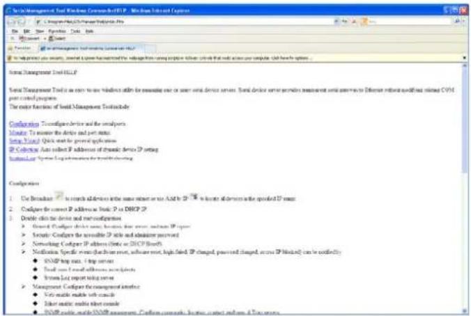
The Help > Help Options menu provides the Serial Management Tool HELP in several categories.
text_image
Visual Management Tool Windows Common-Net HSP - Windows Internet Explorer File Edit View Options Tools Help Microsoft Word Functions To help print your server, install a new instance in the setup from managing the server to access your computer. Add how to options: Visual Management Tool HSP Visual Management Tool is an active window within the serverless one or two serial device servers. Serial device server provides maintenance and service via different network configurations (CVM) and control programs. The order function of Social Management Tool includes: Configuration: To configure device and the system. Monitor: To monitor the device and port status. System Type: Quick start by general applications. IP Connection: Auto link IP address of dynamic device IP setting. Internal/Local System Log performance for network routing. Configuration: 1. Use Breakthrough to search additional devices into some relevant sites as And it is IP 78. To locate additional devices with specified IP zones. 2. Configure the current IP address at local P to DHCP IP. 3. Double click the device and net configuration: - Default Configur device must be found that server, network, and server IP types - Security Configur the available IP site and administrator retained - Networking Configur IP address (Note or DHCP Network) - Notification Specific events (fraction key, software reset, high-fired IP changed, pushed and changed, access IP Method) can be conflicting - SNMP log rate, I log rate - Small user email with additional certificate - Linux List report testing server - Management Configur for management interface - Web music audio file contains - User music audio file contains - SNMP audio files (SNMP assessment). Confirm community business contact information & Services.Help > Help About option
This menu option displays version, build, and copyright information.
text_image
About SDS-Manager Version 1.0 (Build Feb32015112758) Copyright 2015 TRANSITION Co., Ltd. OKExit the SDS-Manager
If you right-click the SDS-Manager icon in the Windows icon tray and select Exit, the Quit dialog displays with the message "Keep the virtual COM running?".
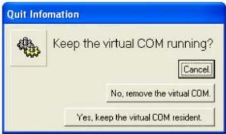
text_image
Quit Information Keep the virtual COM running? Cancel No, remove the virtual COM. Yes, keep the virtual COM resident.The options here are:
Cancel: cancel the exit attempt and return to the SDS-Manager.
No, remove the virtual COM.: quit the SDS-Manager and remove the configured virtual COM.
Yes, keep the virtual COM resident.: quit the SDS-Manager and keep the configured virtual COM resident.
5.2 Configuration by Web Browser
The SDS-Manager lets you configure the System, Port Serial Setting, Management, and Reset / Restore / Backup / Upgrade / Reboot functions.
5.2.1 CONNECT TO THE WEB PAGE
- Input the Device Server IP address "https://192.168.1.77" in the Internet Explorer Address input box.
- Click "Yes" button on the dialog box.
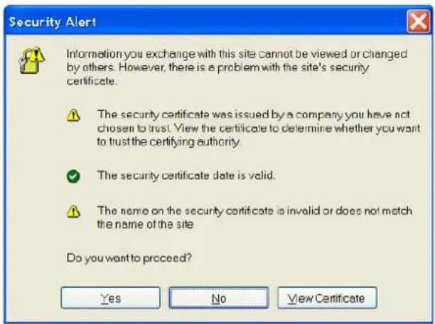
text_image
Security Alert Information you exchange with this site cannot be viewed or changed by others. However, there is a problem with the site's security certificate. The security certificate was issued by a company you have not chosen to trust. View the certificate to determine whether you want to trust the certifying authority. The security certificate date is valid. The name on the security certificate is invalid or does not match the name of the site Do you want to proceed? Yes No View Certificate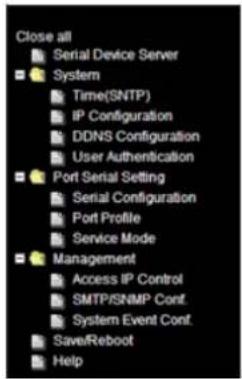
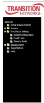
text_image
Close all Serial Device Server System Time(SNTP) IP Configuration DDNS Configuration User Authentication Port Serial Setting Serial Configuration Port Profile Service Mode Management Access IP Control SMTP/SNMP Conf. System Event Conf. Save/Reboot Help- Input the name (admin) and password (admin) (only if password is set), then click "OK".

text_image
Connect to 192.168.1.77 cgi-bin User name: root Password: ••••• Remember my password OK CancelTransition Networks
-
Enter the IP Address and MAC Address for the device at the System Information page.
-
Navigate to the System > Time(SNTP) menu to configure SNTP and Telnet Console access at the SNTP Configuration page. Click the Apply button when done.
Name: DeviceServer-DEFAULT
SNTP: Enable or Disable SNTP globally. The default is Disable.
Time Zone: e.g., (GMT-12:00)Eniwetok, (GMT-06:00)Central Time (US & Canada) or (GMT+08:00)Taipei.
Local Time: e.g., Fri Feb 6 07:59:18 CST 2015.
Time Server: e.g., pool.ntp.org.
Port: e.g., commonly used port number 123.
Telnet Console: select Enable or Disable for the Console access. The default is telnet access Enabled.
- Navigate to System > IP Configuration to configure IP and Ethernet mode parameters. Click Apply when done.
IP Configuration: At the dropdown, select Static, DHCP/BOOTP, or PPPoE. The default is Static.
Using Static IP allows manually assigning an IP address.
Using DHCP/BOOTP an IP Address is automatically assigned by a DHCP server in your network.
Using PPPoE allows Point-to-Point Protocol over Ethernet as the network protocol for encapsulating PPP frames inside Ethernet
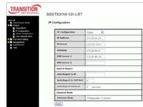
text_image
TRANSITION NETWORKS SD5TX3110-121-LRT IP Configuration SP Configuration 31001 SP Address 172.16.44.129 Netreach 268.886.250.9 Gateway 172.16.44.22 DNS Server 1 172.16.44.155 DNS Server 2 Auto IP Report AutoReport to SP AutoReport to TCP Port Auto-Report Internet: Second Ethernet Mode Ethernet Mode: Redundant Switch Helpframes. The "PPPoE Setting" page displays with "User Name" and "Password" entry fields, a read-only "Status" field, Connect and Disconnect buttons, and the Return button.
You must assign a valid IP address for the serial device server before attaching to your network. Your network administrator should provide you the IP address and related settings. The IP address must be unique within the network (otherwise, DS will not have a valid connection to the network). The factory default IP address is "192.168.1.77"
SDSFX311x-111-LRT User Guide

text_image
TRANSITION NETWORKS. SDSTX3110-121-LRT System Information open all Serial Device Server System Port Serial Setting Management Save/Reflow Help IP Address: 172.16.44.129 MAC Address: 00:1E'04-01 SB-08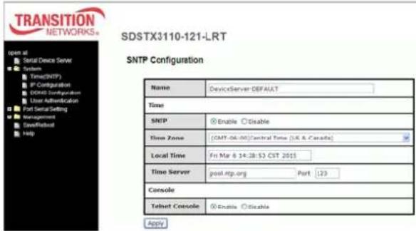
text_image
TRANSITION NETWORKS SDSTX3110-121-LRT SNTP Configuration Name DeviceServer DEFAULT Time SNTP Enable Disable Time Zone [CMT-06.00][Central Time (UK & Canada)] Local Time Fin Mar 8 14:28:53 CST 2015 Time Server posl.ntg.org Port 123 Console Telnet Console Enable Disable ApplyNetmask: e.g., 255.255.252.0. All devices on the network must have the same subnet mask to communicate on the network.
Gateway: Assign the IP address of the gateway
DNS Server 1: Enter the IP address of the DNS server; The DNS server translates domain names into IP addresses.
DNS Server 2: Enter a DNS Server address for a second DNS server or leave blank.
Auto Report to IP: enter an IP address for the auto IP reporting.
Auto Report to TCP Port: enter a TCP port for auto reporting to this TCP port.
Auto Report Interval: the time interval between reports in seconds. The default is 0 seconds. The device server will report its status periodically.
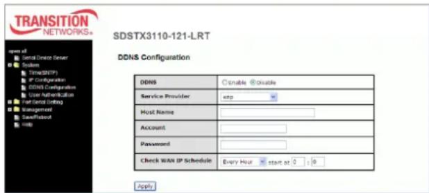
- For DDNS (Dynamic DNS) configuration, navigate to the System >DDNS Configuration menu and
configure the related parameters. Click the
Apply button when done.
DDNS: select Enable or Disable DDNS on a global basis (at the system level). The default is Disabled.
Service Provider: at the dropdown select ezip, pgpow, dhs, constanttime, dyndns, dyndns-static, dyndns-custom, ods, tzo, easydns, easydns-partner, gnudip, justlinux, dyns, hn, zoneedit, heipv6tb, or 3322.
text_image
TRANSITION NETWORKS* SDSTX3110-121-LRT DDNS Configuration DDNS Enable Enable Service Provider: snp Host Name: Account: Password: Check WAN IP Schedule Every Hour start at 0 : 8 ApplyHost Name: Sets the DDNS host device name
Account: Sets the login name for the DDNS service
Password: Sets the login password for the DDNS service
Check WAN IP Schedule: at the dropdown select every hour, day, week or month and select the start time in hours and minutes.
- Configure User Authentication via the the System > User Authentication menu. Enter the User Name, old password, enter and confirm the new password, and then click the Apply button.

text_image
TRANSITION NETWORKS* open at Serial Device Server System Time(SMTP) IP Configuration DCMS Configuration User Authentication Port Serial Setting Management Save/Reboot Help SDSFX3113-111-LRT User Authentication User Name root Old Password New Password Confirm New Password Apply- Navigate to the Port Serial Setting > Serial Configuration menu and configure the related parameters. Click the Apply button when done.
Port: At the Port dropdown, select Port 1, 2, 3, or 4.
Port Alias: e.g., Port1.
Interface: At the dropdown, select RS232, RS422, RS485(2-wires), or RS485(4-wires). The default is RS232.
Baud Rate: At the dropdown, select 110, 300, 1200, 2400, 4800, 9600, 19200, 38400, 57600, 115200, 230400, or 460800 bps baud rate. The default is 38,400 bps.
text_image
TRANSITION NETWORKS+ open all Serial Device Server System Port Serial Setting Serial Configuration Port Profile Service Mode Management Networkbot HDDSDSTX3110-124-LRT
Serial Configuration
| Port1 | |
| Port Alias | Port1 |
| Interface | Rs2.32 |
| Band Rate | 38400 |
| Data Bits | 0 |
| Stop Bits | 1 |
| Parity | none |
| Flow Control | none |
| Force TX Interval Time | 0 ms |
| Performance | Throughput Latency |
Data Bits: At the dropdown, select 8, 7, 6, or 5 data bits.
Stop Bits: At the dropdown, select 1 or 2(1.5) stop bits.
Parity: At the dropdown, select None, Odd, Even, Mark, or Space parity.
Flow Control: At the dropdown, select None, XON/XOFF, RTS/CTS, or DTR/DSR.
Force TX Interval Time: use to specify the timeout when no data has been transmitted. When the timeout is reached or TX buffer is full (4K Bytes), the queued data will be sent. An entry of 0 disables this function. The factory default value is 0.
Performance: click the radio button for either Throughput or Latency mode, where:
Throughput mode is optimized for highest transmission speed.
Latency mode is optimized for shortest response time.
- Navigate to the Port Serial Setting > Port Profile menu and configure the related parameters.
Click the Apply button when done.
Port: At the Port dropdown, select Port 1, 2, 3, or 4.
Local TCP Port: enter the port number of the local TCP port (e.g., port 4000).
Mode: the current mode (Serial to Ethernet or Ethernet to Serial).

SDSTX3110-124-LRT
Port Profile
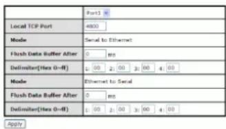
text_image
Port1 Local TCP Port 4900 Mode Serial to Ethernet Flush Data Buffer After 0 mm Delimiter(Max 0-#) 1:00 2:00 3:00 4:00 Mode Ethernet to Serial Flush Data Buffer After 0 mm Delimiter(Max 0-#) 1:00 2:00 3:00 4:00 ApplyFlush Data Buffer After: the meaning depends on the 'Mode' setting above:
If Mode is Serial to Ethernet, the received data is queued in the buffer until all the delimiters are matched. When the buffer is full (4K Bytes) or after "flush S2E data buffer" timeout, the data is also sent. Set the time from 0 - 65535 seconds.
If Mode is Ethernet to Serial, the received data is queued in the buffer until all the delimiters are matched. When the buffer is full (4K Bytes) or after "flush E2S data buffer" timeout, the data will also be sent. Set the time from 0 - 65535 seconds.
Delimiter(Hex 0\~ff): the meaning depends on the 'Mode' setting above:
If 'Mode' is Serial to Ethernet, you can define up to four delimiters (00\~FF, Hex) for each. The data is held until the delimiters are received or the option "Flush Serial to Ethernet data buffer" times out. A 0 entry disables this function (factory default value).
If 'Mode' is Ethernet to Serial, you can define upt to four delimiters (00\~FF, Hex) for each. The data is held until the delimiters are received or the option "Flush Ethernet to Serial data buffer" times out. A 0 entry disables this function (factory default setting).
- Navigate to the Port Serial Setting > Service Mode menu and configure the related parameters. Click the Apply button when done. The parameters are described below.
Data Encryption: enable or disable data encryption globally. The default is Disabled.
Service Mode: At the dropdown, select Virtual COM Mode, TCP Server Mode, TCP Client Mode, or UDP Mode. Click the Apply button when done. The parameter descriptions are below:
In Virtual COM Mode, the driver establishes a transparent connection between host and serial device by mapping the Port of the serial server serial port to local COM port on the host computer. Virtual COM Mode also supports up to five simultaneous connections, so that multiple hosts can send or receive data by the same serial device at the same time.
In TCP Server Mode, DS is configured with a unique Port combination on a TCP/IP network. In this case, DS waits passively to be contacted by the device. After the device establishes a connection with the serial device, it can then proceed with data transmission. TCP Server mode also supports up to five simultaneous connections, so that multiple device can receive data from the same serial device at the same time.
In TCP Client Mode, the device can establish a TCP connection with a server by the method you set (Startup or Any Character). After the data is transferred, the device can disconnect automatically from the server by using the TCP Alive Check time or Idle timeout settings.
In UDP Mode, you can Uni-cast or Multi-cast data from the serial device server to host computers, and the serial device can also receive data from one or multiple host. Compared to TCP communication, UDP is faster and more efficient.
Telnet Negotiation: Displays only if 'Data Encryption' is Disabled (see above). The default is Disabled.
Destination Host: Displays only in 'TCP Client Mode' and if 'Data Encryption' is Disabled (see above).
Destination Port: e.g., 65535. Displays only in 'TCP Client Mode' and if 'Data Encryption' is Disabled (see above).
Transition Networks
SDSFX311x-111-LRT User Guide
Idle Timeout: when serial port stops data transmission for a defined period of time (Idle Timeout), the connection will be closed and the port will be freed and try to connect with other hosts. The valid range is 0-65535 seconds. An entry of 0 disables this feature (factory default value). If Multilink is configured, only the first host connection is effective for this setting.
Alive Check: the serial device will send TCP alive-check package in each defined time interval (Alive Check) to remote host to check the TCP connection. If the TCP connection is not alive, the connection will be closed and the port will be freed. The valid range is 0-65535 seconds. An entry of 0 disables this feature (factory default value). The factory default is 0.
Connect on: check the Startup or Any Character radio button. The parameters are:
Connect on Startup: the TCP Client will build TCP connection once the connected serial device is started.
Connect on Any Character: the TCP Client will build TCP connection once the connected serial device starts to send data.
Max Connection: up to five simultaneous connections are supported; the default value is 1 connection.
Service Mode Sample Screens
Service Mode = Virtual COM Mode
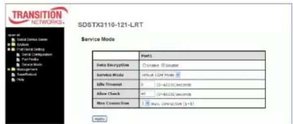
text_image
TRANSITION NETWORKS+ SDSTX3110-121-LRT Service Mode Data Encryption Disable Disable Service Mode Virtual COM Mode Idle Time (0~45530)seconds Allow Check (0~45530)seconds Max Connection was connection (1~5) ApplyService Mode = TCP Server Mode
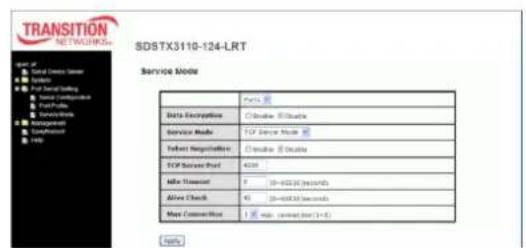
text_image
TRANSITION NETWORKS SDSTX3110-124-LRT Service Mode Data Encryption Enable Enable Service Mode TCP Server Mode User Registration Enable Enable Active Request 7 (0-600.00 seconds) Active Check 45 (0-600.00 seconds) Max Connection 1 Max connection port (1+8) NoteService Mode = TCP Client Mode
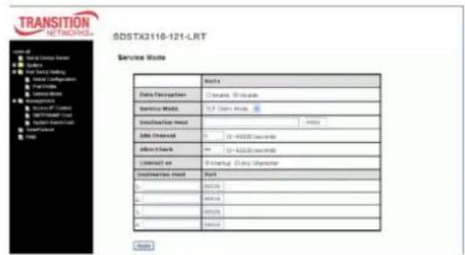
text_image
TRANSITION NETWORKS SDSTX3110-121-LRT Service Route Data Description: Cramark 800000 Service Mode: TCP User Mode Destination mode: Sub Command: 10 - 400000 Command Off Track: 10 - 400000 Off Track Connection to: B Startup (Any Identifier) Destination mode: Port 1. 96500 2. 96500 3. 96500 4. 96500 Browse Browse Browse BrowseService Mode = UDP Mode
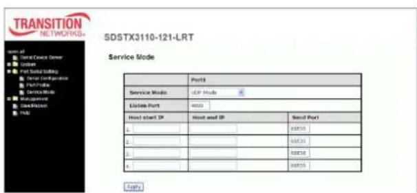
text_image
TRANSITION NETWORKS- SDSTX3110-121-LRT Service Mode Port1 Service Mode: UCP Mode License Port: 4000 Host start IP: Host and IP Send Port 1: 68555 2: 68555 3: 68555 4: 68555- Navigate to the Management > Access IP Control menu and configure the related parameters.
The Access IP Control settings let you add or block the remote host IP addresses to prevent unauthorized access. If a host's IP address is in the accessible IP table, then the host will be allowed to access the device server. You can control device server access by setting the parameter.
a) Only one host with a special IP address can access the device server, "IP address /255.255.255.255" (e.g., "192.168.0.1/255.255.255.255").
b) Hosts on a specific subnet can access the device server. "IP address/255.255.255.0" (e.g., "192.168.0.2/255.255.255.0").
c) Any host can access the device server. Disable this function by un-checking the "Enable IP Filter" checkbox.
Access IP Control List

The parameters are described below.
Enable IP Filtering: Not checking this option will allow any IP to have assessibility.
No.: column with lines for instances 1-16.
Activate the IP: check the checkbox to activate this IP.
IP Address: entry box for the IP address for the entity.
Netmask: entry box for the IP address for the entity (e.g., 255.255.252.0).
Click the Apply button when done.
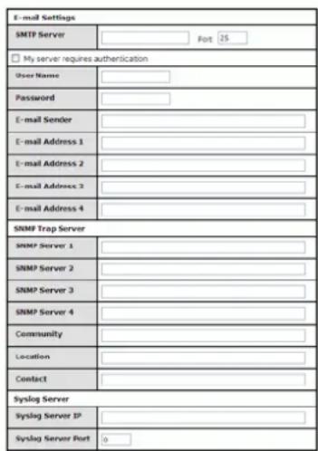
- Navigate to the Management > SMTP/SNMP Conf menu and configure the related parameters. Here you can configure E-Mail Settings, server authentication, SNMP Trap Servers and Syslog Server parameters as described below.
SMTP Server configuration includes the mail server's IP address or domain. If the authentication is required, specify your Username and Password. You can specify up to four Email addresses to receive the notification.
SNMP Server configuration includes the SNMP Trap

text_image
oper at □ Sera Devices Server □ System □ Port SerialSetting □ Management □ AccessIP Control □ CMTS/IMP Control □ System/Boost Control □ SaveRebell □ HelpSMTP/SNMP Configuration
text_image
E-mail Settings SMTP Server #pt 25 My server requires authentication User Name: Password: E-mail Sender: E-mail Address 1: E-mail Address 2: E-mail Address 3: E-mail Address 4: SNMP Trap Server SNMP Server 1: SNMP Server 2: SNMP Server 3: SNMP Server 4: Community: Location: Contact: Syslog Server Syslog Server IP: Syslog Server Port: 0Apply
Server IP address, Community, Location and Contact. There are 4 SNMP addresses you can specify to receive the notification.
SysLog Server configuration includes the server IP and server Port. This option must be used with SDS-Manager.
Click the Apply button when done.
- Navigate to the Management > System Event Conf menu and configure the Device Event Notification and Port Event Notification parameters.
Hardware Reset (Cold Start) refers to starting the system from power off (contrast this with warm start). When performing a cold start, DS will automatically issue an Auto warning message by sending E-mail, log information or an SNMP trap after booting.
Software Reset (Warm Start) refers to restart the computer without turning the power off. When performing a warm start, DS will automatically send an E-mail, log information or SNMP trap after reboot.
Login Failed: when an unauthorized access from the Console or Web interface, a notification will be sent.
System Event Configuration
| Device Event Notification | |||
| Hardware Reset (Cold Start) | ☐SMTP Mail | ☐SNMP Trap | ☐Syslog |
| Software Reset (Warm Start) | ☐SMTP Mail | ☐SNMP Trap | ☐Syslog |
| Login Failed | ☐SMTP Mail | ☐SNMP Trap | ☐Syslog |
| IP Address Changed | ☐SMTP Mail | ☐SNMP Trap | ☐Syslog |
| Password Changed | ☐SMTP Mail | ☐SNMP Trap | ☐Syslog |
| Access IP Blocked | ☐SMTP Mail | ☐SNMP Trap | ☐Syslog |
| Redundant Power Changed | ☐SMTP Mail | ☐SNMP Trap | ☐Syslog |
| Redundant Ethernet Changed | ☐SMTP Mail | ☐SNMP Trap | ☐Syslog |
| Port Event Notification | |||
| DCD Changed | ☐SMTP Mail | ☐SNMP Trap | ☐Syslog |
| DSR Changed | ☐SMTP Mail | ☐SNMP Trap | ☐Syslog |
| RI Changed | ☐SMTP Mail | ☐SNMP Trap | ☐Syslog |
| CTS Changed | ☐SMTP Mail | ☐SNMP Trap | ☐Syslog |
| Port Connected | ☐SMTP Mail | ☐SNMP Trap | ☐Syslog |
| Port Disconnected | ☐SMTP Mail | ☐SNMP Trap | ☐Syslog |
Apply
IP Address Changed: when IP address of device changes, a notification will be sent.
Password Changed: when password of device changes, a notification will be sent.
Access IP Blocked: when the host accesses the device with blocked IP addresses, a notification will be sent.
Redundant Power Change: when status of power changed, a notification will be sent.
Redundant Ethernet Change: when the status of an Ethernet port changes, a notification will be sent.
DCD changed: when DCD (Data Carrier Detect) signal changes, it indicates that the modem connection status has been changed. A Notification will be sent.
DSR changed: when DSR (Data Set Ready) signal changes, it indicates that the data communication equipment is powered off. A Notification will be sent.
RI changed: when RI (Ring Indicator) signal changes, it indicates an incoming call. Notification will be sent.
CTS changed: when CTS (Clear To Send) signal changes, it indicates that the transmission between computer and DCE can proceed. A notification will be sent.
Port connected In TCP Server Mode, when the device accepts an incoming TCP connection, this event will be trigger. In TCP Client Mode, when the device has connected to the remote host, this event will be trigger. In Virtual COM Mode, Virtual COM is ready to use.
A notification will be sent.
Port disconnected: In TCP Server/Client Mode, when the device loses the TCP link, this event will trigger. In Virtual COM Mode, when Virtual COM is not available, this event will trigger. A notification will be sent.
Click the Apply button when done.
- Navigate to the Save/Reboot menu to Reset to Factory Defaults, Restore Configuration, Backup Configuration, Upgrade Firmware, and/or Reboot the Device as described below.
Factory Default: Click the Reset button to load the default configuration (except Network settings).
If you want to load all factory defaults, press and hold the device's Reset button for about five seconds for a Hardware restore.
Restore Configuration: Browse to and select the firmware image to upgrade to be restored. Click the Restore button to restore the previously exported configuration. Choose a file to upload and click Restore. Firmware version and Uptime information displays with the message "Please click [Restart]

text_image
Serial Serial Device Center System Port Serial Drilling Management Cash/Reward Help
text_image
Factory Default Reset to default configuration. Click Reset button to reset all configurations to the default value. Reset Restore Configuration You can restore the previous saved configuration to Device Server. File to restore: Browse... Restore Backup Configuration You can save current EEPROM value from the Device Server as a backup file of configuration. Backup Upgrade Firmware Specify the firmware image to upgrade. Note: Please DO NOT power off this device while upgrading firmware. Firmware: Browse... Upgrade Refresh Device Please click [Refresh] button to restart device. Refreshbutton to restart Ser2Net. All Config setting must reboot to make it work". Click the Restart button.
Backup Configuration: Click the Backup button to export the current configuration to a file. This lets you save the current EEPROM value from the Device Server as a backup file of configuration. At the dialog, select 'save' this file. At the 'Save As' dialog, specify the save location.
Upgrade Firmware: Browse to and select the firmware image to upgrade to. Note: Do NOT power off this device while upgrading firmware. Click the Close button when done.
Reboot Device: Click the Reboot button to reboot the device.
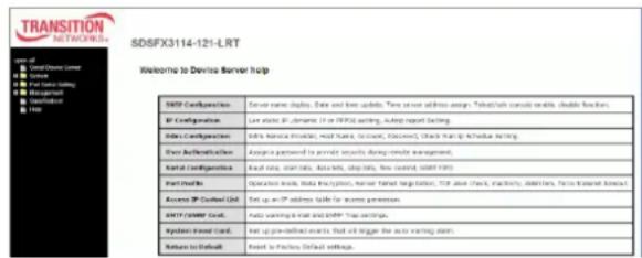
Help Screen
The Device Server helps screen is shown and described below.
SNTP Configuration: Server name display, Date and time update, Time server address assign, Telnet/ssh console enable, disable function.
text_image
TRANSITION NETWORKS SDSFX3114-121-LRT Welcome to Devise Server help SNSF Configuration Server name: dapius, Date and time updates. Time server address assign: "Tobet/ah console enable, double function. SF Configuration Live static SF, admin (0 or FPID setting, Auto report setting). Index Configuration Index name: master, web server, master server, master server, clock start & schedule setting. Short Authentication Assign password to sendir seconds during remote management. Kagal Configuration Read log, start date, data bits, stop date, low control, SNSF PFS Part Orders: Operation mode, Data Encryption, User Target registration, TCP area chart, Inactivity, Digitalis, Factor-based network Access SP Central Grid Set up as IP address table for access permission. HTTP CMMF Card... Auto warning a wait and APP Tree settings. Python Event Card... Net up pre-defined events that will trigger the auto warning plan. Return to Email Reset to Fraction Default settings.IP Configuration: Lan static IP, dynamic IP, or PPPOE setting, Autoip report Setting.
Ddns Configuration: Ddns Service Provider, Host Name, Account, Password, Check Wan Ip Schedule Setting.
User Authentication: Assign a password to provide security during remote management.
Serial Configuration: Baud rate, start bits, data bits, stop bits, flow control, UART FIFO.
Transition Networks
SDSFX311x-111-LRT User Guide
Port Profile: Operation mode, Data Encryption, Server Telnet Negotiation, TCP alive check, inactivity, delimiters, force transmit timeout.
Access IP Control List: Set up an IP address table for access permission.
SMTP/SNMP Conf.: Auto warning E-mail and SNMP Trap settings.
System Event Conf.: Set up pre-defined events that will trigger the auto warning alarm.
Return to Default: Reset to Factory Default settings.
5.1.2 Uninstall the SDS Manager
- Close the SDS-Manager if it is running.
- Select the Windows Start -> All Programs -> SDS Manager -> uninstall menu.
- A .bat file screen displays momentarily and then the SDS icon is removed from the Windows icon tray.
5.1.3 Messages
Message: There is a problem with this website's security certificate.
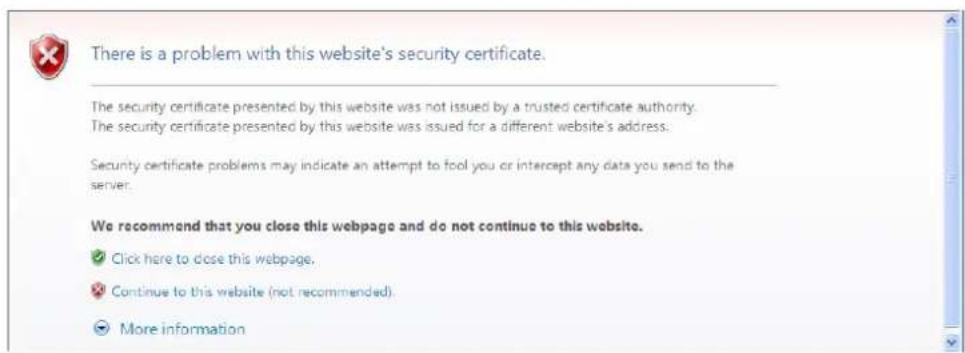
text_image
There is a problem with this website's security certificate. The security certificate presented by this website was not issued by a trusted certificate authority. The security certificate presented by this website was issued for a different website's address. Security certificate problems may indicate an attempt to fool you or intercept any data you send to the server. We recommend that you close this webpage and do not continue to this website. ✓ Click here to close this webpage. ✗ Continue to this website (not recommended). ✗ More informationMessage: SDS-Manager is running. Please close it, then do uninstall.
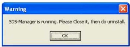
text_image
Warning SDS-Manager is running. Please Close it, then do uninstall. OK5.3 Configuration by SSH Console
5.3.1 Connect to SDS Commander
You can use an SSH tool (e.g., PuTTY) to access the SDS SSH console (shown below).
The default password is 'admin'. The SDS Commander functions are shown below.
**************************
*** TRANSITION Industrial Serial Device Server Commander ***
**************************
Input System Password: *****
----
[SUPERCOM iCOM3000 Series]
1. Overview
2. General Settings
3. Network Settings
4. Ports settings
5. Security(Accessible IP) Settings
6. Notification(Auto Warning) Settings
A. DDNS setting
C. Change Password
L. Load Factory Default
S. Save configuration
R. Reboot
Q. Exit & Logout

Select one function (0-9,A,C,L,S,R,Q):
Each of the SDS Commander functions is shown below.
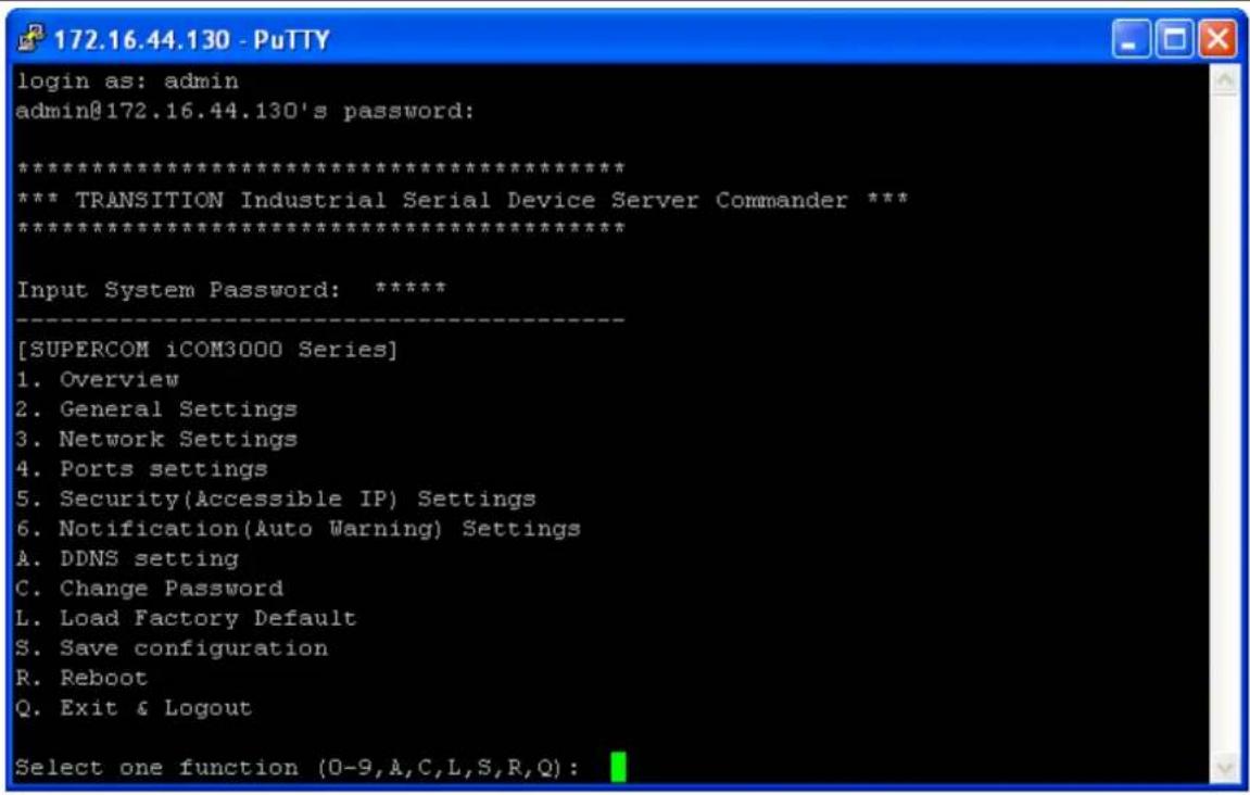
text_image
login as: admin admin@172.16.44.130's password: ************************** *** TRANSITION Industrial Serial Device Server Commander *** ************************** Input System Password: **** [SUPERCOM iCOM3000 Series] 1. Overview 2. General Settings 3. Network Settings 4. Ports settings 5. Security(Accessible IP) Settings 6. Notification(Auto Warning) Settings A. DDNS setting C. Change Password L. Load Factory Default S. Save configuration R. Reboot Q. Exit & Logout Select one function (0-9,A,C,L,S,R,Q):Figure 5-30. SSH Connection - Main menu
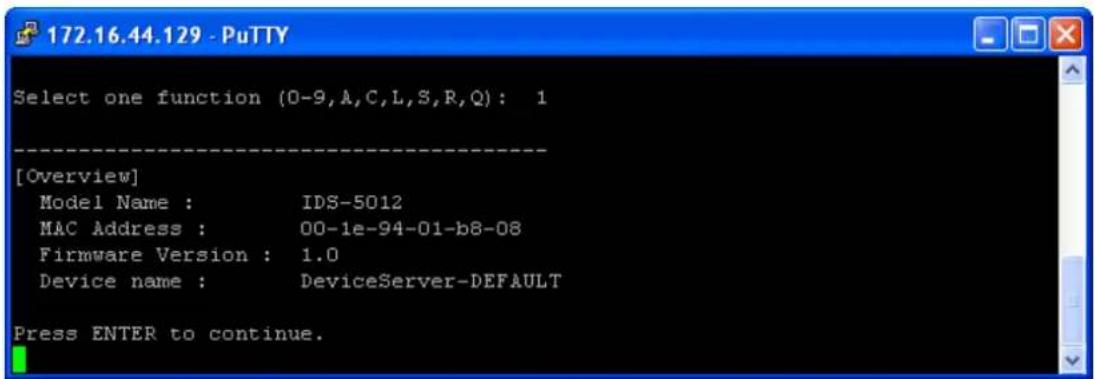
text_image
172.16.44.129 - PuTTY Select one function (0-9,A,C,L,S,R,Q): 1 [Overview] Model Name : IDS-5012 MAC Address : 00-1e-94-01-b8-08 Firmware Version : 1.0 Device name : DeviceServer-DEFAULT Press ENTER to continue.Figure 5-31. SSH Connection - 1. Overview menu
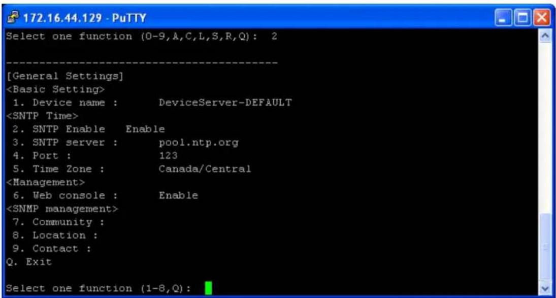
text_image
[General Settings]Figure 5-32. SSH Connection - 2. General Settings
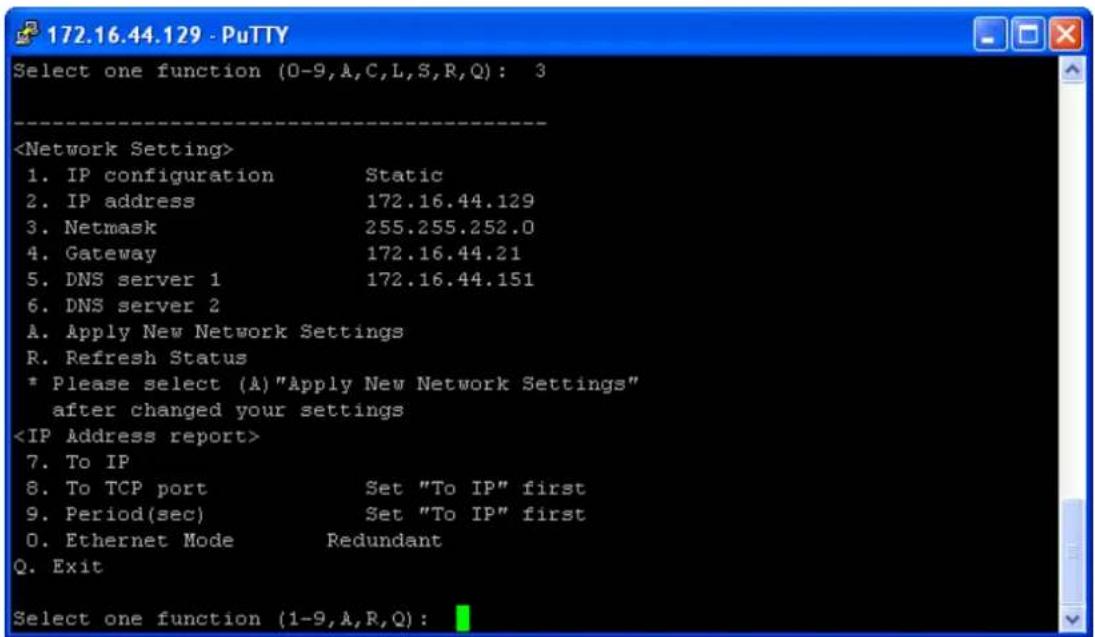
text_image
172.16.44.129 - PuTTY Select one function (0-9,A,C,L,S,R,Q): 3Figure 5-33. SSH Connection - 3. Network Settings

text_image
172.16.44.129 - PuTTY Select one function (0-9,A,C,L,S,R,Q): 4 [Ports setting] 1. port1 (Port0) Q. Exit Select port or (Q)uit:Figure 5-34. SSH Connection - 4. Ports Settings
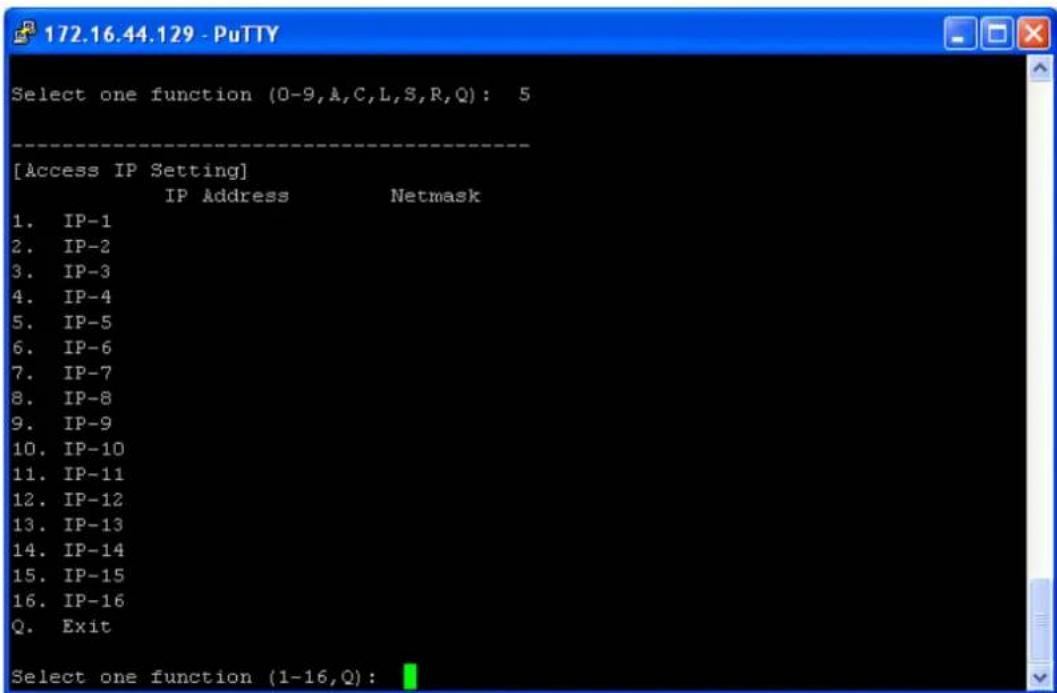
text_image
172.16.44.129 - PuTTY Select one function (0-9,A,C,L,S,R,Q): 5 [Access IP Setting] IP Address Netmask 1. IP-1 2. IP-2 3. IP-3 4. IP-4 5. IP-5 6. IP-6 7. IP-7 8. IP-8 9. IP-9 10. IP-10 11. IP-11 12. IP-12 13. IP-13 14. IP-14 15. IP-15 16. IP-16 Q. Exit Select one function (1-16,Q):Figure 5-35. SSH Connection - 5. Security(Accessible IP) Settings

text_image
172.16.44.130 - PuTTY Select one function (0-9,A,C,L,S,R,Q): 6 [Notification Settings] 1. SNMP Trap setting 2. Email Notification settings 3. System Log setting 4. Fault LED and relay Q. Exit Select one function (1-4, Q):igure 5-36. SSH Connection - 6. Notification(Auto Warning) Settings
Transition Networks
SDSFX311x-111-LRT User Guide
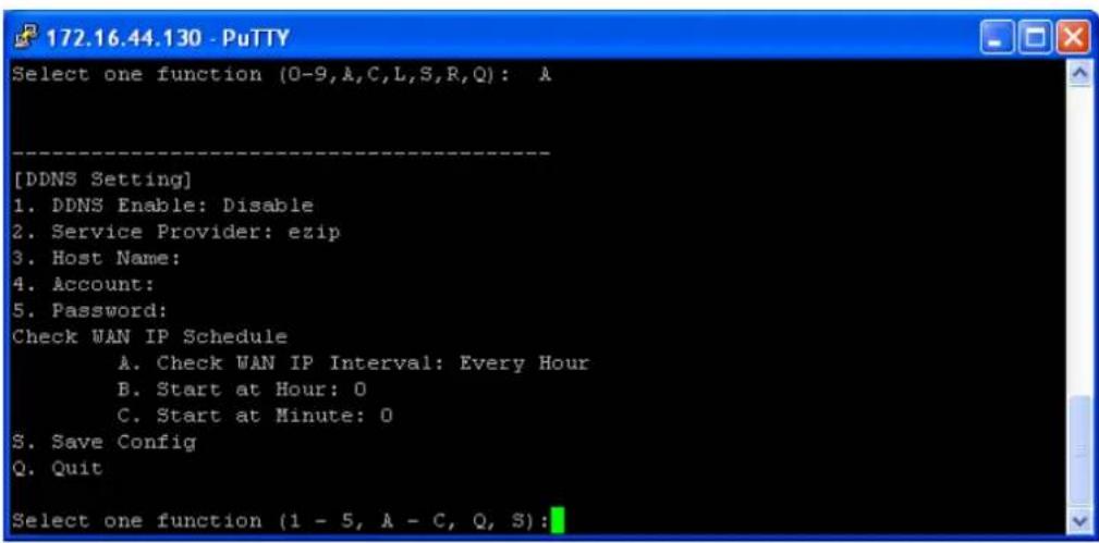
text_image
[DDNS Setting] 1. DDNS Enable: Disable 2. Service Provider: ezip 3. Host Name: 4. Account: 5. Password: Check WAN IP Schedule A. Check WAN IP Interval: Every Hour B. Start at Hour: 0 C. Start at Minute: 0 S. Save Config Q. Quit Select one function (1 - 5, A - C, Q, S):Figure 5-37. SSH Connection - A. DDNS setting
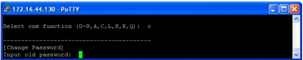
text_image
172.16.44.130 - PuTTY Select one function (0-9,A,C,L,S,R,Q): c [Change Password] Input old password:Figure 5-38. SSH Connection - C. Change Password

text_image
172.16.44.129 - PuTTY Select one function (0-9,A,C,L,S,R,Q): 1 [Load Default] Are you sure? (Y/N)Figure 5-39. SSH Connection - L. Load Factory Default
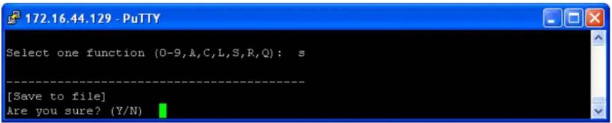
text_image
172.16.44.129 - PuTTY Select one function (0-9,A,C,L,S,R,Q): s [Save to file] Are you sure? (Y/N)Figure 5-40. SSH Connection - S. Save configuration

text_image
172.16.44.129 - PuTTY Select one function (0-9,A,C,L,S,R,Q): r [Reboot System] Are you sure? (Y/N)Figure 5-41. SSH Connection - R. Reboot
7. Technical Specifications
| Network Interface | |
| Ethernet | 1x 100Base-FX with SC connector |
| Protocols | ICMP, IP, TCP, UDP, DHCP, BOOTP, SSH, DNS, SNMP V1/V2c, HTTPS, SMTP, SSL, PPPoE, DDNS |
| Serial Interface | |
| Serial Interface | (1) DB9MProtocols: RS-232/422/485 (2 and 4 wire)Baud Rates: 110bps to 460KbpsData Bits: 5, 6, 7, 8Partiy: Odd, Even, None, SpaceStop Bits: 1, 1.5, 2RS-232: TxD, RxD, RTS, CTS, DTR, DSR, DCD, RI, GNDRS-422: Tx+. Tx-, Rx+, Rx-, GNDRS-485 (4 wire): Tx+. Tx-, Rx+, Rx-, GNDRS-485 (2 Wire): Data+, Data-, GNDFlow Control: XON/XOFF, RTS/CST, DTR/DSR |
| Connectors | SDSFX3113-111-LRT: One 100BASE-FX 1310nm MM (SC) [2 km/1.2 mi.] and one RS232/422/485 DB9 port.SDSFX3114-111-LRT: One 100BASE-FX 1310nm SM (SC) (30 km/18.6 mi.] and one RS232/422/485 DB9 port. |
| Serial Line Protection | Built-in15KV ESD protection2KV DC isolation for each port (SDSFX311x-111-LRT-I+ only) |
| LED Indicators | PWR (1)(2) / Ready:1) Red On: Power is on and booting up.Red Blinking: Indicates an IP conflict, or DHCP or BOOTP server did not respond properly.2) Green On: Power is on and functioning normally.Green Blinking: Located by Administrator.ETH1(2) Link / ACT:Green ON/Blinking:100 Mbps EthernetSerial TX / RX LEDS: |
Transition Networks
SDSFX311x-111-LRT User Guide
| Red: Serial port is receiving dataGreen: Serial port is transmitting data. | |
| Power Requirements | |
| Power Input | PWR1/2: 12~48VDC3-PIN Terminal Block, power jack |
| Reverse Polarity Protection Present at terminal block | |
| Power Consumption 4 Watts | |
| Software Utility | |
| Utility | SDS-Manager for Windows NT/2000/XP/ 2003/VISTA/ Windows 7 (32/64 bits)Device discoveryAuto IP reportDevice setting (run-time change, no rebooting)Access control listGroup settingDevice monitoringSerial port monitoringLog infoGroup Firmware update |
| Serial Mode | Virtual Com / TCP Server / TCP Client / UDP /Serial TunnelTCP Alive Check TimeoutInactivity TimeoutDelimiter for Data PackingForce TX Timeout for Data Packing |
| Multiple Link | 5 Hosts simultaneous connection: Virtual Com /TCP server / TCP Client / UDP |
| VCOM Driver | Windows NT/2000/XP/2003/VISTA/Windows 7 (32/64 bits) |
| Configuration | Web HTTPS console, SSH console, Console CommandSDS-Manager for Windows NT/2000/XP/VISTA |
| Environmental | |
| Operating Temperature | -40 to 70°C (-40 to 185°F) |
| Operating Humidity | 5% to 95%(Non-condensing) |
| Storage Temperature | -40 to 85°C (-40 to 185°F) |
| Mechanical | |
| Dimensions(W x D x H) | 72mm(W)x123.4mm(D)x29.4mm(H) |
| Casing | IP-30 protection |
| Regulatory Approvals | |
| Shock IEC 60068-2-27 | |
| Free Fall | IEC 60068-2-32 |
| Vibration IEC 60068-2-6 | |
| EMI | FCC Part 15, CISPR22 / EN55022 Class A |
| EMS | EN61000-4-2 (ESD), EN61000-4-3 (RS); EN61000-4-4 (EFT); EN61000-4-5 (Surge); EN61000-4-6 (CS) |
| MTBF 561,145 Hrs. | |
| Warranty Lifetime | |
8. Troubleshooting
- Is the PWR1 or PWR2 LED blinking Red?
YES
- Check if an IP conflict exists. Re-install the device. See the Network Setting section.
- Check if DHCP or BOOTP server did not respond properly. See the installation instructions.
-
Proceed to step 2.
-
Is one of the Green Power LEDs (PWR, PWR1 PWR3) lit?
NO
• Is the power source live and to spec?
- Is the power adapter properly installed?
- Proceed to step 3.
YES
- Check the P7 and P8 LEDs. Are the Green for port Link/Act or Amber for Link LEDs lit?
NO
- Verify that the fiber cable requirements are met.
- Proceed to step 4.
YES
For unresolved issues:
- Contact Technical Support: US/Canada: 1-800-260-1312, International: 00-1-952-941-7600.
Troubleshooting Q&A
Q1: Should SDS-Manager x64 install into "Program Files (x86)" directory on Win7 x64 (or into "Program Files" directory)?
A1: Yes, the difference of the X64 version of SDS-Manager is the VCOM driver install location, but not necessarily the other files. So it will be put into "Program Files (x86)" in the default directory.
Q2: SDS-Manager GUI indicates the DUT's DB9 port being set to RS232 while the DUT's hardware DIP switch indicates that it is set to RS485 (which takes precedence? Why is there a discrepancy)
A2: The dip switch is for the RS-422/485 termination but not the mode. The mode can only be changed by using software.
Q3: Using the SDS-Manager to map a device to a COM port, and then using TeraTerm to connect to that COM port results in the COM port being listed twice in TeraTerm (a COM port should only show up once).
A3: This problem not found when using other Terminal software.
Q4: COM ports mapped by the SDS-Manager do not show up in Windows Device Manager (they should).
A4: It's designed not to show up in Windows' Device Manager.
Q5: While setting up a second unit, this warning displayed during discovery of device that was directly connected to the second PC and nothing else: "IP 192.168.1.77 will be collision with other device. Please select another IP again." The other device server used the same IP, but they weren't connected together, which means either there was a bug and the warning was invalid, or the devices somehow communicated wirelessly.
A5: Check if this PC is connected with any device with the same IP address. Try to clear the ARP table of this PC.
9. Safety Warnings and Cautions
These products are not intended for use in life support products where failure of a product could reasonably be expected to result in death or personal injury. Anyone using this product in such an application without express written consent of an officer of Transition Networks does so at their own risk, and agrees to fully indemnify Transition Networks for any damages that may result from such use or sale.

Attention: this product, like all electronic products, uses semiconductors that can be damaged by ESD (ostatic discharge). Always observe appropriate precautions when handling.

Warning: Potential for damage to equipment or personal injury.

Warning: Risk of Electrical Shock

Functional grounding point

Protective grounding point

Special considerations
10. Service, Warranty and Tech Support
Contact Us
Technical Support
Technical support is available 24 hours a day.
US and Canada: 1-800-260-1312
International: 00-1-952-941-7600
Transition Now 7:00 AM to 6:00 PM CST
Voice Mail: 800-260-1312 x 579 or 952-941-7600 x 579
Chat live via the Web with Transition Networks Technical Support.
Log onto www.transition.com and click the Tech Support/Transition Now link.
Web-Based Seminars
Transition Networks provides seminars via live web-based training.
Log onto www.transition.com and click the Learning Center link.
To ask a question anytime, send an e-mail to our technical support staff at
techsupport@transition.com.
Address
Transition Networks
10900 Red Circle Drive,
Minnetonka, MN 55343, U.S.A.
Telephone: 952-941-7600
Toll free: 800-526-9267
Fax: 952-941-2322
Warranty
This warranty is your only remedy. No other warranties, such as fitness for a particular purpose, are expressed or implied. Transition Networks is not liable for any special, indirect, incidental or consequential damages or losses, including loss of data, arising from any cause or theory. Authorized resellers are not authorized to extend any different warranty on transition networks' behalf.
Effective for products shipped May 1, 1999 and after. Every Transition Networks' labeled product purchased after May 1, 1999 will be free from defects in material and workmanship for its lifetime. This warranty covers the original user only and is not transferable.
What the Warranty Does Not Cover
This warranty does not cover damage from accident, acts of God, neglect, contamination, misuse or abnormal conditions of operation or handling, including over-voltage failures caused by use outside the product's specified rating, or normal wear and tear of mechanical components. If the user is unsure of the proper means of installing or using the equipment, contact Transition Networks' free technical support services.
Establishing Original Ownership
To establish original ownership and provide date of purchase, please complete and return the registration card accompanying the product or register the product on-line on our product registration page.
Transition Networks will at its option:
- Repair the defective product to functional specifications at no charge
- Replace the product with an equivalent functional product
- Refund the purchase price of a defective product
Who to Contact for Returns
To return a defective product for warranty coverage, contact Transition Networks' technical support department for a return authorization number. Transition's technical support department can be reached through any of the following means:
How and Where to Send Returns
Send the defective product postage and insurance prepaid to the following address:
Transition Networks, Inc.
10900 Red Circle Drive
Minnetonka, MN 55343 USA
Attn: RETURNS DEPT: CRA/RMA # ____
Failure to properly protect the product during shipping may void this warranty. The return authorization number must be written on the outside of the carton to ensure its acceptance. We cannot accept delivery of any equipment that is sent to us without a CRA or RMA number.
CRA's are valid for 60 days from the date of issuance. An invoice will be generated for payment on any unit(s) not returned within 60 days.
Upon completion of a demo/ evaluation test period, units must be returned or purchased within 30 days. An invoice will be generated for payment on any unit(s) not returned within 30 days after the demo/ evaluation period has expired.
The customer must pay for the non-compliant product(s) return transportation costs to Transition Networks for evaluation of said product(s) for repair or replacement. Transition Networks will pay for the shipping of the repaired or replaced in-warranty product(s) back to the customer (any and all customs charges, tariffs, or/and taxes are the customer's responsibility).
Before making any non-warranty repair, Transition Networks requires a \200.00 charge plus actual shipping costs to and from the customer. If the repair is greater than \200.00, an estimate is issued to
the customer for authorization of repair. If no authorization is obtained, or the product is deemed ‘not repairable’, Transition Networks will retain the \$200.00 service charge and return the product to the customer not repaired. Non-warranted products that are repaired by Transition Networks for a fee will carry a 180-day limited warranty. All warranty claims are subject to the restrictions and conventions set forth by this document.
Transition Networks reserves the right to charge for all testing and shipping incurred, if after testing, a return is classified as "No Problem Found."
THIS WARRANTY IS YOUR ONLY REMEDY. NO OTHER WARRANTIES, SUCH AS FITNESS FOR A PARTICULAR PURPOSE, ARE EXPRESSED OR IMPLIED. TRANSITION NETWORKS IS NOT LIABLE FOR ANY SPECIAL, INDIRECT, INCIDENTAL OR CONSEQUENTIAL DAMAGES OR LOSSES, INCLUDING LOSS OF DATA, ARISING FROM ANY CAUSE OR THEORY. AUTHORIZED RESELLERS ARE NOT AUTHORIZED TO EXTEND ANY DIFFERENT WARRANTY ON TRANSITION NETWORKS'S BEHALF.
Customer Pays Non-Compliant Return Costs
The customer must pay the non-compliant product(s) return transportation cost to Transition Networks for evaluation of said product(s) for repair or replacement. Transition Networks will pay for shipping the repaired or replaced in-warranty product(s) back to the customer (any and all customs charges, tariffs, or/and taxes are the customer's responsibility).
Non-Warranty Repair Costs
Before making any non-warranty repair, Transition Networks requires a \200 charge, plus actual shipping costs to and from the customer. If the repair is greater than \200, an estimate is issued to the customer for authorization before making the repair. If no authorization is obtained, or the product is deemed not repairable, Transition Networks will retain the \$200 service charge and return the product to the customer not repaired.
Repaired Non-Warranty Products
Non-warranted products repaired by Transition Networks for a fee will carry a 180-day limited warranty. All warranty claims are subject to the restrictions and conventions set forth by this document.
Transition Networks reserves the right to charge for all testing and shipping incurred, if after testing, a return is classified as “No Problem Found.”
11. Compliance Certifications
- EN60950
- UL508
Declaration of Conformity
DECLARATION OF CONFORMITY
Transition Networks, Inc.
Manufacturer's Name
10900 Red Circle Drive, Minnetonka, Minnesota 55343 U.S.A.
Manufacturer's Address
DECLARES THAT THE PRODUCT(S)
SDSTX3110-121-LRT and SDSTX3110-124-LRT
SDSFX3113-111-LRT and SDSFX3114-111-LRT
CONFORM TO THE FOLLOWING PRODUCT REGULATIONS:
FCC Part 15, CISPR22 / EN55022 Class A
EN61000-4-2 (ESD), EN61000-4-3 (RS); EN61000-4-4 (EFT);
EN61000-4-5 (Surge); EN61000-4-6 (CS)
EN61000-4-8. EN61000-4-11.
IEC60068-2-27, IEC60068-2-32, IEC6068-2-6
I, the undersigned, hereby declare that the equipment specified above conforms to the above Directive(s) and Standards(s).
Minnetonka, Minnesota
Place
March 12, 2015
Date
Stephen Autumn
Signature
Stephen Anderson
Full Name
Vice President of Engineering
Position
31415
European Regulations
WARNING: This is a Class A product. In a domestic environment, this product could cause radio interference in which case the user may be required to take adequate measures.
In accordance with European Union Directive 2002/96/EC of the European Parliament and of the Council of 27 January 2003, Transition Networks will accept post usage returns of this product for proper disposal. The contact information for this activity can be found in the 'Contact Us' portion of this document.
CAUTION: RJ connectors are NOT INTENDED FOR CONNECTION TO THE PUBLIC TELEPHONE

NETWORK. Failure to observe this caution could result in damage to the public telephone network.
Electrical Safety Warnings

Electrical Safety
IMPORTANT: This equipment must be installed in accordance with safety precautions.
| Rev | Date | Description of Changes |
| A 5/15/15 | Initial release for SDSFX311x-111-LRT at v 1.11.Firmware: SDSFX3113-111-LRT_V1.1_20150421.binFirmware: SDSFX3114-111-LRT_V1.1_20150421.bin | |
Trademark notice
All trademarks and registered trademarks are the property of their respective owners. All other products or service names used in this publication are for identification purposes only, and may be trademarks or registered trademarks of their respective companies. All other trademarks or registered trademarks mentioned herein are the property of their respective holders.
Copyright restrictions
© 2015 Transition Networks, Inc. All rights reserved. No part of this work may be reproduced or used in any form or by any means (graphic, electronic, or mechanical) without written permission from Transition Networks.
Address comments on this product or manual to:
Transition Networks Inc.
10900 Red Circle Drive
Telephone: +1-952-941-7600 / Toll Free: 800-526-9267 / Fax: 952-941-2322
E-Mail: customerservice@transition.com / techsupport@transition.com sales@transition.com / info@transition.com
Transition Networks
10900 Red Circle Drive
Minnetonka, MN 55343 USA
Tel: 952-941-7600 or 1-800-526-9267
Fax: 952-941-2322
Copyright© 2014, 2015 Transition Networks. All rights reserved.
Printed in the U.S.A.
SDSFX311x-111-LRT User Guide 33608 Rev A