AA72-4F1 - Unspecified Daytronic - Free user manual and instructions
Find the device manual for free AA72-4F1 Daytronic in PDF.

User questions about AA72-4F1 Daytronic
0 question about this device. Answer the ones you know or ask your own.
Ask a new question about this device
Download the instructions for your Unspecified in PDF format for free! Find your manual AA72-4F1 - Daytronic and take your electronic device back in hand. On this page are published all the documents necessary for the use of your device. AA72-4F1 by Daytronic.
USER MANUAL AA72-4F1 Daytronic
PLEASE NOTE: In this manual, "AA72" will be used to refer to BOTH the two-channel Model AA72-2 AND the four-channel Model AA72-4, in cases where it is not necessary to distinguish them.
1 GENERAL DESCRIPTION AND SPECIFICATIONS
The Models AA72-2 and AA72-4 are general-purpose two- and four-channel conditioners (respectively) for use with DC-excited load cells, pressure sensors, and any other conventional strain gage transducer employing a 4-arm bridge of nominal 350 Ω or higher, with a full-scale range of 0.75, 1.50, or 3.00 mV/V.
The AA72's advanced design techniques overcome errors that traditionally plague the strain-gage conditioning process. Separate excitation for each channel uses remote sensing of bridge voltage and is slaved to a common System Reference Voltage. The result is consistently stable ratiometric measurement, unaffected by possible power-supply drift. Input impedances in excess of 10,000 MΩ are presented to signal leads to eliminate cable resistance as a source of error. Allowable cable length has virtually no practical limits.
The AA72 features selectable per-channel excitation (1, 5, or 10 V-DC). Using low excitation helps reduce gage heating effects in stress analysis of materials with low thermal conductivity. Table 1 gives the full-scale mV/V ranges that correspond to each excitation level.
Like most Daytronic "Advanced Analog" ("AA") cards, the AA72 features optional PROGRAMMABLE LOW-PASS ACTIVE FILTERING for the removal of unwanted high-frequency measurement-signal components. Selectable analog filtering is offered for the AA72 either from 0.2 through 200 Hz in 16 steps ("F1" filtering) or from 2 through 2000 Hz in 16 steps ("F2" filtering). Or, if desired, a fixed filter of either 10 or 50 Hz for all channels may be specified at the time of order. When the AA72 is used in System 10, its filter cutoff values are set by means of an on-board 16-position switch for each channel.
A nominal ±5-V ANALOG OUTPUT is produced by each active AA72 input channel, for purposes of real-time signal monitoring. Each of these “Auxiliary Outputs” is available on a corresponding mainframe wire-wrap pin. Each output may be individually set, if desired, to represent the prefiltered value of the corresponding input. When such is the case, the output bandwidth is limited only by that of the AA72 card (see “Specifications”).
A convenient shunt calibration technique is provided. Each channel's shunt resistor may be switched in and out by software command or by means of logic-level inputs through the rear I/O CONNECTOR.
When connected to an optional Model 10CJB-2 Dual Bridge Completion Card (or equivalent circuitry supplied by the user), the AA72 can accept input from a two-wire 1/4-bridge, three-wire 1/4-bridge, 1/2-bridge, or full-bridge strain gage configuration. See Section 4 for details.
The AA72 is manufactured using the latest surface-mount technology, resulting in the highest immunity to shock and vibration. As explained in Section 2, I/O connections are via secure, clearly labelled screw terminals in a special AA72 CONNECTOR ASSEMBLY.
Fig. 1 Model AA72-2 / AA72-4 Modular Card Components

flowchart
graph LR
    A["I/O Connector"] --> B["Conditioner Tile Chans. 3 & 4<br>(Model AA72-4 Only)"]
    A --> C["Filter Chans.<br>3 & 4<br>(Model AA72-4 Only)"]
    A --> D["Filter Chans.<br>1 & 2"]
    E["FOR FUTURE USE"] --> F[" "] --> G[" "]
Fig. 1 shows the stand-off circuit boards (or "tiles") that provide the analog filtering for an AA72 card's data channels.
WARNING
THE CONDITIONER TILE FOR CHANNELS 3 AND 4 OF A MODEL AA72-4 IS TO BE INSTALLED OR REMOVED ONLY BY A QUALIFIED TECHNICIAN, SINCE SUBSEQUENT REALIGNMENT OF THE AA72 CARD IS REQUIRED. FILTER TILES, HOWEVER, MAY BE INSTALLED OR REMOVED BY THE USER, IN THE FIELD. CONTACT THE DAYTRONIC SERVICE DEPARTMENT FOR COMPLETE INSTRUCTIONS.
THE FOLLOWING AA72-2 / AA72-4 VERSIONS ARE CURRENTLY AVAILABLE:
- Model AA72-2F010—Two input channels, with FIXED 10-Hz FILTERING for each
- Model AA72-2F050—Two input channels, with FIXED 50-Hz FILTERING for each
- Model AA72-2F1—Two input channels, with "F1" PROGRAMMABLE FILTERING for each
- Model AA72-2F2—Two input channels, with "F2" PROGRAMMABLE FILTERING for each
- Model AA72-4F010—Four input channels, with FIXED 10-Hz FILTERING for each
- Model AA72-4F050—Four input channels, with FIXED 50-Hz FILTERING for each
- Model AA72-4F1—Four input channels, with "F1" PROGRAMMABLE FILTERING for each
- Model AA72-4F2—Four input channels, with "F2" PROGRAMMABLE FILTERING for each
ADDITIONAL AA72-2 / AA72-4 SPECIFICATIONS
Number of Input Channels: Two for Model AA72-2; four for Model AA72-4
Transducer Types: Conventional 4-arm strain gage bridges, nominal 350 ohms (or higher); 1/4- and 1/2-bridge gage configurations can be accommodated by means of the Model 10CJB-2 Dual Bridge Completion Card described in Section 4 (or equivalent external bridge-completion circuitry supplied by the user)
Input Ranges (Full-Scale): See Table 1; automatically selected—on an individual channel basis—when the channel is configured; for System 10 channel “type” codes assigned to AA72 data channels, see Table 1. Since channel zeroing is by digital techniques, no input balance control is provided. The allowable input range, therefore, must include any initial unbalance (which, in commercially produced strain gage transducers, is usually negligible). Other transducers may have to be externally trimmed to be used with the Model AA72, if zero unbalance exceeds 20% of full scale.
Excitation (per channel): Selectable 1, 5, or 10 V-DC (i.e., ±0.5, ±2.5, or ±5 V-DC, respectively), nominal; ±40 mA, maximum, for each voltage, subject to 120 mA total current draw for all four channels*
Amplifier (per channel):
Normal-Mode Range: ±40 mV operating (±3.6 mV/V with 10-V excitation); ±8 V without instrument damage
Common-Mode Range: ±1 V operating; ±8 V without instrument damage
Common-Mode Rejection Ratio: DC and at 60 Hz: -120 dB
Input Impedance: Differential: greater than 10,000 MΩ; Common-Mode: greater than 10,000 MΩ
Offset: Initial: ±0.02 mV; vs. Temperature: ±1 μV/°C; vs. Time: ±5 μV/month
Gain Accuracy: ±0.02% of full scale
Gain Stability: vs. Temperature: ±50 ppm/°C; vs. Time: ±20 ppm/month
Filter (per channel): 3-pole modified Butterworth
"F1" Programmable Filtering (all four channels): Switch- or software-selectable to one of 16 different cutoff frequencies: 0.2; 0.4; 0.8; 1.0; 1.6; 2.0; 4.0; 5.0; 8.0; 10; 20; 25; 40; 50; 100; or 200 Hz (see Table 2)
"F2" Programmable Filtering (all four channels): Switch- or software-selectable to one of 16 different cutoff frequencies: 2; 4; 8; 10; 16; 20; 40; 50; 80; 100; 200; 250; 400; 500; 1000; or 2000 Hz (see Table 3)
Fixed Filtering (all four channels): 10 or 50 Hz (see Table 4)
Auxiliary Outputs: Nominal ±5 V-DC signals available on mainframe wire-wrap pins**; individually jumper-selectable to represent either the filtered or prefiltered (5-kHz bandwidth) reading of the channel
Power-Supply Slot Allotment: Maximum consumption of supply current from the Conditioner Card Slot is 200 mA (the actual consumption for any given AA72 channel will depend on its transducer bridge resistance and excitation level)
Table 1 Model AA72 Ranges and "Type" Codes
Channel
1-V Excitation 5V Excitation 10-V Excitation "Type" Code
7.5 mV/V 1.5 mV/V 0.75 mV/V 70
15.0 mV/V 3.0 mV/V 1.50 mV/V 71
30.0 mV/V 6.0 mV/V 3.00 mV/V 72
Table 2 "F1" Programmable Filter Characteristics for "AA" Cards
| Bandwidth Step-Response Settling Time | |||||
| Selected Response Response to 1% of to 0.1% of to 0.02% of Frequency at -3 dB at -60 dB final value final value final value (Hz) (Hz) (Hz) (Hz) (msec) (msec) (msec) | |||||
| 0.2 | 0.2 | 3.9 | 3500 | 4250 | 4750 |
| 0.4 | 0.4 | 7.8 | 1750 | 2125 | 2375 |
| 0.8 | 0.8 | 16 | 875 | 1063 | 1188 |
| 1.0 | 1.0 | 20 | 700 | 850 | 950 |
| 1.6 | 1.6 | 31 | 438 | 531 | 594 |
| 2.0 | 2.0 | 39 | 350 | 425 | 475 |
| 4.0 | 4.0 | 78 | 175 | 213 | 238 |
| 5.0 | 5.0 | 98 | 140 | 170 | 190 |
| 8.0 | 8.0 | 156 | 88 | 106 | 119 |
| 10.0 | 10.0 | 195 | 70 | 85 | 95 |
| 20.0 | 20.0 | 390 | 35 | 43 | 48 |
| 25.0 | 25.0 | 488 | 28 | 34 | 38 |
| 40.0 | 40.0 | 780 | 18 | 21 | 24 |
| 50.0 | 50.0 | 975 | 14 | 17 | 19 |
| 100.0 | 100.0 | 1950 | 7.0 | 8.5 | 9.5 |
| 200.0 | 200.0 | 3900 | 3.5 | 4.3 | 4.8 |
Table 3 "F2" Programmable Filter Characteristics for "AA" Cards
| Bandwidth Step-Response Settling Time | |||||
| Selected Response Response to 1% of to 0.1% of to 0.02% of Frequency at -3 dB (Hz) | at -60 dB (Hz) | final value final value final value (msec) (msec) (msec) | |||
| 2 | 2 | 40 | 375 | 430 | 480 |
| 4 | 4 | 80 | 190 | 215 | 240 |
| 8 | 8 | 160 | 90 | 110 | 120 |
| 10 | 10 | 200 | 75 | 90 | 100 |
| 16 | 16 | 320 | 45 | 55 | 60 |
| 20 | 20 | 400 | 38 | 43 | 50 |
| 40 | 20 | 800 | 18 | 22 | 25 |
| 50 | 50 | 1000 | 15 | 18 | 20 |
| 80 | 80 | 1600 | 9.0 | 11 | 12 |
| 100 | 100 | 2000 | 7.5 | 9.0 | 10 |
| 200 | 200 | 4000 | 4.0 | 4.5 | 5.0 |
| 250 | 250 | 5000 | 3.0 | 3.5 | 4.0 |
| 400 | 400 | 8000 | 2.0 | 2.2 | 2.5 |
| 500 | 500 | 10000 | 1.5 | 2.0 | 2.0 |
| 1000 | 1000 | 20000 | 0.75 | 0.9 | 1.0 |
| 2000 | 2000 | 40000 | 0.4 | 0.5 | 0.55 |
Table 4 Fixed Filter Characteristics for "AA" Cards
| Bandwidth Step-Response Settling Time | ||
| Response Response to 1% of to 0.1% of to 0.02% of Filter at -3 dB at -60 dB final value final value final value Designation (Hz) (Hz) (msec) (msec) | ||
| “F010” 10 195 70 | 85 | 95 |
| “F050” 50 975 14 | 17 | 19 |
2 TRANSDUCER CONNECTIONS
The Model AA72's rear I/O CONNECTOR mates with the special AA72 CONDITIONER CONNECTOR, via the cable connections shown in Fig. 4. Mounted on the internal board of the connector assembly (shown in Fig. 2) is a block of eleven clearly labelled screw terminals for each of the AA72's four possible input channels.
To access the connector board, simply remove the screws that hold together both halves of the connector housing. Use the two internal clamp bars to secure transducer cables once all leads have been connected.
The connector assembly's mounting screws are designed to secure the connector to the rear of the system mainframe and to provide a solid GROUND CONNECTION for cable "shields" via the two L-shaped ground lugs. An offset in the mounting holes ensures that the connector cannot be attached upside down.
With regard to AA72 cabling, please note the following:
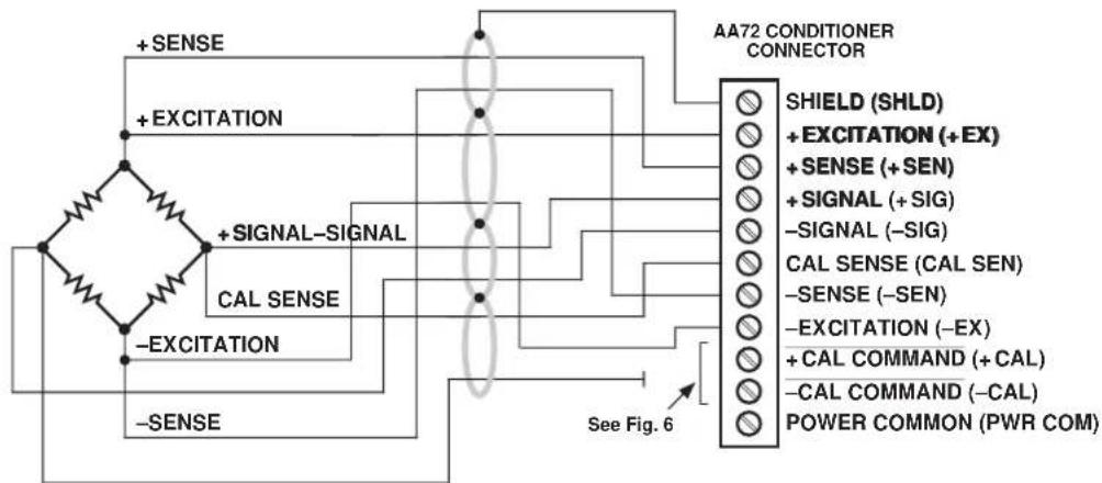
a. 4-wire cabling to a full-bridge strain gage transducer is given in Fig. 4(a), and is to be used when the cable is under 20 feet in length. In this case, the +SENSE and -SENSE lines are tied to the corresponding EXCITATION lines (and also the CALIBRATION SENSE line to the +SIGNAL line) at the CONDITIONER CONNECTOR. It is recommended that the resistance of the conductors not exceed 0.0001 of the bridge resistance.
b. 8-wire cabling to a full-bridge strain gage transducer is given in Fig. 4(b), and is to be used when the cable is 20 feet or longer, or when fine wire is used. In this case, the +SENSE and -SENSE lines are tied to the corresponding EXCITATION lines (and also the CALIBRATION SENSE line to the +SIGNAL line) at the transducer. Note also the extra wire connected to the -SIGNAL line at the transducer, but left unconnected at the AA72. This wire is to be paired with the CAL SENSE line to establish proper shielding and to avoid asymmetrical dynamic loading.
IMPORTANT: The ±EXCITATION, ±SENSE, and ±SIGNAL pins for an UNUSED STRAIN GAGE INPUT CHANNEL should be jumpered as shown in Fig. 3, below. If an input is left open, high-frequency oscillation can result, which can in turn produce significant interchannel crosstalk, and possibly inaccurate data readings.
ALSO NOTE: Logic connections for remote control of shunt calibration (using the CONDITIONER CONNECTOR'S "NOT ±CALIBRATE" terminals) are discussed in Section 3.d and shown in Fig 6. For connection of an optional Model 10CJB-2 Dual Bridge Completion Card to the AA72, see Section 4.b.
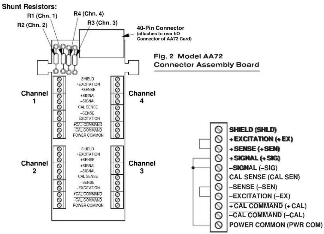
text_image
Shunt Resistors: R1 (Chn. 1) R2 (Chn. 2) R3 (Chn. 3) R4 (Chn. 4) 40-Pin Connector (attaches to rear I/O Connector of AA72 Card) Fig. 2 Model AA72 Connector Assembly Board Channel 1 SHIELD +EXCITATION +SENSE +SIGNAL -SIGNAL CAL SENSE -SENSE -EXCITATION +CAL COMMAND -CAL COMMAND POWER COMMON Channel 4 SHIELD +EXCITATION +SENSE +SIGNAL -SIGNAL CAL SENSE -SENSE -EXCITATION +CAL COMMAND -CAL COMMAND POWER COMMON Channel 3 SHIELD (SHLD) +EXCITATION (+EX) +SENSE (+SEN) +SIGNAL (+SIG) -SIGNAL (-SIG) CAL SENSE (CAL SEN) -SENSE (-SEN) -EXCITATION (-EX) +CAL COMMAND (+CAL) -CAL COMMAND (-CAL) POWER COMMON (PWR COM)Fig. 3 Jumpering of an Unused AA72 Strain Gage Input
Fig. 4 Model AA72 Transducer Cabling

text_image
AA72-2: Channel 1 or 2: AA72-4: Channel 1, 2, 3, or 4: -SIGNAL + EXCITATION + SIGNAL -EXCITATION See Fig. 6 AA72 CONDITIONER CONNECTOR SHIELD (SHLD) + EXCITATION (+ EX) + SENSE (+ SEN) + SIGNAL (+ SIG) -SIGNAL (-SIG) CAL SENSE (CAL SEN) -SENSE (-SEN) - EXCITATION (-EX) + CAL COMMAND (+ CAL) -CAL COMMAND (-CAL) POWER COMMON (PWR COM)AA72-2: Channel 1 or 2:
AA72-4: Channel 1, 2, 3, or 4:
flowchart
graph TD
    A["AC Source"] --> B["+ SENSE"]
    A --> C["+ EXCITATION"]
    A --> D["+ SIGNAL-SIGNAL"]
    A --> E["CAL SENSE"]
    A --> F["−EXCITATION"]
    A --> G["−SENSE"]
    H["AA72 CONDITIONER CONNECTOR"] --> I["SHIELD (SHLD)"]
    H --> J["+ EXCITATION (+EX)"]
    H --> K["+ SENSE (+SEN)"]
    H --> L["+ SIGNAL (+SIG)"]
    H --> M["−SIGNAL (−SIG)"]
    H --> N["CAL SENSE (CAL SEN)"]
    H --> O["−SENSE (−SEN)"]
    H --> P["−EXCITATION (−EX)"]
    H --> Q["+ CAL COMMAND (+CAL)"]
    H --> R["−CAL COMMAND (−CAL)"]
    H --> S["POWER COMMON (PWR COM)"]
    B --> T["See Fig. 6"]
EXTRA WIRE
(paired with "CAL SENSE."
UNCONNECTED at
Conditioner Connector)
Fig. 4(b) 8-Wire Strain Gage
Cabling (20 ft. or longer)
3
SETUP AND/OR OPERATING CONSIDERATIONS
3.a SELECTION OF EXCITATION LEVELS
To set the DC excitation for each AA72 channel, you should
- Remove the AA72 card from its mainframe slot. For "Card Insertion and Removal," see Manual Section 1.B. Since the AA72 is "hot-pluggable," you need NOT turn off mainframe power before removing the card.
- Refer to Fig. 5 and locate the EXCITATION PROGRAMMING JUMPER PINS. For the four-channel Model AA72-4, these pins are located between the main card and the Conditioner Tile for Channels 3 and 4, but are nonetheless easily accessible from the top of the card. One "minijumper" is provided for each channel, for interconnecting adjacent jumper pins.
- Position the jumper for each channel as shown in Fig. 5 to interconnect the pair of pins corresponding to the desired excitation voltage for that channel (1, 5, or 10 V).* You will need to use a small pair of needle-nosed pliers to move the jumper.
- Reinsert the AA72 card in its mainframe slot.
Fig. 5 Model AA72 Programming Jumper Pins and Filter Selection Switches

text_image
Excitation Programming Jumper Pins: 1051(V-DC) Filter Selection Switches (see Table 5) Chan. Chan. 1 2 Chan. Chan. 3 4 Chan. 4 Chan. 3 Chan. 2 Chan. 1 Output Mode Programming Jumper Pins: Chan. 4 Chan. 3 Chan. 2 Chan. 1
POSTFILTER (FILTERED) OUTPUT

PREFILTER (UNFILTERED) OUTPUT
3.b SELECTION OF ANALOG FILTERING
NOTE: If your AA72 card is equipped with FIXED ANALOG FILTERING, you may ignore this manual section.
When using an AA72 with PROGRAMMABLE ANALOG FILTERING in System 10, you may set an individual corner frequency for the analog filter of each active input channel,* as follows:
a. Remove the AA72 card from its slot (see Section 3.a, Step 1, above).
b. Refer to Fig. 5 and locate the 16-position FILTER SELECTION SWITCHES located between the main card and the Filter Tile(s).
c. Referring to Table 5, below, set each channel's switch for the desired frequency. You will need to use a small screwdriver (or equivalent tool) to set the switch to the appropriate number/letter.
d. Reinsert the AA72 card.
NOTE: In addition to the normal-mode analog filtering supplied by the AA72 card, System 10 can provide additional processor-controlled DIGITAL SMOOTHING on a per-channel basis. For each individual channel, you may indicate the desired amount of digital smoothing by applying a FILTER (FIL) command to that channel (see Manual Section 2.G.2).
Table 5 Model AA72 Filter Switch Settings
| Cutoff Frequency“F1” Filter “F2” Filter Switch Setting |
| 0.2 Hz 2 Hz 7 |
| 0.4 Hz 4 Hz 6 |
| 0.8 Hz 8 Hz 5 |
| 1.0 Hz 10 Hz 3 |
| 1.6 Hz 16 Hz 4 |
| 2.0 Hz 20 Hz 2 |
| 4.0 Hz 40 Hz 1 |
| 5.0 Hz 50 Hz F |
| 8.0 Hz 80 Hz 0 |
| 10 Hz 100 Hz E |
| 20 Hz 200 Hz D |
| 25 Hz 250 Hz B |
| 40 Hz 400 Hz C |
| 50 Hz 500 Hz A |
| 100 Hz 1000 Hz 9 |
| 200 Hz 2000 Hz 8 |
3.c SELECTION OF ANALOG OUTPUT MODES
As mentioned in Section 1, each AA72 channel's ±5-V ANALOG OUTPUT can be set to represent either the filtered or prefiltered reading of that channel. To set the output mode for each of your AA72's active input channels, ^* you should
- Remove the AA72 card from its slot (see Section 3.a, Step 1, above).
- Refer to Fig. 5 and locate the OUTPUT MODE PROGRAMMING JUMPER PINS beneath the AA72's Filter Tile(s). One "minijumper" is provided for each channel's set of three jumper pins.
- Position the jumper for each channel as shown in Fig. 5 to interconnect the pair of pins that corresponds to the desired output mode for that channel. You will need to use a small pair of needle-nosed pliers to move the jumper.
- Reinsert the AA72 card in its mainframe slot.
3.d CONFIGURATION AND CALIBRATION
For initial configuration of ANALOG INPUT CHANNELS dedicated to a specific Model AA72 card when used in System 10, see the general remarks on System 10 "real-channel" configuration in Manual Section 1.G.1 and elsewhere in the System 10 Guidebook. For AA72 channel "type" codes, see Table 1, above.
In System 10, you can use three calibration methods with the Model AA72, unless it is being used with a Model 10CJB-2 Dual Bridge Completion Card (in which case a special calibration procedure is required, as explained in Section 4.c, below):
CALCULATED CALIBRATION
This is generally the most convenient means of calibrating an AA72 channel, when the transducer's full-scale "mV/V" sensitivity rating is accurately known.
Thus, to calibrate an AA72-based Channel No. "x," you need only
- Turn ON the system EEPROM SWITCH and then apply the following MV/V CALIBRATION (MVV) command:
$$ \mathbf {M V V} \mathbf {x} = \mathbf {i}, \mathbf {u} [ \mathbf {C R} ] $$
For “i,” enter the manufacturer-supplied transducer sensitivity rating in “mV/V, full scale.” For a “Type 70” channel (7.5/1.5/0.75 mV/V, full scale), you should enter an “i” value greater than 0.02 and less than or equal to 1.00 (mV/V). For a “Type 71” channel (15.0/3.0/1.50 mV/V, full scale), you should enter a value greater than 0.04 and less than or equal to 2.00 (mV/V). For a “Type 72” channel (30.0/6.0/3.00 mV/V, full scale), you should enter a value greater than 0.80 and less than or equal to 4.00 (mV/V).
For “u,” enter the transducer’s nominal full-scale rating in whatever engineering units are desired for the channel’s data reading—but only if the channel is set for 10-volt excitation (Section 3.a). NOTE: If the channel being calibrated is set for 1-volt excitation, the “u” value to be entered should be 10 times the actual value of the nominal full-scale rating. If it is set for 5-volt excitation, “u” should be 2 times the actual value.
The MVV command will only work if Channel No. x has been assigned the proper "type" code ("70," "71," or "72").
- Zero the channel by commanding
ZRO x [CR]
Note that a channel calibrated by the MVV command will report measurement data to a precision matching that of the entered "u" value. If, for example, you're measuring "psi," and enter a "u" of "500," then all subsequent channel readings will be rounded to the nearest psi. If the entry is "500.0," then all readings will be rounded to the nearest tenth of a psi.
TWO-POINT (DEADWEIGHT) CALIBRATION
Using the standard ZERO (ZRO) and FORCE (FRC) commands, this conventional "zero and span" method can be applied to an AA72 channel if the full-scale "mV/V" rating of the channel's strain gage transducer is unknown, or if the final measurement accuracy provided by CALCULATED CALIBRATION does not meet the requirements of the measurement application. The mainframe's EEPROM Write Protect Switch must be ON for the ZRO and FRC commands to be effective. See Manual Section 1.G.5 for a general discussion of this calibration technique.
SIMULATED (SHUNT) CALIBRATION
Suitable for all AA72 excitation levels, this method is similar to the conventional TWO-POINT (DEADWEIGHT) procedure. The difference is that the second ("span") input is not produced by loading the source transducer, but by "simulating" a particular up-scale value of mechanical input. This known EQUIVALENT INPUT then serves to determine the SCALING FACTOR for the channel.
For an AA72 data channel, the equivalent input is produced by shunting a resistor of known magnitude across one arm of the strain gage bridge, thereby simulating a known value of input for either a positive or negative up-scale reading. If the transducer manufacturer has supplied the exact value of the transducer's equivalent input, it can be used as a reference point for calibrating the channel.
Equivalent input can be approximated from a knowledge of the Shunt Calibration Resistance (R), the transducer's Bridge Resistance (B), and the transducer's Full-Scale Sensitivity (K, in mV/V full scale). To determine the EQUIVALENT INPUT (X) as an approximate percentage of full-scale output, you may use the following equation:
X = 25000B / K(R + 0.5B) %
Since the equivalent input is here expressed as a percentage of full-scale output, you must multiply it by the rated full-scale capacity of the transducer, in order to determine the actual input simulated by the shunt.
Shunt calibration is an easier though generally less accurate technique than two-point (deadweight) calibration. It is useful, however, when overall “deadweighting” is impossible or inconvenient, and is good for an accuracy of about 0.2% (depending, of course, on the accuracy of the specified equivalent input, and on the resistor/bridge tolerance and temperature).
The AA72 is equipped with a 100-kΩ, 0.1% calibration resistor for each active channel. These resistors are located on turret terminals on the Connector Assembly Board (see Fig. 2). You may, if you wish, replace each channel's installed 100K shunt resistor with a resistor of another value (strain-gage transducer manufacturers often supply such resistors with their instruments).
In System 10, a strain gage channel's shunt resistor may be switched in and out by means of the SHUNT CALIBRATE-POSITIVE (SHP) or SHUNT CALIBRATE-NEGATIVE (SHN) command. A RESUME (RSM) command should then be applied to remove the shunt and resume normal channel measurement. Since these are "runtime" commands, the mainframe's EEPROM Write Protect Switch need not be on for them to be effective. See Manual Section 1.G.6 for general instructions regarding the "SHUNT CALIBRATION" technique in System 10.
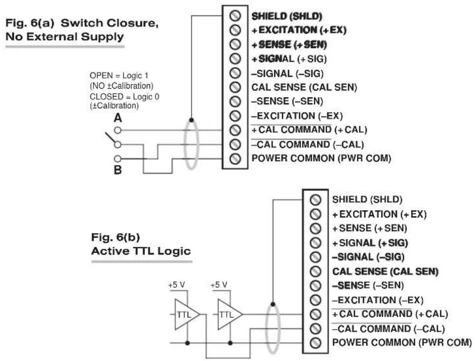
NOTE: Per-channel shunt calibration for the AA72 can be "remotely" controlled, if desired, as an alternative to using the software "SHUNT CALIBRATE" commands provided by the system. This remote calibration control is accomplished by means of logic-level inputs to the AA72 card. The relevant connections are given in Fig. 6.
Fig. 6(a) shows how the “CALIBRATE POSITIVE” and “CALIBRATE NEGATIVE” commands can be independently applied to any active AA72 channel, without the need of an external logic reference supply.
Closing the switch in Fig. 6(a) to contact point "A" will produce a Logic 0 level at the "NOT +CAL COMMAND" terminal. Since this is a negative-true logic line, the Logic 0 input will activate the "+CALIBRATE" condition of the channel. That is, it will switch in the channel's shunt resistor for a positive up-scale reading. Opening the switch to disconnect the "NOT +CALIBRATE" line from POWER COMMON will then return the channel to the "NO +CALIBRATE" condition.
Similarly, closing the switch to contact point "B" will produce a Logic 0 level at the "NOT -CAL COMMAND" terminal, thereby switching in the channel's shunt resistor for a negative up-scale reading. Opening the switch to disconnect the "NOT -CALIBRATE" line from POWER COMMON will then return the channel to the "NO -CALIBRATE" condition.
You may also use active TTL logic, as illustrated in Fig. 6(b), to produce the “+CALIBRATE” or “-CALIBRATE” condition for either AA72 channel.
Fig. 6 Logic Inputs for AA72 Remote Shunt Calibration
text_image
Fig. 6(a) Switch Closure, No External Supply OPEN = Logic 1 (NO ±Calibration) CLOSED = Logic 0 (±Calibration) A B SHIELD (SHLD) + EXCITATION (+EX) + SENSE (+SEN) + SIGNAL (+SIG) -SIGNAL (-SIG) CAL SENSE (CAL SEN) -SENSE (-SEN) -EXCITATION (-EX) + CAL COMMAND (+ CAL) -CAL COMMAND (-CAL) POWER COMMON (PWR COM) Fig. 6(b) Active TTL Logic +5 V TTL +5 V SHIELD (SHLD) + EXCITATION (+EX) + SENSE (+SEN) + SIGNAL (+SIG) -SIGNAL (-SIG) CAL SENSE (CAL SEN) -SENSE (-SEN) -EXCITATION (-EX) + CAL COMMAND (+ CAL) -CAL COMMAND (-CAL) POWER COMMON (PWR COM)4 OPTIONAL BRIDGE COMPLETION: MODEL 10CJB-2 DUAL BRIDGE COMPLETION CARD
4.a PURPOSE
The optional Model 10CJB-2 Dual Bridge Completion Card lets you connect each of your Model AA72's inputs to a 2-wire 1/4-bridge, 3-wire 1/4-bridge, 1/2-bridge, or full-bridge strain gage configuration.* Each 1/4-bridge configuration may use either 120 or 350 ohms nominal gage resistance. The function of the Model 10CJB-2 is to "complete" the connected bridge—that is, to allow it to be "seen" by the Model AA72 as a full (4-arm) Wheatstone bridge.
For calibration of AA72 channels originating from the Model 10CJB-2, see Section 4.c, below.
4.b 10CJB-2 TRANSDUCER CONNECTIONS
Remove the top plate of the Model 10CJB-2 box (4 screws in corners). Inside the box are two sets of labelled screw terminals, one for each of the AA72's input channels ("A" and "B"). As shown in the following figures, you will connect your gage wires directly to these terminals, and, if necessary, interconnect certain terminal pairs by means of jumper wires. Gage leads should enter the 10CJB-2 through the cutout on the right-hand side of the box.
NOTE: A SPECIAL DAYTRONIC CABLE MUST BE USED TO CONNECT THE 10CJB-2 TO THE AA72'S REAR I/O CONNECTOR. Contact the Daytronic Service Department for full details.
Fig. 7(a) shows connections between the 10CJB-2 and a 2-wire 1/4-bridge gage configuration (represented by the single gage resistor). Here, you must install a jumper wire between the -SIG and 1/2 BR terminals, and between the +SIG terminal and either the 120 terminal or the 350 terminal, depending on the nominal gage resistance.
Fig. 7(b) shows connections between the 10CJB-2 and a 3-wire 1/4-bridge gage configuration (again represented by the single gage resistor). Here again, the -SIG and 1/2 BR terminals must be tied. The gage's third (self-compensating) lead is connected either to the 120 terminal or to the 350 terminal, depending on the nominal gage resistance.
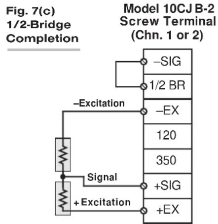
Fig. 7(c) shows connections between the 10CJB-2 and a 1/2-bridge gage configuration (represented by the two connected gage resistors). Here again, the -SIG and 1/2 BR terminals must be tied.
Fig. 7(d) shows connections between the 10CJB-2 and a full-bridge gage configuration (represented by the four connected gage resistors).
Fig. 7 Model 10CJB-2 Transducer Cabling
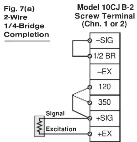
text_image
Fig. 7(a) 2-Wire 1/4-Bridge Completion Model 10CJ B-2 Screw Terminal (Chn. 1 or 2) -SIG 1/2 BR -EX 120 350 +SIG +EX Signal Excitation
flowchart
graph TD
    A["Signal"] --> B["Excitation"]
    B --> C["-SIG"]
    B --> D["1/2 BR"]
    B --> E["-EX"]
    B --> F["120"]
    B --> G["350"]
    B --> H["+SIG"]
    B --> I["+EX"]
    J["Model 10CJ B-2 Screw Terminal (Chn. 1 or 2)"]
text_image
Fig. 7(c) 1/2-Bridge Completion Model 10CJ B-2 Screw Terminal (Chn. 1 or 2) -Excitation -SIG 1/2 BR -EX 120 350 +SIG +EX Signal + Excitation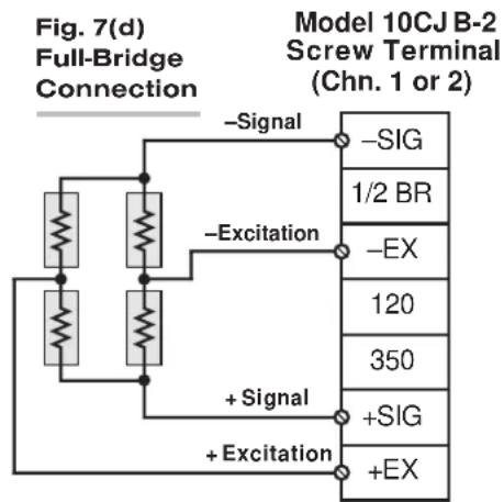
text_image
Fig. 7(d) Full-Bridge Connection Model 10CJ B-2 Screw Terminal (Chn. 1 or 2) -Signal -Excitation +Signal +Excitation -SIG 1/2 BR -EX 120 350 +SIG +EX4.c CALIBRATION
CALCULATED CALIBRATION
You can calibrate an AA72 channel receiving strain-gage input from a Model 10CJB-2 Bridge Completion Card by applying the MV/V CALIBRATION (MVV) command as described in Section 3.d, above. Note however that, in this case,
- for "i" (the transducer sensitivity rating), you should enter one of the following full-scale "mV/V" values, whichever corresponds to the channel's "type" setting (see Table 1): 0.75 (for "Type 70"), 1.50 (for "Type 71"), or 3.00 (for "Type 72").
- for "u" (the nominal full-scale rating), you should enter the full-scale microstrain range that corresponds to the selected transducer sensitivity rating, as given in the following table:
Table 6 Strain Gage Microstrain Ranges (AA72)
Full-Scale Full-Scale
Output (mV/V) Microstrain Range
| 0.75 u = 3000 / (N · G) |
| 1.50 u = 6000 / (N · G) |
| 3.00 u = 12000 / (N · G) |
Here, "N" is the number of active strain-gage arms in the gage configuration. Thus, for a 1/4-bridge gage, N = 1; for a half-bridge gage, N = 2; and for a full-bridge gage, N = 4. "G" is the gage factor of the strain gage, and is normally provided by the manufacturer.
TWO-POINT (DEADWEIGHT) CALIBRATION
See Section 3.d, above, for the general procedure. Your first calibration point (entered via the ZERO (ZRO) command) should be zero. Your second calibration point (entered via the FORCE (FRC) command) should be expressed in microstrain (microinches/inch).
SIMULATED (SHUNT) CALIBRATION
See Section 3.d, above, for the general procedure. Your EQUIVALENT INPUT value, which is entered via the FORCE (FRC) command—following zeroing of the channel and switching in of the shunt resistor)—should be expressed in microstrain (microinches/inch).
Coarse Zero Offset
In the event that, during "Two-Point" or "Simulated" calibration of the 10CJB-2 channel, you are unable to set the desired span via the FORCE (FRC) command, you can apply a positive or negative zero offset of approximately 1 mV/V for balance correction, as follows:
- Remove the top plate of the 10CJB-2 box and locate the three programming jumper pads for the channel in question. Labelled "A" for Channel 1 and "B" for Channel 2, the pads are near the left edge of the 10CJB-2 circuit board.
- Place a solder drop between the center pad and either the "+" or "-" pad, depending on the desired offset polarity.
- Re-enter your ZRO and FRC values (with or without calibration "shunt").
5 DIAGNOSTIC WIRE-WRAP PINS
As a special diagnostic and service tool, the five pins shown in Fig. 8 are directly accessible from the front of an installed AA72 card. These pins allow voltmeter or oscilloscope observation of data-channel output signals. THEIR USE IS INTENDED PRIMARILY FOR TRAINED SERVICE TECHNICIANS. With regard to the on-board diagnostic pins, please note the following:
- PROPER ESD PRACTICE SHOULD BE OBSERVED WHEN MAKING CONTACT WITH AN AA72 BOARD INSTALLED IN A "LIVE" DAYTRONIC SYSTEM MAINFRAME. ALWAYS GROUND YOURSELF TO THE MAINFRAME CHASSIS BEFORE TOUCHING THE BOARD.
- THE ANALOG SIGNAL PRESENT AT EACH ACTIVE "CHANNEL" PIN REPRESENTS EIGHT TENTHS (0.8) OF THAT CHANNEL'S NOMINAL CALL-BUS VOLTAGE. For a channel delivering a standard full-scale (+5-V) output, the corresponding diagnostic pin will therefore register +4 V.
- THE ANALOG SIGNAL PRESENT AT EACH ACTIVE "CHANNEL" PIN REPRESENTS THE FILTERED CHANNEL OUTPUT, AND IS NOT AFFECTED BY THE ANALOG OUTPUT MODE CURRENTLY SELECTED FOR THAT CHANNEL (see Section 3.c).
- THE "SLOT CALL" PIN DELIVERS A LOGIC SIGNAL THAT MAY BE USED TO SYNCHRONIZE AN OSCILLOSCOPE FOR TIMING ANALYSIS OF THE AA72 CARD.
- THE "CHANNEL 3" AND "CHANNEL 4" PINS ARE ONLY ACTIVE FOR AN AA72-4 CARD.
Fig. 8 Diagnostic Wire-Wrap Pins
