Performance HRVCRSVU - Air-conditioner CARRIER - Free user manual and instructions
Find the device manual for free Performance HRVCRSVU CARRIER in PDF.

User questions about Performance HRVCRSVU CARRIER
0 question about this device. Answer the ones you know or ask your own.
Ask a new question about this device
Download the instructions for your Air-conditioner in PDF format for free! Find your manual Performance HRVCRSVU - CARRIER and take your electronic device back in hand. On this page are published all the documents necessary for the use of your device. Performance HRVCRSVU by CARRIER.
USER MANUAL Performance HRVCRSVU CARRIER
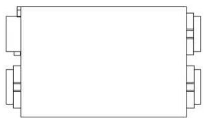
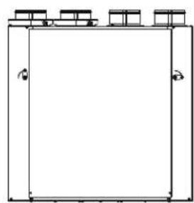
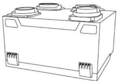
ERVCRLHB, ERVCRSHB, ERVCRSVB, HRVCRLHB, HRVCRSVU, HRVCRSHB, HRVCRSVB
Energy Recovery Ventilators & Heat Recovery Ventilators
Owner's Manual
natural_image
Simple line drawing of a rectangular object with four corner blocks, no text or symbols present.HRVCRLHB, ERVCRLHB
natural_image
Simple line drawing of a rectangular frame with three small boxes on top (no text or symbols)HRVCRSVU
natural_image
Line drawing of a rectangular electronic component with two circular ports and mounting brackets (no text or symbols)HRVCRSVB, ERVCRSVB

natural_image
Line drawing of a rectangular electronic device with mounting holes and internal components (no text or symbols)HRVCRSHB, ERVCRSHB
A12308ALT
Fig. 1 - Heat Recovery Ventilators
NOTE TO EQUIPMENT OWNER:
For your convenience, please record the model and serial numbers of your new equipment in the spaces provided. This information, along with the installation data and dealer contact information will be helpful should your system require maintenance or service.
VENTILATOR
Model # ____
Serial #
ACCESSORIES (List type and model #)
INSTALLATION INFORMATION:
Date Installed
DEALERSHIP CONTACT INFORMATION:
Company Name
Address
Phone Number
Technician Name
NOTE TO INSTALLER:
This manual must be left with the equipment owner.
PURPOSE OF THE VENTILATION SYSTEM
Your ventilation system is designed to provide fresh air to your home while exhausting stale air from your home. By eliminating accumulated pollutants and humidity, it maintains an optimum air quality and an ideal relative humidity.

natural_image
Technical line drawing of an industrial facility interior with pipes and ventilation ducts (no text or symbols)Fig. 2 - Typical Installation
NOTES:
- Typical installation shown with a forced air system, which can also operate on its own.
- Installation may vary according to the model number and the position (normal or reverse) in which the unit is installed.
HEAT RECOVERY
Your ventilation system is equipped with a heat recovery core that is designed specifically to control excess humidity and reduce ventilation costs by recovering the heat energy from the exhausted air, and using that same heat energy to warm the fresh air being supplied. This heat recovery process is accomplished in such a way that the stale air is never mixed with the fresh air.

text_image
EXAMPLE Stale air to outside Fresh air to building OUTSIDE INSIDE Fresh air from outside Stale air from building A12309Fig. 3 - Heat Recovery Process
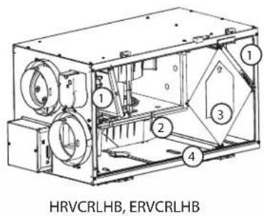
Internal Components
Unit shown in normal position Can also be installed upside down. Position of components varies by model.
text_image
HRVCRLHB, ERVCRLHB
text_image
1 2 3 4 5 6 7 8 ERVCRSHB
text_image
HRVCRSHB
text_image
1 2 3 4 HRVCRSVUA180114
Fig. 4 - Component Identification
- Filters
- Blower
- HRV or ERV core
- Condensation tray
- Fresh air supply
- Stale air return
- Exhaust air
- Electronic control circuit
SAFETY CONSIDERATIONS
Recognize safety information. This is the safety-alert symbol When you see this symbol on the unit and in instructions or manuals, be alert to the potential for personal injury. Understand these signal words; DANGER, WARNING, and CAUTION. These words are used with the safety-alert symbol. DANGER identifies the most serious hazards which will result in severe personal injury or death. WARNING signifies hazards which could result in personal injury or death. CAUTION is used to identify unsafe practices which would result in minor personal injury or product and property damage. NOTE is used to highlight suggestions which will result in enhanced installation, reliability, or operation.

WARNING
Failure to follow this warning could result in personal injury or death.
Before servicing system, always turn off main power to system. Turn off accessory heater power if applicable. There may be more than 1 disconnect switch.

CAUTION
CUT HAZARD
Failure to follow this caution may result in personal injury.
Although special care has been taken to minimize sharp edges in the construction of your unit, be extremely careful when handling parts or reaching into the unit. Wear appropriate protective clothing and gloves when working on this unit.
IMPORTANT:
Some activities create dust or vapors which may damage your unit. You must therefore turn off and unplug your unit in the following situations:
•Major renovation work
• Sanding (e.g. gypsum joints, etc.)
•Housing construction
•Varnishing
During very heavy snowstorms or rain with strong winds, the unit should also be turned off to avoid problems caused by snow or rain entering the unit, even if it is equipped with an anti-gust intake hood.
CONTROLS
Integrated Control
All units are equipped with an integrated control, located on the electrical compartment. Use the push-button (1) to control the unit. The LED (2) will then show on which mode the unit is in.
NOTES:
- The integrated control must be turned OFF to use an optional main control.
- If an optional auxiliary control is used, if activated, this auxiliary control will override the optional main control.
Refer to table below to see how to operate the unit using its integrated control.
PRESS ON PUSH BUTTON
Once Amber
Twice Green
Three Times No Light
LED COLOR RESULTS
Unit is on Low Speed
Unit is on High Speed
Unit is OFF
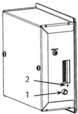
text_image
Technical diagram of a device casing with labeled components 1 and 2, showing internal structure and mounting points.
text_image
1 2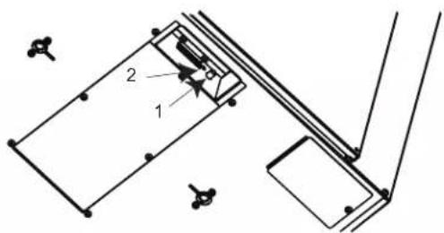
text_image
Technical diagram showing a mechanical assembly with labeled components 1 and 2, likely for engineering or manufacturing documentation.Bottom of the unit
A12296ALT, A07260, A11210
Fig. 5 - Integrated Control
Boot Sequence of Integrated Control
The unit boot sequence is similar to a personal computer boot sequence. Each time the unit is plugged after being unplugged, or after a power failure, the unit will perform a 30-second booting sequence before starting to operate. During the booting sequence, the integrated control LED will light GREEN (unit set in normal defrost) or AMBER (unit set in extended defrost) for 5 seconds, and then will shut off for 2 seconds. After that, the LED will light RED for the rest of the booting sequence. During this RED light phase, the unit is checking and resetting the motorized damper position. Once the motorized damper position completely set, the RED light turns off and the booting sequence is done.
NOTE: No command will be taken until the unit is fully booted.
Defrost Mode
When the outside temperature is below -5^ ( 23^ ), heat recovery creates frost in the module. To maintain its proper operation, the unit is programmed to defrost the recovery module. The defrost frequency varies according to the outside temperature. Defrost lasts 6–10 minutes (or 10 minutes if set on “Extended Defrost”). During the defrost cycle, the unit shifts to maximum speed and the dampers close.
After defrosting, the unit returns to the operating mode selected by the user.
Wall Controls

# DESCRIPTION
1 Standard HRV Control
2 Latent Wall Control
3 OneTouch Control
4 Basic Wall Control
5 Optional: Auxiliary 20—Minute Push Button Timer
6 (not shown) Optional: Auxiliary 60—Minute Crank Timer
WHERE USED
Used with HRVs
Used with ERVs
Used with ERVs and HRVs as a main wall control
Used with HRVs
Used with ERVs and HRVs when 20 minute manual operation is required
Used with ERVs and HRVs
20-Minute Lighted Push-Button
Press once to activate the push-button. The unit will operate on high speed for 20 minutes and the indicator will light up. To stop activation before the end of the 20-minute cycle, push one more time.
One-Touch Control
Activate the push-button. The color of the indicator shows the unit operating mode.
High - This mode is recommended for the removal of excess pollutants and humidity. The ventilator will operate at its maximum speed continuously. The power indicator light will be lit red when this mode is selected.
Low - This mode is recommended for normal daily operation. The ventilator will operate at its minimum speed continuously. The power indicator light will be lit yellow when this mode is selected.
Intermittent - This mode is recommended when the inside air is too dry in the heating season or too humid in the cooling season. The ventilator will operate at its minimum speed for 20 minutes per hour and be off for 40 minutes per hour. The power indicator light will be lit green when this mode is selected.
Off - To turn the ventilator off, press "Push" until the power indicator light is turned off.
Dehumidistat Control
Adjusting DEHUMIDISTAT (standard control)
Setting during summer months:
During this period, unless being afflicted with breathing problems, using the Dehumidistat is unnecessary. Set the slide switch to "OFF". (Do not exchange in day time; exchange at night time, if cool outside, or if it is not raining.)
Setting during fall, winter and spring months:
(When severe condensation appears on windows.)
-
Determine the humidity level in your house (bring the knob (B) counterclockwise to its maximum position, then bring it back clockwise slowly until you hear a "click").
-
Set the knob to one line under this temperature level or "click".
IMPORTANT: Do not select a temperature below -20^ ( -4^ ). This could lead to excessive dryness in the air causing discomfort for the occupants.
It is possible (and normal) to experience condensation on your windows when drastic changes in temperature happen (for example: -5^ [23^] to -20^ [-4^] ). In that case, we suggest waiting a few days to allow the situation to stabilize.
Recommended Humidity Levels (Heating Operation)
In order to prevent condensation on interior windows, do not exceed humidity levels shown on table.
| OUTSIDE TEMPERATURE | DOUBLE-PANE WINDOWS | TRIPLE-PANE WINDOWS |
| 50^ / 10^ | 55% | 65% |
| 32^ / 0^ | 45% | 55% |
| 14^ / -10^ | 35% | 45% |
| -4^ / -20^ | 30% | 45% |
| -22^ / -30^ | 25% | 35% |
Adjusting DEHUMIDISTAT with Latent Control (ERV only)
- Low Exchange Mode — If the relative humidity inside the building is lower than selected, air exchange would occur with the outside at high speed. If the relative humidity level inside the building is higher than selected, air exchange would occur outside at low speed. This ensures continuous air exchange for constant air quality.
- Intermittent Mode — If the relative humidity inside the building is higher than selected, no air exchange would occur, and the system would turn off. If the relative humidity inside the building is lower than selected, air exchange would occur with outside at high speed. This mode is ideal for maintaining the proper humidity level when the continuous mode cannot.
Table 1 – Basic Control
| MODE OPERATION | DAMPER POSITION | FAN SPEED |
| Off Off Closed to outside Off | ||
| Low Air exchange with outside Open to outside Low | ||
| High Air exchange with outside Open to outside High |
Table 2 – OneTouch Push Button Control
| MODE OPERATION | DAMPER POSITION | FAN SPEED | |
| Off Off Closed to outside Off | |||
| Low | Air exchange with outside | Open to outside Low | |
| Intermittent | |||
| 40 min off | Air exchange with outside | Open to outside 20 min | Low |
| 20 min exchange low speed | Closed 40 min | Off | |
| High | Air exchange with outside | Open to outside High | |
Table 3 – Compatible Optional Auxiliary Wall Controls
DEHUMIDISTAT
20-minute lighted push-button switch (5 max.)
Table 4 – Standard Control (HRV)
| MODE | DEHUMIDISTAT POSITION | OPERATION | DAMPER POSITION | FAN SPEED ON LED | AIR EXCHANGE LED | |
| Off Any Off Closed to outside Off Off Off | ||||||
| Low | SatisfiedCall for dehumidification High | Air exchange with outside | Open to outside On | Low | On | |
| Intermittent 40 min off20 min | Satisfied | Off 40minLow 20 min | Closed to outside/open | Off/Low | On | Off |
| exchange low speed | Call for dehumidification | Air exchange with outside | Open to outside | High | On | |
Table 5 – Latent Control (ERV)
| MODE | DEHUMIDISTAT POSITION | OPERATION | DAMPER POSITION | FAN SPEED ON LED | AIR EXCHANGE LED | |
| Off Any Off Closed to outside Off Off Off | ||||||
| Low | SatisfiedCall for dehumidification | Air exchange with outside | Open to outside | HighLow | OnOn | |
| Intermittent 40 min off 20 min | Satisfied | Air exchange with outside | Open to outside | High | On | On |
| exchange low speed | Call for dehumidification | Off 40minLow 20 min | Closed to outside/open | Off/Low | Off | |
MAINTENANCE

WARNING
Failure to follow this warning could result in personal injury or death.
Before servicing system, always turn off main power to system. Turn off accessory heater power if applicable. There may be more than 1 disconnect switch.
IMPORTANT: When cleaning the unit, it is recommended to wear safety glasses and gloves.

CAUTION
CUT HAZARD
Failure to follow this caution may result in personal injury.
Although special care has been taken to minimize sharp edges in the construction of your unit, be extremely careful when handling parts or reaching into the unit. Wear appropriate protective clothing and gloves when working on this unit.
Every Three Months
Regular maintenance should be performed every 3 months. Annual maintenance should take place every fall season.
- Disconnect power supply.
- Unlatch the door.
-
Clean the inside of the door with a damp cloth.
-
Clean filters:
-
Remove filters.
•Vacuum to remove most of the dust. -
Wash with a mixture of warm water and mild soap. You may add bleach if you wish to disinfect (one tablespoon per gallon). Rinse thoroughly. Shake filters to remove excess water and let dry.
-
Clean the condensation tray with a damp cloth.
-
Check the exterior air intake hood:
-
Make sure there are no leaves, twigs, ice or snow that could be drawn into the vent.
- Clean if necessary.
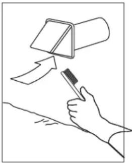
natural_image
Line drawing of a hand holding a tool with an arrow pointing to a cylindrical object (no text or symbols)A12317
Fig. 6 - Exterior Air Intake Hood
IMPORTANT: Even a partial blocking of this air vent could cause the unit to malfunction.
- Reassemble the components.
- Reconnect power supply.
Annual Maintenance (Fall)
Repeat steps 1 to 6 from previous Section and continue with the following steps:
IMPORTANT: Handle the heat recovery core with care.
- Clean the heat recovery core:
NOTE: These steps are for the HRV ONLY. Do NOT soak an ERV core. Damage will occur.
- Remove core.
- Let it soak in a mixture of cold or lukewarm water and mild soap (dish washing liquid).
- Rinse thoroughly.
-
Shake the core to remove excess water and let it dry.
-
Clean blower assembly.
- Remove dust using a vacuum cleaner with a soft brush attachment.
- Reassemble the components.
- Reconnect power supply.
BEFORE YOU CALL FOR SERVICE
- Check the main power disconnect switch. Verify that the circuit breakers are ON or that fuses have not blown. If you must reset breakers or replace fuses, do so only once. Contact your servicing dealer for assistance if the breakers trip or the fuses blow a second time.
- Check for sufficient airflow. Check air filters for accumulations of large particles. Check for blocked exhaust–air grilles or ductwork. Keep grilles and duct work open and unobstructed.
- If the condensate fails to drain properly, check the grommet and drain tube for obstructions. Make sure that the condensate drain tube has a slight slope and is not kinked.
If your unit still fails to operate properly, contact your servicing dealer. Provide your model and serial number. With this information, the dealer will be able to correct any problems.
Replacement Parts and Repairs
In order to ensure your ventilation unit remains in good working condition, you must use genuine replacement parts only. The genuine replacement parts are specially designed for each unit and are manufactured to comply with all the applicable certification standards and maintain a high standard of safety. Any third party replacement part used may cause serious damage and drastically reduce the performance level of your unit, which will result in premature failing.
TROUBLESHOOTING
PROBLEM YOU SHOULD TRY THIS
- Nothing works.
- Noisy unit.
- Condensation on windows (air too humid).
- Air too dry.
- Air too cold at the air supply grille.
• See if the unit is plugged in.
- See if the unit is receiving power from the house circuit breaker or fuse.
- Clean the unit. If the problem is not solved, contact your installer.
- Adjust the humidity control knob as per instructions.
- Operate the unit at maximum speed (MAX.) during activities generating excess humidity (family gatherings, extra cooking, etc.)
- Leave curtains half-open to allow air circulation.
- Store all firewood in a closed room with a dehumidifier or in a well ventilated room, or store the wood outside.
- Keep the temperature in your house above 18^ (64°F).
- Do not adjust your humidity control below -20^ (30°F).
- Operate the unit at low speed (MIN.)
•Temporarily switch to the intermittent mode.
•Temporarily use a humidifier.
- Make sure the outside hoods are not blocked.
- Operate the unit at low speed (MIN.).
- Have the system's balancing checked.
- Have the unit's defrost system checked.
• Install a duct heater.