
BMS-CT1280UL - Air-conditioner CARRIER - Free user manual and instructions
Find the device manual for free BMS-CT1280UL CARRIER in PDF.


| Product Type | Split-System Air Conditioner |
| Model | BMS-CT1280UL |
| Brand | Carrier |
| Cooling Capacity | 12,000 BTU |
| Heating Capacity | 12,000 BTU (Heat Pump) |
| Power Supply | 230V / 60Hz |
| Phase | Single Phase |
| Refrigerant | R-410A |
| SEER Rating | 14.5 |
| Indoor Unit Dimensions (WxHxD) | 38.5 x 11.8 x 8.7 inches |
| Outdoor Unit Dimensions (WxHxD) | 28.3 x 23.6 x 12.6 inches |
| Net Weight (Indoor) | 22 lbs |
| Net Weight (Outdoor) | 66 lbs |
| Airflow (High) | 400 CFM |
| Noise Level (Indoor) | 26 - 42 dB |
| Noise Level (Outdoor) | 52 dB |
| Functions | Cool, Heat, Dry, Fan, Auto, Sleep, Turbo, Timer |
| Remote Control | Included |
| Filter Type | Washable / Anti-Dust |
| Installation Type | Wall Mounted |
| Energy Star | Yes |
| Refrigerant Lines | 1/4" Liquid, 3/8" Suction |
Frequently Asked Questions - BMS-CT1280UL CARRIER
User questions about BMS-CT1280UL CARRIER
0 question about this device. Answer the ones you know or ask your own.
Ask a new question about this device
Download the instructions for your Air-conditioner in PDF format for free! Find your manual BMS-CT1280UL - CARRIER and take your electronic device back in hand. On this page are published all the documents necessary for the use of your device. BMS-CT1280UL by CARRIER.
USER MANUAL BMS-CT1280UL CARRIER
Safety Precautions 3
1 Product Overview .... 5
2 System Configuration 36
3 Initial Settings 38
4 Troubleshooting 52
5 Service Parts 55
Installation Manual
Network Configuration Guide
Owner's Manual
Safety Precautions
- This section explains safety precautions you must follow in order to prevent harm to the user and other persons and damage to property.
- "Display Description" explains the classification of the degree of harm or damage that may occur if the unit is handled incorrectly, while "Symbol Description" indicates the meanings of symbols.
Display Description Symbol Description
 | WARNING | Indicates "Content that is expected to result in death or serious injury (*1) to the user in the case of incorrect handling". |  | indicates prohibited actions. Specifically prohibited contents are indicated with a picture and/or text in or near the symbol. |
 | CAUTION | Indicates "Content that is expected to result in minor injury (*2) to the user or damage to property (*3) in the case of incorrect handling". |  | indicates instructions which must be followed. The actual contents of the instructions are indicated with a picture and/or text in or near the symbol. |
WARNING
CAUTION
* 1: Serious injury refers to lasting after effects such as blindness, injury, burns (high temperature / low temperature), electric shock, bone fracture, or poisoning, etc. and injuries that require hospitalization/long-term outpatient treatment.
* 2: Minor injury refers to injuries, burns, or electric shocks, etc. that do not require hospitalization or long-term outpatient treatment.
* 3: Damage to property refers to extended damage related to houses, household goods, livestock, or pets, etc.

DANGER
 Turning off the circuit-breaker Turning off the circuit-breaker | • Set the circuit-breaker to "OFF" before starting workFailing to do so may result in a high-voltage electric shock, leading to death or injury. |
 Prohibited Prohibited | • Do not turn on the circuit-breaker when the cover is removedDoing so may result in a high-voltage electric shock leading to death or injury. |

WARNING
 Check earth connection Check earth connection | · Check that the earth wire (*) is connected to the unit earth terminal before beginning troubleshooting and repair workIf the earth wire is not connected, there is the risk of electric shock in the event of an electric leakage occurring. |
 Modification prohibited Modification prohibited | · Do not modify the productAlso, do not disassemble or modify the parts.Doing so may cause fire, electric shock, or injury. |
 Children must be kept away Children must be kept away | · Only qualified engineers should be allowed on a troubleshooting or repair work site. Children and all other third parties must be kept awayThere is a risk of injury from tools or disassembled parts.Inform the customer that children and other third parties must be kept away from the work site. |
 Insulation Insulation | · After connecting a crimp terminal to a cut lead wire, place the closed-end facing up and clean itIf connections are not properly processed, electrical leakage, ignition or other accident could occur on the customer's premises. |
 Wiring PrecautionsDuring Assembly Wiring PrecautionsDuring Assembly | · After repairs are complete, be sure to reassemble the disassembled parts and connect and route the wires to restore the equipment to its original state. Make sure internal wires are not trapped in the cabinets, panels, or other partsAn assembly or wire connection problem may result in a short circuit, ignition or other accident on the customer's premises. |
 Risk of electric shock Risk of electric shock | ·If you have to inspect a circuit that is energized, for example, take precautions such as wearing rubber gloves to avoid direct contact with a live partTouching a live part may result in an electric shock. |
 Check after repair Check after repair | ·Check that there are no abnormalities after completing the repair workFailure to perform this check may result in fire, electric shock, or injury.Turn off the earth leakage breaker before performing an inspection. |
| ·After completing the repair work, perform a test run and check that there are no abnormalities such as smoke or unusual noiseFailure to perform this check may result in fire or electric shock.Perform a test run after installing the front panel and cabinets. | |
 Repair and reinstallation work Repair and reinstallation work | ·Installation and reinstallation work should be performed by your vendor or a qualified electricianAttempting to carry out installation work on your own, and doing so incorrectly, may result in electric shock or fire. |
1Product Overview
1-1. Function list
Specifications
Detailed specifications
| Power supply 120 V AC 60 Hz | |
| Operating temperature/humidity range | 32 to 104°F (0°C to 40°C), 10% to 90% RH (no dew condensation) |
| Dimensions: inch (mm) | H5.35"×W8.07"×D0.39" (H136 mm×W205 mm×D10 mm)(+3.15" (+80 mm))(Embedded dimensions shown in parenthesis) |
| Mass | 2.95 lb (1.34 kg) (Touch Screen Controller)0.99 lb (0.45 kg) (power adapter) |
| LCD | Type 7 TFT liquid crystal, 800×480, 16,700,000 colours(Luminance 800 cd/m2, contrast ratio 600:1) |
| Touch Screen Projection-capacitive type | |
| Communication ports | ·RS-485 port ×1(for connecting four digital I/O interfaces and four watt hour meter interfaces)·LAN port ×1 (for connecting PC) |
| USB port USB memory stick connection port ×2 | |
| External contact input 8 inputs | |
| External contact output 4 inputs | |
| Included PC software(Requires a separate PC (*1)) | ·Remote Control Software·Report Creation Software·Section Changeover Software·Data Analyzer |
*1 Conditions for PC connection (operating environment)
OS: Windows 8.1 or Windows 10
LAN port: 10BASE-T or 100BASE-TX wired LAN port
Other: mouse/keyboard, printer (if printing is required)
Function list
| Key Features | |
| Control | ON/OFF |
| Setting mode | |
| Set temp. | |
| Fan speed settings | |
| Swing ON | |
| Local remote controller operation lock/unlock | |
| Ventilation → ON/OFF | |
| Ventilation → Mode | |
| Ventilation → Fan speed | |
| Soft Cooling | |
| Energy saving ratio [%] | |
| Eco Temperature Shift | |
| Set temp. range limit | |
| Filter Sign Reset | |
| Monitoring | ON/OFF |
| Setting mode | |
| Set temp. | |
| Fan speed settings | |
| Swing ON | |
| Local remote controller operation lock/unlock | |
| Ventilation → ON/OFF | |
| Ventilation → Mode | |
| Ventilation → Fan speed | |
| Soft Cooling | |
| Energy saving ratio [%] | |
| Eco Temperature Shift | |
| Set temp. Range limit | |
| Outdoor temp. | |
| Power Level | |
| Return Back | |
| Power peak cut | |
| FILTER Sign | |
| Schedule | Setting unit (Per unit) |
| Setting unit: Week Schedule (per day of the week) | |
| Setting unit: Particular Timer setting (per date) | |
| Setting time (00:00 to 23:59) | |
| ON/OFF | |
| Setting mode | |
| Set temp. | |
| Local remote controller operation lock/unlock | |
| Return Back | |
| Energy saving ratio [%] | |
| Ventilation operation setting | |
| Vent. Mode | |
| Maximum number of schedules per day 64 | |
| Key Features | |||
| External input | Inputs | Main unit 8 inputs | |
| DIO interface 8 inputs x 4 units | |||
| Functions | Power pulse measurement | ||
| Demand Interlocking | |||
| Security Interlocking | |||
| Stop Interlocking | |||
| Operation Interlocking | |||
| For ON/OFF indication | |||
| For alarm indication | |||
| External output | Outputs | Main unit 4 outputs | |
| DIO interface 4 outputs x 4 units | |||
| Functions | Alarm Output Interlocking | ||
| Operation Output Interlocking | |||
| Controller Error Output Interlocking | |||
| For ON/OFF control | |||
1-2. Air conditioner control monitoring
This section explains the basic setting method for operation Start/Stop and air conditioning, the setting method for the operation schedule, and the confirmation method for the overall air conditioning system.
Start/Stop Operation
Overall air conditioning system operation method
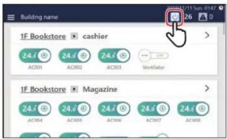
1Tap / [ICON] [ON]
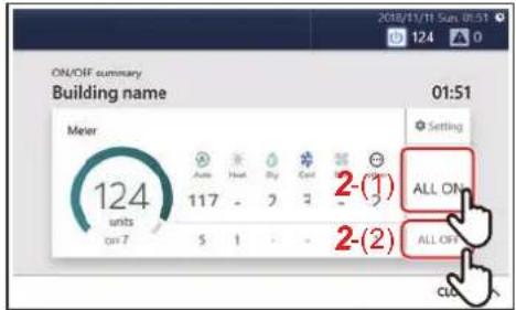
2 Tap [2-(1)] or [2-(2)]
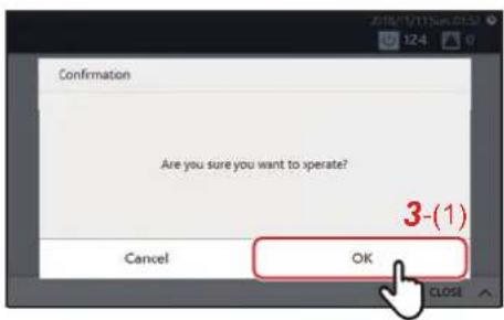
3 Check the contents of the message and tap [3-(1)]
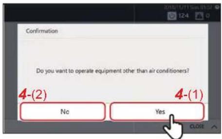
4When the screen on the left appears, check the contents of the message and tap [4-(1)] or [4-(2)] *
All air conditioners and ON/OFF unit start/stop operation.
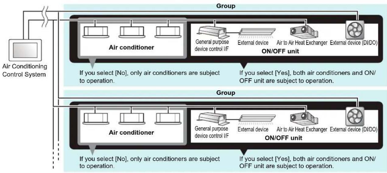
* About confirmation pop-up selection
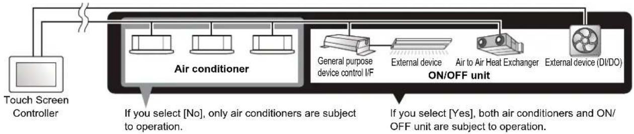
flowchart
graph LR
    A["Touch Screen Controller"] --> B["Air conditioner"]
    B --> C["General purpose device control I/F"]
    C --> D["External device"]
    D --> E["Air to Air Heat Exchanger"]
    E --> F["External device (DI/DO)"]
    B --> G["ON/OFF unit"]
    F --> G
    style A fill:#f9f,stroke:#333
    style B fill:#ccf,stroke:#333
    style C fill:#cfc,stroke:#333
    style D fill:#fcc,stroke:#333
    style E fill:#cff,stroke:#333
    style F fill:#ffc,stroke:#333
Group unit operation method
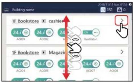
1 Scroll the home screen to display the group you want to change the settings for, then tap >
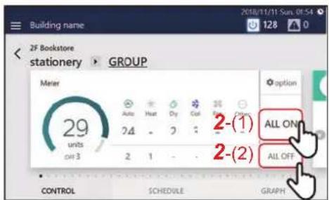
2 Tap [2-(1)] or [2-(2)]
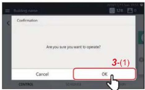
3 Check the contents of the message and tap [3-(1)]
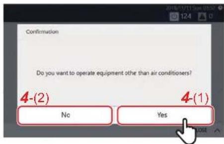
4 When the screen on the left appears, check the contents of the message and tap [4-(1)] or [4-(2)] *
All group air conditioners and ON/OFF equipment turn ON or OFF.
* About confirmation pop-up selection
flowchart
graph TD
    A["Air Conditioning Control System"] --> B["Group"]
    B --> C1["Air conditioner"]
    B --> C2["Group"]
    C1 --> D1["General purpose device control I/F"]
    C1 --> D2["External device"]
    C2 --> D3["Air to Air Heat Exchanger"]
    C2 --> D4["External device (DI/DO)"]
    B --> E1["Group"]
    E1 --> F1["Air conditioner"]
    E1 --> F2["Group"]
    F1 --> G1["General purpose device control I/F"]
    F1 --> G2["External device"]
    F2 --> G3["Air to Air Heat Exchanger"]
    F2 --> G4["External device (DI/DO)"]
    B --> H1["Group"]
    H1 --> I1["General purpose device control I/F"]
    H1 --> I2["External device"]
    H2 --> I3["Air to Air Heat Exchanger"]
    H2 --> I4["External device (DI/DO)"]
    B --> J1["Group"]
    J1 --> K1["General purpose device control I/F"]
    J1 --> K2["External device"]
    J2 --> K3["Air to Air Heat Exchanger"]
    J2 --> K4["External device (DI/DO)"]
Operation method in units of air conditioner or ON/OFF unit
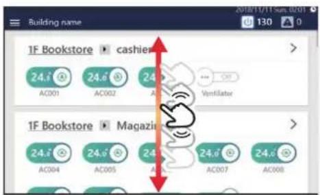
1 Scroll the home screen and display the air conditioner or ON/OFF unit that you want to change the settings for
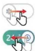

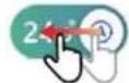

2Drag or flick the of the corresponding switch
Drag or flick to the right to start operation.
Drag or flick to the left to stop operation.
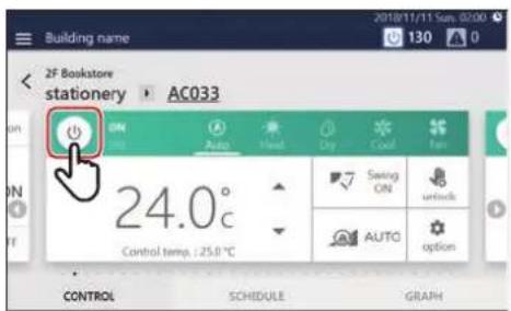
You can also start/stop operation by tapping the power icon on the [CONTROL] tab on the individual control screen displayed by tapping the switch.
* Although temperature is indicated in [°C] in the figures used in this manual, the initial temperature is displayed in [°F] on this software.
NOTE
Change the Air Conditioning Settings (ON/OFF/Mode/Wind direction/Fan Speed/Set temp.)
Group unit operation method
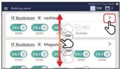
1 Scroll the home screen to display the group you want to change the settings for, then tap >
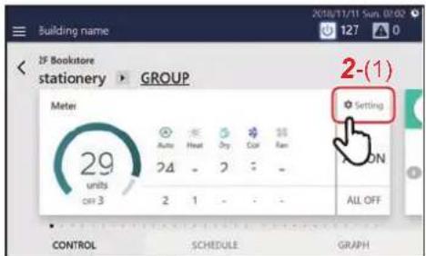
2 Tap [2-(1)] The batch settings screen is displayed.
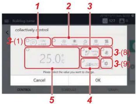
3Change settings Example: When changing the operation status settings 3-1 Tap [3-(1)] The operation status settings screen is displayed.
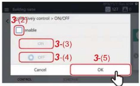
3-2 Set the check box of [3-(2)] to √
You can now change the settings.
3-3 Select [3-(3)] or [3-(4)] and tap [3-(5)]
Return to the batch settings screen.
3-4 Change the other items with reference to steps 3-1 to 3-3 For the setting details, see the following table.
| No. | Name Functions | |||||||
| 1 | ON/OFF Can be set to [ON/OFF]. | |||||||
| 2 | Mode Can be set to [Auto/Heat/Dry/Cool/Fan].NOTEA bar is displayed at the bottom of the icon for the currently selected mode.Operation modes that cannot be set are not displayed. | |||||||
| No. Name Functions | ||||||||
| 3 | Wind direction Tap to switch to the following. | |||||||
 |  |  |  |  |  |  | ||
| NOTEDepending on the connected model, items that cannot be set are not displayed. | ||||||||
| 4 | Fan Speed Tap to switch to the following. | |||||||
 |  |  |  |  |  | |||
| NOTEFor models with limited fan speed setting range, this is changed to the values that can be set for each model.Fan speeds that cannot be set are not displayed. | ||||||||
| 5 | Set temp. Tap to change the set temperature. | |||||||
| NOTEWhen set to a temperature outside the setting range limit of each operation mode, the temperature is changed to the upper or lower limit of the setting range.If there are Dual Set Point compatible models in the group, two tabs will be displayed. When you tap [3-(6)], one set temperature is displayed, and when you tap [3-(7)], two set temperatures are displayed. Tap to change the set temperature. | 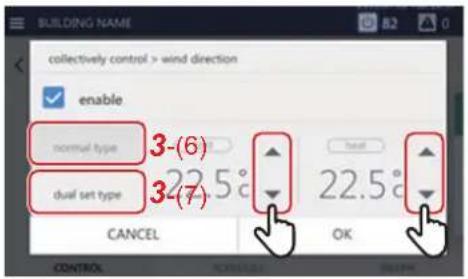 | |||||||
NOTE
- For models with limited fan speed setting range, this is changed to the values that can be set for each model.
• Fan speeds that cannot be set are not displayed.
NOTE
- For models that do not have the function set, the setting change is ignored.
- For the setting of [Lock] [Unlock] of [3-(8)], see "Local Remote Controller Lock" (Owner's Manual P.40).
- For the [Option] settings of [ 3-(9)], see "Set Operation Details" (Owner's Manual P.42).
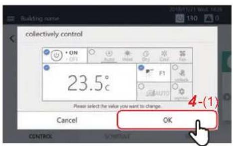
4 Confirm that the changed item is checked, and tap [4-(1)]
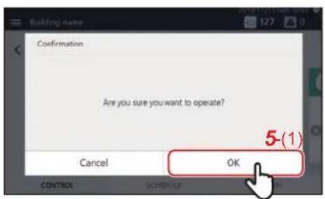
5 Check the contents of the message and tap [5-(1)]
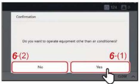
6When the screen on the left appears, check the contents of the message and tap [6-(1)] or [6-(2)] \*
The settings of the entire group are changed.
* About confirmation pop-up selection
![CARRIER BMS-CT1280UL - 6When the screen on the left appears, check the contents of the message and tap [6-(1)] or [6-(2)] \* - 1](/content/2026/05/959133/images/2db69f724ceb80995109a08b31b219108454881daf504e1afe1d835299b1aab2.jpg)
flowchart
graph TD
    A["Air Conditioning Control System"] --> B["Group"]
    B --> C1["Air conditioner"]
    B --> C2["General purpose device control I/F"]
    B --> C3["Air to Air Heat ExchangerExternal device External device"]
    C1 --> D1["Group"]
    C2 --> D1
    C3 --> D1
    D1 --> E1["If you select [No"], only air conditioners are subject to operation.]
    D1 --> E2["If you select [Yes"], both air conditioners and ON/OFF unit are subject to operation.]
    D2 --> F1["Group"]
    D2 --> F1
    D2 --> F2["Group"]
    F1 --> G1["Air conditioner"]
    F1 --> G2["General purpose device control I/F"]
    F1 --> G3["Air to Air Heat ExchangerExternal device External device"]
    G1 --> H1["Group"]
    G2 --> H1
    G3 --> H1
    H1 --> I1["If you select [No"], only air conditioners are subject to operation.]
    H1 --> I2["If you select [Yes"], both air conditioners and ON/OFF unit are subject to operation.]
Air conditioner unit operation method
NOTE
To change the settings, it is necessary to set to the operation status. (P.9)
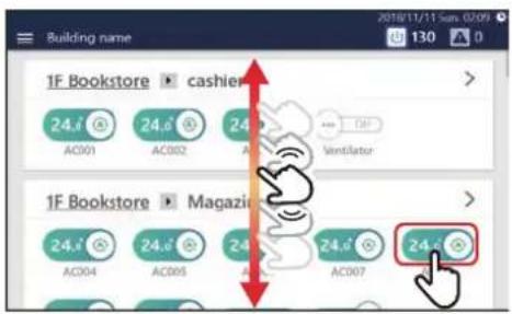
1 Scroll the home screen, display the air conditioner you want to change the settings for, then tap the switch
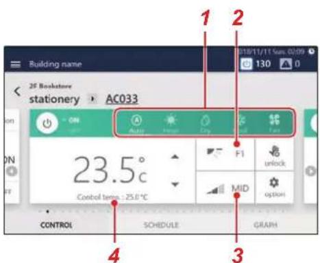
2Change settings
| No. Name Functions | ||||||||
| 1 | Mode Can be set to [Auto/Heat/Dry/Cool/Fan].NOTEA bar is displayed at the bottom of the icon for the currently selected mode.Operation modes that cannot be set are not displayed. | |||||||
| 2 | Wind direction Tap to switch to the following. | |||||||
Operation Mode Setting Range
| Auto (Cool)/Cool/Dry | Swing ON→Swing OFF→F1→F2→F3→Swing ON (Return to the beginning) |
| Auto (Heat)/Heat/Fan | Swing ON→Swing OFF→F1→F2→F3→F4→F5→Swing ON (Return to the beginning) |
NOTE
| • The setting range varies depending on the operation mode. |
| • There is a function to set only [Swing ON]. |
| No. Name Functions | |||||||
| 3 | Fan Speed Tap to switch to the following. | ||||||
| 4 | Set temp. Tap to change the set temperature. | ||||||
NOTE
- For the setting of [(1)], see "Local Remote Controller Lock" (Owner's Manual P.40).
- For the setting of [(2)], see "Set Operation Details" (Owner's Manual P.42).
- If there is no corresponding function, that item is not displayed.
Example of a model without a flap
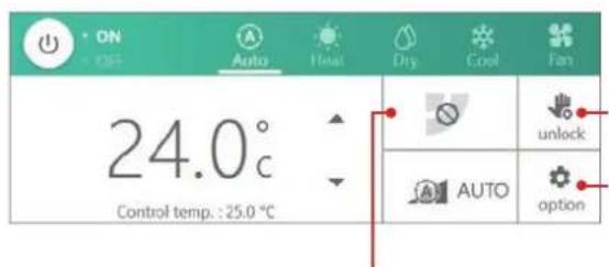
Since you cannot set the air direction, it does not change even if you tap it.
Example of a model where only a certain fan speed can be set
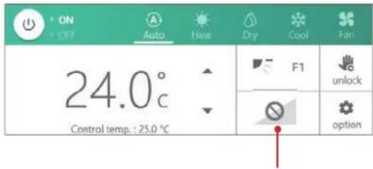
Since you cannot change the fan speed, it does not change even if you tap it.
1-3. Scheduled functions
Set the Operation Schedule
You can configure the air conditioners or the ON/OFF unit with a "Week Schedule", through which settings such as operation start/stop are changed depending on the specified time for any day from Sunday to Saturday, or a "Particular Timer setting", through which settings are changed for special days such as national holidays or special holidays. The operation schedule is set on the [SCHEDULE] tab of the group screen or individual control screen.
NOTE
If a day is set in both the Week Schedule and the Particular Timer setting, the Particular Timer setting applies and the Week Schedule is disabled for that day.
Screen description
This section explains how to view the [SCHEDULE] tab when setting the operation schedule.
NOTE
Refer to the description of the [CONTROL] tab for the display items that are not explained. (Owner's Manual P.16, 18)
Group screen
The schedule set for the air conditioners or ON/OFF unit in the group is displayed in list format in time units.
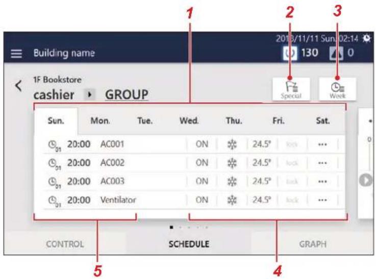
No. Functions
| 1 | You can switch the display in day-of-week units. |
| 2 | Displays the setting screen of Particular Timer setting. |
| 3 | Displays the setting screen of Week Schedule. |
| 4 | The schedule settings content (ON/OFF, Mode, Temp., Lock, more) is displayed. |
| 5 | The times when the schedule is executed and the air conditioners and ON/OFF unit for which the schedule is executed are displayed. |
Individual control screen
The schedule set for the air conditioner or ON/OFF unit being displayed is displayed on a 24-hour time scale.
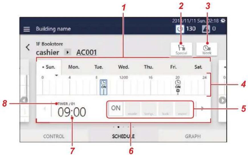
| No. Functions | |
| 1 | You can switch the display in day-of-week units. |
| 2 | Displays the setting screen of Particular Timer setting. |
| 3 | Displays the setting screen of Week Schedule. |
| 4 | is displayed at the times when the schedule is set.When operation start/stop is set, [ON] or [OFF] is displayed below. When setting change is set, is displayed below. Also, the currently displayed schedule is displayed in blue. |
| 5 | The schedule settings content (ON/OFF, Mode, Temp., Lock, more) is displayed. |
| 6 | You can switch the display to the previous or next schedule. |
| 7 | The times when the schedule will be executed are displayed. |
| 8 | The schedule setting number is displayed. |
Create a new Week Schedule
In a Week Schedule, you can set:
- Start time
• Day(s) of the week
• Air conditioner(s) or ON/OFF unit - ON/OFF
Schedule settings can be applied from either the group screen or the individual control screen. In the following procedure, the individual control screen is used to explain.
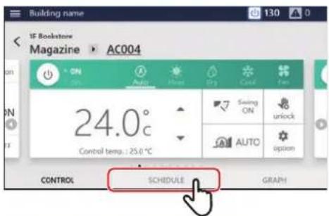
1 Tap [SCHEDULE] on the group screen or individual control screen
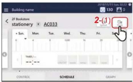
2 Tap [2-(1)]
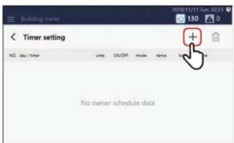
3Tap +
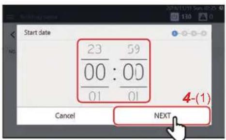
4 Tap or flick to set the start time and tap [4-(1)]
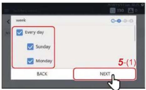
5 Select the day of the week to execute and tap [5-(1)]
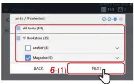
6 Select the air conditioner(s) or ON/OFF unit for setting the schedule and tap [6-(1)]
You cannot select a model that has already been scheduled at the same time.
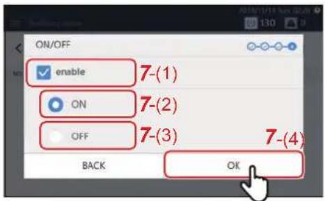
7 Tap the check box of [7-(1)] and set it to √, then select [7-(2)] or [7-(3)] and tap [7-(4)]
You can only set [ON/OFF] here.
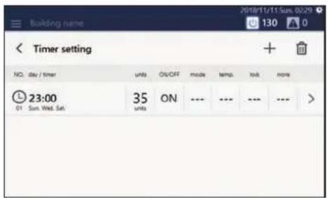
A schedule has been registered.
NOTE
- When setting details such as operation mode or set temperature, etc. as a schedule, refer to "Change the details of the Week Schedule" (P.21).
- When deleting a registered schedule, refer to "Delete the operation schedule" (P.27).
Create a new Particular Timer setting
In a Particular Timer setting, you can register special days, such as national holidays and special holidays, to configure a special schedule that differs from the Week Schedule.
Schedules can be configured from the group screen or the individual control screen. The following procedure is explained using the individual control screen.
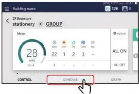
1 Tap [SCHEDULE] on the group screen or the individual control screen
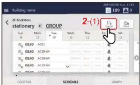
2 Tap [2-(1)]
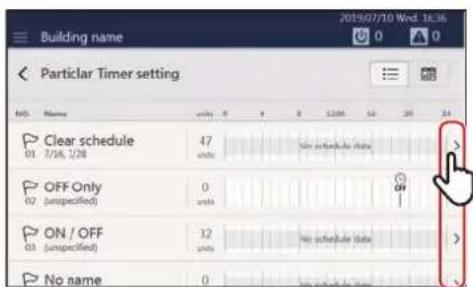
3Tap >
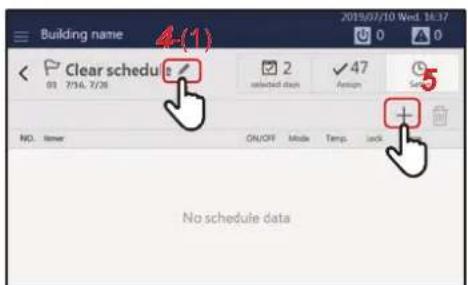
4 Tap [4-(1)] and set the schedule name A keyboard is displayed. Enter the name and then tap [4-(2)].
![1 2 3 4 5 6 7 8 9 0 - - q w e r t y u i e p [ ] a s d f g h j k l Shift z x c v b n m / Shift 4-(2) Cancel OK](/content/2026/05/959133/images/67fce48750df2d1b55663530a62e8d79790d978fd1058f71de3ac34df01be7eb.jpg)
5Tap to go to step 6
NOTE
- Tap [Shift] to toggle between upper case letters and lower case letters, and numbers and symbols.
- Tap to delete one character.
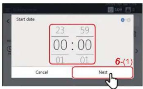
6 Tap or flick to set the start date, and then tap [6-(1)]
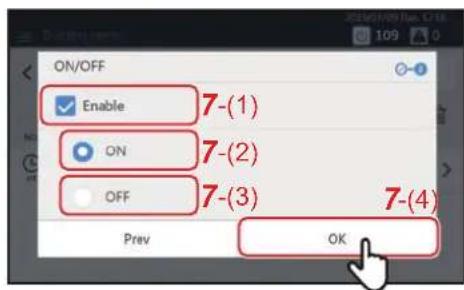
7 Tap the check box of [7-(1)] and set it to √, then select [7-(2)] or [7-(3)] and tap [7-(4)]
You can only set [ON/OFF] here.
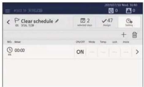
The schedule is registered.
NOTE
- When setting details such as the mode or the set temperature to a schedule, refer to "Change the details of the Particular Timer setting" (P.23).
- When deleting a registered schedule, refer to "Delete the operation schedule" (P.27).
Change the Operating Schedule
The operating schedule settings can be changed from the [Menu] button, the group screen, or the individual control screen. There are two types of operating schedules: Week Schedule and Particular Timer setting.
The following procedure is explained using the individual control screen.
NOTE
If a day is set in both the Week Schedule and the Particular Timer setting, the Particular Timer setting applies and the Week Schedule is disabled for that day.
Change the details of the Week Schedule
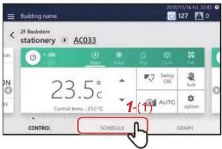
1 Tap [1-(1)] on the group screen or the individual control screen
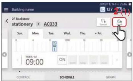
2 Tap [2-(1)]
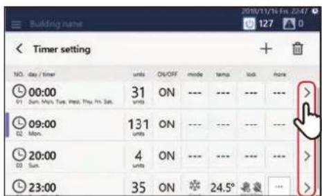
3Tap of the schedule you want to modify
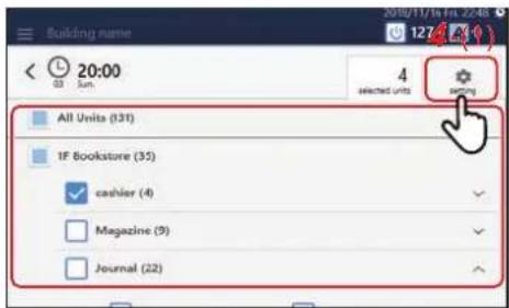
4 Modify the target air conditioner(s) or ON/OFF unit, then tap [4-(1)]
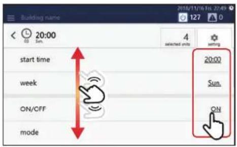
5 Scroll the screen and tap the value of the item you want to set. After changing the setting, tap [OK]
See "Setting items list" (P.25) for the items that can be configured.
Change the details of the Particular Timer setting
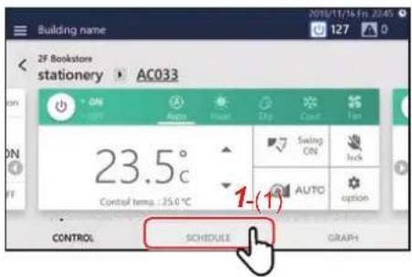
1 Tap [1-(1)] on the group screen or the individual control screen
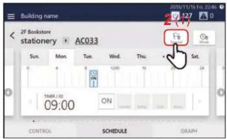
2 Tap [2-(1)]
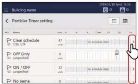
3Tap of the schedule you want to modify
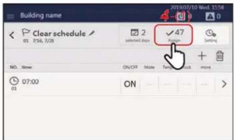
4 Tap [4-(1)] to switch to the Assign screen
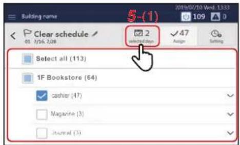
5 Modify the target air conditioner(s) or ON/OFF unit, then tap [5-(1)]
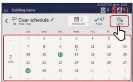
6 Tap the date you want to configure, modify the settings, and then tap [6-(1)]
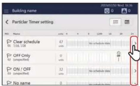
7 Tap of the schedule you want to modify
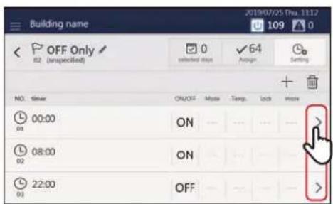
8Tap of the time you want to modify
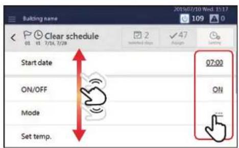
9 Scroll the screen and tap the value of the item you want to set. After changing the setting, tap [OK]
See "Setting items list" (P.25) for the items that can be configured.
Setting items list
| Setting Items Setting Procedure | |
| Time setting [Start date] | Tap or flick to change the time. |
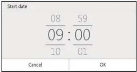 | |
| Day of the week setting [week] | Set the check box(es) of the day(s) of the week on which you want to execute the schedule to √.NOTE |
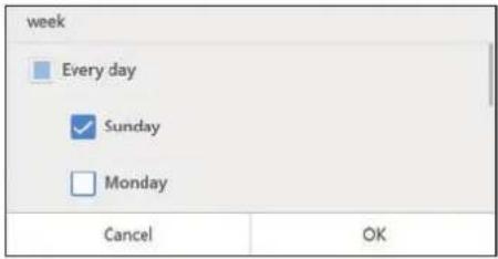 | The day of the [week] setting is not displayed in Particular Timer setting. |
| Operation setting [ON/OFF] | To enable the setting, set the check box of [(1)] to and select a value. |
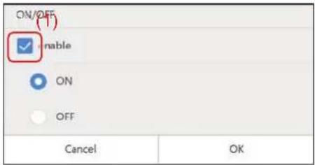 | |
| Operation mode setting [Mode] | To enable the setting, set the check box of [(2)] to and select a value. |
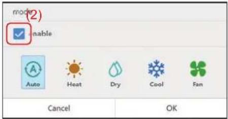 | |
| Set temperature setting [Set temp.] | To enable the setting, set the check box of [(3)] to , tap , then change the set temperature. |
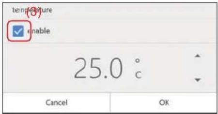 | |
Return Back settings [Return Back]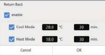 | An energy saving function whereby if you temporarily change the set temperature to one which increases the load, you can automatically return to the energy saving set temperature after a certain time has elapsed. For example, if you set COOL to 82°F/30 minutes, then if the set temperature is set to below 82°F, the Unit will return to 82°F 30 minutes after the change.NOTEDisplayed in the case of a compatible air conditioner. |
Local operation prohibition setting [Lock setting of remote control]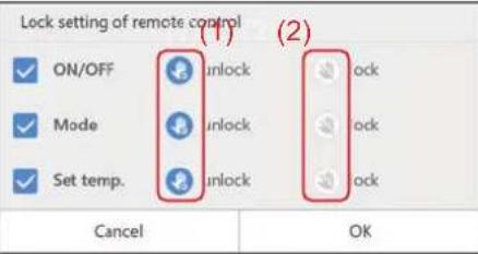 | Tap the check box of the function whose setting you want to change to set it to ,then select [(1)] or [(2)]. |
Save operation setting [Energy saving ratio[%]]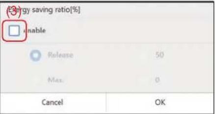 | To enable the setting, set the check box of [(3)] to .For details, see "Control air conditioner power (Energy saving ratio [%])" (Owner's Manual P.46). |
Ventilation operation setting [Ventilation -> ON/OFF]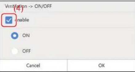 | You can turn ON/OFF the operation of the ventilator connected to the air to air heat exchanger(s) or air conditioner(s). To enable the setting, set the check box of [(4)] to and apply the setting. |
Vent. Mode [Ventilation -> Mode]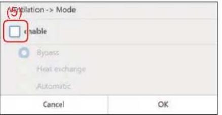 | You can set the ventilation mode of the ventilator connected to the air to air heat exchanger(s) or the air conditioner(s).To enable the setting, set the check box of [(5)] to and apply the setting. For details, see "Set Ventilation Mode (Ventilation → Mode)" (Owner's Manual P.44). |
Delete the operation schedule
You can delete the schedule from either the group screen or the individual control screen. In the following procedure, the individual control screen is used.
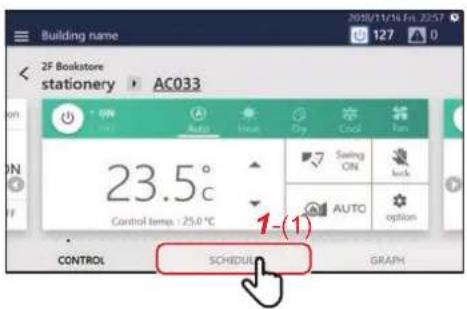
1 Tap [1-(1)] on the group screen or individual control screen
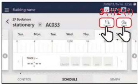
2 Tap [2-(1)] to go to step 4
3 (In case of Particular Timer setting) tap [3-(1)]
Tap > of the schedule you want to modify to go to step 4.
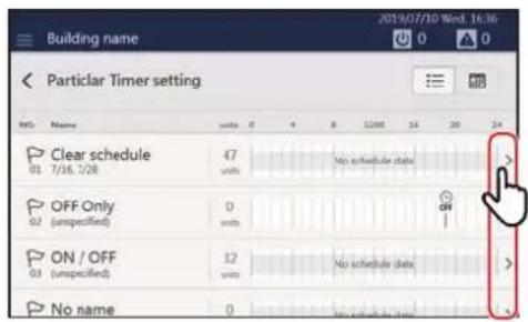
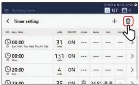
4Tap

(Some displayed items differ between the Week Schedule screen and the Particular Timer setting screen, but the procedure shown below is the same.)
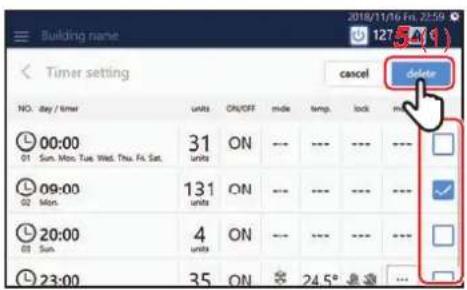
5 Set the check box of the schedule you want to delete to then tap [5-(1)]

1-4. External I/O
Number of points
The external input has the following number of input points.
| Equipment Input/Output Number of points | |
| Main unit | External input 8 points |
| External output 4 points | |
| DIO I/F 1 | External input 8 points |
| External output 4 points | |
| DIO I/F 2 | External input 8 points |
| External output 4 points | |
| DIO I/F 3 | External input 8 points |
| External output 4 points | |
| DIO I/F 4 | External input 8 points |
| External output 4 points | |
* It is necessary to implement crossover wiring with RS-485 for DIO I/F and the main unit.
Functions
The following functions can be set for the main unit and DIO I/F 1 to 4, respectively.
| Input/Output I / O Function Functions Settings | ||||
| Input | Electric power | Count the power pulses.Measure a pulse waveform of 50 msec or more as one pulse. | • Pulse constant (kWh/pulse) | |
| Control | Stop | When ON, stops the specified air conditioner. | • a contact (ON at signal input, OFF at release)/b contact (OFF at signal input, ON at release) | |
| Run | When ON, runs the specified air conditioner. | • a contact (ON at signal input, OFF at release)/b contact (OFF at signal input, ON at release) | ||
| Lock | When ON, controls the specified air conditioner to the specified setting contents. | • a contact (ON at signal input, OFF at release)/b contact (OFF at signal input, ON at release)• Pattern 0 (Stop at ON, do nothing at OFF)/Pattern 1 (Stop at ON, "Run/Stop" at OFF switch prohibit release)/Pattern 2 (Stop at ON + "Run/Stop" switching prohibited, "Run/Stop" at OFF switching prohibited release)/Pattern 3 (Stop/Run) | ||
| Fire alarm | At ON, turn OFF the specified air conditioner and set the local remote prohibited status, and at OFF, release the local remote control prohibited status. | • a contact (ON at signal input, OFF at release)/b contact (OFF at signal input, ON at release) | ||
| Demand | At ON, perform demand control on the specified air conditioner. | • a contact (ON at signal input, OFF at release)/b contact (OFF at signal input, ON at release)• Indoor unit (Thermo OFF (no delay release)/Thermo OFF (10 seconds delay)/Thermo OFF (20 seconds delay)/Thermo OFF (30 seconds delay)/Thermo OFF (60 seconds delay)/FAN/Stop + local remote control operation prohibited/FAN + local remote control mode change prohibited)• Outdoor unit (0%/60%/70%/80%) | ||
| Operation monitoring of external equipment | At ON, displays the associated external equipment as Operation status, and at OFF, displays it as Stop status. | • a contact (ON at signal input, OFF at release)/b contact (OFF at signal input, ON at release) | ||
| Input/Output | I / O Function | Functions | Settings | |
| Input Control | Alarm monitoring of external equipment | At ON, displays the associated external equipment as Alarm detected status, and at OFF, displays it as No alarm. | · a contact (ON at signal input, OFF at release)/b contact (OFF at signal input, ON at release) | |
| Output Control | Air conditioner alarm output | One or more specified air conditioners turn ON when an alarm occurs and turn OFF when the alarm goes OFF. | · a contact (at ON, signal output, at OFF, output Stop) fixed | |
| Operation output | One or more specified air conditioners turn ON when operating, and turn OFF when all turn OFF. | · a contact (at ON, signal output, at OFF, output Stop) fixed | ||
| System alarm output | With this system excluding air conditioners, it turns ON when an alarm occurs and turns OFF when the alarm goes OFF. | · a contact (at ON, signal output, at OFF, output Stop) fixed | ||
| Refrigerant leakage output *During normal operation, do not set. | Turns ON when a refrigerant leakage signal is detected and turns OFF when the detection stops. | · a contact (at ON, signal output, at OFF, output Stop) fixed* During normal operation, do not set. | ||
| Operation output to external equipment | Turns ON when the associated external equipment is operated and turns OFF when stopped. | · a contact (at ON, signal output, at OFF, output Stop) fixed | ||
* Each function can be set in [Server/Interface] - [Interface Settings] in the setting file creation software.
1-5. Power distribution system
"Report Creation Software" is software that creates monthly reports based on the operation results of individual air conditioning units within the air conditioning control system. The software also includes electrical power distribution and charge calculation functions.
The electrical power distribution function distributes the amount of electricity used for each air conditioner, based on the power meter pulse-integrated value measured in the air conditioning control system.
The charge calculation function calculates the charge for each air conditioning unit based on the electric unit price and the amount of electricity distributed to each air conditioner.
Files can be saved in Excel ^® , CSV and PDF formats.

CAUTION
- Using the accumulated power meter with pulse output, the system calculates the distribution of power accumulated by pulse conversion according to the load proportion estimated for each air-conditioner. The result is not calculated based on the Measurement Act and cannot be used officially.
- Even if the operation hour is the same, the amount of power consumed varies depending on operating conditions such as the location of the air-conditioner, the set temperature, and the outdoor temperature.
- The air-conditioner stays on for protection, even while stopped, and power is consumed. Therefore the system also calculates power consumed while the air-conditioner is not in use.
- The system calculates the distribution of power according to the load proportion estimated for each air-conditioner. Therefore the result may differ from the actual amount of power consumed.
- If a single power meter is installed in multiple air-conditioners, the total power is distributed. The result may differ when a power meter is installed in each air-conditioner.
- The system calculates the pulse output using the accumulated power meter with pulse output. The result may differ from the actual amount of power consumed depending on the precision of the power meter. In particular, when the amount of electricity consumed in operation is low (when stopped, etc.), the result may differ from the actual amount of power consumed.
- Please note that we bear no responsibility for any damage or problems that occur due to the system's distribution calculation, data loss, etc.
- The calculation result contains rounding errors.
- The system only supports the distribution calculation of power consumed by the air-conditioner. Please note the above when you use it.
1-6. Data Analyzer
Function outline
This software displays a history graph of operating power consumption or time of air conditioners managed with Air Conditioning Control System. Comparison with previous data of the same conditioner, operating data of another air conditioner, floor, tenant, or other group units allows you to visually check the operating efficiency of the air conditioner.
In addition, when the use of the air conditioner is improved, e.g. when the energy saving priority operation (saving / demand control) is performed on the Air Conditioning Control System or when the set temperature is changed depending on the status, the software displays the energy saving efficiency in graph, which allows you to visually compare and check.
Table 1-1 Function outline
| Function Description Note | ||
| Trend graph display | Displays a graph of operating power consumption or time of air conditioners managed with Air Conditioning Control System. | A graph can be displayed in day (in units of one hour), week (in units of one day), month (in units of one day), and year (in units of one month).In addition, a no-comparison graph can include outdoor temperature, indoor temperature, and set temperature. |
| Performance status display of saving operation / demand control | Displays a graph of the performance status of saving / demand for each unit. | Displayed for each indoor unit. (The demand control display targets an outdoor unit connected to an indoor unit displayed in graph.)The saving operation / demand control can only be displayed when a no-comparison trend graph for indoor unit single selection is set in units of one day. |
| Comparison with previous operating performance data in graph | Displays a graph of operating data of air conditioners managed with Air Conditioning Control System in units of air-conditioner or group. In addition, the reduction rate of power consumption for each hour can be displayed in % and in graph. | Comparison can be performed in units of unit or group such as floor and tenant. A graph can be displayed in day (in units of one hour), week (in units of one day), month (in units of one day), and year (in units of one month). |
| Ranking table of air-conditioners | Displays operating data of air conditioners managed with Air Conditioning Control System in a ranking list.Can be compared in units of air-conditioner or group. | The power consumption and operating time can be compared. |
| Alarm history display | Displays the alarm history in the specified period. | |
| Graph / Data export Exports the displayed graph. | Screen printing using the PC-connected printerJPEG exportGraph screen copy to the clipboardData export for spreadsheet software Can be performed. | |
1-7. Remote monitoring
Settings for Remote Monitoring with a PC
You can monitor and control the Unit by accessing it from a PC. This section explains the settings for the Unit and the PC. Please see "9. Remote monitoring using a PC" (Owner's Manual P.74) for the system diagram and the PC operating environment.
NOTE
Some functions cannot be used from a PC. For details, please see "List by Lock Level/Level" (Owner's Manual P.84)
System diagram

flowchart
graph LR
    A["Computer"] -->|LAN| B["Server with 128 indoor units"]
    B --> C["Desktop with 128 indoor units"]
    C --> D["User with one LAN line to connect up to 128 indoor units"]
Unit settings
1 Set the user account for remote operation (Owner's Manual P.66)
2 Set the IP address (Owner's Manual P.69)
3Set a destination to send email to when an alarm occurs (Owner's Manual P.70)
PC settings
Settings
| IP address/Subnet mask | Set it to be the same network as the Unit.(For details, see the “Network Configuration Guide”.) (Example: the Unit 192.168.2.80/PC 192.168.2.90/subnet 255.255.255.0) |
| Port Release port number 8801. | |
| Drive C | Ensure that you have 500 MB or more free space and start up as a user with read/write authority. |
Operating Environment
The following environment is necessary to use this function.
| OS Windows 8.1, Windows | 10 |
| .NET Framework 4.6.2 | |
| Web browser | Microsoft Edge, Internet Explorer 11, Google Chrome latest version |
Install the software
1 Open the web browser of your PC
2 Access "http://[server name or IP address]/touchscreencontroller/[language code]/download.html"
Server name or IP address
: For the IP address, enter the value set in step 2 of "Unit settings" (P.32).
Language code : Enter the following value according to the language.
| Language Language Code | |
| Japanese | JA |
| English | EN |
| French | FR |
| German | DE |
| Italian | IT |
| Spanish | ES |
| Portuguese | PT |
| Turkish | TR |
| Polish | PL |
| Chinese | ZH |
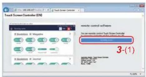
3 Click [3-(1)]
4 Save the file according to the browser message
5Double-click on the saved "installer\_touchscreencontroller.exe" to unzip/install (setup.exe)
When the installation is completed, a shortcut icon is created on the desktop.
NOTE
If .NET Framework 4.6.2 is not installed on the PC, this software will not work properly. Be sure to download and install .NET Framework 4.6.2 from the above website.
Remote monitoring using a PC
You can monitor and control the Unit by accessing it from a PC. This section explains the system diagram and the operating environment. For settings, etc., see "Settings for Remote Monitoring with a PC" (P.32).
NOTE
Some functions cannot be used from a PC. For details, please see "List by Lock Level/Level" (Owner's Manual P.84).
Log in to Remote Control Software
NOTE
Up to 16 users can log in at the same time.
1 Double-click "AMTC_UI_****" on the desktop
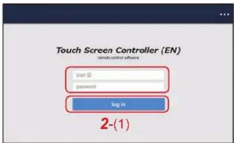
2 Enter [User ID] [password], then click [2-(1)]
User ID/password:
Use the user account set up in step 1 of "Unit settings" (P.32).
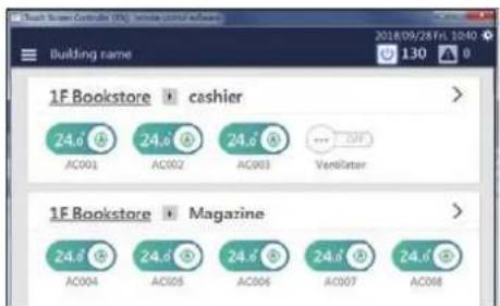
The Remote Control Software home screen is displayed.
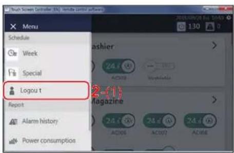
Log out from Remote Control Software
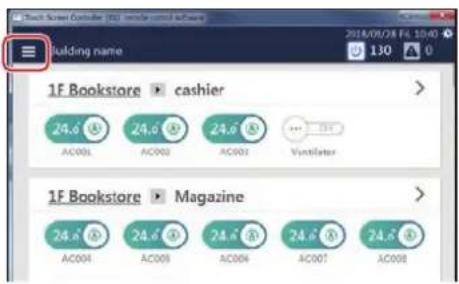
1Click

2 Click [2-(1)]
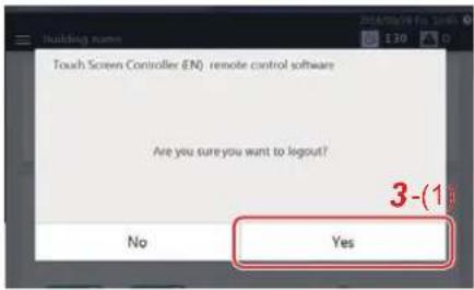
3 Click [3-(1)] You are logged out from the Remote Control Software.
Exit Remote Control Software
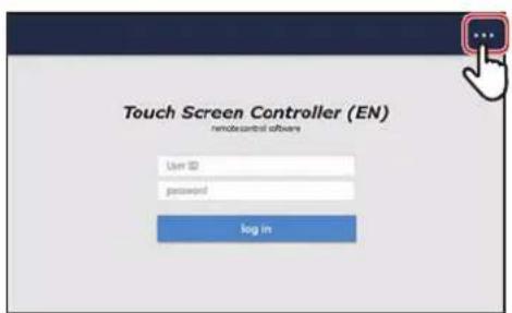
1Tap

2 Tap [2-(1)]
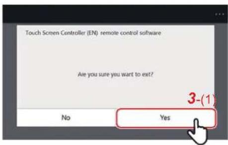
3 Tap [3-(1)] Exit the Remote Control Software.
2System Configuration
2-1. System configuration diagram
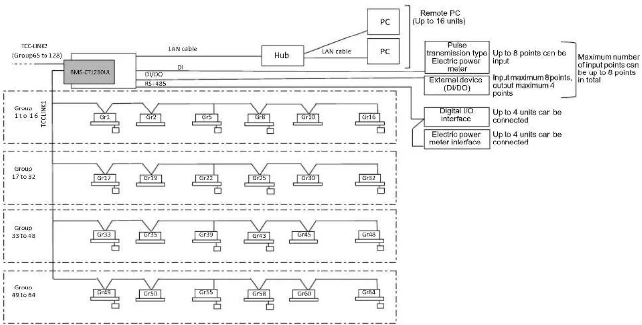
flowchart
graph TD
    A["TCC-LINK2 (Group65 to 128)"] --> B["BMS-CT1280UL"]
    B --> C["LAN cable DI"]
    C --> D["Hub"]
    D --> E["PC"]
    D --> F["PC"]
    E --> G["Remote PC (Up to 16 units)"]
    F --> H["Pulse transmission type Electric power meter"]
    H --> I["External device (DI/DO)"]
    I --> J["Group 1 to 16 TCCLINK1"]
    J --> K["Gr1"]
    J --> L["Gr2"]
    J --> M["Gr5"]
    J --> N["Gr8"]
    J --> O["Gr10"]
    J --> P["Gr16"]
    K --> Q["Group 17 to 32"]
    L --> R["Group 17 to 32"]
    M --> S["Group 17 to 32"]
    N --> T["Group 17 to 32"]
    O --> U["Group 17 to 32"]
    P --> V["Group 17 to 32"]
    W["Digital I/O interface"] --> X["Up to 4 units can be connected"]
    Y["Electric power meter interface"] --> Z["Up to 4 units can be connected"]
    AA["Group 33 to 48"] --> AB["Gr33"]
    AA --> AC["Gr35"]
    AA --> AD["Gr39"]
    AA --> AE["Gr43"]
    AA --> AF["Gr45"]
    AA --> AG["Gr48"]
    AH["Group 49 to 64"] --> AI["Gr49"]
    AH --> AJ["Gr50"]
    AH --> AK["Gr55"]
    AH --> AL["Gr58"]
    AH --> AM["Gr60"]
    AH --> AN["Gr64"]
    style A fill:#f9f,stroke:#333
    style B fill:#ccf,stroke:#333
    style C fill:#cfc,stroke:#333
    style D fill:#fcc,stroke:#333
    style E fill:#cff,stroke:#333
    style F fill:#ffc,stroke:#333
    style G fill:#fcf,stroke:#333
    style H fill:#cff,stroke:#333
    style I fill:#ffc,stroke:#333
    style J fill:#cfc,stroke:#333
    style K fill:#cfc,stroke:#333
    style L fill:#cfc,stroke:#333
    style M fill:#cfc,stroke:#333
    style N fill:#cfc,stroke:#333
    style O fill:#cfc,stroke:#333
    style P fill:#cfc,stroke:#333
    style Q fill:#cfc,stroke:#333
    style R fill:#cfc,stroke:#333
    style S fill:#cfc,stroke:#333
    style T fill:#cfc,stroke:#333
    style U fill:#cfc,stroke:#333
    style V fill:#cfc,stroke:#333
    style W fill:#cfc,stroke:#333
    style X fill:#cfc,stroke:#333
Group=Gr
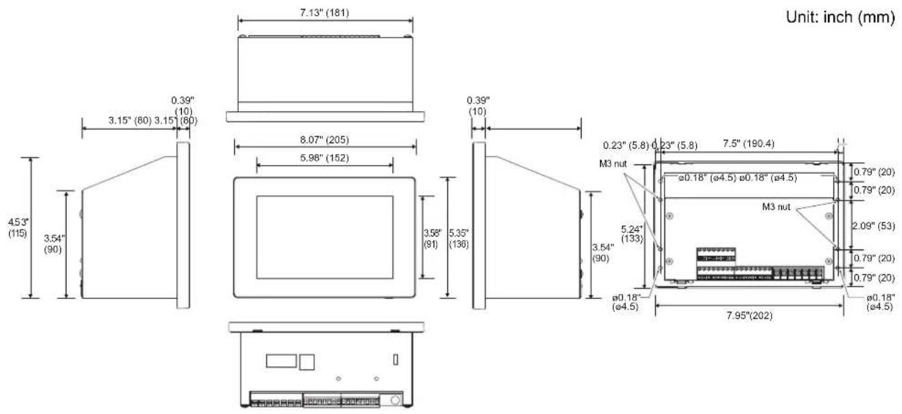
2-2. Outline drawing
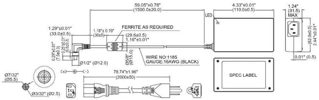
■ Outline drawing
Air Conditioning Control System
Power adapter
3 Initial Settings
3-1. Create local information
When using the template function of the setting file creation software
(1) Start the setting file creation software, select [Tool] - [Output Template] - [Touch Screen Controller(CT128series)], and output the template file.
(2) Fill in each item of "Building Name" "IP Address" "Air Conditioner Information" and "Digital I/O Relay Interface" in the template file.
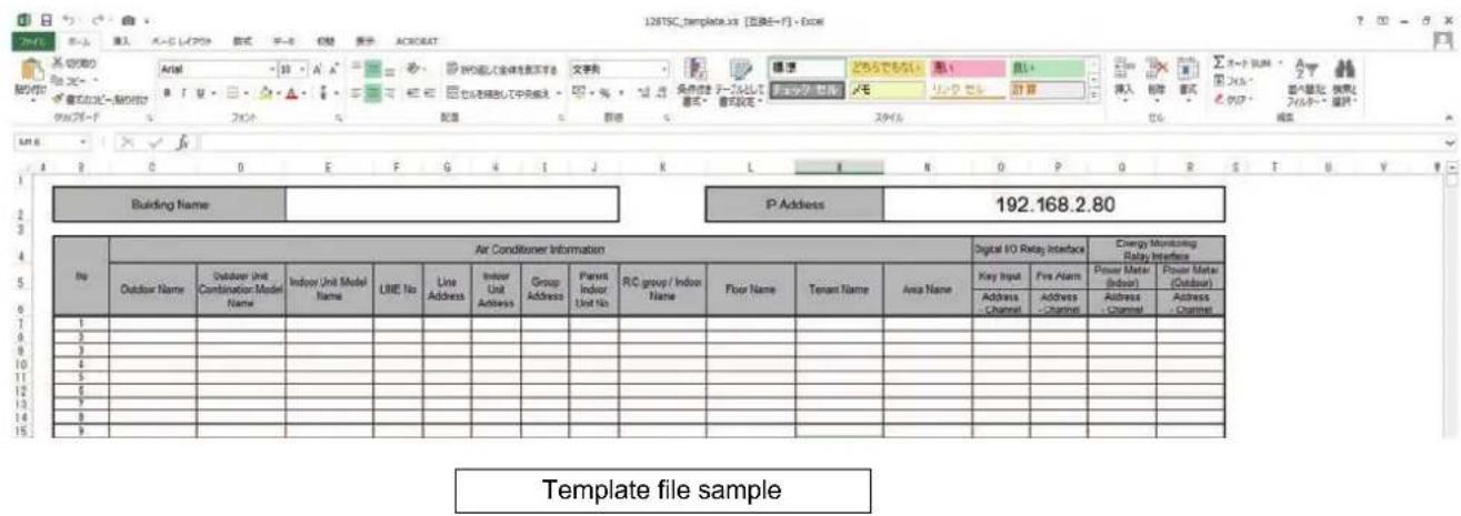
When not using the template function of the setting file creation software
(1) Fill in each item of "Building Name" "IP Address" "Air Conditioner Information" and "Digital I/O Relay Interface" in Excel, etc.
* For details of each item, please refer to the input items of the above template file sample.
3-2. Create setting data with the setting file creation software
When using the template function of the setting file creation software
(1) Start the setting file creation software. Select [Tool] - [Import] - [Touch Screen Controller(CT128series)], and import the template file data.
When not using the template function of the setting file creation software
(1) Start the setting file creation software. Select [New] - [Touch Screen Controller(CT128series)], Input each item entered in the work of "" into the setting file creation software settings screen.
*When using centralized controllers in combination (up to 8 units)
When using centralized controllers in combination including the Unit within the same TCC-LINK, apply the following settings.
When using multiple units of the Unit in combination (master/slave setting)
- The Unit - header unit (1 unit): No setting required
- The Unit - follower unit: Set to follower unit setting using the setting file creation software.
When using in combination with the TouchScreenController (BMS-CT512*)
- TouchScreenController (BMS-CT512*): No setting required
- The Unit: Set to follower unit setting using the setting file creation software.
Also, turn ON 1 of DS25 on the Communication settings screen of the main unit.
When using in combination with SmartBMS manager with data analyzer and a SmartBMS manager
- SmartBMS manager with data analyzer: No setting required
- The Unit: Set to follower unit setting using the setting file creation software.
3-3. Upload setting data
* If LAN connection is difficult after the installation work, please implement "3-3.Upload setting data" before "3-8.Installation work". If LAN connection is easy after installation work, "3-8.Installation work" may be implemented after "3-3.Upload setting data".
(1) Confirm that the setting content matches the on-site system.
(2) Connect the PC with the setting file creation software and the TouchScreenController main unit with a LAN cable.
(3) Confirm that the HOME screen displays after turning on the main unit (after about 4 minutes).
(4) Set the PC's IP address to the same network as the TouchScreenController such as 192.168.2.80.
(5) Display "Upload setting" in [File] - [Upload] in the setting file creation software.
(6) Confirm that it is connected to the TouchScreenController with the [ping] button.
(7) Upload the setting file to the TouchScreenController with the "Upload" button.
3-4. Setting up by the controller only
With this controller (software version 10.1.7.0 and later), air-conditioning units can be registered and area names and other settings below can be configured without using the setting file creation software that is required for conventional setup. A conventional setup using the setting file creation software is necessary when other settings are required.
Setting items that can be configured by the controller (without using the setting file creation software)
| No. Setting Item Setting Menu | ||
| 1 | Indoor unit registration [Menu]-[Service settings]-[Central management address Setting] | |
| 2 | Indoor unit area setting [Menu]-[Indoor unit area setting] | |
| 3 | Indoor unit name setting (single-byte alphanumeric characters only) | [Menu]-[Indoor unit name setting] |
| 4 | Area name setting(single-byte alphanumeric characters only) | [Menu]-[Area name setting] |
3-5. Starting/exiting the service settings
[Service settings] is usually hidden. The following procedure can be used to display the [Service settings] and start the service menu.
[Service settings] enables manipulation of the following three items.
| Item Function | |
| Cancel service mode The service menu is exited, and the [Service settings] are hidden. | |
| Communication Communication settings can be configured. | |
| Central management address Setting | The central management addresses and communication settings of the setting file of indoor units can be changed. |
Starting the service settings
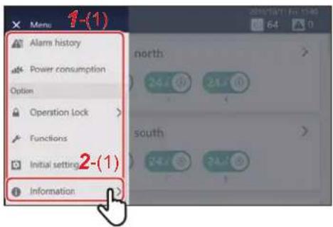
1Tap
[1-(1)] appears.
2 Scroll through the menu list and tap [2-(1)]
The Information screen appears.
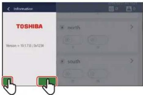
3Tap and hold the lower left and lower right of the Information screen at the same time for about five seconds
After the sections that were tapped and held turn green, tap to return to the menu.
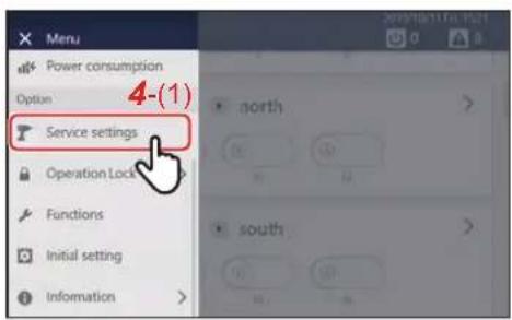
4Tap [4-(1)]
The [Service settings] are displayed, and the service menu starts.
Exiting the service settings
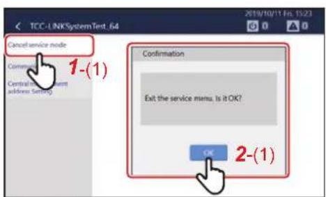
1Tap [1-(1)]
2Tap [2-(1)]
The service menu is exited, and the [Service settings] are hidden.
3-6. Communication settings
The communication settings of TCC-LINK (DS25) can be changed. To change the settings, start the service settings using "3-5.Starting/exiting the service settings" (P.40).
Changing the communication settings
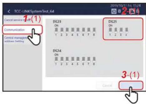
1 Tap [1-(1)] of the [Service settings] items
2 In [2-(1)], change the communication settings Tap items to toggle between ON (top side) and OFF (bottom side).
3Tap [3-(1)] The changed content is confirmed.
| No. 1 No. 3 | Used together with central controller*1 | Connection of device"without remote controller"*2 | Release or no release of the local remote control operation prohibition setting during recovery of an indoor unit power outage | ||
| 512-Line Touch Screen Controller | Non-512-Line Touch Screen Controller | ||||
| OFF OFF | Not possible P | Possible Not possible Re | leased | ||
| OFF | ON | Setting prohibited (L20 (Central management address overlap) may be detected)) | |||
| ON OFF | Possible Not possible Not possible Released | ||||
| ON ON | Possible Not possible Possible Not released | ||||
NOTE
*1 When a Non-512-Line Touch Screen Controller is used at the same time, follow the settings of [Used together with central controller] → [Non-512-Line Touch Screen Controller].
*2 When a local remote controller is not connected to the indoor unit, a "without remote controller" icon is displayed to the right of the indoor unit name.
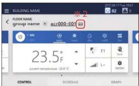
Confirmation of power pulse
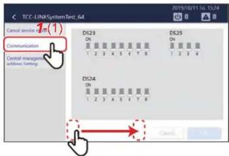
1 Tap [1-(1)] of the [Service settings] items
2At the communication settings screen, swipe the empty space at the bottom from left to right
The confirmation screen for power pulse signals appears.
Power pulse signal confirmation screen
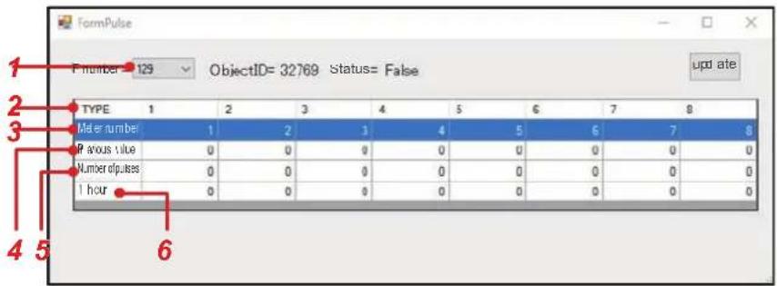
| No. Function | |
| 1 | The watt hour meter to be displayed in the pulse table can be selected.In the case of the main unit and the watt hour meter IF, this is [128] and [128 + address number], respectively. The item can be switched by tapping the pulldown menu. |
| 2 Shows the channel number. | |
| 3 Shows the pulse number configured by the setting file creation software. | |
| 4 | Shows the input value of the pulse.The input count of the pulse can be checked by this section. |
| 5 Shows the total value (for one day) for a daily report. | |
| 6 Shows the one-hour total value for the trend. | |
NOTE
The pulse table is updated in 30-second cycles because the power pulse signal is acquired by internal communication.
3-7. Central management address Setting
Using the [Central management address Setting], the central management addresses and setting file of the indoor units can be configured and changed.
To change the settings, start the service settings using "3-5.Starting/exiting the service settings" (P.40).
NOTE
If you leave the Central management address Setting screen, a restart is required.
Setting and changing central management addresses
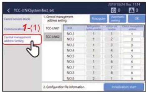
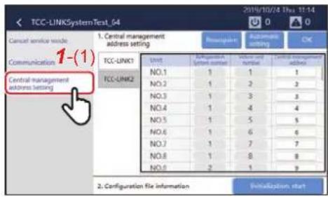
1 Tap [1-(1)] of the [Service settings] items
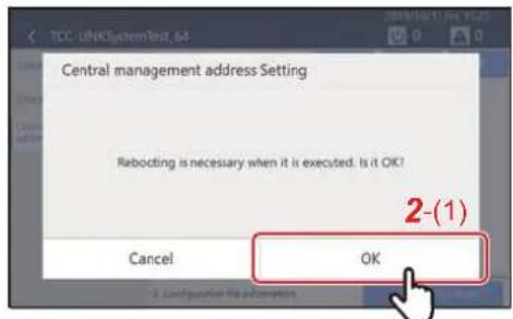
The following message appears: [Rebooting is necessary when it is executed. Is it OK?]
2Tap [2-(1)]
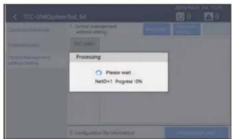
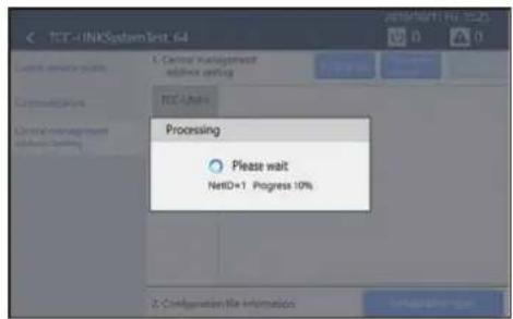
Connection information is acquired. (This takes about five minutes.)
If the connection information is acquired, the Central management address Setting screen appears.
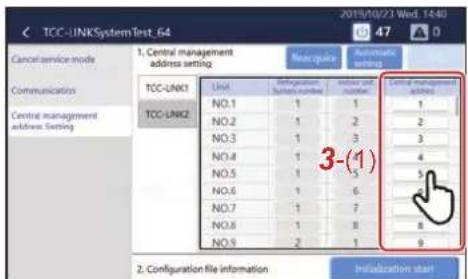
3 Using [3-(1)], tap a Central management address to be configured or changed
The Central management address selection screen appears.
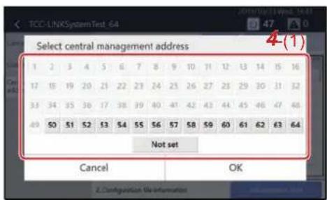
4 Using [4-(1)], tap the Central management address to be configured or changed
NOTE
A blue vertical line appears to the left of the selected Central management address.
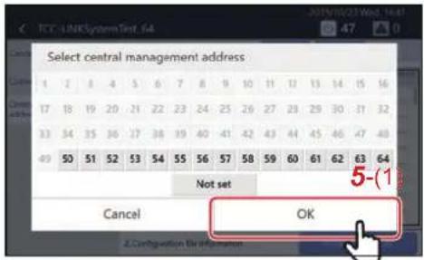
5Tap [5-(1)]
The Central management address of the selected indoor unit is configured.
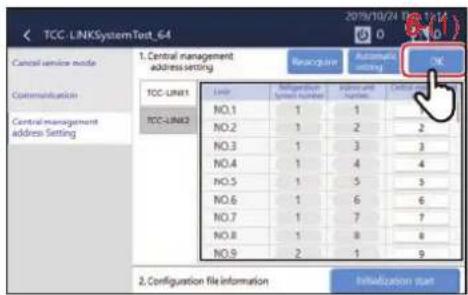
6Tap [6-(1)]
The configured content is confirmed.
Automatic assignment
Central management addresses can be assigned automatically to all indoor units. Following section explains the automatic assignment procedure.
1 Tap [1-(1)] of the [Service settings] items
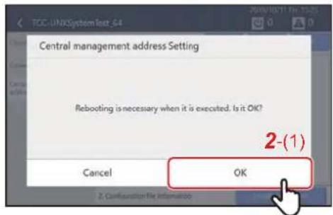
The following message appears: [Rebooting is necessary when it is executed. Is it OK?]
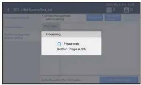
2Tap [2-(1)]
Connection information is acquired. (This takes about five minutes.) If the connection information is acquired, the Central management address Setting screen appears.
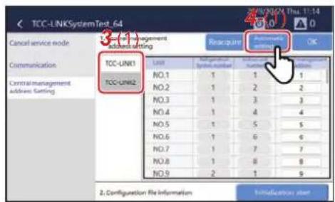
3Select Central management addresses to be automatically assigned from [3-(1)]
If this is tapped, the following message appears: [Automatic assignment of TCC-LINK1 (or TCC-LINK2) will be performed. Continue?]
4Tap [4-(1)]
Automatic assignment of the Central management address is performed for the selected TCC-LINK. (This takes about three minutes.)
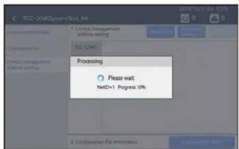
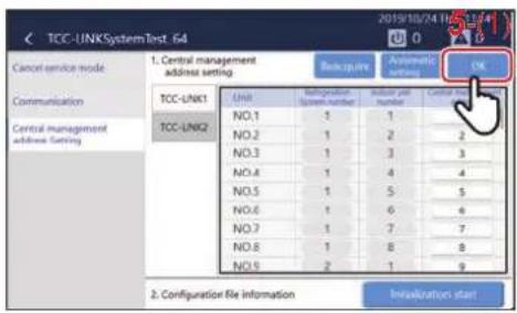
5Tap [5-(1)]
The configured content is confirmed.
Reacquisition
The connection information of the indoor units can be re-acquired. Following section explains the reacquisition procedure.
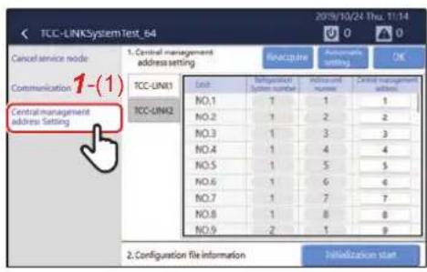
1 Tap [1-(1)] of the [Service settings] items
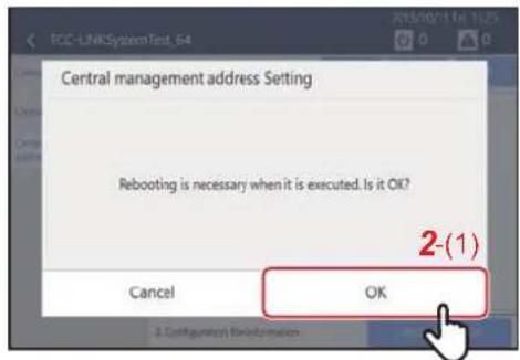
The following message appears: [Rebooting is necessary when it is executed. Is it OK?]
2Tap [2-(1)]
Connection information is acquired. (This takes about five minutes.)
If the connection information is acquired, the Central management address Setting screen appears.
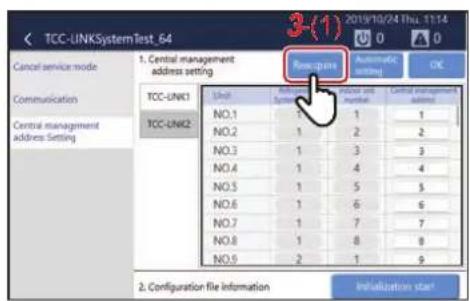
3Tap [3-(1)]
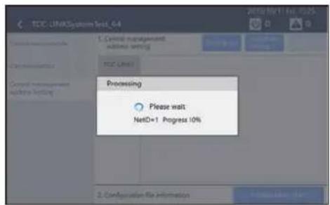
Connection information is re-acquired. (This takes about five minutes.)
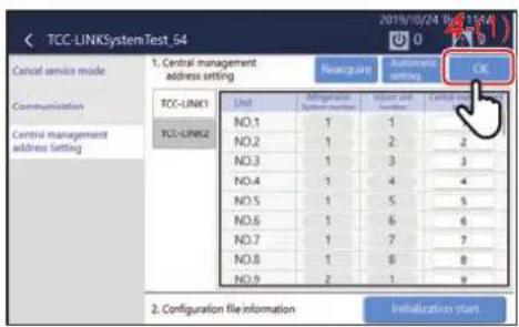
4Tap [4-(1)]
The configured content is confirmed.
Setting file information
A setting file can be created based on acquired indoor unit connection information.
Indoor units can be registered without using the setting file creation software during installation of this controller, expansion of indoor units, or relocation of equipment.
Following section explains the procedure to create or change the setting file.
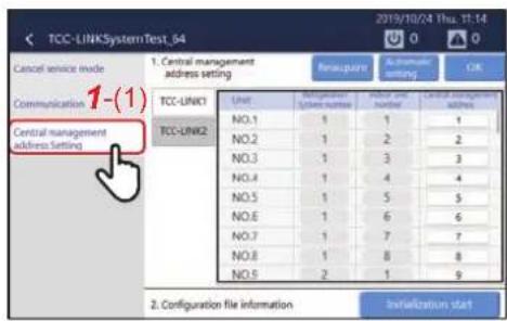
1 Tap [1-(1)] of the [Service settings] items
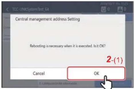
The following message appears: [Rebooting is necessary when it is executed. Is it OK?]
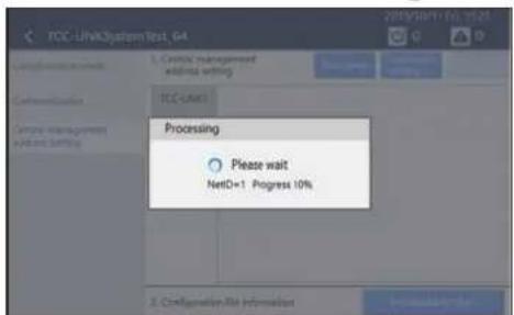
2Tap [2-(1)]
Connection information is acquired. (This takes about five minutes.)
If the connection information is acquired, the Central management address Setting screen appears.
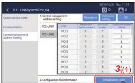
3Tap [3-(1)]
The Automatic registration of indoor unit pop-up appears.
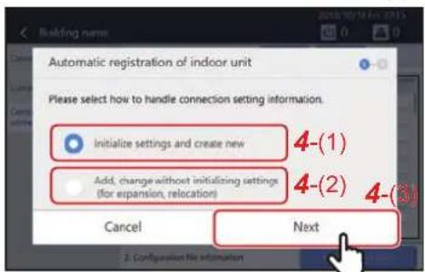
4 Select [4-(1)] or [4-(2)], and then tap [4-(3)]
Select [4-(1)] for [Initialize settings and create new] or select [4-(2)] for [Add, change without initializing settings (for expansion, relocation)].
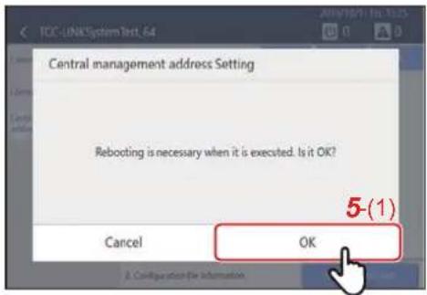
The following message appears: [Rebooting is necessary when it is executed. Is it OK?]
5Tap [5-(1)]
Automatic registration configuration is started. (This takes about five minutes.)
| Item Content | |
| Initialize settings and create new | · Initialize settings and create a setting file based on connection information.· All items such as indoor unit names and area information are deleted. |
| Add, change without initializing settings (for expansion, relocation) | · Change the setting file based on connection information without initializing the setting file.· The names for newly added indoor units are configured automatically.· Items such as indoor unit names and area information are retained.· Items that are not included in the newly acquired information are deleted from the setting file. |
3-8. Installation work
Installs the main unit. For the installation method, refer to the installation manual that came with the product.
3-9. Trial operation
(1) Confirm that the settings are reflected on the TouchScreenController(CT128) screen normally by switching ON/OFF, changing the set temperature, and changing the Mode from the remote control of each air conditioner.
(2) From the TouchScreenController(CT128) screen, switch ON/OFF, change the set temperature, and change the Mode and confirm that the air conditioners operate normally.
4Troubleshooting
| Phenomenon Question Confirmation items | ||
| The LCD does not display. | Is the power turned on? | Check that the power is not turned off by the breaker or the like. There is a green LED at the lower rear of the main unit and a green LED on the AC adapter that indicate that power is being supplied. |
| Check that the wiring of the power outlet and AC adapter is not disconnected.There is a green LED at the lower rear of the main unit and a green LED on the AC adapter that indicate that power is being supplied. | ||
| Has the backlight gone out? | The LCD turns off when there is no operation for a certain period of time. Touch the touch panel to turn on. The brightness and display time can be changed using [Backlight]. | |
| Is the backlight brightness dark? Adjust the brightness using [Backlight]. | ||
| The operated air conditioner does not run. | Does the operated air conditioner match the actual air conditioner? | Operate another air conditioner and check if the actual air conditioner operates. |
| Is an alarm occurring? | The air conditioner will not operate when an alarm is occurring. Turn off the alarm. | |
| Are you operating with the local remote control? | Even if the air conditioner is run with this Unit, if it is stopped afterwards with the local remote control, it will stop. The latter operation of this Unit or the local remote control overrides the former. | |
| Is the air conditioner stopped due to the schedule setting of the local remote control or the like? | Even if the air conditioner is run with this Unit, if it is stopped afterwards with the local remote control schedule, it will stop. The latter operation of this Unit or the local remote control overrides the former. | |
| Are you operating with the PC app "Remote Control Software"? | Even if the air conditioner is run with this Unit, if it is stopped afterwards with the PC app "Remote Control Software", it will stop. The latter operation of this Unit or the "Remote Control Software" overrides the former. | |
| I want to turn off the power. | There is no power switch. | Please remove the AC adapter or turn off the circuit breaker. |
| I want to reboot. | Reboot from the menu. | Select [Menu] - [Functions] - [System reboot]. |
| The air conditioner settings change arbitrarily. | Are you operating with the local remote control? | Even if the air conditioner is run with this Unit, if it is stopped afterwards with the local remote control, it will stop. The latter operation of this Unit or the local remote control overrides the former. |
| Is the air conditioner stopped due to the schedule setting of the local remote control or the like? | Even if the air conditioner is run with this Unit, if it is stopped afterwards with the local remote control schedule,it will stop. The latter operation of this Unit or the local remote control overrides the former. | |
| Have you applied settings such as stop using an external input signal? | When stop, etc. is set by an external input signal using the external interlocking function, the air conditioner stops automatically when a signal is input. | |
| Are you operating with the PC app "Remote Control Software"? | Even if the air conditioner is run with this Unit, if it is stopped afterwards with the PC app "Remote Control Software", it will stop. The latter operation of this Unit or the "Remote Control Software" overrides the former. | |
| The schedule does not work. | Is the schedule disabled? | Please confirm the Scheduler Operation settings. |
| Does the scheduled air conditioner match the actual air conditioner? | Operate another air conditioner and check if the actual air conditioner operates. | |
| Is a Particular Timer setting set? | If a day is set in both the Week Schedule and a Particular Timer setting, the Particular Timer setting will apply for that day. | |
| The air conditioner doesn't cool. The air conditioner doesn't heat. | Is demand control turned on? | Demand control suppresses the capability of the outdoor unit in order to reduce power consumption. Therefore, it may take time to reach the set temperature. |
| Is the forced thermo OFF control turned on? | Forced thermo OFF is a control to stop the operation of the outdoor unit. Therefore, the indoor unit acts as a fan. | |
| Is the power saving control turned on? | Power saving suppresses the capability of the outdoor unit. Therefore, it may take time to reach the set temperature. | |
| The LCD does not turn off. | Is an alarm occurring? | The LCD will still be on when an alarm is occurring. Turn off the alarm. |
| Sometimes the LCD becomes black for a moment. | The LCD's antistatic control is working. | Temporarily stop the LCD periodically to prevent LCD burn-in. Not a malfunction. |
| The setting displayed on the local remote control does not match the setting displayed on this Unit. | Does the operated air conditioner match the actual air conditioner? | Operate another air conditioner and check if the actual air conditioner operates. |
| I would like to frequently change detailed settings such as set temp. and setting mode for all air conditioners. | Only "ON" and "OFF" can operate all air conditioners at once. | You can set the set temp., setting mode, etc. for each air conditioner group by group. Please group the air conditioners. |
| When local remote control operation is prohibited, if there is a power failure, the local remote control prohibited status will be cancelled when the power returns. | Check [Menu] - [Service settings] - [Communication]. | Set [Menu] - [Service settings] - [Communication] as follows. DS25-3... If you want to continue the local remote control prohibited status after returning from a power failure, please turn ON. |
| FILTER information can be reset even when the FILTER sign is not displayed. | The FILTER signs lights up depending on the accumulated operation time. | As the operation time accumulates, the FILTER sign lights up when the preset operation time is reached. The FILTER sign information can be reset to clear the accumulated time for cases such as when FILTER cleaning is carried out before the FILTER sign turns on. |
| I want to check the software version. | Reboot from the menu. The version is | displayed under [Menu] - [Information]. |
| Reboot from time to time. Please check for noise and the power supply status. | The main unit may restart if noise in the surroundings or an unstable power supply cause the operation of the software to be unstable. Please check the surrounding environment. | |
| I cannot start the Remote Control Software. | Is "Error 1001" displayed? | Please download .Net Framework 4.6.2 from the download website of this software and install it. |
| Is the LAN cable connected? | This software will not start unless the PC and the LAN of this Unit are connected. Check the LAN cable connection and network settings. | |
| Is the IP address of the access destination set to the IP address of the controller main unit? | The IP address (or server name) to be entered during installation is the IP address of the controller main unit. It is not the IP address of the PC. If it is incorrect, please do the following and then reinstall. 1. Uninstall the application 2. Delete the install destination directory 3. Delete the desktop and start menu shortcuts | |
| Is the PC on which the software was installed Windows 8.1 or 10? | Windows 8.1 and 10 are supported. The software may not operate correctly when installed on a PC with a different OS. | |
| I cannot log in to the Remote Control Software. | Have you logged in as the same user from another PC? | Each user can log in from only one PC at the same time. |
| Is the Windows display style set to classic style? | Please select a display style other than classic style. You can change the display style from [Start] - [Control Panel] - [Appearance and Personalization] - [Change the theme]. This software supports Windows 8.1 and 10. | |
| I cannot log in to Remote Control Software from another PC after the LAN is disconnected. | Have you logged in with the same user ID? | You must log in again from a PC with the LAN disconnected and log out normally. |
| Have you accessed the software from more than 8 PCs? | Up to 8 PCs can be accessed at the same time. The software may not operate correctly if you connect to more than 9 PCs. | |
| Did you assign the PC's IP address using a DHCP server? | This Unit judges whether it is accessed from the same PC using the IP address.If the PC address is changed partway through by the DHCP server, you may not be able to log in again after LAN disconnection. Please set the PC that accesses this Unit to a fixed IP or reboot the Unit and erase the login information. | |
| The language does not switch with the Remote Control Software. | Does the login user for the Windows being used have write permission for the Remote Control Software storage location? | Please allow write permission below the folder where Remote Control Software is saved (initial setting: C:\Program Files\TOSHIBA Carrier Corporation).Right-click on the TOSHIBA Carrier Corporation folder, select the [Properties] - [Security] Name, click the "Edit" button and check [Allow] for [Full control] under different settings. |
| The schedule setting changes have not been reflected. | Are you trying to change the schedule settings on both the Remote Control Software and the main unit? | To change the schedule settings, please set only one of either the main unit or the Remote Control Software. |
| I would like to use the software with other centralized controllers. | Centralized controllers that can be used together within the same TCC-LINK. | It is possible to use up to 8 units together with all centralized controllers including this Unit.Ask service personnel to use them in combination. |
| I would like to use the software with other centralized controllers. | Centralized controllers that can be used together within the same TCC-LINK. | It is possible to use up to 8 units together with all centralized controllers including this Unit.To use them in combination, please set [Menu] - [Service settings] - [Communication] as follows.DS25-1... Please turn this setting ON when using centralized controllers in combination. |
| I want to use multiple units in combination. | Number of units that can be used in combination in the same TCC-LINK. | It is possible to use up to 8 units together with all centralized controllers including this Unit.To use them in combination, please set [Menu] - [Service settings] - [Communication] as follows.DS25-1... Please turn this setting ON when using centralized controllers in combination. |
| The multi outdoor unit's option board control does not work. | Do you want to use the multi outdoor unit's option board? | When the centralized controller is connected, the functions of the outdoor unit's option board become ineffective. Only one of the centralized controller and the outdoor unit's option board can be used. |
| About communication settings in [Service settings]. | Do you want to use centralized controllers in combination or use the local remote control prohibition settings? | If you change the setting to unnecessary, the Unit may not work properly. If it has been set, please return it to the initial value (only DS25-2 ON).The following settings should be used.DS25-1... To use centralized controllers in combination, turn this setting ON.DS25-3... If you want to continue the local remote control prohibited status after returning from a power failure, please turn this setting ON. |
| The Unit does turn ON/OFF even though the operation interlock signal/stop interlock signal is input. | Has the interlock signal been input from the time of activation? | Since the interlock signal confirms the state by detecting the rising edge and falling edge, if the interlock signal is input from the time of activation, interlock control will not be performed. Please set so that the interlock signal turns OFF at the time of activation. |
5Service Parts
| No. | Component name | Component code | Overview | Q'ty |
| 1 | Power adapter 4316V58 | 1 Power supply adapter for Touch Screen Controller 1 |
Installation Manual
TOSHIBA
Carrier
Air Conditioning Control System (Touch Screen Controller) Installation Manual
Model name:
BMS-CT1280UL
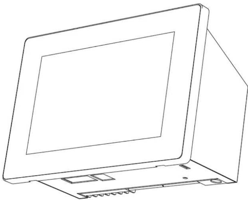
natural_image
Line drawing of a laptop computer with open lid and rear panel (no text or symbols)- Save These Instructions!
- Thank you for purchasing the TOSHIBA air conditioning control system.
- Please read this installation manual carefully before installation, and perform the work only in the correct manner.
Contents
1 Precautions for safety....3
2 Specifications .... 5
3 Installation 8
3-1. Installation of Main Unit Box and Panel 8
3-1-1. When Installing from the Front 8
3-1-2. When Installing from the Rear....9
3-2. Attaching the Power Adapter 10
3-3. Power, Signal, and Earth Line Connections ..... 11
1Precautions for safety
- Read these "Precautions for safety" carefully before installation.
- The precautions described below include important items regarding safety. Observe them without fail.
Understand the following details (indications and symbols) before reading the body text, and follow the instructions.
- After the installation work has been completed, perform a trial operation to check for any problems. Explain how to use and maintain the unit to the customer.
Ask customer to keep this Manual at accessible place for future reference.
| Indication Meaning of Indication | |
 | Text set off in this manner indicates that failure to adhere to the directions in the warning could result in serious bodily harm (*1) or loss of life if the product is handled improperly. |
 | Text set off in this manner indicates that failure to adhere to the directions in the caution could result in serious bodily injury (*2) or damage (*3) to property if the product is handled improperly. |
*1: Serious bodily harm indicates loss of eyesight, injury, burns, electric shock, bone fracture, poisoning, and other injuries which leave aftereffect and require hospitalization or long-term treatment as an outpatient.
*2: Bodily injury indicates injury, burns, electric shock, and other injuries which do not require hospitalization or long-term treatment as an outpatient.
*3: Damage to property indicates damage extending to buildings, household effects, domestic livestock, and pets.
| Symbols Meaning of Symbols | |
| “Indicates prohibited items.The actual contents of the prohibition are indicated by a picture or text placed inside or next to the graphic symbol. | |
| “Indicates compulsory (mandatory) items.The actual contents of the obligation indicated by a picture or text placed inside or next to the graphic symbol. | |
| WARNING | |
| Ask an authorized dealer or qualified installation professional to install or reinstall this unit.Inappropriate installation may result in electric shock or fire.Electrical work must be performed by a qualified electrician in accordance with this installation manual.The work must satisfy all local, national and international regulations.Inappropriate work may result in electric shock or fire.Be sure to turn off all main power supply switches before starting any electrical work.Failure to do so may result in electric shock. | |
| Do not modify the unit.A fire or an electric shock may occur. | |
| Always connect to groundImproper grounding may result in an electric shock.Before connecting the power, carry out Class D grounding according to the “Engineering Standard for Electric Work” and the “Internal Wiring Regulations”. | |

CAUTION

- Do not install in the following locations:
Locations where combustible gas may leak
Locations with high humidity or water
Dusty locations
Locations in direct sunlight and locations subject to high temperatures
Locations within 3.28' (1 m) from televisions or radios
Outdoors, under awnings, or other locations exposed to rain and dew
Locations exposed to outside air containing corrosive gases or salinity
Locations with frequent vibrations
- Do not operate the touch panel with mechanical pencils or other pointed objects.

- In installation work, use wiring with the correct ampacity.
Failure to do so may result in excessive heat or fire.
- Use specified cables and connect them securely, and do not subject connecting terminals to external force.
Doing so may result in broken cables, excessive heat or fire.
• Always install a circuit breaker on the primary side of the power supply.
- Clean the touch panel by wiping with an eyeglasses cleaner or other soft cloth. To remove oil-based ink, wipe with a cloth that has been moistened with a neutral detergent and then wrung out, and finish by wiping with a soft, dry cloth.
Do not use commercial OA cleaners, cleansers, or other liquid cleaners containing abrasives.
- When attaching to a metal lath, wire lath or wooden structure with metal boards, attach it to the control panel, etc. without attaching it to the wall.
CAUTION This device uses a lithium battery. Follow all local regulations when disposing of it.
2Specifications
| Product name Touch Screen Controller | ||
| Model Name BMS-CT1280UL | ||
| Power supply 120 V AC 60 Hz | ||
| Number of connected units | Indoor unit | Up to 128 units(TCC-LINK 1 maximum 64 units, TCC-LINK 2 maximum 64 units) |
| Power meter interface Up to 4 units | ||
| Digital I/O interface Up to 4 units | ||
| Communication ports | • RS-485 port ×1• LAN port ×1 | |
| USB port USB memory stick connection port ×2 | ||
| External contact input 8 inputs | ||
| External contact output 4 outputs | ||
| Operating temperature/humidity range | 32 to 104°F (0°C to 40°C), 10% to 90% RH (no condensation) | |
| Dimensions | H5.35"×W8.07"×D0.39" (H136 mm×W205 mm×D10 mm)(+3.15" (+80 mm))(Embedded dimensions shown in parenthesis) | |
| Mass | 2.95 lb (1.34 kg) (Touch Screen Controller)0.99 lb (0.45 kg) (power adapter) | |
■ Outline drawing
Air Conditioning Control System
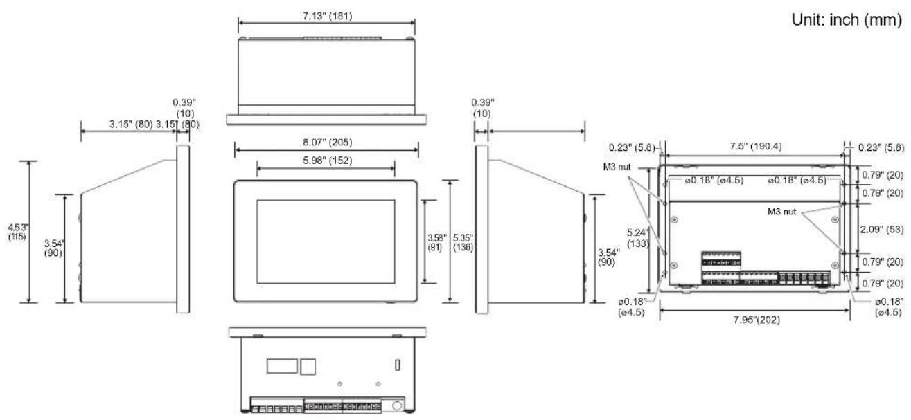
Power adapter
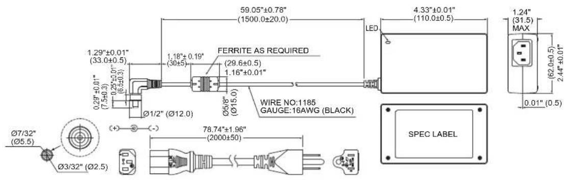
■ Component Names
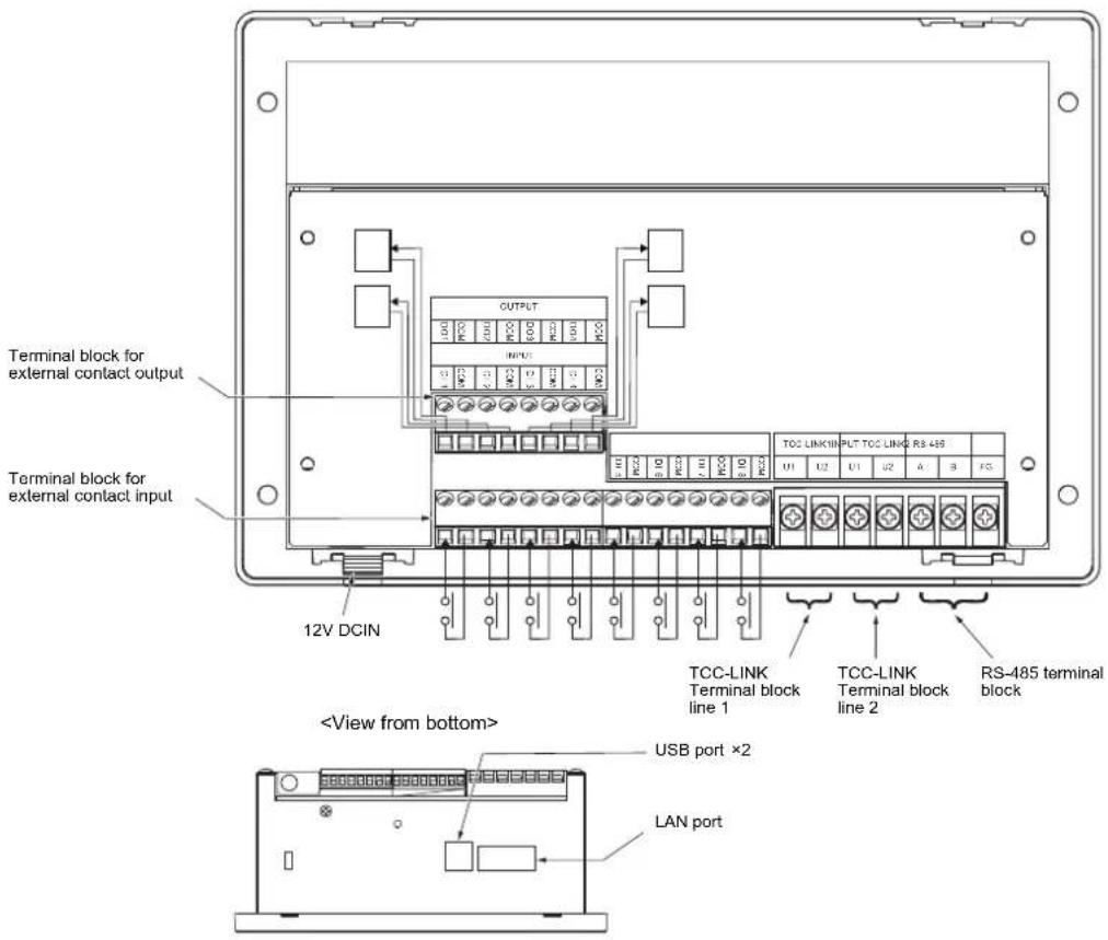
| Name Function | |
| 12V DCIN Connect the power adapter | |
| Terminal block for external contact output | Connect the external contact output |
| Terminal block for external contact input | Connect the external contact input |
| TCC-LINK terminal block | Connect the TCC-LINK 1 and TCC-LINK 2 signal wires |
| RS-485 terminal block Connect the RS-485 | terminal block |
| USB For service | |
| LAN | Can be connected to a PC via LAN communication and monitored and controlled |
■ Before Installation
Confirm that all the parts listed below are included in the package.
Included Items
| No. | Component name Quantity Remarks | |||
| 1 | Main unit 1 | |||
| 2 | Power adapter 1 | |||
| 3 | Power cable 1 | |||
| 4 | Owner's Manual 1 | |||
| 5 | Installation Manual 1 | |||
| 6 | D | V | D - R | 1 |
| 7 | Fixing screw 4 | Fixing screw (M4×0.47" (12 mm)) for attaching the main unit from the front | ||
| 8 | Fixing screw 4 | Fixing screw (M3×0.31" (8 mm)) for attaching the main unit from the rear | ||
| 9 | Closed end connector | 2 | RS-485 cable crimp connector | |
| 10 | Binding band | 2 | For fixing the power adapter | |
| 11 | Double-sided tape | 1 | For fixing the power adapter | |
Wiring specifications
Use the following wiring material to connect signal wires and power supply wires. (Locally procured)
| No. | Wiring | Wire type / wire diameter / wire length |
| 1 For | TCC-LINK | Microphone cord (shielded) (two-core) for instrumentation |
| 1.25 mm^2 , up to 3 281 ft (1 000 m) (total extension distance) 2.00 mm^2 , up to 6 562 ft (2 000 m) (total extension distance) | ||
| 2 For | RS-485 | Microphone cord (shielded) (two-core) for instrumentation |
| 1.25 mm^2 , up to 1 640.5 ft (500 m) (total extension distance) | ||
| 3 For | digital I/O | Two-core cable 0.3 mm^2 , up to 328.1 ft (100 m) |
| 4 For | Ethernet | LAN cable (category 5 or above)Maximum length: 328.1 ft (100 m) |
3Installation
CAUTION
- Do not wire communication lines or input/output wiring next to power supply wiring, etc., or house them in the same metal pipe. Doing so may result in failure.
• Install the main unit away from noise sources.
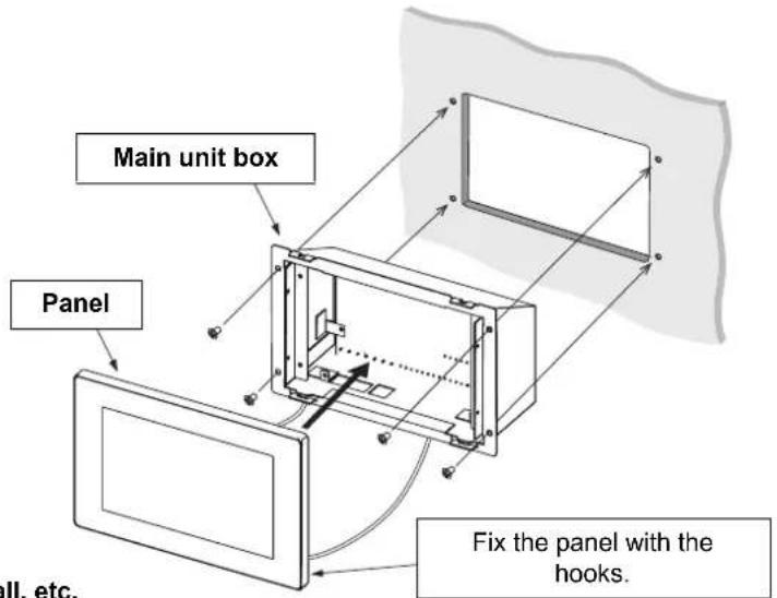
3-1. Installation of Main Unit Box and Panel
The main unit box can be mounted either from the front or from the rear.
3-1-1. When Installing from the Front
Air conditioning control system to wall, etc. fixing hole dimensions
Hole dimensions to drill in wall
Unit: inch (mm)
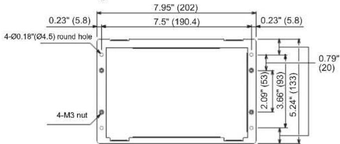
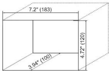
* Since the left and right mounting screws are attached close to each other, please drill the left and right dimensions as accurately as possible.
1 Connect the TCC-LINK cable, AC adapter, and LAN cable to the main unit.
2Fit the main unit on to the wall and switch board.
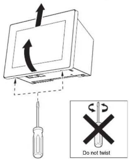
3 Insert a flat head screwdriver, etc. into the groove on the left and right of the bottom of the panel. There will be a snapping sound and the panel will come off.
REQUIREMENT
- Just insert the screwdriver and do not twist it.
• To prevent the panel from falling, support it during removal.
4 Fix the 4 main unit screws.
5 Close the panel by hooking the panel rear to the top of the main unit. There will be a snapping sound and the panel will be fixed.
6 When installation is completed, peel off the transparent film.
3-1-2. When Installing from the Rear
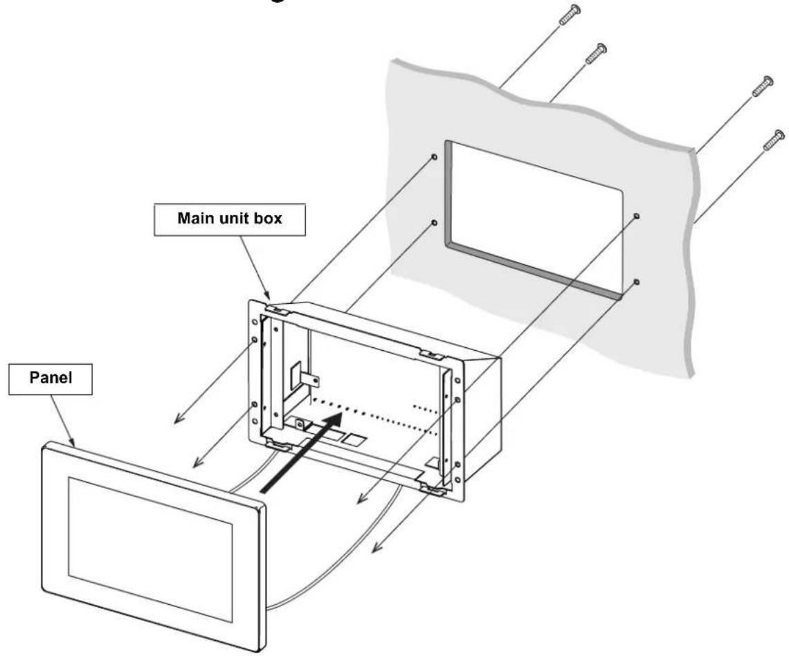
EN
Air conditioning control system to wall, etc. fixing hole dimensions
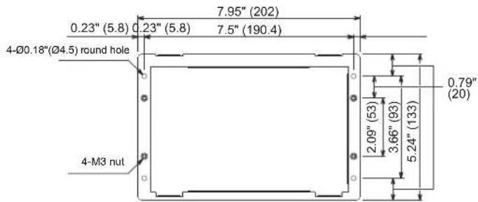
Hole dimensions to drill in wall
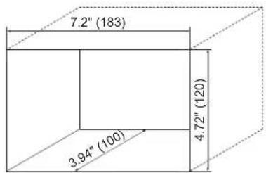
Unit: inch (mm)
* Although the panel and the main unit box are separated to explain the screw attachment part in an easy to understand manner, it is not necessary to remove the main unit box from the panel in actual installation work.
1 Drill four ∅0.16" (4 mm) holes in the switchboard, wall, etc.
2Fit the main unit on the switch board, wall, etc.
3 Fix from the rear of the main unit. Please use the supplied M3 × 0.31" (8 mm) screws.
4 Connect the TCC-LINK cable, AC adapter, and LAN cable to the main unit.
5 When installation is completed, peel off the transparent film.
3-2. Attaching the Power Adapter
The power adapter can be installed on a flat surface or on a wall. Do not install it in any other orientation. Fix with the attached binding band and double-sided tape.
Installation allowed
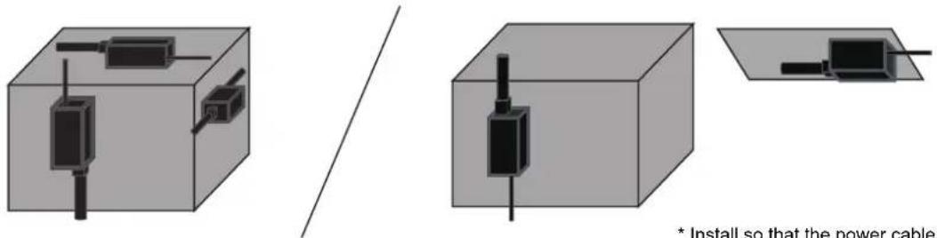
Installation not allowed
* Install so that the power cable that connects to 120 V AC does not face upward.
REQUIREMENT
Do not install in the following locations.
- Locations with high humidity or water
- Dusty locations
- Locations in direct sunlight and locations subject to high temperatures
- Locations within 3.28' (1 m) from televisions or radios
- Outdoors, under awnings, or other locations exposed to rain and dew
3-3. Power, Signal, and Earth Line Connections
Connect the power, signal and earth lines to the specified terminal blocks.
REQUIREMENT
Attach round crimp terminals to all TCC-LINK 1, TCC-LINK 2, and RS-485 wiring, and tighten the screws securely. After tightening, check that the wiring cannot come out.
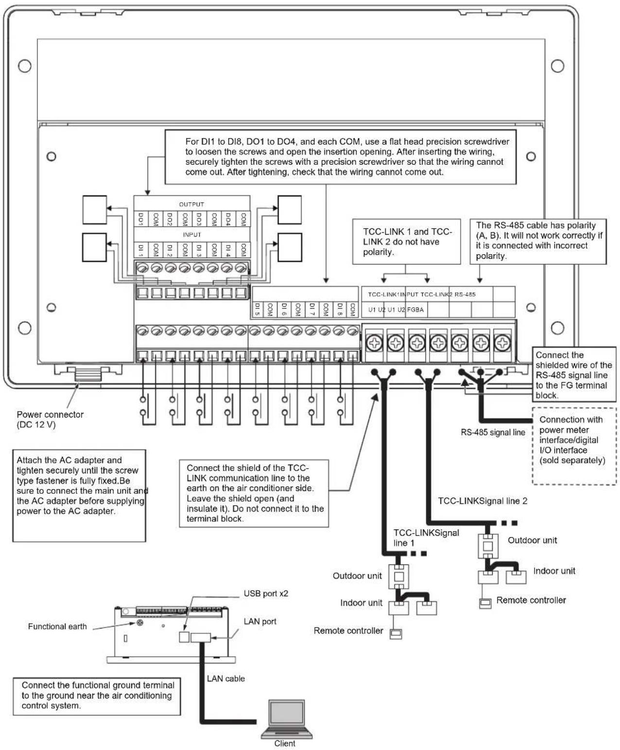
TCC-LINK communication line stripping length
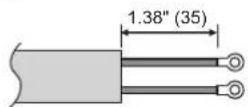
RS-485 cable wire stripping length
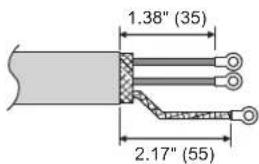
Digital I/O cable stripping length
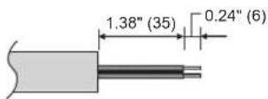
Unit: inch (mm)
Attach a round crimp terminal to each wire of the power line and signal line.
Loosen the screws with a screwdriver, insert the digital I/O cable, and tighten the screws securely.
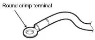
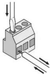
natural_image
Diagram of a mechanical component with arrows indicating force or movement (no text or symbols)Termination resistance setting
- RS-485 termination resistance setting ....Set at both ends of the RS-485 communication line. Set one end at the main unit and the other end at the interface. The termination resistance of the main unit is already set as a factory default. Refer to the interface installation manual to set the termination resistance of the interface.
- TCC-LINK termination resistance setting ....Set on the air conditioner. The TCC-LINK termination resistance is not set in the main unit. Leave "open".
Shield grounding process
- RS-485 cable wire shielded wire .... Connect to the FG terminal block.
- TCC-LINK communication cable shielded wire .....When using the air conditioning control system with one unit, open the shielded wire of the TCC-LINK communication cable and perform insulation processing.
When using the air conditioning control system with multiple units, connect the shield of the TCC-LINK communication line to the closed end and open the shield at the final end of the air conditioning control system to perform insulation processing.
Perform TCC-LINK communication line shield grounding on the air conditioner side.
REQUIREMENT
- Be sure to install a circuit breaker or all-pole isolating switch (with a contact breaking distance of at least 0.12" (3 mm)) on the primary side of the power supply.
- Fasten the screws to the terminal block with torque of 0.37 lbf·ft (0.5 N·m).
■ Connection to External Devices
Example of connection to external equipment which is connected to digital input/output terminal.
| Name | I/O Item | Air conditioning control system side External device side | ||
| I/O conditions Terminal name Circuit example I/O conditions | ||||
| DO1 Output common | State output | Contact permissible voltage/current24 V DC/35 mA | 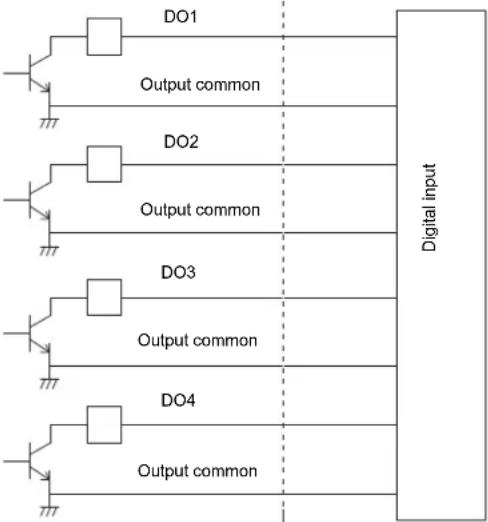 | Wiring length: Within 328.1' (100 m) |
| DO2 Output common | ||||
| DO3 Output common | ||||
| DO4 Output common | ||||
| DI1 Input common | Control input | No-voltage contact A Pulse or static* No-voltage contacts compatible with very small current should be selected5 V DC/3 mA | 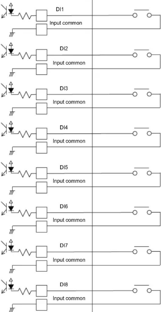 | Pulse width: 50 msec or more Wiring length: Within 328.1' (100 m) |
| DI2 Input common | ||||
| DI3 Input common | ||||
| DI4 Input common | ||||
| DI5 Input common | ||||
| DI6 Input common | ||||
| DI7 Input common | ||||
| DI8 Input common | ||||
* Wire the cables so that the user does not touch the power supply directly.
* On the external device side, use a basically insulated power circuit and place it in a location where the user cannot touch it.
■ Wiring connections
This section shows wiring connection examples with the indoor units, power meter interface, digital I/O interface, and remote monitoring PC.
Air conditioning unit group settings
- Indoor units can be set together for each group unit.
- There is a TCC-LINK 1 and a TCC-LINK 2 for each TCC-LINK communication line. There are 64 groups in each line, and there are 128 groups and 128 zones for TCC-LINK 1 and TCC-LINK 2 together.
Interface connection
Connect the power meter interface and the digital I/O interface to the RS-485 cable line. For details of the connection method refer to the interface installation manual.
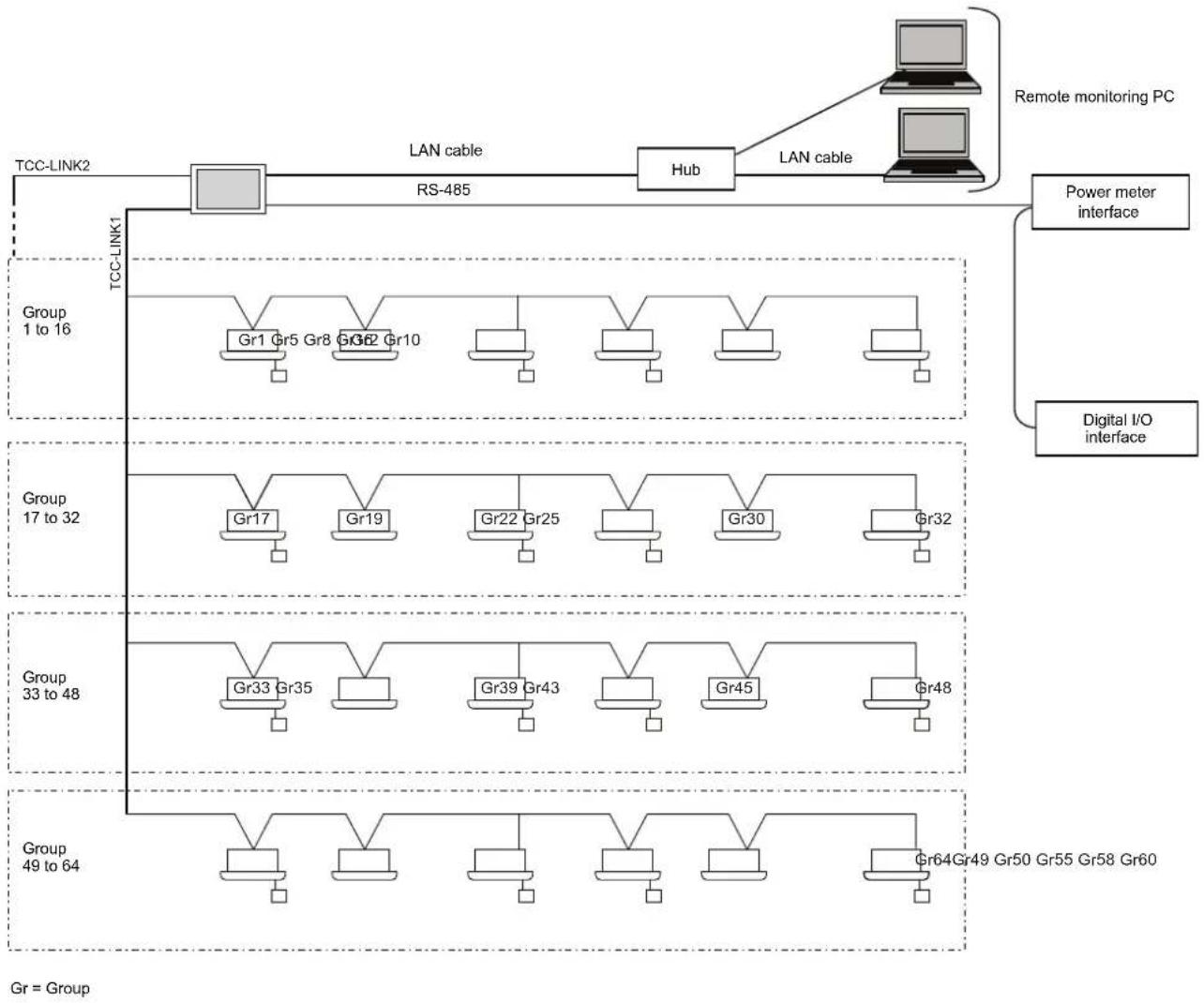
flowchart
graph TD
    subgraph TCC-LINK2
        A["Hub"] -->|LAN cable| B["RS-485"]
        B --> C["Power meter interface"]
        D["TCC-LINK1"] --> E["Group 1 to 16"]
        E --> F["Gr1 Gr5 Gr8 Gr9 Gr10"]
        F --> G["Digital I/O interface"]
        H["Group 17 to 32"] --> I["Gr17"]
        I --> J["Gr19"]
        J --> K["Gr22 Gr25"]
        K --> L["Digital I/O interface"]
        M["Group 33 to 48"] --> N["Gr33 Gr35"]
        N --> O["Gr39 Gr43"]
        O --> P["Digital I/O interface"]
        Q["Group 49 to 64"] --> R["Gr49 Gr50 Gr55 Gr58 Gr60"]
    end
    S["Remote monitoring PC"] --> T["Hub"]
    T --> U["Power meter interface"]
    style TCC-LINK2 fill:#f9f,stroke:#333
    style TCC-LINK1 fill:#ccf,stroke:#333
    style Digital I/O interface fill:#cfc,stroke:#333
NOTE
Set the termination resistance of TCC-LINK 1 and 2 at the air conditioner.
When you remove the rear panel of this Unit, there is SW100 which is the termination resistance of TCC-LINK 1 and 2. In both cases, please use in the "Open": OFF state.
Network Configuration Guide
Model name:
BMS-CT1280UL

Prohibited
Never connect the Touch Screen Controller to the Internet.
We assume no responsibility for any problems resulting from connection to the Internet.
Only local area connection is allowed for the Touch Screen Controller.
This guide describes the setting procedure for connecting the Touch Screen Controller to your personal computer (abbreviated to "PC" hereinafter) via the network.
PC operation to monitor and control air conditioners is detailed in the Owner's Manual.
1. System configuration of PC
The client PC to be connected must meet the following system configuration conditions so that the Touch Screen Controller operates normally.
Must be either of the following
- Windows 8.1
- Windows 10
• Screen resolution 1366 × 768 pixels or more
Must be either of the following
- Internet Explorer 11
- Google Chrome
- Microsoft Edge
2. Connecting LAN cable
Connect the LAN cable to the LAN1 connector on the Touch Screen Controller.
3. Client PC settings
3-1. Setting IP address
1) Log on to the system with the PC administrator's account.
2) Click [Start] -> [Control Panel]. (Fig.1)
Fig.1
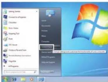
3) Click [Network and Sharing Center]. (Fig.2)
Fig.2
4) Click "Local Area Connection" of View your active networks. (Fig.3)
Fig.3
5) Click [Properties] in the Local Area Connection Status window. (Fig.4)
Fig.4
6) Select the "Internet Protocol Version 4 (TCP/IPv4)" checkbox, and click [Properties]. (Fig.5)
Fig.5
7) Select the "Use the following IP address:" radio button, and set as follows: IP address: 192.168.2.*** (**: Excluding 80) Subnet mask: 255.255.255.0. Then click [OK]. (Fig.6)
Fig.6
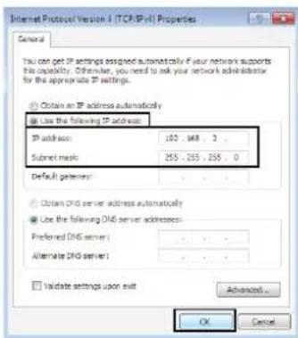
8) Close all the windows.
3-2. Setting browser
1) Start Internet Explorer.
2) Click the [Tools] button.
3) Choose "Internet Options" from the pull-down menu.
4) Click the "Connections" tab. (Fig.1)
Fig.1
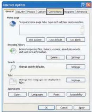
5) Click [LAN settings]. (Fig.2)
Fig.2
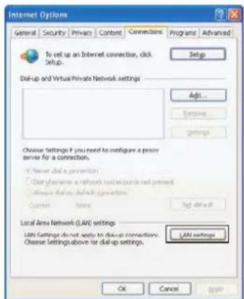
6) Clear the "Use a proxy server for your LAN" checkbox (Fig.3) or select the "Bypass proxy server for local addresses" checkbox (Fig.4), and then click [Advanced].
Fig.3
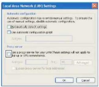
Fig.4
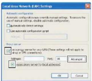
Add "192.168.2.80" to the "Do not use proxy server for addresses beginning with:" field. (Fig.5)
Fig.5
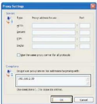
Now the configuration operations are completed. For the subsequent operations, refer to the Owner's Manual.
Owner's Manual
Touch Screen Controller
Model Name
BMS-CT1280UL
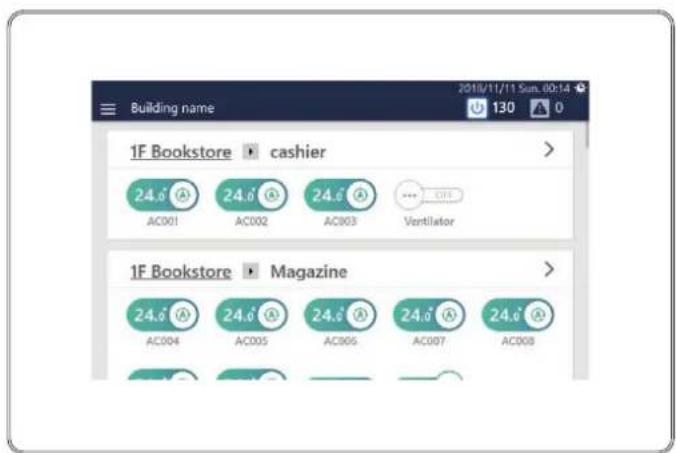
- Thank you for purchasing this air conditioning control system.
- In order to use this product safely and correctly, please read this operation manual carefully before use and make sure that you fully understand the contents.
In particular, please be sure to read the "Safety Precautions". - After reading this manual, be sure to keep it in a place where the operator of the Unit can always view it.
Contents
1 Quick Start Guide 6
2 Safety Precautions 7
3 Operating method and screen structure. 9
Touch Panel Operation Method....9
Screen Structure 10
4 Before Usage.... 11
Air Conditioning System Configurations ..... 11
Control Target Devices....12
About the Main Screens 13
Home 13
Screen description 13
Group control screen ([CONTROL] tab) 16
How to display the screen 16
Screen description 17
Individual control screen ([CONTROL] tab) 18
How to display the screen 18
Screen description 19
5 Perform initial settings.... 21
Unit Settings 21
Settings for Remote Monitoring with a PC 21
System diagram 21
Unit settings 22
PC settings 22
Settings 22
Operating Environment. 22
Install the software 23
Settings when Using Report Creation Software....24
Unit settings 24
PC settings 24
Settings when Using the PC Software Data Analyzer 24
Unit settings 24
PC settings 24
6 Basic Usage.... 25
Start/Stop Operation 25
Overall air conditioning system operation method 25
Group unit operation method 26
Operation method in units of air conditioner or ON/OFF unit 27
Change the Air Conditioning Settings
(ON/OFF/Mode/Wind direction/Fan Speed/Set temp.) 28
Group unit operation method 28
Air conditioner unit operation method.... 31
Set the Operation Schedule 33
Screen description 33
Group screen 33
Individual control screen.... 34
Create a new Week Schedule 35
Create a new Particular Timer setting 37
Monitor the Overall Air Conditioning System....39
7 Various Functions.... 40
Local Remote Controller Lock 40
Set Operation Details 42
Turn ON/OFF the ventilation function (Ventilation → ON/OFF) 44
Set Ventilation Mode (Ventilation → Mode) 44
Setting the ventilation fan speed (Ventilation → Fan speed) 44
Check the output status of the air conditioner(s) (Power Level). 45
Check the indoor temperature detected by the outdoor unit (Outdoor temp.) 45
Erase FILTER Sign (Filter sign reset).... 45
Set Middle COOL (Soft Cooling) 45
Control air conditioner power (Energy saving ratio [%]) 46
Release Thermo OFF (Forced Thermo OFF) 46
Configure and confirm the Return Back settings (Return Back).... 46
Monitor demand control of outdoor unit (Power peak cut) 46
Change to energy saving temperature (Eco Temperature Shift) 47
Set the temperature change range (Set temp. range limit) 47
Change the Operating Schedule 48
Change the details of the Week Schedule 48
Change the details of the Particular Timer setting 50
Setting items list 52
Delete the operation schedule 54
Confirm the Operation Time....55
Group screen 55
Individual control screen.... 55
8 Administrator menu 56
Restrict Operation of the Touch Screen Controller (Operation Lock) ..... 56
Confirm Alarm History (Alarm history) 57
Confirm the Power consumption on a Graph (Power consumption) ..... 58
[Functions] Menu Settings....59
How to display the [Functions] menu 59
Release demand control of outdoor unit (Release power peak cut).... 59
Set demand control schedule of outdoor unit (Power peak cut schedule) 60
Add/change Power peak cut schedule.... 60
Delete an Power peak cut schedule.... 62
Restrict operation mode (Operation mode restriction) 62
Restart the Unit (System reboot) 62
Set the operating schedule or the power peak cut schedule (Scheduler Operation) ..... 63
Output data to a USB memory stick (Output to USB memory).... 63
[Initial setting] Menu Settings 63
How to display the [Initial setting] menu 63
Set the screen display (Display).... 64
Set the current date and time (Clock and calendar).... 64
Set icons of devices other than air conditioners (Icon).... 65
Set the screen theme (Theme).... 65
Set an account for remote operation (User Account) 66
Add/change user account.... 66
Delete a user account.... 67
Set the operation lock level (Operation lock) 68
Set the IP address of the Touch Screen Controller (IP Address)....69
Set alarm email destination (Alarm email address) 70
Change the area set for an indoor unit (Indoor unit area setting)....71
Set the name of an indoor unit (Indoor unit name setting) 72
Set the area name (Area name setting) 72
Set the screen brightness (Backlight)....73
9 Remote monitoring using a PC 74
Log in to Remote Control Software 74
Log out from Remote Control Software 74
Exit Remote Control Software 75
10 Power allocation.... 76
Electric Power Allocation System that can be Used with this Unit ..... 76
Power Allocation System 77
Set the summation date of the power allocation data (Automatic Meter-Reading) ..... 77
Sum data for power allocation as necessary (Manual Meter-Reading) 78
How to use the power allocation system 78
11 Troubleshooting....79
12 Useful information 82
13 Appendix....82
Specifications 82
Detailed specifications 82
Function list 83
Glossary....84
List by Lock Level/Level....84
14 Warranty and after-sales service 86
About the Warranty....86
About After-Sales Service 86
Contact for after-sales service (Information) 86
OSS License 87
1Quick Start Guide
| Basic Usage | ||
| To start/stop the air conditioner(s) | → "Start/Stop Operation" (P.25) | |
| To change the set temperature | → "Change the Air Conditioning Settings (ON/OFF/Mode/Wind direction/Fan Speed/Set temp.)" (P.28) | |
| To change the Mode (Cool/Heat/Auto/Dry/Fan) | → "Change the Air Conditioning Settings (ON/OFF/Mode/Wind direction/Fan Speed/Set temp.)" (P.28) | |
| To check whether you have forgotten to turn off the air conditioner(s) | Batch ON/OFF screen | → "Monitor the Overall Air Conditioning System" (P.39) |
| To check for current alarms Alarm history screen | → "Monitor the Overall Air Conditioning System" (P.39) | |
| Advanced Usage Please use the following functions as necessary. | ||
| To set start/stop timer | → "Set the Operation Schedule" (P.33) | |
| To configure and confirm the energy saving settings | Return Back | → "Configure and confirm the Return Back settings (Return Back)" (P.46) |
| Eco Temperature Shift | → "Change to energy saving temperature (Eco Temperature Shift)" (P.47) | |
| Change Temperature Range | → "Set the temperature change range (Set temp. range limit)" (P.47) | |
| Save Mode | → "Control air conditioner power (Energy saving ratio [%])" (P.46) | |
| Schedule settings | → "Set the Operation Schedule" (P.33) | |
| Power peak cut schedule | → "Set demand control schedule of outdoor unit (Power peak cut schedule)" (P.60) | |
| To operate the Total Heat Exchange Unit | → "Turn ON/OFF the ventilation function (Ventilation → ON/OFF)" (P.44) | |
| To cancel the FILTER Sign after filter cleaning | → "Erase FILTER Sign (Filter sign reset)" (P.45) | |
| To connect with a PC that has the PC software Data Analyzer installed and display the usage of energy | Connect with the PC that has the PC software Data Analyzer installed and display the energy usage | → "Settings when Using the PC Software Data Analyzer" (P.24) |
| IP Address Setting | → "Set the IP address of the Touch Screen Controller (IP Address)" (P.69) | |
| Output to USB memory | → "Output data to a USB memory stick (Output to USB memory)" (P.63) | |
| To connect with a PC that has Report Creation Software installed and display the power usage report | Connect with a PC that has Report Creation Software installed and display the power usage report | → "Electric Power Allocation System that can be Used with this Unit" (P.76) |
| Automatic Meter-Reading | → "Set the summation date of the power allocation data (Automatic Meter-Reading)" (P.77) | |
| Manual Meter-Reading | → "Sum data for power allocation as necessary (Manual Meter-Reading)" (P.78) | |
| IP Address Setting | → "Set the IP address of the Touch Screen Controller (IP Address)" (P.69) | |
| To output the daily and monthly report files, the alarm files, and the setup files by USB | → "Output data to a USB memory stick (Output to USB memory)" (P.63) | |
2 Safety Precautions
This section explains safety precautions you must follow in order to prevent harm to the user and other persons and damage to property.
"Display Description" explains the classification of the degree of harm or damage that may occur if the unit is handled incorrectly, while "Symbol Description" indicates the meanings of symbols.
Display Description Symbol Description
 WARNING WARNING | Indicates "Content that is expected to result in death or serious injury (*1) to the user in the case of incorrect handling". |  | ⊗ indicates prohibited actions. Specifically prohibited contents are indicated with a picture and/or text in or near the symbol. |
 CAUTION CAUTION | Indicates "Content that is expected to result in minor injury (*2) to the user or damage to property (*3) in the case of incorrect handling". |  | ● indicates instructions which must be followed. The actual contents of the instructions are indicated with a picture and/or text in or near the symbol. |
* 1: Serious injury refers to lasting after effects such as blindness, injury, burns (high temperature / low temperature), electric shock, bone fracture, or poisoning, etc. and injuries that require hospitalization/long-term outpatient treatment.
* 2: Minor injury refers to injuries, burns, or electric shocks, etc. that do not require hospitalization or long-term outpatient treatment.
* 3: Damage to property refers to extended damage related to houses, household goods, livestock, or pets, etc.
indicates prohibited actions. Specifically prohibited contents are indicated with a picture and/or text in or near the symbol.
indicates instructions which must be followed. The actual contents of the instructions are indicated with a picture and/or text in or near the symbol.

WARNING
Installation Precautions
 Request installation Request installation | Ask the dealer from whom you purchased the unit or a professional for installation work.Installation requires specialised technical expertise.If you attempt to perform installation work yourself and perform the work incorrectly, it may cause fire, electric shock, or injury. |  Use specified products Use specified products | Use a designated TOSHIBA air conditioner.Please use a designated TOSHIBA air conditioner. Using products other than specified may cause fire, electric shock, or water leakage. Also, please ask a professional for installation work. |
Usage Precautions
 Prohibited Prohibited | Do not operate the switches with wet hands.Doing so may cause electric shock or failure. |  Prohibited Prohibited | Do not wet the Air Conditioning Control System.Please be careful not to get the Air Conditioning Control System wet.Doing so may cause fire, electric shock, or failure. |
 Compulsory Compulsory | Turn off the power if anything is abnormal (burnt odour etc.).Continued use may cause fire or electric shock.Please ask the dealer from whom you purchased the product. |  Compulsory Compulsory | Do not use a power source other than the specified model.Using a power source other than the specified model may cause fire or failure.Please use 120 V AC. |
Relocation/Repair Precautions
 Prohibited Prohibited | Do not remodel.Doing so may cause fire or electric shock. |  Request Request | Please ask the dealer from whom you purchased the unit for repair.Faulty repair may cause fire or electric shock. |
 Request relocation Request relocation | Contact a specialist or the dealer from whom you purchased the unit to relocate and re-install the air conditioner.Faulty installation may cause fire, electric shock or injury. | ||
Use specified products

CAUTION
Installation Precautions
 Check the installation location Check the installation location | Do not install in areas with high humidity or vibration.Doing so may cause a failure. |
 Check the installation location Check the installation location | Do not install in areas where noise is generated.Doing so may cause malfunction. |


Usage Precautions
 Prohibited Prohibited | Do not drop the product or apply strong shock.Doing so may cause a failure. |
 Instructions Instructions | When cleaning and checking, turn off the earth leakage breaker.Failing to do so may cause injury. |

If anything is abnormal turn off the power
Do not install in direct sunlight or near heat sources. Doing so may cause a failure.
Do not install the air conditioner in a place where combustible gas may leak. Gas leaking and accumulating around the product may cause a fire.
If anything is abnormal, stop operation and turn off the original power supply, then contact the dealer from whom you purchased the unit.
Continued operation with an abnormality may cause fire or electric shock.
3Operating method and screen structure
Touch Panel Operation Method
Explains the basic touch panel operation method.
Tap
Touch your finger lightly on the screen and release it immediately.
natural_image
Illustration of a hand pointing at a glowing red-orange button on a digital tablet screen (no text or symbols)Swipe
Touch your finger lightly on the screen and move it in the desired direction.
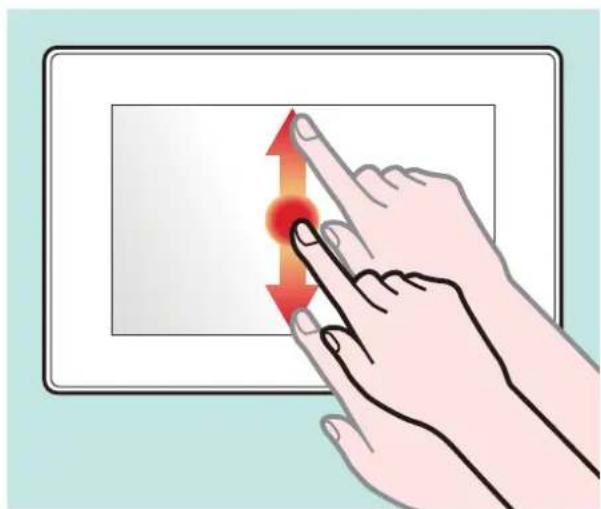
natural_image
Illustration of a hand pressing a button on a digital display (no text or symbols)Drag
Tap an object on the screen, hold your finger down, and move.
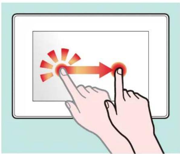
natural_image
Illustration of two hands interacting with a digital display showing a red arrow and starburst effect (no text or symbols)Flick
Touch the screen with your finger and move your finger quickly up, down, to left or the right.
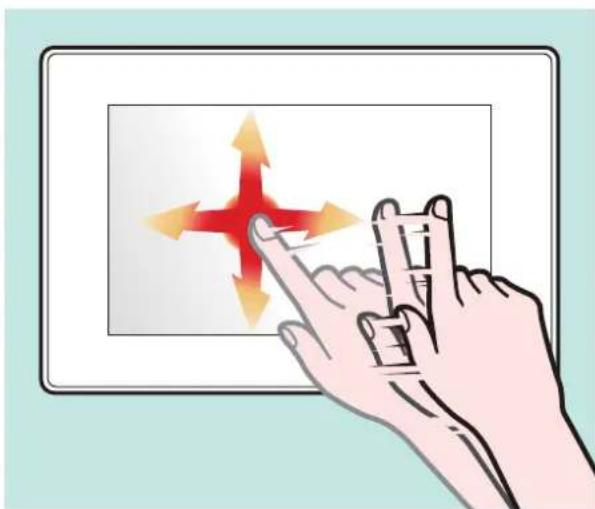
natural_image
Illustration of a hand interacting with a digital display showing a red cross and arrows (no text or symbols)Screen Structure
The main screen structures used by this Unit are as follows. The screen can be switched by tapping (or flicking in some cases).
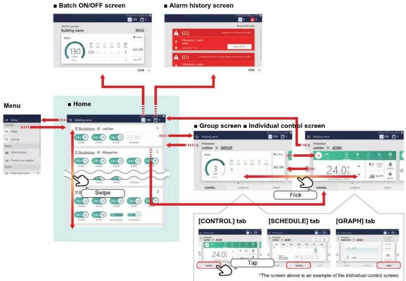
flowchart
graph TD
    subgraph Home
        A["Menu"] --> B["Menu Name"]
        B --> C["Building Name"]
        C --> D["Group Screen"]
        D --> E["Individual Control Screen"]
    end

    subgraph Individual Control Screen
        F["Menu"] --> G["Menu Name"]
        G --> H["Group Screen"]
        H --> I["Individual Control Screen"]
    end

    subgraph Control Panel
        J["Control"] --> K["[CONTROL"] tab]
        K --> L["[SCHEDULE"] tab]
        L --> M["[GRAPH"] tab]
        N["Tap"] --> O["The screen above is an example of the Individual control screen."]
    end

    style Home fill:#f9f,stroke:#333
    style Individual Control Screen fill:#ccf,stroke:#333
Each display is an example screen. The display content varies with the usage environment settings.
| Home screen | You can check the operation status of the air conditioner(s) and ON/OFF unit in a list. You can also start/stop individual operation. (P.13) | |
| Group screen | You can check/change the settings in group units. The group screen consists of three tabs: "CONTROL", "SCHEDULE" and "GRAPH". (P.16) | |
| Individual control screen | You can check/change the settings of the air conditioner(s) and ON/OFF unit individually. The individual control screen consists of three tabs: "CONTROL", "SCHEDULE" and "GRAPH". (P.18) | |
| Batch ON/OFF screen | You can check the operation status of the whole air conditioning system numerically. You can also start/stop the operation of the whole air conditioning system and configure the detailed settings. (P.39) | |
| Alarm history screen | You can confirm alarms that are occurring in the whole air conditioning system in a list. (P.39) | |
| [CONTROL] tab You can check the detailed operation status. | ||
| [SCHEDULE] tab | You can change the settings such as ON/OFF. (P.25) | |
| [GRAPH] tab | Group screen | You can check the operation time in group units. (P.55) |
| Individual control screen | You can check the operation time in air conditioner or ON/OFF unit in units. (P.55) | |
| Menu | You can configure settings for administrators such as screen display change and demand control. (P.56) | |
* Although temperature is indicated in [°C] in the figures used in this manual, the initial temperature is displayed in [°F] on this software.
4Before Usage
Air Conditioning System Configurations
The system configurations that this Unit can control are as follows:
All
Set all air conditioners at once.
128 groups, up to a total of 128 units
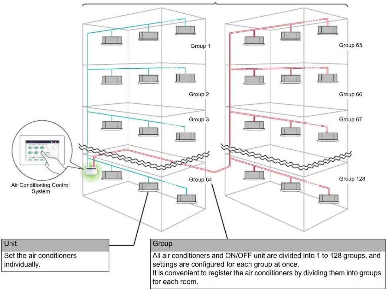
flowchart
graph TD
    A["Unit"] --> B["Set the air conditioners individually."]
    B --> C["Group 64"]
    C --> D["Group 128"]
    D --> E["Group 65"]
    E --> F["Group 67"]
    F --> G["Group 66"]
    G --> H["Group 65"]
    H --> I["Group 64"]
    I --> J["Group 3"]
    J --> K["Group 2"]
    K --> L["Group 1"]
    style A fill:#f9f,stroke:#333
    style B fill:#ccf,stroke:#333
    style C fill:#cfc,stroke:#333
    style D fill:#fcc,stroke:#333
    style E fill:#cff,stroke:#333
    style F fill:#ffc,stroke:#333
    style G fill:#ffc,stroke:#333
    style H fill:#ffc,stroke:#333
    style I fill:#cfc,stroke:#333
    style J fill:#cfc,stroke:#333
    style K fill:#cfc,stroke:#333
    style L fill:#cfc,stroke:#333
    style_M["Air Conditioning Control System"] --> N["User Interface Display"]
    N --> O["Device Icon"]
    O --> P["Control Unit"]
    P --> Q["Group 1"]
    P --> R["Group 2"]
    P --> S["Group 3"]
    P --> T["Group 64"]
    P --> U["Group 128"]
- There are three units that can be controlled: All, Group, and Unit.
- The maximum number of groups (Floor/Tenant/Area combinations) that can be controlled is 128.
- The maximum number of units that can be controlled (air conditioner(s) and ON/OFF unit) is 128 for air conditioners and 60 for ON/OFF unit.
Control Target Devices
In this Unit, the following devices can be controlled and monitored.
| Device names shown in this manual Target devices | ||
| Air conditionerYou can set air conditioning and heating operation(128 units) | ·Multi air conditioners for buildings (Ceiling cassette, ceiling embedded, ceiling hanging, air to air heat exchanger with coil, etc.) ·Custom air conditioners for stores and offices ·Package air conditioners for facilities ·Hot Water Module (* For use outside Japan only) ·DX-Coil Interface TA type (* For use outside Japan only) |  |
| ON/OFF unitYou cannot set air conditioning or heating operation (Operation can be turned ON/OFF.)(60 units) | ·Air to Air Heat Exchanger |  |
| ·General purpose device control interface ·External device (DI/DO) (Air to Air Heat Exchanger, Lighting, Ventilation fan, etc.) |  | |
 | ||
 | ||
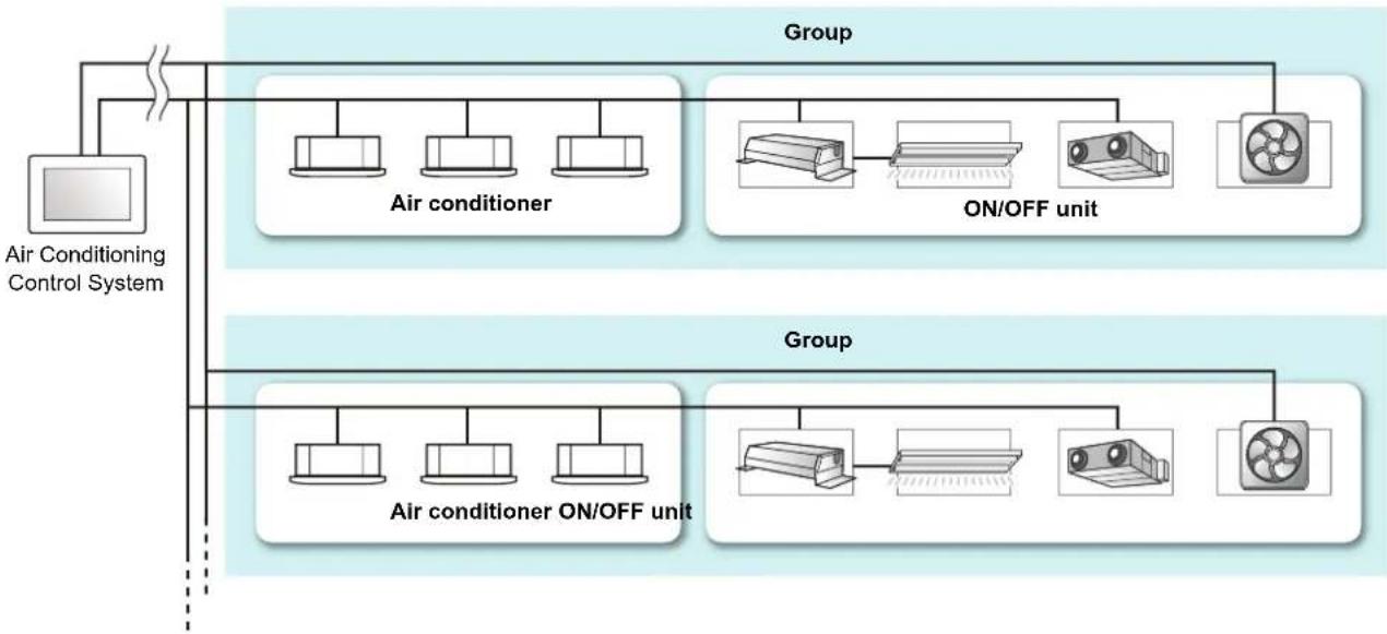
flowchart
graph TD
    A["Air Conditioning Control System"] --> B["Group"]
    B --> C["Air conditioner"]
    B --> D["ON/OFF unit"]
    B --> E["Group"]
    E --> F["Air conditioner ON/OFF unit"]
    E --> G["Group"]
    G --> H["ON/OFF unit"]
    G --> I["Group"]
About the Main Screens
This section explains the home screen and the [CONTROL] tab of the group screen/individual control screen.
NOTE
The language and display colors of the screen differ depending on the language and theme settings. The screens shown in the manual use the [English] language setting and the [Type A] theme setting. For details of the theme settings, refer to "Set the screen theme (Theme)" (P.65).
Home
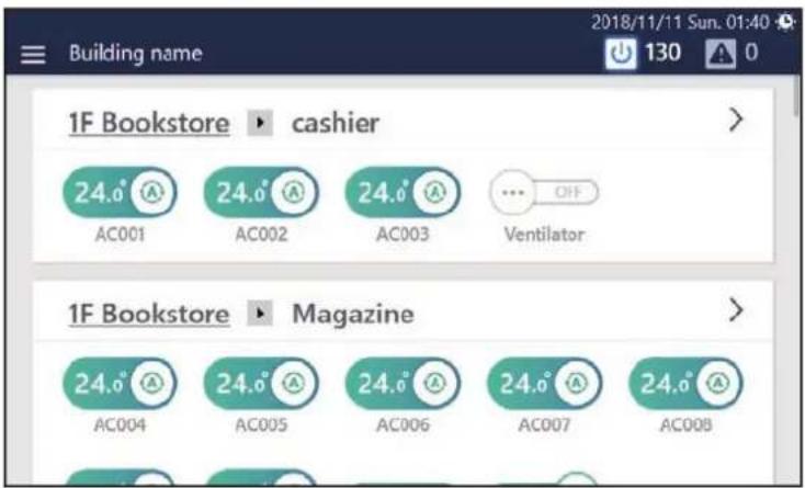
Screen description
Switches for all air conditioners and ON/OFF unit are displayed for each group. You can change the group displayed by scrolling the screen.
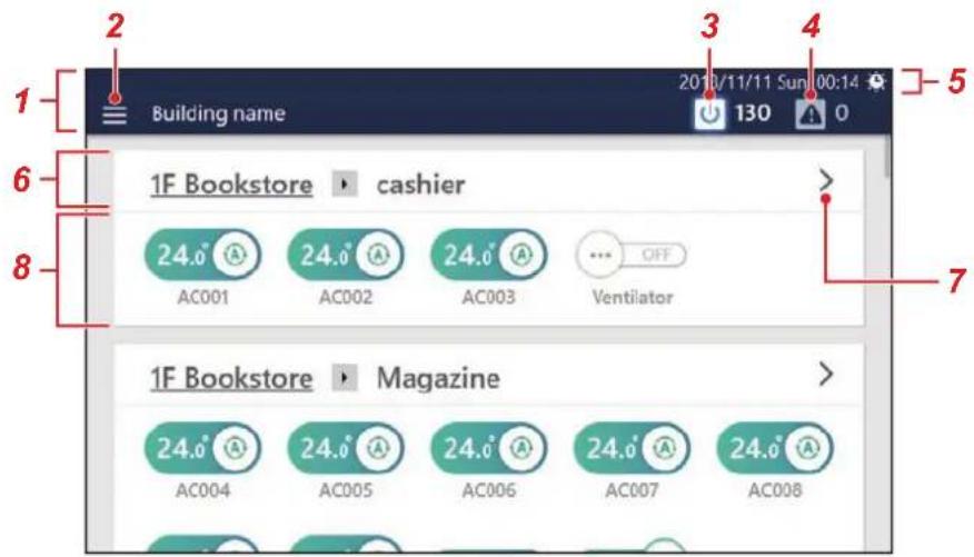
| No. Name (Icon) Functions | |||
| 1 | Header area | It is displayed even on screens other than the home screen. The operation content is common to each screen. | |
| 2 | Menu button (Tap to display the menu. | You can display various reports and detailed settings for the Unit.●NOTEThe display content of the menu may partially differ depending on the conditions. | 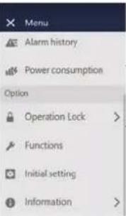 |
| 3 | ON/OFF meter button (Tap to display the | batch ON/OFF screen. (P.39)Lights up when there is an air conditioner or ON/OFF unit in operation. | |
| 4 | Alarm button (Tap to display the alarm history screen. (P.39)Lights up red when an alarm has occurred. | ||
| 5 | Status display section | Displays the current date and time. Also, the following will be displayed depending on the status and settings of the air conditioning system. | |
| Displays when a demand signal is detected. | |||
| Displays during demand control of an outdoor unit. (P.60) | |||
| Displays when you operate remotely from a computer. (P.74) | |||
| Displays while outputting data to a USB memory stick. (P.63) | |||
| Displays when the daylight saving time (summer time) setting is ON. (P.64) | |||
| 6 | Group name display section | Displays the name of the group that displays the switch (the name of the group to which the displayed switch belongs).Tap the underlined name in the group name to display the drop-down menu.You can jump to other groups. | |
| 7 | "FORWARD" button ( ) Tap to display the group screen. (P.16) | ||
| No. Name (Icon) Functions | ||
| 8 | Switch | The air conditioner or ON/OFF unit switch registered in each group is displayed, and the name is displayed below the switch. |
 Displays the operation status of the air conditioner(s).24.6®means operating state. The set temperature is displayed on the left and the operation mode is displayed on the right. Drag or flick to the left to stop the operation.*is the stopped state. Only the set operation mode is displayed. Drag or flick to the right to start the operation.Tap the overall switch to switch to the [CONTROL] tab on the individual control screen. (P.18) Displays the operation status of the air conditioner(s).24.6®means operating state. The set temperature is displayed on the left and the operation mode is displayed on the right. Drag or flick to the left to stop the operation.*is the stopped state. Only the set operation mode is displayed. Drag or flick to the right to start the operation.Tap the overall switch to switch to the [CONTROL] tab on the individual control screen. (P.18) | ||
 Displays the operating condition of the air conditioner.Operation of the air conditioner(s) is locked. (P.56) Displays the operating condition of the air conditioner.Operation of the air conditioner(s) is locked. (P.56) | ||
 Alarm in progress. Tap to switch to the [CONTROL] tab on the individual control screen and check the details of the alarm. (P.20)Operation is impossible due to power outage (hibernation state). Alarm in progress. Tap to switch to the [CONTROL] tab on the individual control screen and check the details of the alarm. (P.20)Operation is impossible due to power outage (hibernation state). | ||
 Displays the operation status of the ON/OFF unit.Drag left or right to change the operation status. Displays the operation status of the ON/OFF unit.Drag left or right to change the operation status. | ||
 Displays the operation status of the ON/OFF unit.The operation status cannot be changed.The Unit is locked or output control cannot be performed. Displays the operation status of the ON/OFF unit.The operation status cannot be changed.The Unit is locked or output control cannot be performed. | ||
 Displayed when the FILTER Sign appears. Displayed when the FILTER Sign appears. | ||
| [CAAB]Displayed during operation preparation. | ||
 Displayed during heating preparation. Displayed during heating preparation. | ||
| [HKDA]Displayed when the output of the air conditioner is limited. | ||
Group control screen ([CONTROL] tab)
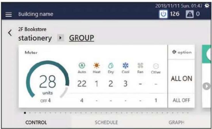
How to display the screen
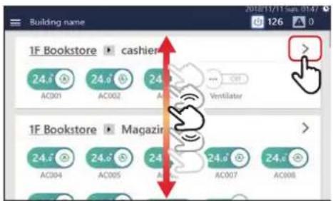
1 Scroll the home screen to display the group you want to change the settings for, then tap >
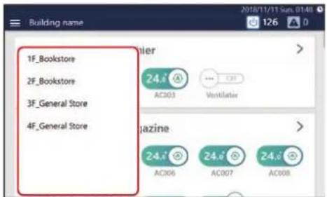
NOTE
You can jump to another group in the drop-down menu displayed by tapping the group name.
The [CONTROL] tab of the group screen is displayed.
Screen description
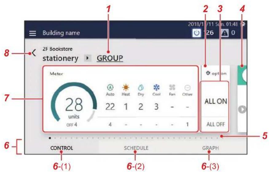
| No. | Name (Icon) Functions | |
| 1 | Group name Displays the name of the currently displayed group.Tap to display the drop-down menu. You can switch the display to the individual control screen for another air conditioner or ON/OFF unit registered in the group.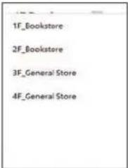 | |
| 2 | Setting | You can change overall settings of the group such as Mode, set temperature, air direction, and fan speed simultaneously. (P.28) |
| 3 | ALL ON/ALL OFF You can turn the whole group ON/OFF simultaneously. (P.26) | |
| 4 | Next screen | Tap to display the individual control screen of the air conditioner or ON/OFF unit registered in the group. You can flick the group screen to display it. |
| 5 | Display position | Only the number of air conditioners or ON/OFF unit registered in the group is displayed. For the currently displayed screen, is displayed. |
| 6 | [SWITCH] tab Tap to switch to the " | 6-(1)", "6-(2)" or "6-(3)" tab of the group screen. |
| 7 | Run The ON/OFF meter on the left side can be used to check the total number of units operated in the group.On the right side you can check the number of units in each operation mode. The upper row shows the number of units in operation and the lower row shows the number of units stopped. If there are devices that do not have an operation mode, they will be displayed in [Other]. | |
| 8 | "BACK" button( )Returns to the Home. | |
Individual control screen ([CONTROL] tab)
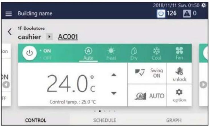
How to display the screen
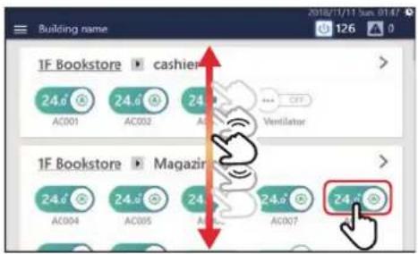
1 Scroll the home screen, display the air conditioner or ON/OFF unit that you want to change the settings for, then tap the switch
The [CONTROL] tab of the individual control screen is displayed.
Screen description
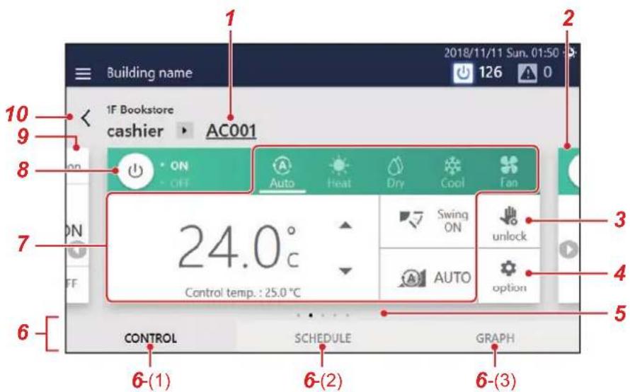
Each display is an example of the screen in the case of an air conditioner.
The display contents varies with use environment settings.
| No. | Name (Icon) Functions | |
| 1 | Group name | The name of the air conditioner or ON/OFF unit currently displayed is shown.Tap to display the drop-down menu. You can switch the display to the group screen or another air conditioner or ON/OFF unit registered in the group. |
| 2 | Next screen | Tap to display the individual control screen for other air conditioners or ON/OFF unit registered in the group. You can also flick and display the individual control screen being displayed. |
| 3 | Lock setting of remote control | You can restrict the operating range of the local remote controller of the air conditioner(s) or ON/OFF unit. (P.40)If it is not restricted, [ ] is displayed. If there are restricted items, [ ] is displayed. |
| 4 | option You can set or confirm the details of the operation method. (P.42) | |
| 5 | Display position | Only the number of devices registered in the group is displayed. For the currently displayed screen, is displayed. |
| 6 | [SWITCH] tab Tap to switch to the "6-(1)", "6-(2)" or "6-(3)" tab of the individual control screen. | |
| 7 | Setting area | You can change basic settings such as operation mode, set temperature, air direction, and fan speed. (P.31) |
| 8 | ON/OFF Tap to switch between ON/OFF. | |
| 9 | Previous screen | Tap to display the individual control screen for other air conditioners or ON/OFF unit registered in the group. You can also flick and display the individual control screen being displayed. The group screen appears at the beginning. |
| 10 | "BACK" button( < ) | Returns to the home screen. |
NOTE
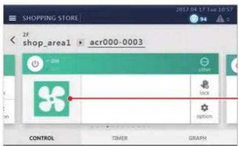
- For ON/OFF unit, only configurable items are displayed.
Icons are displayed only when they are registered. (P.65)
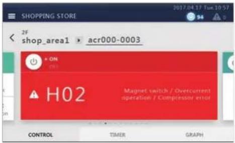
- If an error occurs, an alarm code is displayed. Operation other than operation ON/OFF is not possible.
• Operation is impossible due to power outage (hibernation state).
5Perform initial settings
Unit Settings
Have service personnel perform the following work.
1 Check the installation and wiring of the main unit
Follow the installation instructions to complete the installation and wiring work.
2 Check the wiring between the remote controller, indoor unit, and outdoor unit
Check that the address from the remote controller to the Unit is correct, and switch ON/OFF, Cool/Heat and confirm that operation is normal.
3Create a local setting file with the setting file creation software
Input necessary information based on local air conditioner information and display language settings, etc. into a PC on which the setting file creation software is installed to create a local settings file.
4Upload the local settings file
Connect the Unit to the PC via LAN and upload the local settings file.
While uploading, the Unit restarts.
5 Confirm the setting contents
Check that the screen display of the Unit is set according to the local settings file, perform ON/OFF, and confirm that the Unit operated on the screen matches the Unit that actually starts to operate.
Settings for Remote Monitoring with a PC
You can monitor and control the Unit by accessing it from a PC. This section explains the settings for the Unit and the PC. Please see "9. Remote monitoring using a PC" (P.74) for the system diagram and the PC operating environment.
NOTE
Some functions cannot be used from a PC. For details, please see "List by Lock Level/Level" (P.84)
System diagram
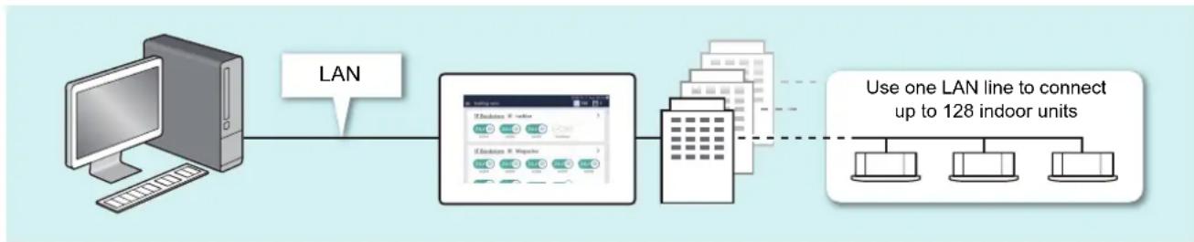
flowchart
graph LR
    A["Computer"] -->|LAN| B["Server"]
    B --> C["Client"]
    C --> D["Device"]
    D -.-> E["Device 128 Indoor Units"]
    style A fill:#f9f,stroke:#333
    style B fill:#ccf,stroke:#333
    style C fill:#cfc,stroke:#333
    style D fill:#fcc,stroke:#333
    style E fill:#cff,stroke:#333
Unit settings
1 Set the user account for remote operation (P.66)
2 Set the IP address (P.69)
3Set a destination to send email to when an alarm occurs (P.70)
PC settings
Settings
| IP address/Subnet mask | Set it to be the same network as the Unit.(For details, see the “Network Configuration Guide”.) (Example: the Unit 192.168.2.80/PC 192.168.2.90/subnet 255.255.255.0) |
| Port Release port number 8801. | |
| Drive C | Ensure that you have 500 MB or more free space and start up as a user with read/write authority. |
Operating Environment
The following environment is necessary to use this function.
| OS Windows 8.1, Windows | 10 |
| .NET Framework 4.6.2 | |
| Web browser Microsoft Edge, Internet Explorer 11, Google Chrome latest version | |
Install the software
1 Open the web browser of your PC
2 Access "http://[server name or IP address]/touchscreencontroller/[language code]/download.html"
Server name or IP address
: For the IP address, enter the value set in step 2 of "Unit settings" (P.22).
Language code : Enter the following value according to the language.
| Language Language Code | |
| Japanese | JA |
| English | EN |
| French | FR |
| German | DE |
| Italian | IT |
| Spanish | ES |
| Portuguese | PT |
| Turkish | TR |
| Polish | PL |
| Chinese | ZH |
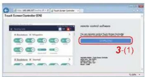
3 Click [3-(1)]
4Save the file according to the browser message
5Double-click on the saved "installer\_touchscreencontroller.exe" to unzip/install (setup.exe)
When the installation is completed, a shortcut icon is created on the desktop.

NOTE
If .NET Framework 4.6.2 is not installed on the PC, this software will not work properly.
Be sure to download and install .NET Framework 4.6.2 from the above website.
Settings when Using Report Creation Software
By using the Report Creation Software, you can easily check/output reports (monthly report/daily report) for electric power allocation summed by the Unit with a PC. When using the Report Creation Software, apply the following settings.
NOTE
For details on how to use the Report Creation Software, refer to the operation manual of the Report Creation Software.
Unit settings
1 Set the IP address of the Unit (P.69)
2 Set the summation date for the power allocation data using the Unit (P.77)
PC settings
1 Install the Report Creation Software on the PC
For details, refer to the "Installation Instructions" included in the attached DVD.
2Register the target system (this Unit) in the Report Creation Software
For details, refer to the operation manual of the Report Creation Software.
Settings when Using the PC Software Data Analyzer
When using the PC software Data Analyzer, you can display the operation status and operation history of the air conditioners aggregated by this Unit on a PC screen.
NOTE
For details on how to use the PC software Data Analyzer, refer to its operation manual.
Unit settings
1 Set the IP address of the Unit (P.69)
PC settings
1 Install the PC software Data Analyzer on the PC
For details, refer to the "Installation Instructions" included in the attached DVD.
2 Register the target system (this Unit) in the PC software Data Analyzer
For details, refer to the operation manual of the PC software Data Analyzer.
6Basic Usage
This section explains the basic setting method for operation Start/Stop and air conditioning, the setting method for the operation schedule, and the confirmation method for the overall air conditioning system.
Start/Stop Operation
Overall air conditioning system operation method
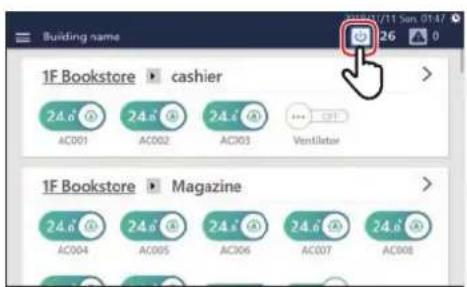
1Tap / [ICON] [ON]
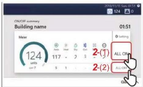
2 Tap [2-(1)] or [2-(2)]
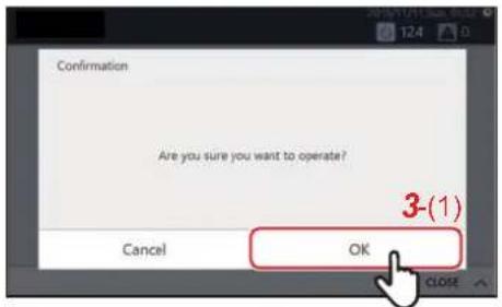
3 Check the contents of the message and tap [3-(1)]
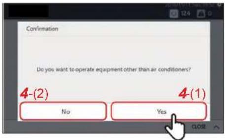
4When the screen on the left appears, check the contents of the message and tap [4-(1)] or [4-(2)] *
All air conditioners and ON/OFF unit start/stop operation.
* About confirmation pop-up selection
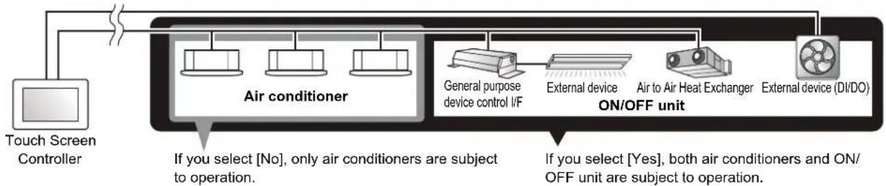
flowchart
graph LR
    A["Touch Screen Controller"] --> B["Air conditioner"]
    B --> C["General purpose device control I/F"]
    C --> D["External device"]
    D --> E["Air to Air Heat Exchanger"]
    E --> F["External device (DI/DO)"]
    B --> G["ON/OFF unit"]
    style A fill:#f9f,stroke:#333
    style B fill:#ccf,stroke:#333
    style C fill:#cfc,stroke:#333
    style D fill:#fcc,stroke:#333
    style E fill:#cff,stroke:#333
    style F fill:#ffc,stroke:#333
Group unit operation method
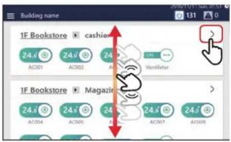
1 Scroll the home screen to display the group you want to change the settings for, then tap >
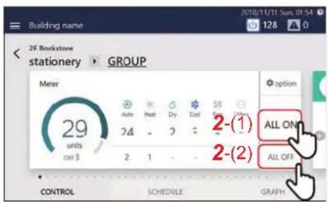
2 Tap [2-(1)] or [2-(2)]
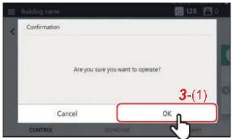
3 Check the contents of the message and tap [3-(1)]
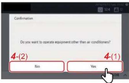
4 When the screen on the left appears, check the contents of the message and tap [4-(1)] or [4-(2)] *
All group air conditioners and ON/OFF equipment turn ON or OFF.
* About confirmation pop-up selection
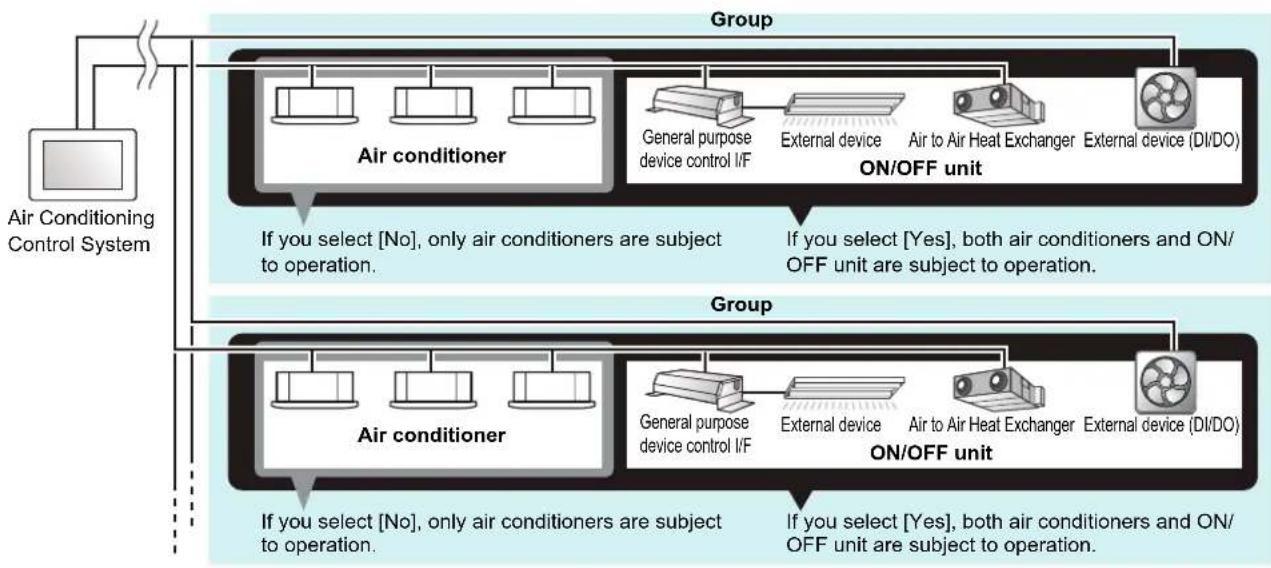
flowchart
graph TD
    A["Air Conditioning Control System"] --> B["Group"]
    B --> C1["Air conditioner"]
    B --> C2["Group"]
    C1 --> D1["General purpose device control I/F"]
    C1 --> D2["External device"]
    C2 --> D3["Air to Air Heat Exchanger"]
    C2 --> D4["External device (DI/DO)"]
    C1 --> E1["If you select [No"], only air conditioners are subject to operation.]
    C2 --> E2["If you select [Yes"], both air conditioners and ON/OFF unit are subject to operation.]
    C1 --> F1["If you select [No"], only air conditioners are subject to operation.]
    C2 --> F2["If you select [Yes"], both air conditioners and ON/OFF unit are subject to operation.]
Operation method in units of air conditioner or ON/OFF unit
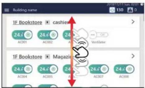
1 Scroll the home screen and display the air conditioner or ON/OFF unit that you want to change the settings for
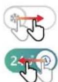

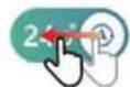

2Drag or flick the of the corresponding switch
Drag or flick to the right to start operation.
Drag or flick to the left to stop operation.
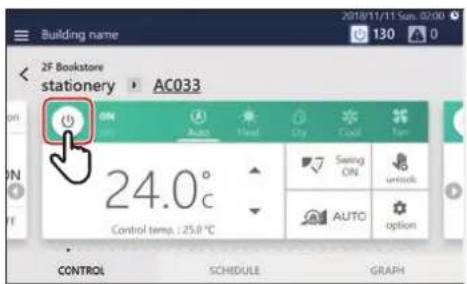
You can also start/stop operation by tapping the power icon on the [CONTROL] tab on the individual control screen displayed by tapping the switch.
NOTE
Change the Air Conditioning Settings (ON/OFF/Mode/Wind direction/Fan Speed/Set temp.)
Group unit operation method
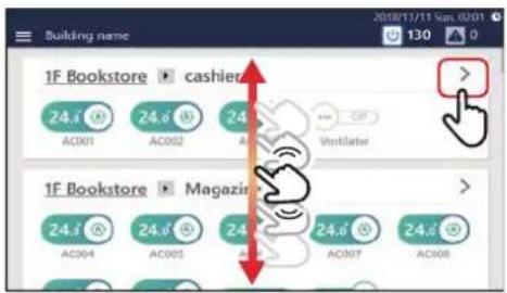
1 Scroll the home screen to display the group you want to change the settings for, then tap >
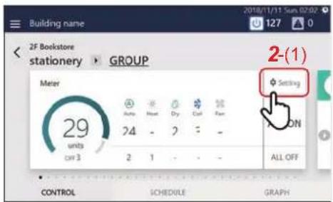
2 Tap [2-(1)]
The batch settings screen is displayed.
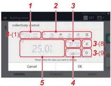
3Change settings
Example: When changing the operation status settings
3-1Tap [3-(1)]
The operation status settings screen is displayed.
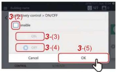
3-2 Set the check box of [3-(2)] to
You can now change the settings.
3-3 Select [3-(3)] or [3-(4)] and tap [3-(5)]
Return to the batch settings screen.
3-4 Change the other items with reference to steps 3-1 to 3-3
For the setting details, see the following table.
| No. | Name Functions | |||||||
| 1 | ON/OFF Can be set to [ON/OFF]. | |||||||
| 2 | Mode Can be set to [Auto/Heat/Dry/Cool/Fan].NOTEA bar is displayed at the bottom of the icon for the currently selected mode.Operation modes that cannot be set are not displayed. | |||||||
| No. Name Functions | ||||||||
| 3 | Wind direction Tap to switch to the following. | |||||||
 |  |  |  |  |  |  | ||
| NOTEDepending on the connected model, items that cannot be set are not displayed. | ||||||||
| 4 | Fan Speed Tap to switch to the following. | |||||||
 |  |  |  |  |  | |||
| NOTEFor models with limited fan speed setting range, this is changed to the values that can be set for each model.Fan speeds that cannot be set are not displayed. | ||||||||
| 5 | Set temp. Tap to change the set temperature. | |||||||
| NOTEWhen set to a temperature outside the setting range limit of each operation mode, the temperature is changed to the upper or lower limit of the setting range.If there are Dual Set Point compatible models in the group, two tabs will be displayed. When you tap [3-(6)], one set temperature is displayed, and when you tap [3-(7)], two set temperatures are displayed. Tap to change the set temperature.An icon and a message are displayed here during frost protection preparation, heat preparation or other operations. | ||||||||
NOTE
- For models with limited fan speed setting range, this is changed to the values that can be set for each model.
- Fan speeds that cannot be set are not displayed.
NOTE
- When set to a temperature outside the setting range limit of each operation mode, the temperature is changed to the upper or lower limit of the setting range.
- If there are Dual Set Point compatible models in the group, two tabs will be displayed. When you tap [3-(6)], one set temperature is displayed, and when you tap [3-(7)], two set temperatures are displayed. Tap to change the set temperature.
- An icon and a message are displayed here during frost protection preparation, heat preparation or other operations.
NOTE
- For models that do not have the function set, the setting change is ignored.
- For the setting of [Lock] [Unlock] of [3-(8)], see "Local Remote Controller Lock" (P.40).
- For the [Option] settings of [3-(9)], see "Set Operation Details" (P.42).
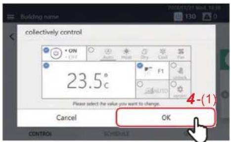
4 Confirm that the changed item is checked, and tap [4-(1)]
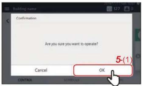
5 Check the contents of the message and tap [5-(1)]
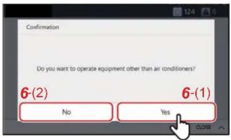
6When the screen on the left appears, check the contents of the message and tap [6-(1)] or [6-(2)] \*
The settings of the entire group are changed.
* About confirmation pop-up selection
![CARRIER BMS-CT1280UL - 6When the screen on the left appears, check the contents of the message and tap [6-(1)] or [6-(2)] \* - 1](/content/2026/05/959133/images/0da6f237efbb9108a1c78c5bd8165a858126766aba4b83537b7cb10081693826.jpg)
flowchart
graph TD
    A["Air Conditioning Control System"] --> B["Group"]
    B --> C1["Air conditioner"]
    B --> C2["General purpose device control I/F"]
    B --> C3["Air to Air Heat ExchangerExternal device External device"]
    C1 --> D1["Group"]
    C2 --> D1
    C3 --> D1
    D1 --> E1["If you select [No"], only air conditioners are subject to operation.]
    D1 --> E2["If you select [Yes"], both air conditioners and ON/OFF unit are subject to operation.]
    D2 --> F1["Group"]
    D2 --> F2["Air conditioner"]
    D2 --> F3["General purpose device control I/F"]
    D2 --> F4["Air to Air Heat ExchangerExternal device External device"]
    F1 --> G1["Group"]
    F2 --> G1
    F3 --> G1
    F4 --> G2["Group"]
    F4 --> G2
    G1 --> H1["Group"]
    G1 --> H2["Group"]
    G2 --> H2
Air conditioner unit operation method
NOTE
To change the settings, it is necessary to set to the operation status. (P.27)
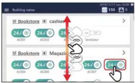
1 Scroll the home screen, display the air conditioner you want to change the settings for, then tap the switch
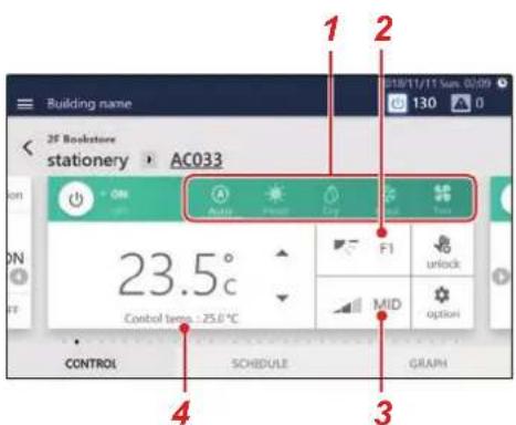
2Change settings
| No. Name Functions | ||||||||||
| 1 | Mode Can be set to [Auto/Heat/Dry/Cool/Fan].NOTEA bar is displayed at the bottom of the icon for the currently selected mode.Operation modes that cannot be set are not displayed. | |||||||||
| 2 | Wind direction Tap to switch to the following.    [WSZD] [WSZD]   | |||||||||
| No. Name Functions | |||||||
| 3 | Fan Speed Tap to switch to the following. | ||||||
NOTE
- For the setting of [(1)], see "Local Remote Controller Lock" (P.40).
- For the setting of [(2)], see "Set Operation Details" (P.42).
- If there is no corresponding function, that item is not displayed.
Example of a model without a flap
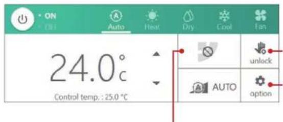
Since you cannot set the air direction, it does not change even if you tap it.
Example of a model where only a certain fan speed can be set
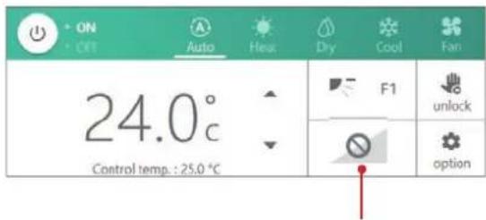
Since you cannot change the fan speed, it does not change even if you tap it.
Set the Operation Schedule
You can configure the air conditioners or the ON/OFF unit with a "Week Schedule", through which settings such as operation start/stop are changed depending on the specified time for any day from Sunday to Saturday, or a "Particular Timer setting", through which settings are changed for special days such as national holidays or special holidays. The operation schedule is set on the [SCHEDULE] tab of the group screen or individual control screen.
NOTE
If a day is set in both the Week Schedule and the Particular Timer setting, the Particular Timer setting applies and the Week Schedule is disabled for that day.
Screen description
This section explains how to view the [SCHEDULE] tab when setting the operation schedule.
NOTE
Refer to the description of the [CONTROL] tab for the display items that are not explained. (P.16, 18)
Group screen
The schedule set for the air conditioners or ON/OFF unit in the group is displayed in list format in time units.
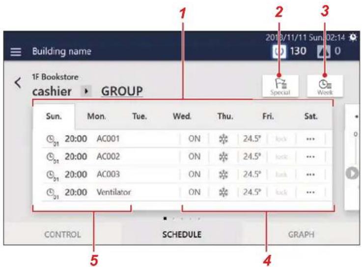
| No. Functions | |
| 1 | You can switch the display in day-of-week units. |
| 2 | Displays the setting screen of Particular Timer setting. |
| 3 | Displays the setting screen of Week Schedule. |
| 4 | The schedule settings content (ON/OFF, Mode, Temp., Lock, more) is displayed. |
| 5 | The times when the schedule is executed and the air conditioners and ON/OFF unit for which the schedule is executed are displayed. |
Individual control screen
The schedule set for the air conditioner or ON/OFF unit being displayed is displayed on a 24-hour time scale.
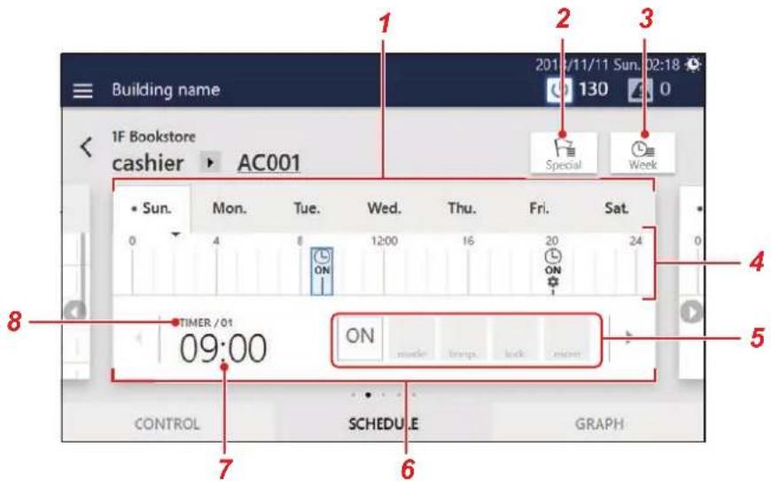
| No. Functions | |
| 1 | You can switch the display in day-of-week units. |
| 2 | Displays the setting screen of Particular Timer setting. |
| 3 | Displays the setting screen of Week Schedule. |
| 4 | is displayed at the times when the schedule is set.When operation start/stop is set, [ON] or [OFF] is displayed below . When setting change is set, is displayed below . Also, the currently displayed schedule is displayed in blue. |
| 5 | The schedule settings content (ON/OFF, Mode, Temp., Lock, more) is displayed. |
| 6 | You can switch the display to the previous or next schedule. |
| 7 | The times when the schedule will be executed are displayed. |
| 8 | The schedule setting number is displayed. |
Create a new Week Schedule
In a Week Schedule, you can set:
- Start time
• Day(s) of the week
• Air conditioner(s) or ON/OFF unit - ON/OFF
Schedule settings can be applied from either the group screen or the individual control screen. In the following procedure, the individual control screen is used to explain.
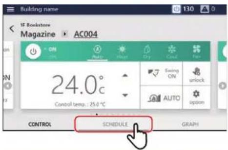
1 Tap [SCHEDULE] on the group screen or individual control screen
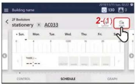
2 Tap [2-(1)]
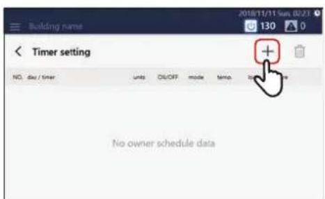
3Tap
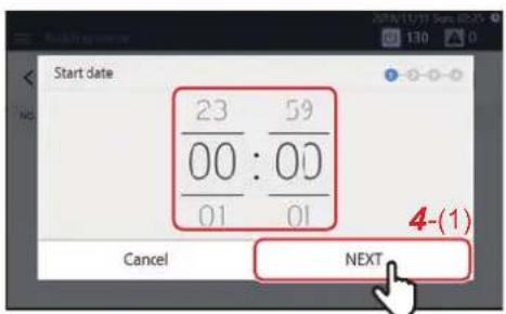
4 Tap or flick to set the start time and tap [4-(1)]
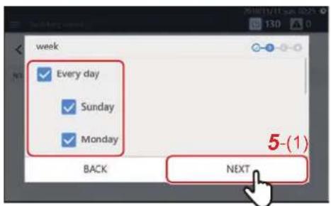
5 Select the day of the week to execute and tap [5-(1)]
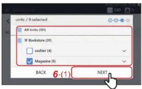
6 Select the air conditioner(s) or ON/OFF unit for setting the schedule and tap [6-(1)]
You cannot select a model that has already been scheduled at the same time.
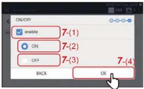
7 Tap the check box of [7-(1)] and set it to √, then select [7-(2)] or [7-(3)] and tap [7-(4)]
You can only set [ON/OFF] here.
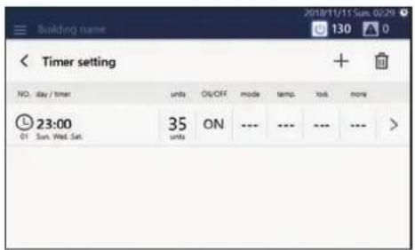
A schedule has been registered.
NOTE
- When setting details such as operation mode or set temperature, etc. as a schedule, refer to "Change the Operating Schedule" (P.48).
- When deleting a registered schedule, refer to "Delete the operation schedule" (P.54).
Create a new Particular Timer setting
In a Particular Timer setting, you can register special days, such as national holidays and special holidays, to configure a special schedule that differs from the Week Schedule.
Schedules can be configured from the group screen or the individual control screen. The following procedure is explained using the individual control screen.
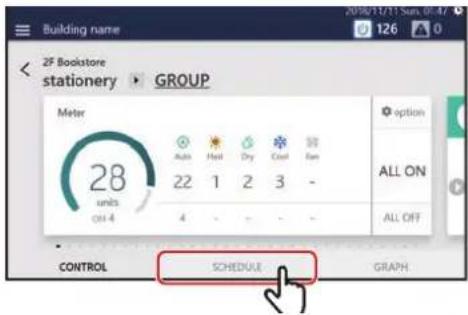
1 Tap [SCHEDULE] on the group screen or the individual control screen
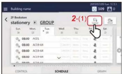
2 Tap [2-(1)]
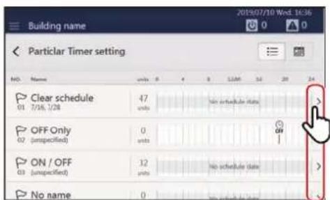
3Tap >
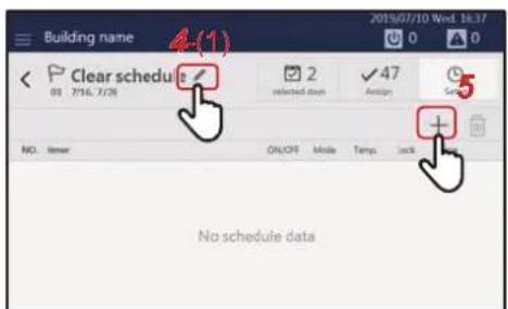
4 Tap [4-(1)] and set the schedule name A keyboard is displayed. Enter the name and then tap [4-(2)].
![1 2 3 4 5 6 7 8 9 0 - - q w e r t y u i e p [ ] a s d f g h j k l Shift z x c v b n m / Shift > Cancel OK](/content/2026/05/959133/images/968360da150a505ad654e8524131eedf3eee0cf335d03e2c75b6654dd43900c5.jpg)
5Tap to go to step 6
NOTE
- Tap [Shift] to toggle between upper case letters and lower case letters, and numbers and symbols.
- Tap to delete one character.
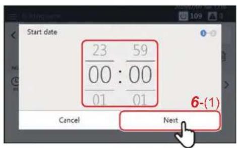
6 Tap or flick to set the start date, and then tap [6-(1)]
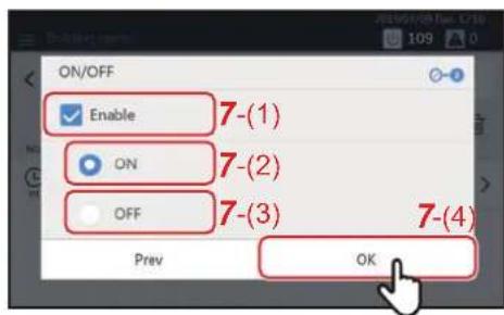
7 Tap the check box of [7-(1)] and set it to √, then select [7-(2)] or [7-(3)] and tap [7-(4)]
You can only set [ON/OFF] here.
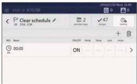
The schedule is registered.
NOTE
- When setting details such as the mode or the set temperature to a schedule, refer to "Change the details of the Particular Timer setting" (P.50).
- When deleting a registered schedule, refer to "Delete the operation schedule" (P.54).
Monitor the Overall Air Conditioning System
To check the operation status of the overall air conditioning system, tap 📄/💡 to display the batch ON/OFF screen. To check the alarm occurrence status, tap 📄 to display the alarm history screen.
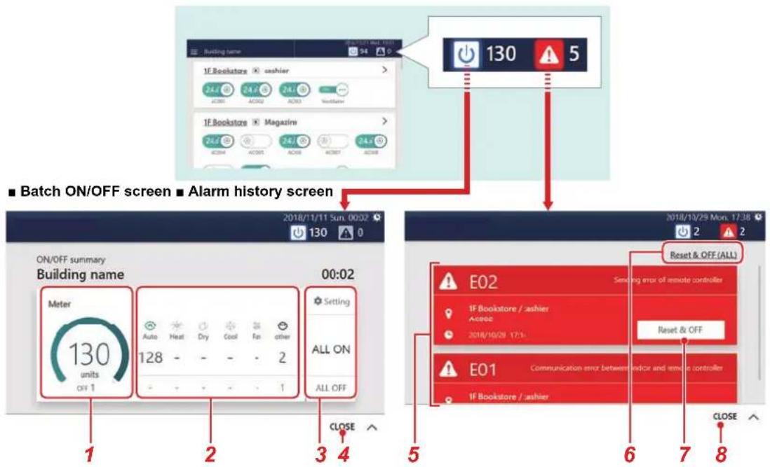
| No. Functions | |
| 1 | Displays the overall number of operating units as ON/OFF meters and numerical values. |
| 2 | Displays the number of units for each operation mode. The upper row shows the number of units in operation and the lower row shows the number of units stopped.If there is ON/OFF unit, it is displayed in [Other]. |
| 3 | You can change the operation status of the overall air conditioning system. (P.25)For the Option settings, see step 3 on (P.28). |
| 4 | Tap to close the batch ON/OFF screen.NOTEYou can also tap to close. |
| 5 | The alarm code, alarm content, occurrence location, and occurrence time are displayed. |
| 6 | Stop operation of all air conditioners and ON/OFF unit where alarms have occurred and erase the alarm(s).NOTEFor some ON/OFF unit, only the operation stops, and the alarm(s) are not erased. |
| 7 | Stop the applicable air conditioner(s) or ON/OFF unit and erase the alarm(s).NOTEFor some ON/OFF unit, only the operation stops, and the alarm(s) are not erased. |
| 8 | Tap to close the alarm history screen.NOTEYou can also tap to close. |
7Various Functions
This section explains detailed settings on the [CONTROL] tab, how to change the schedule on the [SCHEDULE] tab, and how to check the power usage on the [GRAPH] tab.
Local Remote Controller Lock
You can restrict operation of the local remote controllers that belong to each air conditioner.
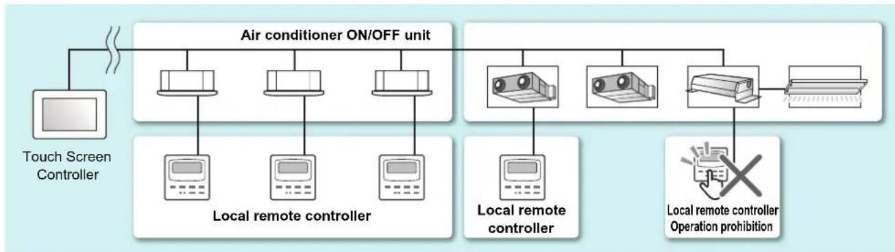
flowchart
graph TD
    A["Touch Screen Controller"] --> B["Air conditioner ON/OFF unit"]
    B --> C["Local remote controller"]
    B --> D["Local remote controller"]
    B --> E["Local remote controller"]
    B --> F["Local remote controller"]
    B --> G["Local remote controller Operation prohibition"]
    C --> H["Computer"]
    D --> I["Computer"]
    E --> J["Computer"]
    F --> K["Computer"]
    G --> L["Computer"]
1 Display the [CONTROL] tab of the air conditioner(s) whose setting you want to change (P.16,18) When changing in group units, display the batch settings screen (P.28)
In the following procedure, the [CONTROL] tab of the individual control screen is used to explain.
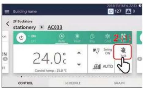
2 Tap [2-(1)]

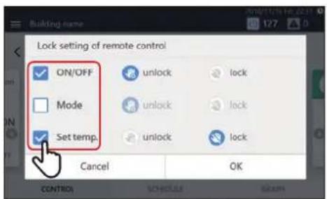
3Tap the check box of the function whose setting you want to change to set it to √
| NOTE |
| The display items vary depending on the model. |
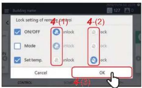
4 Select [4-(1)] or [4-(2)], then tap [4-(3)]
![•REQUIREMENT If you set the check box to □ before tapping [4-(3)], the setting will not be applied.](/content/2026/05/959133/images/6bc0b8dec7594a5b1c62336f70e9dcb6ea86911a16c339b4aa6165168adeaae5.jpg)
NOTE
When local remote control operation is prohibited, if there is a power failure, the local remote control prohibited status will be cancelled when the power returns.
Ask service personnel if you want to continue the local remote control prohibited status after returning from a power failure.
NOTE
If you perform an operation that is locked with the local remote controller, the lock screen or a message will be displayed.
Lock screen example
(Energy saving neo remote controller)
(Wired remote controller)
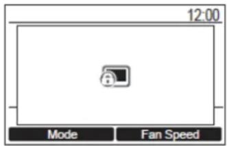
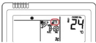
Set Operation Details
You can check the current settings of the air conditioner(s) or ON/OFF unit, and set the details of the operation method.
1 Display the [CONTROL] tab of the air conditioner(s) or ON/OFF unit whose setting you want to change (P.18)
When changing in group units, display the batch settings screen (P.28)
In the following procedure, the individual control screen is used to explain.
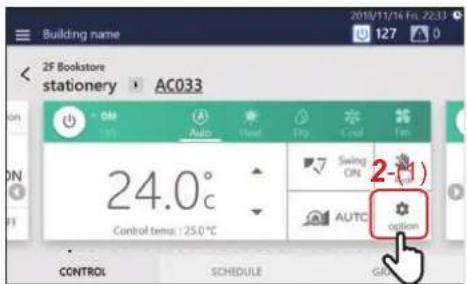
2 Tap [2-(1)]
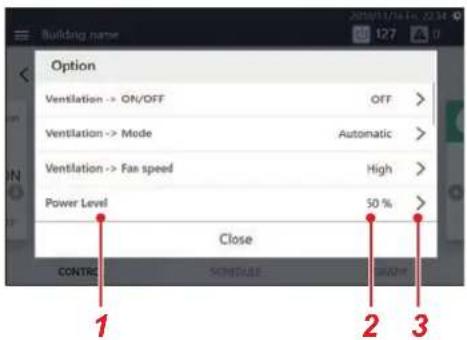
The option screen appears.
| No. Functions | |
| 1 | The function name appears. |
| 2 | The currently set contents are displayed. If the settings are invalid, "-" is displayed. |
| 3 | When the settings can be changed, is displayed. Tap to display the settings screen. |
3 Scroll up and down to display the items you want to set/check
4 To change, tap > to display the settings screen, then tap [OK] after changing the settings For details on the confirmation/setting contents of each item, refer to the following. The items displayed depend on the model and state.
| Function Name Overview Setting Items | Reference Page | ||
| Ventilation → ON/OFF | Controls the operation of the ventilator connected to the air to air heat exchanger(s) or the air conditioner(s). | ON/OFF P.44 | |
| Ventilation → Mode | Controls the ventilation mode of the ventilator connected to the air to air heat exchanger(s) or the air conditioner(s). | Bypass/Heat exchange/Automatic | P.44 |
| Ventilation → Fan speed | Controls the operation of the ventilator connected to the air to air heat exchanger(s) or the air conditioner(s). | High/Middle/Supply air > Exhaust air/Exhaust air > Supply air | P.44 |
| Ventilation → Control | 24-hour ventilation/Nighttime heat purge | - | - |
| Power Level | You can monitor the output status of the air conditioner(s). | - | P.45 |
| Outdoor temp. | You can monitor the temperature inside the room detected by the outdoor unit. | - | P.45 |
| Filter sign reset | You can clear the FILTER Sign.You can clear the Hour. | OK/Cancel | P.45 |
| Soft Cooling | You can set to Middle COOL. | ON/OFF | P.45 |
| Energy saving ratio [%] | You can control the cooling/heating output of the air conditioner(s). | Release/Max./50/0 | P.46 |
| Forced Thermo OFF | You can release Thermo OFF. | Invalid | P.46 |
| Return Back You can monitor Return Back.Return Back is set by the operation schedule. | - | P.46 | |
| Power peak cut | You can monitor whether the outdoor unit is controlling demand. | - | P.46 |
| Eco Temperature Shift | You can set whether to change (shift) the set temperature. | Shift the set temperature to the energy saving temperature | P.47 |
| Set temp. range limit | You can change the set temperature range for each operation mode. | 64°F to 84°F* It may differ depending on the region and model. | P.47 |
Turn ON/OFF the ventilation function (Ventilation → ON/OFF)
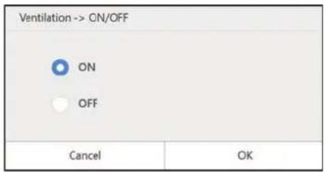
You can turn ON/OFF the operation of the ventilator connected to the air to air heat exchanger(s) or air conditioner(s).
NOTE
Displayed when a configurable model is connected.
Set Ventilation Mode (Ventilation → Mode)
You can set the ventilation mode of the ventilator connected to the air to air heat exchanger(s) or the air conditioner(s). The settings screen displayed differs depending on the setting state of [Ventilation → ON/OFF].
◆When [ON] is selected under [Ventilation → ON/OFF]
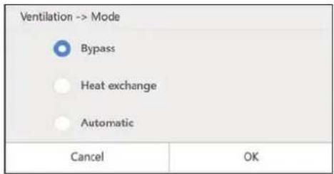
Bypass: Outdoor air is taken into a room as it is. We recommend using this mode in the middle of spring and autumn. Heat exchange: Exchanging heat between the outdoor air and return air and making the temperature and humidity of the outdoor air closer to those of the return air before supplying it. We recommend you use this mode for cooling and heating in summer and winter. Automatic: Total Heat Ventilation and Bypass Ventilation are switched automatically.
NOTE
- Depending on the connected model, items that cannot be set are not displayed.
- Some items may not be configurable.
Setting the ventilation fan speed (Ventilation → Fan speed)
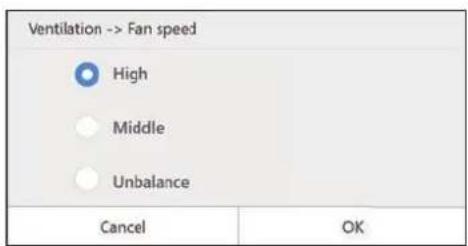
You can set the ventilation fan speed of the ventilator connected to the air to air heat exchange unit or the air conditioner. The choices displayed depend on the model.
NOTE
- Displayed when a configurable model is connected.
- It is displayed when [Ventilation → ON/OFF] is [ON] and setting change is possible.
* Imbalance between ventilation and exhaust varies depending on the settings of the connected model.
Check the output status of the air conditioner(s) (Power Level)
| Option | ||
| Ventilation -> Mode | Bypass | > |
| Ventilation -> Fan speed | High | > |
| Power Level | 50 % | > |
| Outdoor temperature | 26.0 °C | > |
| Close | ||
You can check how much power the air conditioner is using for operation.
NOTE
Displayed in the case of a compatible air conditioner.
Check the indoor temperature detected by the outdoor unit (Outdoor temp.)
| Option | ||
| Ventilation -> Mode | Bypass | > |
| Ventilation -> Fan speed | High | > |
| Power Level | 50 % | > |
| Outdoor temperature | 26.0°C | > |
| Close | ||
You can check the temperature inside the room detected by the outdoor unit.
NOTE
- Displayed in the case of a compatible air conditioner.
- Depending on conditions such as the location of the indoor unit installation, it may differ from the actual indoor temperature.
Erase FILTER Sign (Filter sign reset)
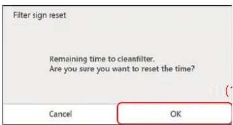
When a device has operated for a certain period of time, a warning (FILTER Sign) is displayed to indicate that the filter should be cleaned. After filter cleaning, tap [(1)].
NOTE
- Displayed in the case of a compatible air conditioner.
- If you set the air conditioners where a sign is displayed to [OK], the cumulative time for the sign display is set to 0.
Set Middle COOL (Soft Cooling)
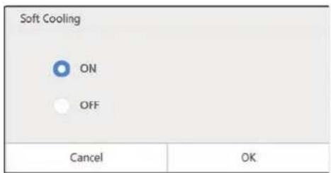
Middle COOL can be turned ON/OFF. When turned ON, the air direction is set to up, and the maximum power is restricted.
NOTE
- Displayed when a configurable model is connected.
- The settings screen is displayed when the air conditioner is in operation and the operation mode is COOL.
Control air conditioner power (Energy saving ratio [%])
An energy saving function whereby you can operate the air conditioner with suppressed cooling/heating power.
Release: Save Mode is not performed.
Max.: Operate with the highest save rate.
50: Operate at 50% save rate.
0: Operate at 0% cooling/heating power (Thermo OFF).
NOTE
The settings screen is displayed when a compatible air conditioner is in operation.
Release Thermo OFF (Forced Thermo OFF)
"Thermo OFF" refers to an energy saving function that controls demand to restrict the cooling/heating power of the air conditioner such that the outdoor unit compressor is stopped. When this state is reached, the air conditioner becomes a fan and cold/hot air is no longer output.
To release Thermo OFF, display the settings screen and press [OK].
NOTE
Displayed in the case of a compatible air conditioner.
Configure and confirm the Return Back settings (Return Back)
You can configure and check the Return Back setting temperature and setting time of each operation mode that are set in the operating schedule.
NOTE
- Displayed in the case of a compatible air conditioner.
- For information on Return Back, see "Return Back settings" (P.53).
Monitor demand control of outdoor unit (Power peak cut)
You can monitor the demand rate [%], outdoor line No., and schedule No. of the outdoor unit connected to the selected air conditioner.
Display the settings screen to check the demand status of the outdoor unit.
NOTE
Displayed in the case of a compatible air conditioner.
Change to energy saving temperature (Eco Temperature Shift)
An energy saving function that changes (shifts) the set temperature according to the current operation mode as follows.
| Operation Mode Set Temperature Shift Width | |
| Cool/Dry Current set temperature +2°C shift (About +4°F) | |
| Heat Current set temperature -2°C shift (About -4°F) | |
| Auto/Fan Remain at current set temperature |
NOTE
- Displayed in the case of a compatible air conditioner.
- When the Mode is set to [Heat], [Cool], or [Dry], the settings screen is displayed.
Set the temperature change range (Set temp. range limit)
You can set the set temperature range for each operation mode.
NOTE
- Displayed in the case of an air conditioner. It is not displayed in the case of ON/OFF unit.
- If the current set temperature of the air conditioner is outside of the set temperature range after the change, it will be changed to the temperature within the range after the change.
![Set temp. range limit Cool [°C] 18 ~ 29 Heat [°C] 18 ~ 29 Dry [°C] 18 ~ 29 Auto [°C] 18 ~ 29 Cancel OK](/content/2026/05/959133/images/e9dd82afbcff13a1519c8e937e42bed450288ae6d3474a4d1683e27e64dee739.jpg)
1 Tap the upper/lower limit temperature you want to change
NOTE
- Displayed in the case of a compatible air conditioner.
- Some operation modes are not displayed depending on the model.
![Cool Maximum -- [°C] 0 1 2 3 4 5 6 7 8 9 Cancel 2-(1) OK](/content/2026/05/959133/images/8d87d84df92dbb7a802e27e4c7975b466328582c6fdf296103df4e8925bc13de.jpg)
2 Tap the number, enter the temperature, and tap [2-(1)]
Change the Operating Schedule
The operating schedule settings can be changed from the [Menu] button, the group screen, or the individual control screen. There are two types of operating schedules: Week Schedule and Particular Timer setting.
The following procedure is explained using the individual control screen.
NOTE
If a day is set in both the Week Schedule and the Particular Timer setting, the Particular Timer setting applies and the Week Schedule is disabled for that day.
Change the details of the Week Schedule
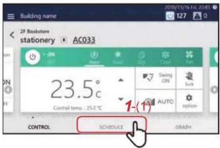
1 Tap [1-(1)] on the group screen or the individual control screen
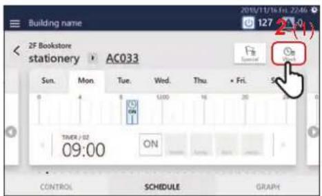
2 Tap [2-(1)]
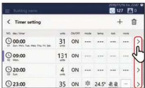
3Tap of the schedule you want to modify
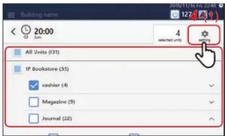
4 Modify the target air conditioner(s) or ON/OFF unit, then tap [4-(1)]
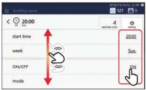
5 Scroll the screen and tap the value of the item you want to set. After changing the setting, tap [OK]
See "Setting items list" (P.52) for the items that can be configured.
Change the details of the Particular Timer setting
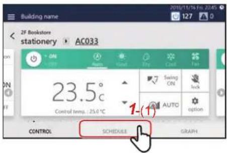
1 Tap [1-(1)] on the group screen or the individual control screen
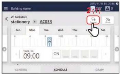
2 Tap [2-(1)]
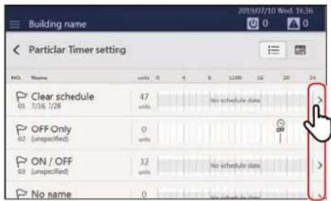
3Tap of the schedule you want to modify
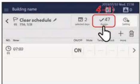
4 Tap [4-(1)] to switch to the Assign screen
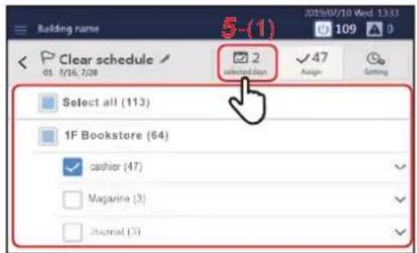
5 Modify the target air conditioner(s) or ON/OFF unit, then tap [5-(1)]
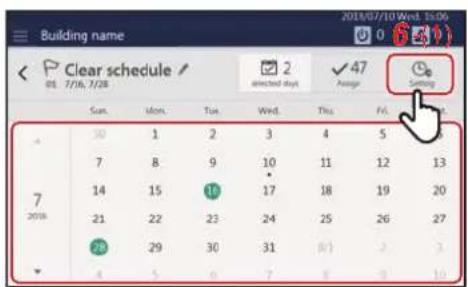
6 Tap the date you want to configure, modify the settings, and then tap [6-(1)]
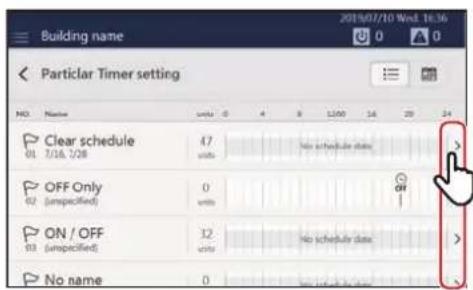
7 Tap of the schedule you want to modify
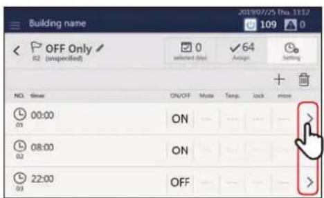
8Tap of the time you want to modify
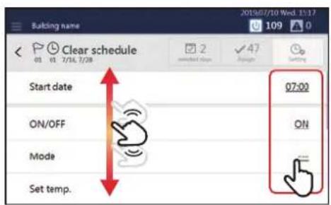
9 Scroll the screen and tap the value of the item you want to set. After changing the setting, tap [OK]
See "Setting items list" (P.52) for the items that can be configured.
Setting items list
| Setting Items Setting Procedure | |
| Time setting [Start date] | Tap or flick to change the time. |
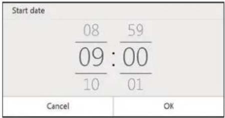 | |
| Day of the week setting [week] | Set the check box(es) of the day(s) of the week on which you want to execute the schedule to √.NOTE |
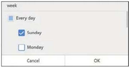 | The day of the [week] setting is not displayed in Particular Timer setting. |
| Operation setting [ON/OFF] | To enable the setting, set the check box of [(1)] to and select a value. |
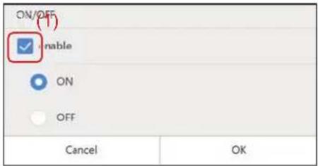 | |
| Operation mode setting [Mode] | To enable the setting, set the check box of [(2)] to and select a value. |
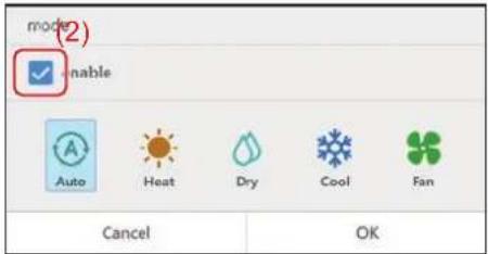 | |
| Set temperature setting [Set temp.] | To enable the setting, set the check box of [(3)] to , tap , then change the set temperature. |
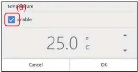 | |
Return Back settings [Return Back]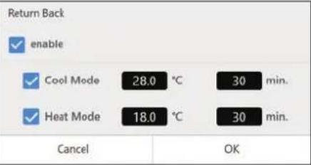 | An energy saving function whereby if you temporarily change the set temperature to one which increases the load, you can automatically return to the energy saving set temperature after a certain time has elapsed. For example, if you set COOL to 82°F/30 minutes, then if the set temperature is set to below 82°F, the Unit will return to 82°F 30 minutes after the change.NOTEDisplayed in the case of a compatible air conditioner. |
Local operation prohibition setting [Lock setting of remote control]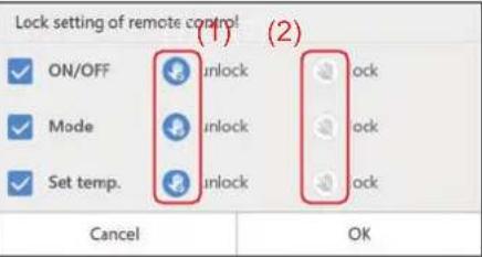 | Tap the check box of the function whose setting you want to change to set it to .then select [(1)] or [(2)]. |
Save operation setting [Energy saving ratio[%]]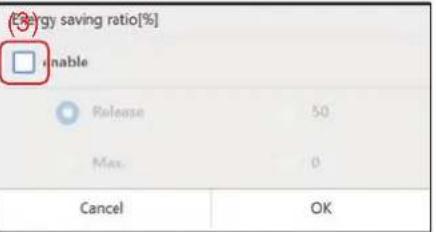 | To enable the setting, set the check box of [(3)] to .For details, see "Control air conditioner power (Energy saving ratio [%])" (P.46)". |
Ventilation operation setting [Ventilation -> ON/OFF]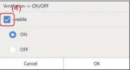 | You can turn ON/OFF the operation of the ventilator connected to the air to air heat exchanger(s) or air conditioner(s). To enable the setting, set the check box of [(4)] to and apply the setting. |
Vent. Mode [Ventilation -> Mode]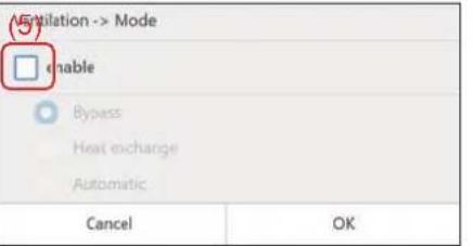 | You can set the ventilation mode of the ventilator connected to the air to air heat exchanger(s) or the air conditioner(s).To enable the setting, set the check box of [(5)] to and apply the setting. For details, see "Set Ventilation Mode (Ventilation → Mode)" (P.44). |
Delete the operation schedule
You can delete the schedule from either the group screen or the individual control screen. In the following procedure, the individual control screen is used.
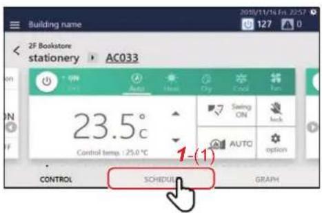
1 Tap [1-(1)] on the group screen or individual control screen
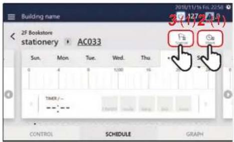
2 Tap [2-(1)] to go to step 4
3 (In case of Particular Timer setting) tap [3-(1)]
Tap > of the schedule you want to modify to go to step 4.
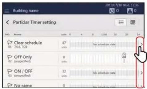
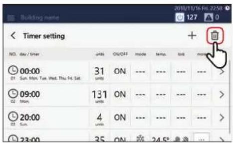
4Tap

(Some displayed items differ between the Week Schedule screen and the Particular Timer setting screen, but the procedure shown below is the same.)
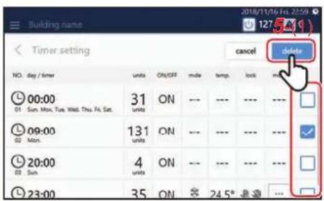
5Set the check box of the schedule you want to delete to then tap [5-(1)]

Confirm the Operation Time
In the [GRAPH] tab of the group screen or individual control screen, you can check the operation time for each group, air conditioner or ON/OFF unit. You can find the peak period of operation and waste operation.
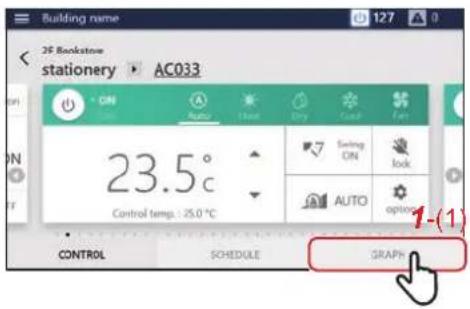
1 Tap [1-(1)] on the group screen or individual control screen
The operation graph appears.
Group screen Individual control screen
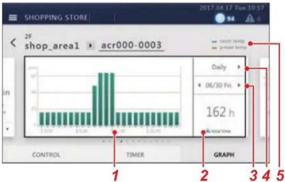
bar
| Time (h) | Volume | |---|---| | 0 | 15 | | 1 | 15 | | 2 | 15 | | 3 | 15 | | 4 | 15 | | 5 | 15 | | 6 | 15 | | 7 | 15 | | 8 | 15 | | 9 | 15 | | 10 | 15 | | 11 | 15 | | 12 | 15 | | 13 | 15 | | 14 | 15 | | 15 | 15 | | 16 | 15 | | 17 | 15 | | 18 | 15 | | 19 | 15 | | 20 | 15 | | 21 | 15 | | 22 | 15 | | 23 | 15 | | 24 | 15 | | 25 | 15 | | 26 | 15 | | 27 | 15 | | 28 | 15 | | 29 | 15 | | 30 | 15 | | 31 | 15 | | 32 | 15 | | 33 | 15 | | 34 | 15 | | 35 | 15 | | 36 | 15 | | 37 | 15 | | 38 | 15 | | 39 | 15 | | 40 | 15 | | 41 | 15 | | 42 | 15 | | 43 | 15 | | 44 | 15 | | 45 | 15 | | 46 | 15 | | 47 | 15 | | 48 | 15 | | 49 | 15 | | 50 | 15 | | Control | - | | TIMER | - | | GRAPH | - | | Daily | - | | 06/30 Fri. | - | | 162 h | - |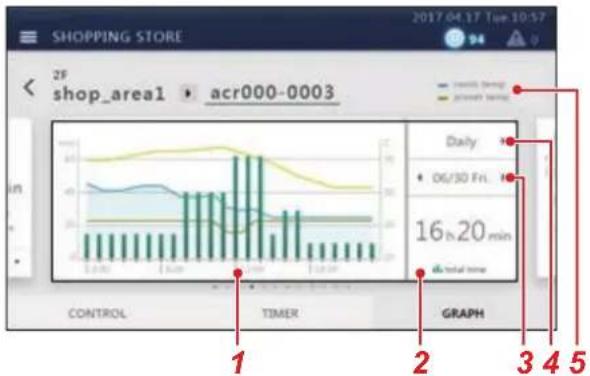
bar_line
| Time | Daily Volume (units) | | :--- | :--- | | 06/30 Fri. | 16 h 20 min | | Total time | 16 h 20 min || No. Functions | |
| 1 | The hourly or daily operation hours are shown as a bar graph.For the individual control screen, the outdoor temperature, room temperature, and set temperature are displayed as a line graph. |
| 2 | The operation hours for the displayed summary period is displayed. |
| 3 | Displays the currently displayed date. Tap to switch the date.Tap the centre to select the display period from the calendar screen.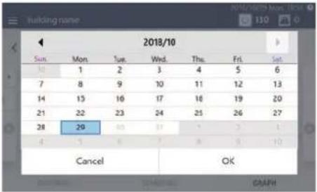 |
| 4 | You can change the summary unit to day or month. |
| 5 | The legend for the graph appears. |
NOTE
Refer to the description of the [CONTROL] tab for other displays. (P.16, 18)
8Administrator menu
Restrict Operation of the Touch Screen Controller (Operation Lock)
You can restrict the operation range of the Unit by locking it.
This section explains how to set and release the lock.
For the restriction range, see "Set the operation lock level (Operation lock)" (P.68).
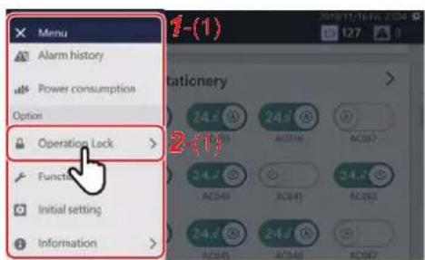
1Tap
[1-(1)] appears.
2 Tap [2-(1)]
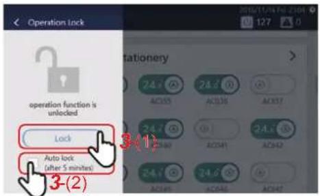
Below, the screen for release is explained.
3 Tap [3-(1)]
To change the auto lock settings, tap [3-(2)]
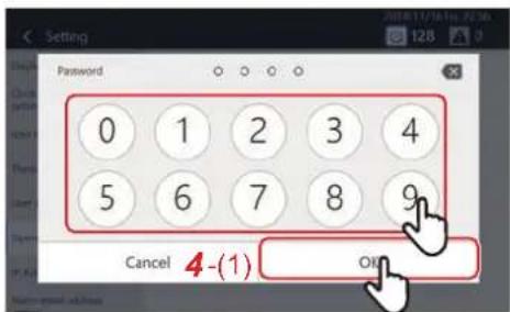
4 Tap the number, enter the 4-digit password, then tap [4-(1)]
The lock is set or released.
NOTE
• The initial set password is "1048".
• There are two levels of protection when locking. (P.68)
- Tap to delete one character.
NOTE
- You can change the password. (P.68) If you do not know the password, please contact your administrator.
- If you enter the wrong password three times when unlocking, password input is restricted for 30 minutes.
- When automatic lock is set, the Unit will be locked automatically after 5 minutes have passed after an operation has completed.
- When the lock is set, if you tap a function that cannot be operated, the message "operation function is locked" is displayed. Also, appears in the menu.
Confirm Alarm History (Alarm history)
You can display alarms that have occurred in a list, including currently occurring alarms. This can be used for grasping the status of the site such as investigating the cause of an alarm and the recovery status.
NOTE
The past 1000 alarms are displayed.
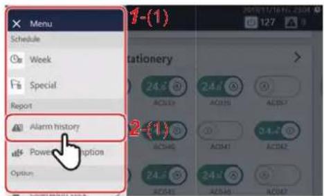
1Tap

[1-(1)] appears.
2 Tap [2-(1)]
3The alarm history screen appears
The detected alarms are listed in chronological order.
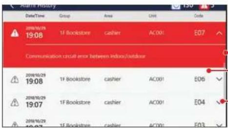
Currently occurring alarms are displayed with a red background.
Past alarms are displayed with a white background.
Tap to display the details of the alarm contents.
Confirm the Power consumption on a Graph (Power consumption)
Pulse values are graphed and the electric power can be visually confirmed.
* This function can be displayed when the electric power is measured by connecting this Unit to a pulse oscillation type watt hour meter.
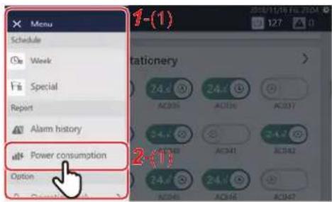
1Tap

[1-(1)] appears.
2
Tap [2-(1)]
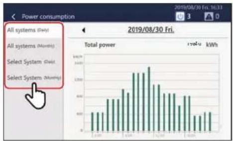
bar
| System | Power consumption (kWh) | | :--- | :--- | | All systems (Over) | 100 | | All systems (Monthly) | 120 | | Select System (Over) | 150 | | Select System (Monthly) | 130 |3
ap the data type to be displayed
All systems (Daily):
You can display the total electric power on a daily basis on a graph.
All systems (Monthly):
You can display the total electric power on a monthly basis on a graph.
Select System (Daily):
You can select the watt hour meter to sum and display the daily electric power on a graph.
Select System (Monthly):
You can select the watt hour meter to sum and display the monthly electric power on a graph.
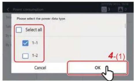
4
to select [Select System(Daily)] or [Select System(Monthly)], set the check box of the watt hour meter to sum to and tap [ 4-(1)]
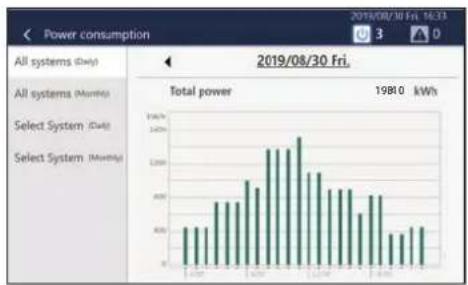
bar
| System | Power Consumption (kWh) | | :--- | :--- | | All systems (Day) | 450 | | All systems (Month) | 460 | | Select System (Day) | 500 | | Select System (Month) | 520 | | Total power | 19810 kWh |An electric power graph is displayed.
NOTE
Tap to change the summary period to display. You can also tap the displayed date to display the calendar and change the summary period.
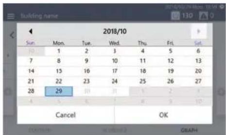
[Functions] Menu Settings
On the [Functions] menu, demand control of outdoor units and summation of data for power allocation can be performed.
How to display the [Functions] menu
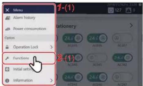
1Tap
[1-(1)] appears.
2 Tap [2-(1)]
[3-(1)] appears.
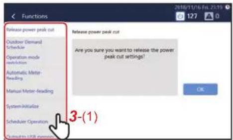
3 Tap the item you want to set with [3-(1)]
The settings screen of the selected item appears on the right.
For details on the setting contents of each item, refer to the following.
- Release power peak cut (P.59)
• Power peak cut schedule (P.60)
• Operation mode restriction (P.62)
• Automatic Meter-Reading (P.77)
• Manual Meter-Reading (P.78) - System reboot (P.62)
• Scheduler Operation (P.63)
• Output to USB memory (P.63)
Release demand control of outdoor unit (Release power peak cut)
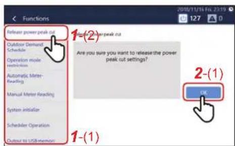
1 Tap [1-(2)] with [1-(1)]
2 Tap [2-(1)]
Outdoor demand set for all outdoor units is released.
NOTE
- Outdoor demand can be set by the "Power peak cut schedule". (P.60) Outdoor demand may function with digital input set locally. In this case it can also be released.
- When you release the Power peak cut, the setting value of [Power peak cut] on the option screen changes to the release state. (P.46)
Set demand control schedule of outdoor unit (Power peak cut schedule)
The demand function of the outdoor unit can be managed with the schedule to 90 to 0% according to the peak time zone.
Setting example:
When "80%" at midnight on Monday, "90%" at midnight on Saturday, and "Release" at midnight on Sunday is set:
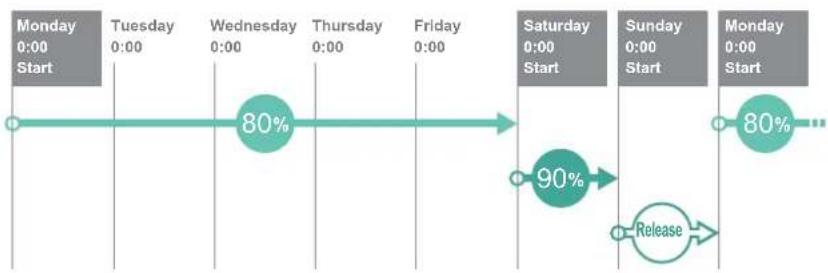
flowchart
graph LR
    A["Monday 0:00 Start"] --> B["Tuesday 0:00"]
    B --> C["Wednesday 0:00"]
    C --> D["Thursday 0:00"]
    D --> E["Friday 0:00"]
    E --> F["Saturday 0:00 Start"]
    F --> G["Sunday 0:00 Start"]
    G --> H["Monday 0:00 Start"]
    H --> I["Release"]
    I --> J["90%"]
    J --> F
NOTE
- Cannot be set when the Outdoor Demand Schedule is disabled. Please enable the Outdoor Demand Schedule. (P.63)
- Demand levels that can be set are "Release", "90%", "80%", "70%", "60%" and "0%".
- Up to 10 schedules can be created.
Add/change Power peak cut schedule
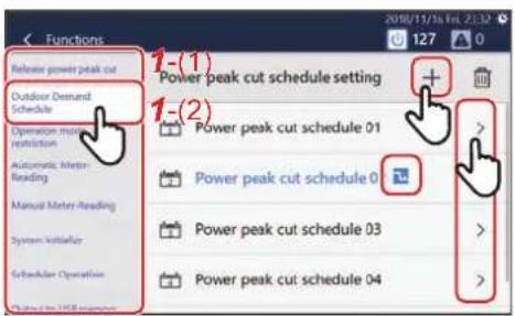
1 Tap [1-(2)] with [1-(1)] (P.59)
2Tap to register new
To change, tap of the schedule you want to change
NOTE
When the demand function is functioning at the current time, appears.
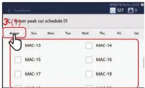
3 Tap [3-(1)] and set the check box of the outdoor unit for setting the Power peak cut schedule to √
NOTE
The schedule number ( ) will be displayed on outdoor units that have already been scheduled. Cannot be selected.
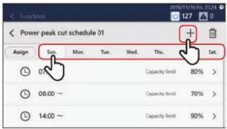
4 Tap the day of the week tab to start the schedule, then tap + To change an already registered schedule, tap on the corresponding schedule
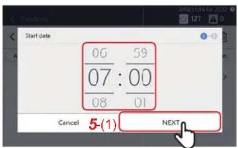
5 Tap or flick to set the start time and tap [5-(1)]
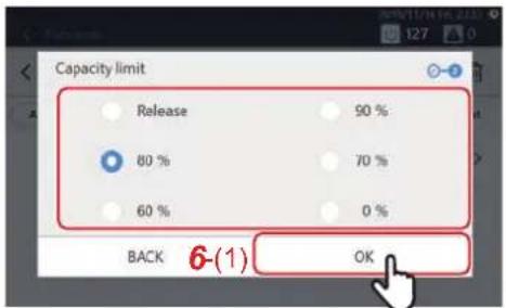
6 Select the outdoor demand level and tap [6-(1)] to add a demand schedule
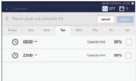
7 To add a schedule such as change/release of demand level, repeat steps 4 to 6
NOTE
- The outdoor demand initiated by the schedule is released in the following cases.
- When demand release is set in the schedule
- When demand control of the outdoor unit has been released (P.59)
- Demand control continues even across days. Example: When the demand rate is set to 0% on Monday at 13:00 and release is set at 6:00 on Tuesday
→ The demand rate is set to 0% from Monday at 13:00 to Tuesday at 6:00 and demand release occurs at 6:00 on Tuesday
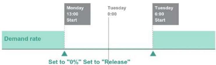
flowchart
graph LR
    A["Demand rate"] --> B["Monday 13:00 Start"]
    B --> C["Tuesday 0:00"]
    C --> D["Tuesday 6:00 Start"]
    style A fill:#f9f,stroke:#333
    style B fill:#ccf,stroke:#333
    style C fill:#cfc,stroke:#333
    style D fill:#fcc,stroke:#333
    note bottom of A: Set to "0%" Set to "Release"
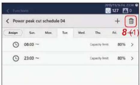
8 Tap [8-(1)] and set the check box of the demand setting you want to delete to , then tap "delete"
Delete an Power peak cut schedule
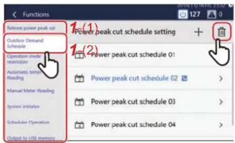
1 Tap [1-(2)] with [1-(1)] (P.59)
2Tap

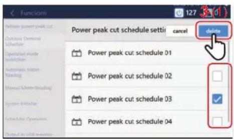
3Set the check box of the schedule you want to delete to √, then tap [3-(1)]
The selected schedule will be deleted.
NOTE
Also, when deleting a registered time, tap and operate similarly.
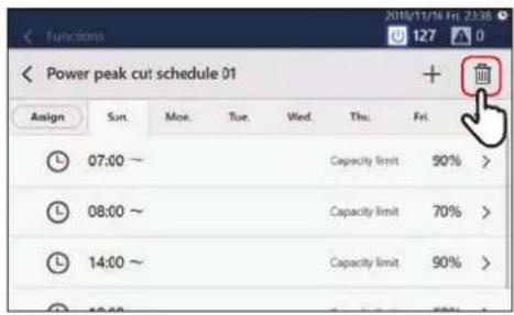
Restrict operation mode (Operation mode restriction)
When using an outdoor unit that cannot operate cooling and heating at the same time, you can restrict its operation mode so that it can only be set for either cooling or heating.
1 Tap [Operation mode restriction] in the [Functions] menu (P.59)
2Select the operation mode and tap [OK]
NOTE
- Settings are reflected in all outdoor units.
- Even with restriction, the operation mode of the [CONTROL] tab can be selected. When a restricted operation mode is selected, the Thermo OFF state is set.
Restart the Unit (System reboot)
You can restart the Unit if its operation becomes unstable.
The schedule is not executed during restart.
1 Tap [System reboot] in the [Functions] menu (P.59)
2Tap [OK]
Set the operating schedule or the power peak cut schedule (Scheduler Operation)
You can disable registered Operation Schedules and Power peak cut schedules so that they do not operate.
1 Tap [Scheduler Operation] in the [Functions] menu (P.59)
2 Set the check box to √ if you do not want to operate each schedule, or set the check box to □ to operate them, then tap [OK]
Output data to a USB memory stick (Output to USB memory)
You can output monthly report/daily report files for power allocation, alarm files, or setting files to a USB memory stick.
1Connect the USB memory stick to the slot in the Unit
2Tap [Output to USB memory] in the [Functions] menu (P.59)
3Tap [OK]
NOTE
If the USB memory stick is not connected, [OK] will not be enabled.
[Initial setting] Menu Settings
On the [Initial setting] menu, you can change the Unit screen display and the settings for remote operation, etc.
How to display the [Initial setting] menu
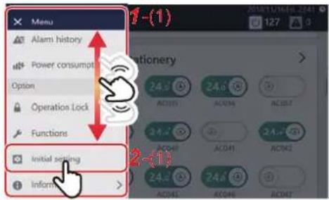
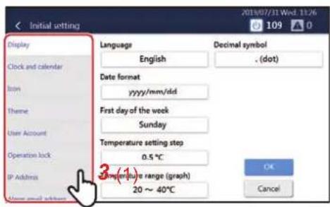
1Tap

[1-(1)] appears.
2 Scroll through the menu list and tap [2-(1)]
[3-(1)] appears.
3 Tap the item you want to set with [3-(1)]
The settings screen of the selected item appears on the right.
For details on the setting contents of each item, refer to the following.
• Display Settings (P.64)
• Clock and calendar setting (P.64)
- Icon settings (P.65)
- Theme Settings (P.65)
- User Account Setting (P.66)
• Operation lock Setting (P.68)
• IP Address Setting (P.69)
• Alarm email address setting (P.70)
- Indoor unit area setting (P.71)
- Indoor unit name setting (P.72)
• Area name setting (P.72)
- Backlight setting (P.73)
Set the screen display (Display)
You can change the display settings of the screen, such as language and date display format.
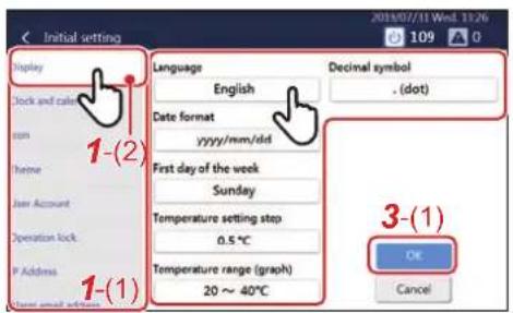
1 Tap [1-(2)] with [1-(1)] (P.63) 2 Tap the item you want to change
Language: You can change the display language of the screen.
Date format: You can change the format of the date displayed in the upper right of the screen.
First day of the week: You can change the first day of the week displayed on the calendar or schedule to Sunday or Monday.
Temperature setting step: You can change the temperature setting step to 0.5°C or 1°C. However, it cannot be changed if the display unit is Fahrenheit.
Temperature range (graph): You can change the temperature range displayed on the [GRAPH] tab.
Decimal symbol: You can change the decimal symbol displayed on the screen between [. (dot)] and [, (comma)].
3 Select the value you want to change, then tap [3-(1)]
Set the current date and time (Clock and calendar)
You can change the date and time displayed in the upper right of the screen.
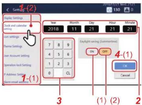
1 Tap [1-(2)] with [1-(1)] (P.63)
2Tap the item you want to change
The background of the selected item changes to white.
3Tap the numeric keypad to enter a number
4 Tap [4-(1)]
NOTE
You can set daylight saving time with [Daylight-saving (Summertime)]. When set to [(1)], the time moves one hour forward, and when set to [(2)], it moves one hour back. While daylight saving time is set, 📄 appears in the upper right corner of the screen.
Set icons of devices other than air conditioners (Icon)
You can display icons of each device on the [CONTROL] tab of devices other than air conditioners such as ventilation fan or lighting.
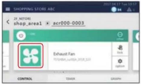
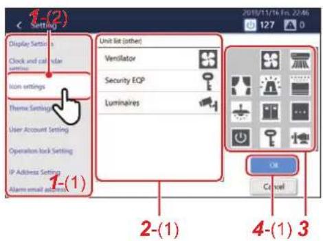
1 Tap [1-(2)] with [1-(1)] (P.63)
2 Tap the device you want to set with [2-(1)]
3Tap the icon you want to set in the icon list
The selected icon is displayed in [2-(1)].
4 Tap [4-(1)]
NOTE
- To delete a set icon, select the device with [2-(1)] and then tap the space at the top left of the icon list.
• The following icons can be set:
 | Ventilation fan/Circulator |  | Room air conditioner |  | Curtain Alarm |  | |  | Dehumidifier |  | Lighting |
 | Cubicle Water |  | storage tank |  | General switch |  | Security Pump | Camera  |  |
Set the screen theme (Theme)
You can set the theme of the home screen and the details/control screen.
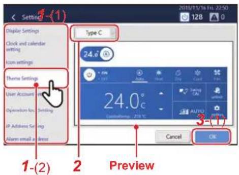
1 Tap [1-(2)] with [1-(1)] (P.63)
2Tap the drop-down menu and select a theme
The selected theme appears in the preview. Operate the switch or tap the power supply or operation mode button to check the display after the change.
3 Tap [3-(1)]
Set an account for remote operation (User Account)
You can set a user account to operate the Unit remotely.
* Remote operation can be used when the Unit is connected via LAN to a PC on which the Remote Control Software is installed.
NOTE
• 128 users can be registered.
- Up to 16 users can log in at the same time.
- At least one user must be registered.
Add/change user account
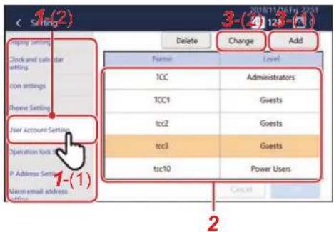
1 Tap [1-(2)] with [1-(1)] (P.63)
2To change, tap the row you want to change in the list
NOTE
The following users are registered in advance.
You can also change/delete users.
Name: TCC
Password: TCC
Level: Administrators
3 Tap [3-(1)] or [3-(2)]
In the following procedure, the screen in the case of addition is used to explain.
4 Set Name (only when adding) and password
Tap the entry field to display the keyboard. After entering the characters, tap [4-(1)].
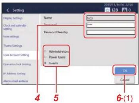
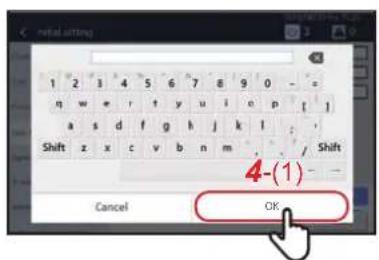
NOTE
- Tap [Shift] to toggle between upper case letters and lower case letters, and numbers and symbols.
- Tap to delete one character.
5Set level
Administrators : All functions can be used.
Power Users : The following functions cannot be used.
- Confirm/change the operation schedule
- [Menu] > Functions
- [Menu] > Initial setting
Guests : Only the operation status can be confirmed. The settings cannot be changed.
NOTE
For details on the functions that can be used for each level, see "List by Lock Level/Level" (P.84).
6 Tap [6-(1)]
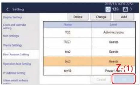
7 Tap [7-(1)]
Delete a user account
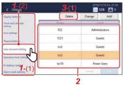
1 Tap [1-(2)] with [1-(1)] (P.63)
2Tap the row you want to delete
3 Tap [3-(1)] It will be deleted from the list.
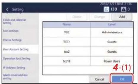
4 Tap [4-(1)] Deletion is confirmed.
Set the operation lock level (Operation lock)
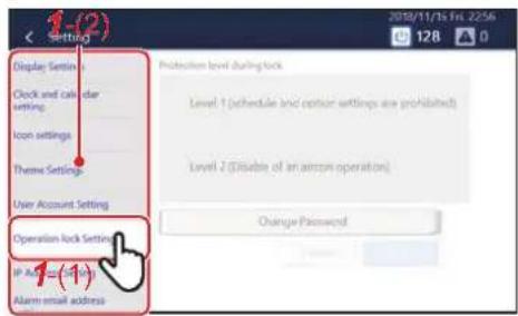
1 Tap [1-(2)] with [1-(1)] (P.63)
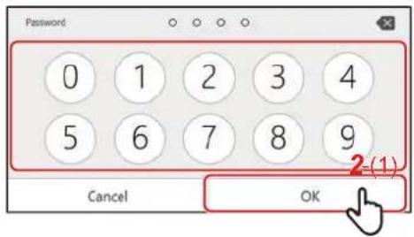
2 Enter the password and tap [2-(1)]
NOTE
The factory default setting password is "1048".
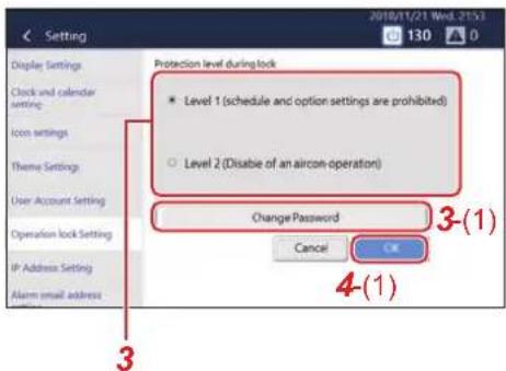
3Select the protection level during lock
NOTE
You can change the password that sets the operation lock.
Tap [3-(1)] to display the change password input screen.
Enter the changed password, tap [OK], re-enter it on the re-entry screen, then tap [OK].
4-digit passwords can be set.
4 Tap [4-(1)]
Set the IP address of the Touch Screen Controller (IP Address)
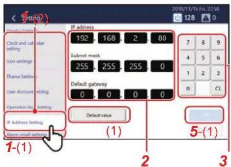
1 Tap [1-(2)] with [1-(1)] (P.63)
2Tap the value you want to change
The background of the selected item changes to white.
3Tap the numeric keypad to enter a number
4If there are other values you want to change, repeat steps 2 and 3
5 Tap [5-(1)]
The IP address is reset.
NOTE
• The initial setting is as follows:
IP address: 192.168.2.80
Subnet mask: 255.255.255.0
Default gateway: 0.0.0.0
- To return a changed value to the specified value, tap [(1)]. Tap [OK] on the confirmation screen to reset the IP address.
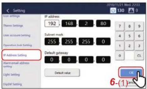
6 Tap [6-(1)]
The Unit restarts.
Set alarm email destination (Alarm email address)
You can set the email address to send email to when an alarm occurs.
NOTE
Up to five email addresses can be set.
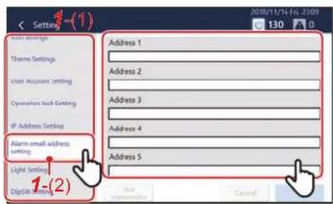
1 Tap [1-(2)] with [1-(1)] (P.63)
2Tap the address field to register
![Initial setting Address 1 1 2 3 4 5 6 7 8 9 0 - = q w e r t y u i o p [ ] a s d f g h j k l ; Shift z x c v b n m / Shift Cancel 3(1) OK](/content/2026/05/959133/images/c5c6e7a949efee4b99636b3cbd02bd7f6f29e7d30db81490b12b41755e9511a4.jpg)
3 Enter the email address on the keyboard, then tap [3-(1)]
NOTE
- Tap [Shift] to toggle between upper case letters and lower case letters, and numbers and symbols.
- Tap to delete one character.
4Tap [OK]
NOTE
To test-send to the registered email address, tap [Test transmission], which displays after you tap [OK].
Change the area set for an indoor unit (Indoor unit area setting)
In [Indoor unit area setting], you can move the indoor unit A in area X to area Y.
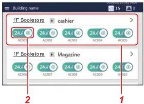
NOTE
• [1] All areas. The area numbers, such as area 1 and area 2, are allocated automatically in the upper section of the home screen.
• [2] Each indoor unit in the area.
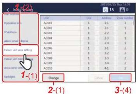
The procedure below is used as an example to explain how to move the indoor unit (AC001) set in area 1 to area 2.
1 Tap [1-(2)] in [1-(1)] (P.63)
2 Tap [2-(1)]
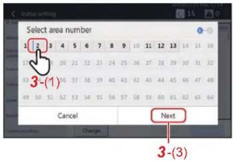
3 Tap [3-(1)]
Set the check box of the indoor unit (AC001) you want to move to area 2 to and then tap [3-(2)], [3-(3)], and [3-(4)].
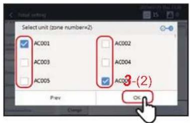
The indoor unit (AC001) is moved to area 2.
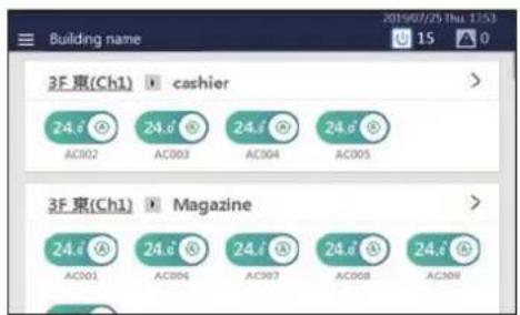
Set the name of an indoor unit (Indoor unit name setting)
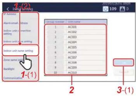
1 Tap [1-(2)] in [1-(1)] (P.63)
2Tap the name you want to change in the list
A keyboard is displayed. Enter the name and then tap [2-(1)].
![AC001 q w e r t y u i o p [ ] a s d f g h j k i ; Shift z x c v b n m / Shift Cancel 2-(1) OK](/content/2026/05/959133/images/ce93ce000319003e5b6560786595e6905eebb2f335fb8ad54868bc21f9354444.jpg)
NOTE
- Tap [Shift] to toggle between upper case letters and lower case letters, and numbers and symbols.
- Tap to delete one character.
3 Tap [3-(1)]
Set the area name (Area name setting)
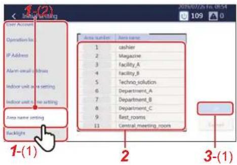
1 Tap [1-(2)] in [1-(1)] (P.63)
2Tap the name you want to change in the list
A keyboard is displayed. Enter the name and then tap [2-(1)].
![Cathier 1 2 3 4 5 6 7 8 9 0 q w e r t y u i o p [ ] a s d f g h j k l : Shift z x c v b n m / Shift Cancel OK](/content/2026/05/959133/images/f11c4c519b0480069ba7d2250cca16dfeab58fc0e1a9a9c6b3500d9060fed8a1.jpg)
NOTE
- Tap [Shift] to toggle between upper case letters and lower case letters, and numbers and symbols.
- Tap to delete one character.
3 Tap [3-(1)]
Set the screen brightness (Backlight)
You can set the brightness of the screen and the duration after the end of the operation. (30, 60, 360, or 720 minutes later)
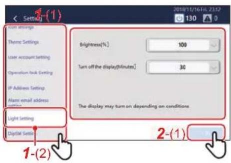
1 Tap [1-(2)] with [1-(1)] (P.63)
2 Select the brightness and tap [2-(1)]
9Remote monitoring using a PC
You can monitor and control the Unit by accessing it from a PC. This section explains the system diagram and the operating environment. For settings, etc., see "Settings for Remote Monitoring with a PC" (P.21).
NOTE
Some functions cannot be used from a PC. For details, please see "List by Lock Level/Level" (P.84).
Log in to Remote Control Software
NOTE
Up to 16 users can log in at the same time.
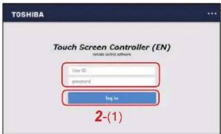
1 Double-click "AMTC\_UI\_\*\*\*\*" on the desktop
2 Enter [User ID] [password], then click [2-(1)]
User ID/password:
Use the user account set up in step 1 of "Unit settings" (P.22).
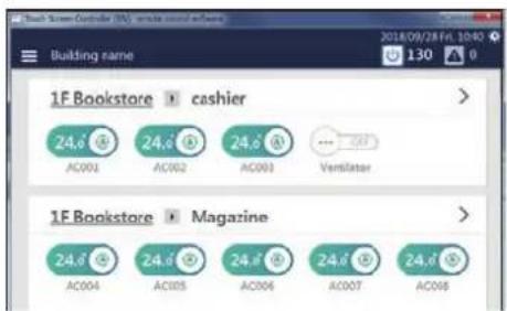
The Remote Control Software home screen is displayed.
Log out from Remote Control Software
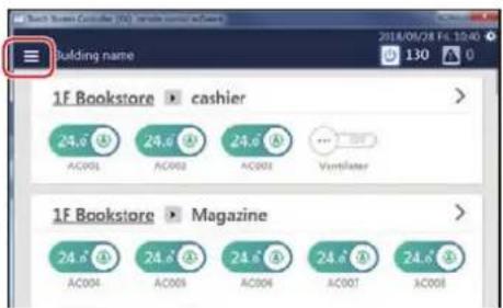
1Click

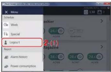
2 Click [2-(1)]
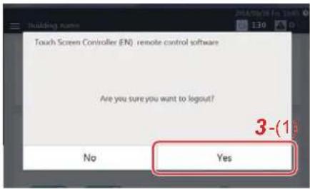
3 Click [3-(1)] You are logged out from the Remote Control Software.
Exit Remote Control Software
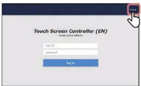
1Tap
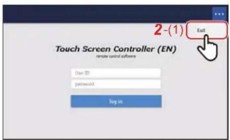
2 Tap [2-(1)]
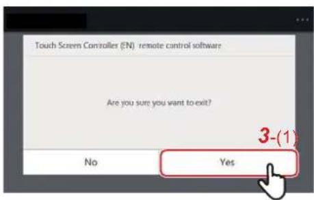
3 Tap [3-(1)] Exit the Remote Control Software.
10Power allocation
Electric Power Allocation System that can be Used with this Unit
In normal houses, a contract is made with the electric power company for each house, but in buildings such as offices and shops, a contract is made between the building owner and the electric power company, and the building owner pays the total electricity bill. Therefore, in some cases the building owner allocates the electricity fee that they paid in bulk to each tenant and invoices for a fee.
With this Unit, you can record the operating time of the air conditioner(s) and the ON/OFF unit, and distribute the electric power of each device based on that data.
In addition, by using the Report Creation Software, you can easily summarize the operation results in a report format and calculate the billing amount.
Example report
This system calculates the allocation of the power by load ratio estimated for each air conditioner. The result may differ from the actual power consumed. In addition, the result is not calculated based on the Measurement Act and cannot be used officially.
System diagram
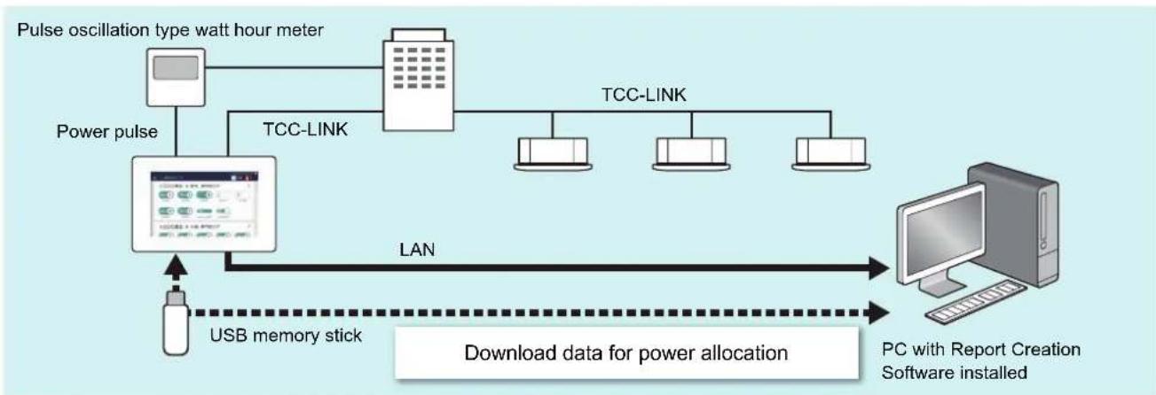
flowchart
graph TD
    A["Pulse oscillation type watt hour meter"] --> B["Power pulse"]
    B --> C["TCC-LINK"]
    C --> D["TCC-LINK"]
    D --> E["Computer"]
    F["USB memory stick"] --> G["Download data for power allocation"]
    G --> H["PC with Report Creation Software installed"]
    style A fill:#f9f,stroke:#333
    style B fill:#ccf,stroke:#333
    style C fill:#cfc,stroke:#333
    style D fill:#fcc,stroke:#333
    style E fill:#cff,stroke:#333
    style F fill:#ffc,stroke:#333
    style G fill:#cfc,stroke:#333
    style H fill:#fcc,stroke:#333
Power Allocation System
In order to perform power allocation, it is necessary to sum the data for power allocation. Summing may be done by automatic meter-reading or manual meter-reading.
Set the summation date of the power allocation data (Automatic Meter-Reading)
You can set the date for automatic meter-reading of the power allocation data. Automatic meter-reading is carried out on the set date, and data from the previous meter-reading date to the set date is output as a monthly report file.
It can be set according to the convenience of the building owner or tenant. For example, it is possible to sum over a period as follows.
- Sum to the end of the month each month (Set the automatic meter-reading day to the end of the month and sum from the 1st to the end of the month)
- Sum to the 15th of every month (Set the 15th of the month as the automatic meter-reading day and sum from the 16th of the previous month to the 15th of the current month)
- Sum by dividing each month into two (Set the 15th of the month and the end of the month as the automatic meter-reading days and sum twice, from the 1st to the 15th and from the 16th to the end of the month)
- Sum two months (Set the end of every other month as the meter-reading day and sum from the 1st of the preceding month to the end of the current month)
By setting automatic meter-reading, you can use the system for monthly electricity billing.
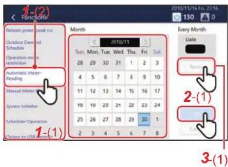
1 Tap [1-(2)] with [1-(1)] (P.59)
2 Select the day you want to meter-read on the calendar and tap [2-(1)]
NOTE
- You can set the schedule for one year from the current month.
- You can set up to two days for every month. Months without meter-reading can also be set.
- Tap the selected day again to release the setting.
- The meter-reading result file (monthly report/daily report file) can be output to a USB memory stick. (P.63)
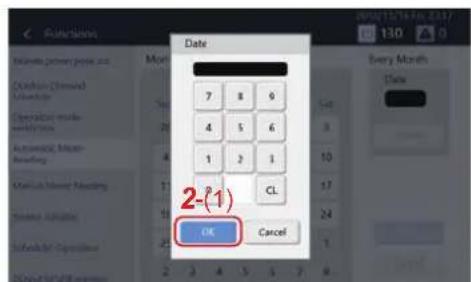
◆ To batch set meter-reading days
1Tap
2 Tap a number, enter the date, then tap [2-(1)]
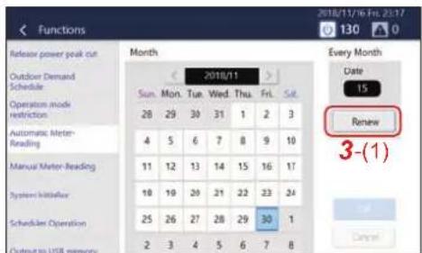
3 Tap [3-(1)]
Sum data for power allocation as necessary (Manual Meter-Reading)
You can manually meter-read the data for power allocation from the previous meter-reading day until the current day. Manual meter-reading is convenient if you need to sum data for power allocation before the automatic meter-reading day, such as when a tenant leaves.
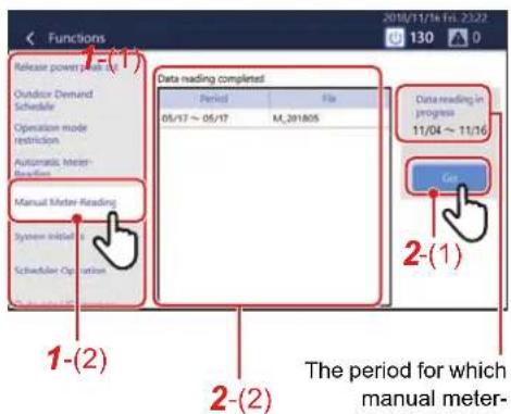
The file names of automatic or manual meter-readings and meter-reading periods are displayed in a list.
The period for which manual meter-reading is carried out (the previous meter-reading day to the current day) is displayed.
1 Tap [1-(2)] with [1-(1)] (P.59)
2 Tap [2-(1)]
The meter-reading result file is added to [2-(2)].
NOTE
The meter-reading result file (monthly report/daily report file) can be output to a USB memory stick. (P.63)
How to use the power allocation system
1 Download the data for power allocation
Save the data for power allocation to the PC using one of the following procedures.
1) Download by LAN connection
Download the data using the Report Creation Software.
2) Copy the data to a USB memory stick
Output the data to the USB memory stick using the Unit's [Output to USB memory] and import the data using the Report Creation Software.
2 Create monthly reports and daily reports
Create a monthly report or daily report from [Run] - [Download & create monthly/daily report] in the Report Creation Software.
3Click the month or day you want to display
4Click the [View report] button
NOTE
For details, refer to the instruction manual of the Report Creation Software.
11Troubleshooting
| Phenomenon Question Confirmation items | ||
| The LCD does not display. | Is the power turned on? | Check that the power is not turned off by the breaker or the like. There is a green LED at the lower rear of the main unit and a green LED on the AC adapter that indicate that power is being supplied. |
| Check that the wiring of the power outlet and AC adapter is not disconnected.There is a green LED at the lower rear of the main unit and a green LED on the AC adapter that indicate that power is being supplied. | ||
| Has the backlight gone out? | The LCD turns off when there is no operation for a certain period of time. Touch the touch panel to turn on. The brightness and display time can be changed using [Backlight]. | |
| Is the backlight brightness dark? Adjust the brightness using [Backlight]. | ||
| The operated air conditioner does not run. | Does the operated air conditioner match the actual air conditioner? | Operate another air conditioner and check if the actual air conditioner operates. |
| Is an alarm occurring? | The air conditioner will not operate when an alarm is occurring. Turn off the alarm. | |
| Are you operating with the local remote control? | Even if the air conditioner is run with this Unit, if it is stopped afterwards with the local remote control, it will stop. The latter operation of this Unit or the local remote control overrides the former. | |
| Is the air conditioner stopped due to the schedule setting of the local remote control or the like? | Even if the air conditioner is run with this Unit, if it is stopped afterwards with the local remote control schedule, it will stop. The latter operation of this Unit or the local remote control overrides the former. | |
| Are you operating with the PC app "Remote Control Software"? | Even if the air conditioner is run with this Unit, if it is stopped afterwards with the PC app "Remote Control Software", it will stop. The latter operation of this Unit or the "Remote Control Software" overrides the former. | |
| I want to turn off the power. | There is no power switch. | Please remove the AC adapter or turn off the circuit breaker. |
| I want to reboot. | Reboot from the menu. | Select [Menu] - [Functions] - [System reboot]. |
| The air conditioner settings change arbitrarily. | Are you operating with the local remote control? | Even if the air conditioner is run with this Unit, if it is stopped afterwards with the local remote control, it will stop. The latter operation of this Unit or the local remote control overrides the former. |
| Is the air conditioner stopped due to the schedule setting of the local remote control or the like? | Even if the air conditioner is run with this Unit, if it is stopped afterwards with the local remote control schedule,it will stop. The latter operation of this Unit or the local remote control overrides the former. | |
| Have you applied settings such as stop using an external input signal? | When stop, etc. is set by an external input signal using the external interlocking function, the air conditioner stops automatically when a signal is input. | |
| Are you operating with the PC app "Remote Control Software"? | Even if the air conditioner is run with this Unit, if it is stopped afterwards with the PC app "Remote Control Software", it will stop. The latter operation of this Unit or the "Remote Control Software" overrides the former. | |
| The schedule does not work. | Is the schedule disabled? | Please confirm the Scheduler Operation settings. |
| Does the scheduled air conditioner match the actual air conditioner? | Operate another air conditioner and check if the actual air conditioner operates. | |
| Is a Particular Timer setting set? | If a day is set in both the Week Schedule and a Particular Timer setting, the Particular Timer setting will apply for that day. | |
| The air conditioner doesn't cool. The air conditioner doesn't heat. | Is demand control turned on? | Demand control suppresses the capability of the outdoor unit in order to reduce power consumption. Therefore, it may take time to reach the set temperature. |
| Is the forced thermo OFF control turned on? | Forced thermo OFF is a control to stop the operation of the outdoor unit. Therefore, the indoor unit acts as a fan. | |
| Is the power saving control turned on? | Power saving suppresses the capability of the outdoor unit. Therefore, it may take time to reach the set temperature. | |
| The LCD does not turn off. | Is an alarm occurring? | The LCD will still be on when an alarm is occurring. Turn off the alarm. |
| Sometimes the LCD becomes black for a moment. | The LCD's antistatic control is working. | Temporarily stop the LCD periodically to prevent LCD burn-in. Not a malfunction. |
| The setting displayed on the local remote control does not match the setting displayed on this Unit. | Does the operated air conditioner match the actual air conditioner? | Operate another air conditioner and check if the actual air conditioner operates. |
| I would like to frequently change detailed settings such as set temp. and setting mode for all air conditioners. | Only "ON" and "OFF" can operate all air conditioners at once. | You can set the set temp., setting mode, etc. for each air conditioner group by group. Please group the air conditioners. |
| When local remote control operation is prohibited, if there is a power failure, the local remote control prohibited status will be cancelled when the power returns. | - Ask service personnel if you want to continue the local remote control prohibited status after returning from a power failure. | |
| FILTER information can be reset even when the FILTER sign is not displayed. | The FILTER signs lights up depending on the accumulated operation time. | As the operation time accumulates, the FILTER sign lights up when the preset operation time is reached.The FILTER sign information can be reset to clear the accumulated time for cases such as when FILTER cleaning is carried out before the FILTER sign turns on. |
| I want to check the software version. | Reboot from the menu. The version is displayed under [Menu] - [Information]. | |
| Reboot from time to time. Please check for noise and the power supply status. | The main unit may restart if noise in the surroundings or an unstable power supply cause the operation of the software to be unstable.Please check the surrounding environment. | |
| I cannot start the Remote Control Software. | Is "Error 1001" displayed? | Please download .Net Framework 4.6.2 from the download website of this software and install it. |
| Is the LAN cable connected? | This software will not start unless the PC and the LAN of this Unit are connected. Check the LAN cable connection and network settings. | |
| Is the IP address of the access destination set to the IP address of the controller main unit? | The IP address (or server name) to be entered during installation is the IP address of the controller main unit. It is not the IP address of the PC.If it is incorrect, please do the following and then reinstall.1. Uninstall the application2. Delete the install destination directory3. Delete the desktop and start menu shortcuts | |
| Is the PC on which the software was installed Windows 8.1 or 10? | Windows 8.1 and 10 are supported. The software may not operate correctly when installed on a PC with a different OS. | |
| I cannot log in to the Remote Control Software. | Have you logged in as the same user from another PC? | Each user can log in from only one PC at the same time. |
| Is the Windows display style set to classic style? | Please select a display style other than classic style.You can change the display style from [Start] - [Control Panel] - [Appearance and Personalization] - [Change the theme]. This software supports Windows 8.1 and 10. | |
| I cannot log in to Remote Control Software from another PC after the LAN is disconnected. | Have you logged in with the same user ID? | You must log in again from a PC with the LAN disconnected and log out normally. |
| Have you accessed the software from more than 8 PCs? | Up to 8 PCs can be accessed at the same time. The software may not operate correctly if you connect to more than 9 PCs. | |
| Did you assign the PC's IP address using a DHCP server? | This Unit judges whether it is accessed from the same PC using the IP address.If the PC address is changed partway through by the DHCP server, you may not be able to log in again after LAN disconnection. Please set the PC that accesses this Unit to a fixed IP or reboot the Unit and erase the login information. | |
| The language does not switch with the Remote Control Software. | Does the login user for the Windows being used have write permission for the Remote Control Software storage location? | Please allow write permission below the folder where Remote Control Software is saved (initial setting: C:\Program Files\TOSHIBA Carrier Corporation).Right-click on the TOSHIBA Carrier Corporation folder, select the [Properties] - [Security] Name, click the "Edit" button and check [Allow] for [Full control] under different settings. |
| The schedule setting changes have not been reflected. | Are you trying to change the schedule settings on both the Remote Control Software and the main unit? | To change the schedule settings, please set only one of either the main unit or the Remote Control Software. |
| I would like to use the software with other centralized controllers. | Centralized controllers that can be used together within the same TCC-LINK. | It is possible to use up to 8 units together with all centralized controllers including this Unit.Ask service personnel to use them in combination. |
| I want to use multiple units in combination. | Number of units that can be used in combination in the same TCC-LINK. | It is possible to use up to 8 units together with all centralized controllers including this Unit.Ask service personnel to use them in combination. |
| The LCD sometimes turns black for a moment. | The LCD's antistatic control is working. | This is not a malfunction. The LCD may turn black temporarily to remove static electricity. |
| The multi outdoor unit's option board control does not work. | Do you want to use the multi outdoor unit's option board? | When the centralized controller is connected, the functions of the outdoor unit's option board become ineffective. Only one of the centralized controller and the outdoor unit's option board can be used. |
| The Unit does turn ON/OFF even though the operation interlock signal/stop interlock signal is input. | Has the interlock signal been input from the time of activation? | Since the interlock signal confirms the state by detecting the rising edge and falling edge, if the interlock signal is input from the time of activation, interlock control will not be performed. Please set so that the interlock signal turns OFF at the time of activation. |
12Useful information
The following cases are not faults with the Unit.
| Problem Cause | |
| When an air conditioner is stopped, its operation status is displayed on the LCD display part of the Touch Screen Controller. | This is because even when an air conditioner is stopped, you can set its operation from the Touch Screen Controller. |
| The display does not switch even if you operate the Touch Screen Controller. | · The function is not provided by the air conditioner.· There may be an error in the operation method. Please check the operation explanation of the function.· This is because switching of HEAT and COOL in the operation mode is prohibited. |
| It is not set even when operating the Touch Screen Controller. |
Please check the following before requesting service.
| Problem Cause Solution | ||
| The air conditioner does not operate even when I press the Run/Stop switch on the Touch Screen Controller. | Has a power outage occurred? | If the LCD of the Touch Screen Controller does not display, press the ON/OFF button of the Touch Screen Controller again after energizing the controller. |
| The check lamp of the Touch Screen Controller lights up. | Is the air conditioner protection device operating? | Please see the air conditioner operation manual and check the operation. |
| On the LCD display part of the Touch Screen Controller (Abnormality) and the check code C06 is displayed. | Is a power outage affecting the air conditioner? | After restoring power to the air conditioner, the display will disappear after waiting a few minutes. |
If you have investigated the above and there is still an abnormality, please contact the dealer from whom you purchased the Unit with the part number and problem.
Under no circumstances conduct repairs by yourself. Doing so is dangerous.
Moreover, if the LCD display part of the Touch Screen Controller displays ⚠ (Abnormality) and a check code, please also inform the dealer of these items.
13Appendix
Specifications
Detailed specifications
| Power supply 120 V AC 60 Hz | |
| Operating temperature/humidity range | 32°F to 104°F (0°C to 40°C), 10% to 90% RH (no dew condensation) |
| Dimensions: inch (mm) | H5.35"×W8.07"×D0.39" (H136 mm×W205 mm×D10 mm)(+3.15" (+80 mm))(Embedded dimensions shown in parenthesis) |
| Mass | 2.95 lb (1.34 kg) (Touch Screen Controller)0.99 lb (0.45 kg) (power adapter) |
| LCD | Type 7 TFT liquid crystal, 800×480, 16,700,000 colours(Luminance 800 cd/m2, contrast ratio 600:1) |
| Touch Screen Projection-capacitive type | |
| Communication ports | ·RS-485 port ×1(for connecting four digital I/O interfaces and four watt hour meter interfaces)·LAN port ×1 (for connecting PC) |
| USB port USB memory stick connection port ×2 | |
| External contact input 8 inputs | |
| External contact output 4 inputs | |
| Included PC software(Requires a separate PC (*1)) | ·Remote Control Software·Report Creation Software·Section Changeover Software·Data Analyzer |
*1 Conditions for PC connection (operating environment)
OS: Windows 8.1 or Windows 10
LAN port: 10BASE-T or 100BASE-TX wired LAN port
Other: mouse/keyboard, printer (if printing is required)
Function list
| Key Features | |
| Control | ON/OFF |
| Setting mode | |
| Set temp. | |
| Fan speed settings | |
| Swing ON | |
| Local remote controller operation lock/unlock | |
| Ventilation → ON/OFF | |
| Ventilation → Mode | |
| Ventilation → Fan speed | |
| Soft Cooling | |
| Energy saving ratio [%] | |
| Eco Temperature Shift | |
| Set temp. range limit | |
| Filter Sign Reset | |
| Monitoring | ON/OFF |
| Setting mode | |
| Set temp. | |
| Fan speed settings | |
| Swing ON | |
| Local remote controller operation lock/unlock | |
| Ventilation → ON/OFF | |
| Ventilation → Mode | |
| Ventilation → Fan speed | |
| Soft Cooling | |
| Energy saving ratio [%] | |
| Eco Temperature Shift | |
| Set temp.range limit | |
| Outdoor temp. | |
| Power Level | |
| Return Back | |
| Power peak cut | |
| FILTER Sign | |
| Schedule | Setting unit (Per unit) |
| Setting unit: Week Schedule (per day of the week) | |
| Setting unit: Particular Timer setting (per date) | |
| Setting time (00:00 to 23:59) | |
| ON/OFF | |
| Setting mode | |
| Set temp. | |
| Local remote controller operation lock/unlock | |
| Return Back | |
| Energy saving ratio [%] | |
| Ventilation operation setting | |
| Vent. Mode | |
| Maximum number of schedules per day 64 | |
| Key Features | |||
| External input | Inputs | Main unit 8 inputs | |
| DIO interface 8 inputs x 4 units | |||
| Functions | Power pulse measurement | ||
| Demand Interlocking | |||
| Fire Alarm Interlocking | |||
| Security Interlocking | |||
| Stop Interlocking | |||
| Operation Interlocking | |||
| For ON/OFF indication | |||
| For alarm indication | |||
| External output | Outputs | Main unit 4 outputs | |
| DIO interface 4 outputs x 4 units | |||
| Functions | Alarm Output Interlocking | ||
| Operation Output Interlocking | |||
| Controller Error Output Interlocking | |||
| For ON/OFF control | |||
Glossary
Power peak cut
The maximum demand power, which is the power value used to calculate the electricity fee from the electric power company.
The monthly electricity fee is composed of the "basic fee" and the "power fee". The "power fee" is calculated according to the usage of electricity in the month, but the "basic fee" is determined according to the month when the Power peak cut was the highest in the past year. Since the time when Power peak cut increases, such as summer, is limited, keeping Power peak cut to the average is a key point to reduce the basic fee.
◆During power peak cut control
Control to cut the peak of electric power usage.
Flap
A part that changes the air direction at the outlet. It is also called a louvre.
◆ON/OFF unit
Indicates devices that cannot control or monitor set temperature or setting mode among the managed devices. Main equipment includes lighting settings, air to air heat exchangers, ventilation fans, etc.
Thermo OFF
An energy saving function whereby when the temperature of a room reaches the set temperature, the outdoor unit compressor stops to switch from cooling/heating to fan operation.
Although the indoor unit (air conditioner) is in operation, the outdoor unit repeatedly turns ON/OFF depending on the room temperature.
List by Lock Level/Level
Refer to the following table for the functional differences depending on the operation of the main Unit and remote operation, the level of the operation lock of the main Unit and the level of the user account.
(O: Full functional operation △: Partially restricted -: Cannot be used)
| Item | Unit Operation Remote Operation | ||||||
| Operation Lock None | Operation Lock - Level 1 | Operation Lock - Level 2 | Administrators | Power Users | Guests | ||
| Home screen ○ ○ △ ○ ○ △ | |||||||
| Group screen | [CONTROL] tab | ○ | ○ | - | ○ | ○ | - |
| [SCHEDULE] tab ○ -- ○ -- | |||||||
| [GRAPH] tab ○ ○ -- ○ ○ - | |||||||
| Individual control screen | [CONTROL] tab ○ ○ -- ○ ○ - | ||||||
| [SCHEDULE] tab ○ -- ○ -- | |||||||
| [GRAPH] tab ○ ○ -- ○ ○ - | |||||||
| SCHEDULE | Week Schedule ○ -- ○ -- | ||||||
| Particular Timer setting ○ -- ○ -- | |||||||
| Batch ON/OFF screen ○ ○ △ ○ ○ △ | |||||||
| Alarm history screen ○ ○ △ ○ ○ △ | |||||||
| Item | Unit Operation | Remote Operation | ||||||
| Operation Lock None | Operation Lock - Level 1 | Operation Lock - Level 2 | Administ rators | Power Users | Guests | |||
| Menu Operation | lock screen ○ ○ ○ ○ ○ ○ | |||||||
| Alarm History ○ ○ ○ ○ ○ ○ | ||||||||
| Electric power ○ ○ ○ ○ ○ ○ | ||||||||
| Functions | Release power peak cut | ○ | - | - | ○ | - | - | |
| Power peak cut schedule ○ | - - ○ | - - | ||||||
| Operation mode restriction | ○ | - | - | ○ | - | - | ||
| Automatic Meter-Reading ○ | - - ○ | - - | ||||||
| Manual Meter-Reading ○ - | - ○ - | - | ||||||
| System initialize ○ - - ○ | - - | |||||||
| Scheduler Operation ○ - - | ○ - | - | ||||||
| Output to USB Memory ○ - | - - - | - | ||||||
| Settings | Display Settings | ○ | - | - | ○ | - | - | |
| Clock and calendar setting | ○ | - | - | ○ | - | - | ||
| Icon settings | ○ | - | - | ○ | - | - | ||
| Theme Settings | ○ | - | - | ○ | - | - | ||
| User Account Setting | ○ - | - - - | - | |||||
| Operation Lock Setting ○ - | - ○ - | - | ||||||
| IP Address Setting | ○ - | - - - | - | |||||
| Alarm email address setting | ○ | - | - | - | - | - | ||
| Indoor unit area setting | ○ | - | - | - | - | - | ||
| Indoor unit name setting | ○ | - | - | - | - | - | ||
| Area name setting | ○ - | - - - | - | |||||
| Backlight setting | ○ - | - - - | - | |||||
| Support screen | ○ ○ | ○ ○ | ○ ○ | |||||
| Logout | - - | - ○ ○ | ○ | |||||
14 Warranty and after-sales service
About the Warranty
- The warranty period is one year from date of purchase.
About After-Sales Service
- Please check "11. Troubleshooting" (P.79) before requesting a repair. If this does not solve the problem, immediately shut off the power supply and contact us.
- Please inform us of the following when requesting a repair.
- Customer name
- Address, phone number
- Product model name and serial number
- Installation date
- Failure status (as much detail as possible)
Contact for after-sales service (Information)
For after-sales service, please contact here.
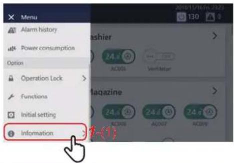
1 Tap ≡, then tap [1-(1)]
The contact information is displayed.
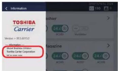
OSS License
This product contains licensed software or software whose copyright is owned by a third party according to the following.
OpenSSH
This file is part of the OpenSSH software.
The licences which components of this software fall under are as follows. First, we will summarize and say that all components are under a BSD licence, or a licence more free than that.
OpenSSH contains no GPL code.
1)
* Copyright (c) 1995 Tatu Ylonen ylo@cs.hut.fi, Espoo, Finland
* All rights reserved
*
* As far as I am concerned, the code I have written for this software
* can be used freely for any purpose. Any derived versions of this
* software must be clearly marked as such, and if the derived work is
* incompatible with the protocol description in the RFC file, it must be
* called by a name other than "ssh" or "Secure Shell".
[Tatu continues]
* However, I am not implying to give any licenses to any patents or
* copyrights held by third parties, and the software includes parts that
* are not under my direct control. As far as I know, all included
* source code is used in accordance with the relevant license agreements
* and can be used freely for any purpose (the GNU license being the most
* restrictive); see below for details.
[However, none of that term is relevant at this point in time. All of these restrictively licenced software components which he talks about have been removed from OpenSSH, i.e.,
- RSA is no longer included, found in the OpenSSL library
- IDEA is no longer included, its use is deprecated
- DES is now external, in the OpenSSL library
- GMP is no longer used, and instead we call BN code from OpenSSL
- Zlib is now external, in a library
- The make-ssh-known-hosts script is no longer included
- TSS has been removed
- MD5 is now external, in the OpenSSL library
- RC4 support has been replaced with ARC4 support from OpenSSL
- Blowfish is now external, in the OpenSSL library
[The licence continues]
Note that any information and cryptographic algorithms used in this software are publicly available on the Internet and at any major bookstore, scientific library, and patent office worldwide. More information can be found e.g. at "http://www.cs.hut.fi/crypto".
The legal status of this program is some combination of all these permissions and restrictions. Use only at your own responsibility. You will be responsible for any legal consequences yourself; I am not making any claims whether possessing or using this is legal or not in
your country, and I am not taking any responsibility on your behalf.
NO WARRANTY
BECAUSE THE PROGRAM IS LICENSED FREE OF CHARGE, THERE IS NO WARRANTY FOR THE PROGRAM, TO THE EXTENT PERMITTED BY APPLICABLE LAW. EXCEPT WHEN OTHERWISE STATED IN WRITING THE COPYRIGHT HOLDERS AND/OR OTHER PARTIES PROVIDE THE PROGRAM "AS IS" WITHOUT WARRANTY OF ANY KIND, EITHER EXPRESSED OR IMPLIED, INCLUDING, BUT NOT LIMITED TO, THE IMPLIED WARRANTIES OF MERCHANTABILITY AND FITNESS FOR A PARTICULAR PURPOSE. THE ENTIRE RISK AS TO THE QUALITY AND PERFORMANCE OF THE PROGRAM IS WITH YOU. SHOULD THE PROGRAM PROVE DEFECTIVE, YOU ASSUME THE COST OF ALL NECESSARY SERVICING, REPAIR OR CORRECTION.
IN NO EVENT UNLESS REQUIRED BY APPLICABLE LAW OR AGREED TO IN WRITING WILL ANY COPYRIGHT HOLDER, OR ANY OTHER PARTY WHO MAY MODIFY AND/OR REDISTRIBUTE THE PROGRAM AS PERMITTED ABOVE, BE LIABLE TO YOU FOR DAMAGES INCLUDING ANY GENERAL, SPECIAL, INCIDENTAL OR CONSEQUENTIAL DAMAGES ARISING OUT OF THE USE OR INABILITY TO USE THE PROGRAM (INCLUDING BUT NOT LIMITED TO LOSS OF DATA OR DATA BEING RENDERED INACCURATE OR LOSSES SUSTAINED BY YOU OR THIRD PARTIES OR A FAILURE OF THE PROGRAM TO OPERATE WITH ANY OTHER PROGRAMS), EVEN IF SUCH HOLDER OR OTHER PARTY HAS BEEN ADVISED OF THE POSSIBILITY OF SUCH DAMAGES.
3)
ssh-keyscan was contributed by David Mazieres under a BSD-style license.
* Copyright 1995, 1996 by David Mazieres dm@lcs.mit.edu.
* Modification and redistribution in source and binary forms is
* permitted provided that due credit is given to the author and the
* OpenBSD project by leaving this copyright notice intact.
4)
The Rijndael implementation by Vincent Rijmen, Antoon Bosselaers and Paulo Barreto is in the public domain and distributed with the following license:
* @version 3.0 (December 2000)
* Optimised ANSI C code for the Rijndael cipher (now AES)
* @author Vincent Rijmen vincent.rijmen@esat.kuleuven.ac.be
* @author Antoon Bosselaers antoon.bosselaers@esat.kuleuven.ac.be
* This code is hereby placed in the public domain.
* THIS SOFTWARE IS PROVIDED BY THE AUTHORS "AS IS" AND ANY EXPRESS
* OR IMPLIED WARRANTIES, INCLUDING, BUT NOT LIMITED TO, THE IMPLIED
* WARRANTIES OF MERCHANTABILITY AND FITNESS FOR A PARTICULAR PURPOSE
* ARE DISCLAIMED. IN NO EVENT SHALL THE AUTHORS OR CONTRIBUTORS BE
* LIABLE FOR ANY DIRECT, INDIRECT, INCIDENTAL, SPECIAL, EXEMPLARY, OR
* CONSEQUENTIAL DAMAGES (INCLUDING, BUT NOT LIMITED TO, PROCUREMENT OF
* SUBSTITUTE GOODS OR SERVICES; LOSS OF USE, DATA, OR PROFITS; OR
* BUSINESS INTERRUPTION) HOWEVER CAUSED AND ON ANY THEORY OF LIABILITY,
* WHETHER IN CONTRACT, STRICT LIABILITY, OR TORT (INCLUDING NEGLIGENCE
* OR OTHERWISE) ARISING IN ANY WAY OUT OF THE USE OF THIS SOFTWARE,
* EVEN IF ADVISED OF THE POSSIBILITY OF SUCH DAMAGE.
5)
One component of the ssh source code is under a 3-clause BSD license, held by the University of California, since we pulled these parts from original Berkeley code.
* Copyright (c) 1983, 1990, 1992, 1993, 1995
* The Regents of the University of California. All rights reserved.
* Redistribution and use in source and binary forms, with or without
* modification, are permitted provided that the following conditions
* are met:
* 1. Redistributions of source code must retain the above copyright
* notice, this list of conditions and the following disclaimer.
* 2. Redistributions in binary form must reproduce the above copyright
* notice, this list of conditions and the following disclaimer in the
* documentation and/or other materials provided with the distribution.
* 3. Neither the name of the University nor the names of its contributors
* may be used to endorse or promote products derived from this software
* without specific prior written permission.
* THIS SOFTWARE IS PROVIDED BY THE REGENTS AND CONTRIBUTORS "AS IS" AND
* ANY EXPRESS OR IMPLIED WARRANTIES, INCLUDING, BUT NOT LIMITED TO, THE
* IMPLIED WARRANTIES OF MERCHANTABILITY AND FITNESS FOR A PARTICULAR PURPC
* ARE DISCLAIMED. IN NO EVENT SHALL THE REGENTS OR CONTRIBUTORS BE LIABLE
* FOR ANY DIRECT, INDIRECT, INCIDENTAL, SPECIAL, EXEMPLARY, OR CONSEQUENTIAL
* DAMAGES (INCLUDING, BUT NOT LIMITED TO, PROCUREMENT OF SUBSTITUTE GOODS
* OR SERVICES; LOSS OF USE, DATA, OR PROFITS; OR BUSINESS INTERRUPTION)
* HOWEVER CAUSED AND ON ANY THEORY OF LIABILITY, WHETHER IN CONTRACT, STRI
* LIABILITY, OR TORT (INCLUDING NEGLIGENCE OR OTHERWISE) ARISING IN ANY WAY
* OUT OF THE USE OF THIS SOFTWARE, EVEN IF ADVISED OF THE POSSIBILITY OF
* SUCH DAMAGE.
6)
Remaining components of the software are provided under a standard
2-term BSD licence with the following names as copyright holders:
Markus Friedl
Theo de Raadt
Niels Provos
Dug Song
Aaron Campbell
Damien Miller
Kevin Steves
Daniel Kouril
Wesley Griffin
Per Allansson
Nils Nordman
Simon Wilkinson
* Redistribution and use in source and binary forms, with or without
* modification, are permitted provided that the following conditions
* are met:
* 1. Redistributions of source code must retain the above copyright
* notice, this list of conditions and the following disclaimer.
* 2. Redistributions in binary form must reproduce the above copyright
* notice, this list of conditions and the following disclaimer in the
* documentation and/or other materials provided with the distribution.
* THIS SOFTWARE IS PROVIDED BY THE AUTHOR ``AS IS'' AND ANY EXPRESS OR
* IMPLIED WARRANTIES, INCLUDING, BUT NOT LIMITED TO, THE IMPLIED WARRANTIES
* OF MERCHANTABILITY AND FITNESS FOR A PARTICULAR PURPOSE ARE DISCLAIMED.
* IN NO EVENT SHALL THE AUTHOR BE LIABLE FOR ANY DIRECT, INDIRECT,
* INCIDENTAL, SPECIAL, EXEMPLARY, OR CONSEQUENTIAL DAMAGES (INCLUDING, BUT
* NOT LIMITED TO, PROCUREMENT OF SUBSTITUTE GOODS OR SERVICES; LOSS OF USE
* DATA, OR PROFITS; OR BUSINESS INTERRUPTION) HOWEVER CAUSED AND ON ANY
* THEORY OF LIABILITY, WHETHER IN CONTRACT, STRICT LIABILITY, OR TORT
* (INCLUDING NEGLIGENCE OR OTHERWISE) ARISING IN ANY WAY OUT OF THE USE OF
* THIS SOFTWARE, EVEN IF ADVISED OF THE POSSIBILITY OF SUCH DAMAGE.
\OpenBSD: LICENCE,v 1.20 2017/04/30 23:26:16 djm Exp \
Toshiba Carrier Corporation
336 TADEHARA, FUJI-SHI, SHIZUOKA-KEN 416-8521 JAPAN
- Safety Precautions 3
- Safety Precautions
- WARNING
- CAUTION
- DANGER
- 1Product Overview
- 1-1. Function list
- Specifications
- 1-2. Air conditioner control monitoring
- Start/Stop Operation
- Overall air conditioning system operation method
- Group unit operation method
- Operation method in units of air conditioner or ON/OFF unit
- NOTE
- Change the Air Conditioning Settings (ON/OFF/Mode/Wind direction/Fan Speed/Set temp.)
- Confirm that the changed item is checked, and tap [4-(1)]
- Check the contents of the message and tap [5-(1)]
- 6When the screen on the left appears, check the contents of the message and tap [6-(1)] or [6-(2)] \*
- Air conditioner unit operation method
- 1-3. Scheduled functions
- Set the Operation Schedule
- Screen description
- Group screen
- Individual control screen
- Create a new Week Schedule
- Select the air conditioner(s) or ON/OFF unit for setting the schedule and tap [6-(1)]
- Tap the check box of [7-(1)] and set it to √, then select [7-(2)] or [7-(3)] and tap [7-(4)]
- Create a new Particular Timer setting
- Tap or flick to set the start date, and then tap [6-(1)]
- Change the Operating Schedule
- Change the details of the Week Schedule
- Scroll the screen and tap the value of the item you want to set. After changing the setting, tap [OK]
- Change the details of the Particular Timer setting
- Setting items list
- Delete the operation schedule
- 4Tap
- 1-4. External I/O
- Number of points
- Functions
- 1-5. Power distribution system
- 1-6. Data Analyzer
- Function outline
- 1-7. Remote monitoring
- Settings for Remote Monitoring with a PC
- System diagram
- Unit settings
- PC settings
- Operating Environment
- Install the software
- Open the web browser of your PC
- Access "http://[server name or IP address]/touchscreencontroller/[language code]/download.html"
- Click [3-(1)]
- Save the file according to the browser message
- 5Double-click on the saved "installer\_touchscreencontroller.exe" to unzip/install (setup.exe)
- Remote monitoring using a PC
- Log in to Remote Control Software
- Log out from Remote Control Software
- Click [2-(1)]
- Click [3-(1)] You are logged out from the Remote Control Software.
- Exit Remote Control Software
- 1Tap
- Tap [2-(1)]
- Tap [3-(1)] Exit the Remote Control Software.
- 2System Configuration
- 2-1. System configuration diagram
- 2-2. Outline drawing
- ■ Outline drawing
- Initial Settings
- 3-1. Create local information
- When using the template function of the setting file creation software
- When not using the template function of the setting file creation software
- 3-2. Create setting data with the setting file creation software
- 3-3. Upload setting data
- 3-4. Setting up by the controller only
- 3-5. Starting/exiting the service settings
- Starting the service settings
- Scroll through the menu list and tap [2-(1)]
- 3Tap and hold the lower left and lower right of the Information screen at the same time for about five seconds
- 4Tap [4-(1)]
- Exiting the service settings
- 1Tap [1-(1)]
- 2Tap [2-(1)]
- 3-6. Communication settings
- Changing the communication settings
- Confirmation of power pulse
- Power pulse signal confirmation screen
- 3-7. Central management address Setting
- Setting and changing central management addresses
- Tap [1-(1)] of the [Service settings] items
- Using [3-(1)], tap a Central management address to be configured or changed
- 5Tap [5-(1)]
- 6Tap [6-(1)]
- Automatic assignment
- 3Select Central management addresses to be automatically assigned from [3-(1)]
- Reacquisition
- 3Tap [3-(1)]
- Setting file information
- Select [4-(1)] or [4-(2)], and then tap [4-(3)]
- 3-8. Installation work
- 3-9. Trial operation
- 5Service Parts
- Installation Manual
- TOSHIBA
- Carrier
- Air Conditioning Control System (Touch Screen Controller) Installation Manual
- Contents
- 1Precautions for safety
- - Do not install in the following locations:
- 2Specifications
- ■ Before Installation
- Wiring specifications
- 3Installation
- 3-1. Installation of Main Unit Box and Panel
- 3-1-1. When Installing from the Front
- REQUIREMENT
- 3-1-2. When Installing from the Rear
- 3-2. Attaching the Power Adapter
- Do not install in the following locations.
- 3-3. Power, Signal, and Earth Line Connections
- Termination resistance setting
- Shield grounding process
- ■ Connection to External Devices
- ■ Wiring connections
- Air conditioning unit group settings
- Interface connection
- Network Configuration Guide
- BMS-CT1280UL
- Never connect the Touch Screen Controller to the Internet.
- System configuration of PC
- Connecting LAN cable
- Client PC settings
- 3-1. Setting IP address
- 3-2. Setting browser
- Owner's Manual
- Touch Screen Controller
- Change the Air Conditioning Settings
- (ON/OFF/Mode/Wind direction/Fan Speed/Set temp.) 28
- Set the Operation Schedule 33
- Monitor the Overall Air Conditioning System....39
- Various Functions.... 40
- Local Remote Controller Lock 40
- Set Operation Details 42
- Change the Operating Schedule 48
- Confirm the Operation Time....55
- Administrator menu 56
- Restrict Operation of the Touch Screen Controller (Operation Lock) ..... 56
- Confirm Alarm History (Alarm history) 57
- Confirm the Power consumption on a Graph (Power consumption) ..... 58
- [Functions] Menu Settings....59
- [Initial setting] Menu Settings 63
- Remote monitoring using a PC 74
- Power allocation.... 76
- Electric Power Allocation System that can be Used with this Unit ..... 76
- Power Allocation System 77
- Troubleshooting....79
- Useful information 82
- Appendix....82
- Specifications 82
- Glossary....84
- List by Lock Level/Level....84
- Warranty and after-sales service 86
- 1Quick Start Guide
- Safety Precautions
- 3Operating method and screen structure
- Touch Panel Operation Method
- Tap
- Swipe
- Drag
- Flick
- Screen Structure
- 4Before Usage
- Air Conditioning System Configurations
- Control Target Devices
- About the Main Screens
- Home
- Group control screen ([CONTROL] tab)
- How to display the screen
- Individual control screen ([CONTROL] tab)
- 5Perform initial settings
- Check the installation and wiring of the main unit
- Check the wiring between the remote controller, indoor unit, and outdoor unit
- 3Create a local setting file with the setting file creation software
- 4Upload the local settings file
- Confirm the setting contents
- 4Save the file according to the browser message
- Settings when Using Report Creation Software
- Settings when Using the PC Software Data Analyzer
- 6Basic Usage
- Monitor the Overall Air Conditioning System
- 7Various Functions
- Local Remote Controller Lock
- Display the [CONTROL] tab of the air conditioner(s) whose setting you want to change (P.16,18) When changing in group units, display the batch settings screen (P.28)
- 3Tap the check box of the function whose setting you want to change to set it to √
- Select [4-(1)] or [4-(2)], then tap [4-(3)]
- Set Operation Details
- Display the [CONTROL] tab of the air conditioner(s) or ON/OFF unit whose setting you want to change (P.18)
- Scroll up and down to display the items you want to set/check
- Turn ON/OFF the ventilation function (Ventilation → ON/OFF)
- Set Ventilation Mode (Ventilation → Mode)
- ◆When [ON] is selected under [Ventilation → ON/OFF]
- Setting the ventilation fan speed (Ventilation → Fan speed)
- Check the output status of the air conditioner(s) (Power Level)
- Check the indoor temperature detected by the outdoor unit (Outdoor temp.)
- Erase FILTER Sign (Filter sign reset)
- Set Middle COOL (Soft Cooling)
- Control air conditioner power (Energy saving ratio [%])
- Release Thermo OFF (Forced Thermo OFF)
- Configure and confirm the Return Back settings (Return Back)
- Monitor demand control of outdoor unit (Power peak cut)
- Change to energy saving temperature (Eco Temperature Shift)
- Set the temperature change range (Set temp. range limit)
- Tap the upper/lower limit temperature you want to change
- Tap the number, enter the temperature, and tap [2-(1)]
- Confirm the Operation Time
- 8Administrator menu
- Restrict Operation of the Touch Screen Controller (Operation Lock)
- Tap [3-(1)]
- Tap the number, enter the 4-digit password, then tap [4-(1)]
- Confirm Alarm History (Alarm history)
- 3The alarm history screen appears
- Confirm the Power consumption on a Graph (Power consumption)
- 2
- 3
- ap the data type to be displayed
- 4
- [Functions] Menu Settings
- How to display the [Functions] menu
- Tap the item you want to set with [3-(1)]
- Release demand control of outdoor unit (Release power peak cut)
- Tap [1-(2)] with [1-(1)]
- Set demand control schedule of outdoor unit (Power peak cut schedule)
- Setting example:
- Add/change Power peak cut schedule
- Delete an Power peak cut schedule
- Restrict operation mode (Operation mode restriction)
- Restart the Unit (System reboot)
- Set the operating schedule or the power peak cut schedule (Scheduler Operation)
- Output data to a USB memory stick (Output to USB memory)
- [Initial setting] Menu Settings
- How to display the [Initial setting] menu
- Set the screen display (Display)
- Tap [1-(2)] with [1-(1)] (P.63) 2 Tap the item you want to change
- Select the value you want to change, then tap [3-(1)]
- Set the current date and time (Clock and calendar)
- Set icons of devices other than air conditioners (Icon)
- Set the screen theme (Theme)
- Set an account for remote operation (User Account)
- Add/change user account
- 5Set level
- Tap [6-(1)]
- Tap [7-(1)]
- Delete a user account
- Set the operation lock level (Operation lock)
- Tap [1-(2)] with [1-(1)] (P.63)
- Enter the password and tap [2-(1)]
- 3Select the protection level during lock
- Tap [4-(1)]
- Set the IP address of the Touch Screen Controller (IP Address)
- Set alarm email destination (Alarm email address)
- 4Tap [OK]
- Change the area set for an indoor unit (Indoor unit area setting)
- Set the name of an indoor unit (Indoor unit name setting)
- Tap [1-(2)] in [1-(1)] (P.63)
- 2Tap the name you want to change in the list
- Set the area name (Area name setting)
- Set the screen brightness (Backlight)
- 9Remote monitoring using a PC
- Double-click "AMTC\_UI\_\*\*\*\*" on the desktop
- Enter [User ID] [password], then click [2-(1)]
- 1Click
- 10Power allocation
- Electric Power Allocation System that can be Used with this Unit
- Power Allocation System
- Set the summation date of the power allocation data (Automatic Meter-Reading)
- Sum data for power allocation as necessary (Manual Meter-Reading)
- How to use the power allocation system
- Download the data for power allocation
- Create monthly reports and daily reports
- 3Click the month or day you want to display
- 4Click the [View report] button
- 12Useful information
- 13Appendix
- Glossary
- Power peak cut
- ◆ON/OFF unit
- Thermo OFF
- List by Lock Level/Level
- Warranty and after-sales service
- About the Warranty
- About After-Sales Service
- Contact for after-sales service (Information)
- Tap ≡, then tap [1-(1)]
- OSS License
- OpenSSH
- 1)
- [Tatu continues]
- NO WARRANTY
- 5)
- 6)
- Toshiba Carrier Corporation
Brand : CARRIER
Model : BMS-CT1280UL
Category : Air-conditioner