VS0201 - KVM switch ATEN - Free user manual and instructions
Find the device manual for free VS0201 ATEN in PDF.

User questions about VS0201 ATEN
0 question about this device. Answer the ones you know or ask your own.
Ask a new question about this device
Download the instructions for your KVM switch in PDF format for free! Find your manual VS0201 - ATEN and take your electronic device back in hand. On this page are published all the documents necessary for the use of your device. VS0201 by ATEN.
USER MANUAL VS0201 ATEN
2/4-Port VGA Switch with Audio
VS0201 / VS0401
User Manual

text_image
ATEN VIDEO SWITCH 3-PORT VGA SWITCH WITH AUDIO VanCryst VS0201 ATEN VIDEO SWITCH 4-PORT VGA SWITCH WITH AUDIO VanCryst VS0401FCC Information
Federal Communication Commission Interference Statement: This equipment has been tested and found to comply with the limits for a Class B digital service, pursuant to Part 15 of the FCC rules. These limits are designed to provide reasonable protection against harmful interference in a residential installation. Any changes or modifications made to this equipment may void the user's authority to operate this equipment. This equipment generates, uses, and can radiate radio frequency energy. If not installed and used in accordance with the instructions, may cause harmful interference to radio communications. However, there is no guarantee that interference will not occur in a particular installation. If this equipment does cause harmful interference to radio or television reception, which can be determined by turning the equipment off and on, the user is encouraged to try to correct the interference by one or more of the following measures:
◆ Reorient or relocate the receiving antenna.
- Increase the separation between the equipment and receiver.
- Connect the equipment into an outlet on a circuit different from that to which the receiver is connected.
- Consult the dealer or an experienced radio/TV technician for help.
- FCC Caution: Any changes or modifications not expressly approved by the party responsible for compliance could void the user's authority to operate this equipment.
RoHS
This product is RoHS compliant.
SJ/T 11364-2006
The following contains information that relates to China.
text_image
CE F© 20°User Information
Online Registration
Be sure to register your product at our online support center:
International http://support.aten.com
Telephone Support
For telephone support, call this number:
| International 886-2-86 | 92-6959 |
| China 86-400-810-0-8 | 10 |
| Japan 81-3-5615-581 | 1 |
| Korea 82-2-467-6789 | |
| North America 1-888-999-ATEN ext 4988 | |
| United Kingdom 44-8-4481-58923 | |
User Notice
All information, documentation, and specifications contained in this manual are subject to change without prior notification by the manufacturer. The manufacturer makes no representations or warranties, either expressed or implied, with respect to the contents hereof and specifically disclaims any warranties as to merchantability or fitness for any particular purpose. Any of the manufacturer's software described in this manual is sold or licensed as is. Should the programs prove defective following their purchase, the buyer (and not the manufacturer, its distributor, or its dealer), assumes the entire cost of all necessary servicing, repair and any incidental or consequential damages resulting from any defect in the software.
The manufacturer of this system is not responsible for any radio and/or TV interference caused by unauthorized modifications to this device. It is the responsibility of the user to correct such interference.
The manufacturer is not responsible for any damage incurred in the operation of this system if the correct operational voltage setting was not selected prior to operation. PLEASE VERIFY THAT THE VOLTAGE SETTING IS CORRECT BEFORE USE.
Package Contents
The VS0201 / VS0401 package consists of:
◆ 1 VS0201 / VS0401 2/4-Port VGA Switch with Audio
◆ 1 Power Adapter
◆ 1 User Instructions*
Check to make sure that all the components are present and that nothing got damaged in shipping. If you encounter a problem, contact your dealer.
Read this manual thoroughly and follow the installation and operation procedures carefully to prevent any damage to the unit, and/or any of the devices connected to it.
* Features may have been added to the VS0201 / VS0401 since this manual was published. Please visit our website to download the most up-to-date version.
© Copyright 2017 ATEN® International Co., Ltd.
Manual Date: 2017-09-26
ATEN and the ATEN logo are registered trademarks of ATEN International Co., Ltd. All rights reserved. All other brand names and trademarks are the registered property of their respective owners.
Contents
FCC Information ....ii
RoHS ii
SJ/T 11364-2006 ii
User Information ....iii
Online Registration .....iii
Telephone Support .....iii
User Notice ....iii
Package Contents .iv
About this Manual . . . . . . . . . . . . . . . . . . . . . . . . . . . . . . . . . . . . . . . . . . . . . . . . . . . . . . . . . . . . . . . . . . . . . . . vii
Conventions......viii
Product Information ......viii
1. Introduction
Overview....1
Features 2
Requirements 3
Source Device....3
Display Device 3
Cables....3
Components 4
VS0201 Front View 4
VS0401 Front View....4
VS0201 Rear View 5
VS0401 Rear View 5
2. Hardware Setup
Installation....7
Installation Diagram 8
Installing the RS-232 Controller 8
3. Operation
Overview....9
Manual Source Selection 9
Remote Control Source Selection....9
Pushbutton Lock 10
VS0201 10
VS0401 10
Powering Off and Restarting....10
RS-232 Serial Interface 11
Configuring the Serial Port 11
Verification 11
Switch Port Command 12
Switch Mode Command 13
Echo Command....15
Standby Command 16
Dynamic DDC Command .....17
Pushbutton Lock Command 18
Read Firmware Command 19
Reset Command 20
Baud Rate Command 21
4. The Firmware Upgrade Utility
Introduction 23
Downloading the Firmware Upgrade Package . . . . . . . . . . . . . . . . . . . . . . . . . . . . . . . . . . . . . . . . . . . . . 23
Preparation 24
Starting the Upgrade . . . . . . . . . . . . . . . . . . . . . . . . . . . . . . . . . . . . . . . . . . . . . . . . . . . . . . . . . . 25
Upgrade Succeeded 27
Upgrade Failed .27
Firmware Upgrade Recovery . . . . . . . . . . . . . . . . . . . . . . . . . . . . . . . . . . . . . . . . . . . . . . . . . . . . . . . . . . 28
Appendix
Safety Instructions. 29
General 29
Technical Support 31
International 31
North America 31
Specifications 32
Limited Warranty. 33
About this Manual
This User Manual is provided to help you get the most from your system. It covers all aspects of installation, configuration and operation. An overview of the information found in the manual is provided below.
Chapter 1, Introduction, introduces you to the VS0201 / VS0401 system. Its purpose, features and benefits are presented, and its front and back panel components are described.
Chapter 2, Hardware Setup, describes how to set up your VS0201 / VS0401 installation.
Chapter 3, Operation, explains the fundamental concepts involved in operating the VS0201 / VS0401.
Chapter 4, The Firmware Upgrade Utility, explains how to download the firmware upgrade utility and install updates on the VS0201 / VS0401.
An Appendix, provides specifications and other technical information regarding the VS0201 / VS0401.
Conventions
This manual uses the following conventions:
Monospaced Indicates text that you should key in.
[ ] Indicates keys you should press. For example, [Enter] means to press the Enter key. If keys need to be chorded, they appear together in the same bracket with a plus sign between them: [Ctrl+Alt].
- Numbered lists represent procedures with sequential steps.
◆ Bullet lists provide information, but do not involve sequential steps.
→ Indicates selecting the option (on a menu or dialog box, for example), that comes next. For example, Start → Run means to open the Start menu, and then select Run.

Indicates critical information.
Product Information
For information about all ATEN products and how they can help you connect without limits, visit ATEN on the Web or contact an ATEN Authorized Reseller. Visit ATEN on the Web for a list of locations and telephone numbers:
| International http://www.aten.com |
| North America http://www.aten-usa.com |
Overview
The VS0201 / VS0401 2/4-Port VGA Switch with Audio allows you to connect two/four source computers to a single monitor or projector with full audio and quickly switch between the devices for use.
The convenient front panel pushbuttons and IR remote control allow you to easily toggle between VGA/Audio sources, while front panel LEDs indicate the connected source device at a glance. In addition, with support for up to 300 MHz bandwidth, the VS0201 / VS0401 allows for the transmission of large amounts of display information at very high speeds for a clear professional appearance.
Furthermore, for complete systems integration, serial control is standard through the VS0201 / VS0401's built-in RS-232 ports, which allow the switch to be controlled through a high-end controller or PC.
The ability to use high-end serial control devices to initiate RS-232 commands allows the VS0201 / VS0401 to be controlled by a secondary system to utilize advanced switch functions such as port switching, auto switching, and front panel pushbutton lock.
The VS0201 / VS0401 is perfect for the meeting room, media centers, class rooms, or any presentation environment requiring multiple audio/video sources to be accessed on a single display.
Features
◆ Displays the video output of two (VS0201) or four (VS0401) computers on a single monitor or projector
- Quick and easy switching between VGA/Audio sources via front panel pushbuttons, RS-232, or IR remote control
♦ Superior video quality – up to 1920 x 1440
◆ Long-distance transmission – up to 65 m
◆ Supports– VGA, SVGA, UXGA, WUXGA, and multisync monitors
- Video DynaSync™ - Exclusive ATEN technology eliminates boot-up display problems and optimizes resolution when switching between ports
Built-in bi-directional RS-232 serial port for high-end system control, and advanced RS-232 functions*
RS-232 Functions:
- Auto Switching – sets the priority for auto switching to a connected port
- Pushbutton Lock – locks use of the front panel pushbuttons
◆ Supports stereo audio
◆ Dynamic DDC compatible
◆ Supports up to 300 MHz bandwidth for optimal video quality
◆ LED indication of power status and source device
- All-metal casing provides durability and protection
♦ Plug-and-play – no software installation required
Note: The VS0201 / VS0401 RS-232 AP and GUI instructions can be downloaded from the ATEN website: www.aten.com.
Requirements
Source Device
The following equipment must be installed on the source device or computer that acts as a source of VGA/Audio content:
♦ VGA video card with HDB-15 connector
◆ Audio source with stereo output
Display Device
- A VGA, SVGA, UXGA, WUXGA or multisync monitor or multimedia projector with an HDB-15 connector
♦ Stereo and/or balanced audio speakers
Cables
◆ 1 VGA/Audio cable for each source device you will be connecting
◆ 1 VGA/Audio cable for your display device
Components
VS0201 Front View

text_image
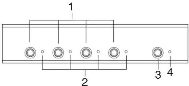
1 2 3 4VS0401 Front View
text_image
1 2 3 4| No. | Component Function | |
| 1 | P o r tPushbuttons | Pressing a port selection pushbutton routes the n VGA/Audio source from the corresponding input port to the output port for display. |
| 2 | Port LEDs There is one port | LED next to each port selection pushbutton. This lights green to indicate that the corresponding port has been selected.The connected port LED will flash when the front panel pushbuttons are manually locked. |
| 3 | Power Pushbutton Push this | button to turn on / off the switch. |
| 4 | Power LED | The LED (green) lights up when the switch is powered on.The LED (orange) lights up to indicate that the switch is in standby mode. |
VS0201 Rear View

text_image
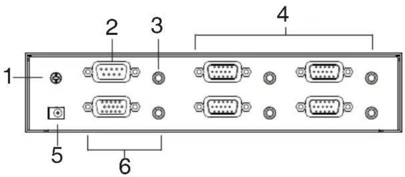
1 2 3 4 5 6VS0401 Rear View
text_image
1 2 3 4 5 6| No. | Component Function | |
| 1 | Grounding Terminal The grounding wire used to ground the unit attaches here. | |
| 2 | RS-232 Serial Port This is the serial remote port for input source selection and high-end system control. | |
| 3 | External IR Receiver Port | Connect the IR Receiver to this port. |
| 4 | Video / Audio Input Each input section is comprised of a VGA connector and a mini stereo audio jack. The cables that connect to the video and audio output ports on the computers/source devices plug in here. | |
| 5 | Power Jack The power adapter cable plugs in here. | |
| 6 | Video / Audio Output The cables that connect to the video and audio ports for the video display and audio output plug in here. |
This Page Is Intentionally Left Blank
Chapter 2
Hardware Setup

-
Important safety information regarding the placement of this device is provided on page 29. Please review it before proceeding.
-
Make sure that the power to all devices connected to the installation are turned off. You must unplug the power cords of any computers that have the Keyboard Power On function.
Installation
Installation of the VS0201 / VS0401 is simply a matter of plugging in the appropriate cables.
To install the switch, refer to the installation diagram on page 8 as you perform the following steps:
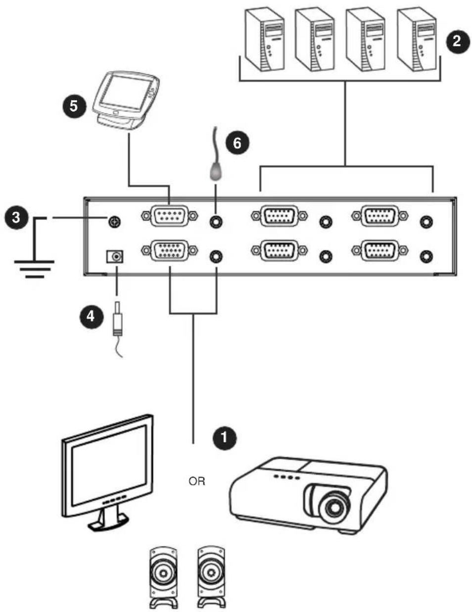
- Use a VGA/Audio cable to connect the VGA/Audio input of the video display and speaker devices to the VGA/Audio output ports on the rear of the VS0201 / VS0401.
- Use VGA/Audio cables to connect the VGA/Audio output ports on the source device(s) to the VGA/Audio input ports on the VS0201 / VS0401. Two/Four VGA/Audio input ports are located on the rear of the switch.
- Use a grounding wire to ground the unit by connecting one end of the wire to the grounding terminal, and the other end of the wire to a suitable grounded object.
- Plug the provided power adapter into an appropriate AC power source; plug the power adapter cable into the power jack on the VS0201 / VS0401.
- (Optional) To control the VS0201 / VS0401 system through the RS-232 port, connect the hardware/software controller here.
- (Optional) Connect the IR Receiver into the External IR Receiver Input Port.
The installation is complete, you may power on the display and source devices.
Installation Diagram
text_image
Diagram of a computer setup with labeled components including monitor, server rack, and projectorInstalling the RS-232 Controller
In order to use the RS-232 serial interface to attach a high-end controller (such as a PC) to the VS0201 / VS0401, use a RS-232 serial cable. The end connecting to the VS0201 / VS0401 should have a 9-pin male connector. Refer to step 5 on the diagram above.
Note: To configure the RS-232 serial port see page 11.
Overview
The VS0201 / VS0401 2/4-Port VGA Switch with Audio offers easy source device selection with either the front panel pushbuttons, IR remote control, or RS-232 serial interface. This chapter describes Source Selection, Power on Detection mode, Pushbutton Lock, Powering Off/Restarting, and the RS-232 serial port configuration and commands.
Note: Whenever the VS0201 / VS0401 is powered on, it automatically remembers the last connected port being used and connects to it. You may choose one of the methods outlined below to select a different port.
Manual Source Selection
To select the source device to view on your VGA display, press the front panel pushbutton that corresponds to the port it is connected to.
Note: The Port LED (green) light indicates which port is currently selected.
Remote Control Source Selection
First plug the External IR Receiver into the rear of the VS0201 / VS0401, place the receiver where the IR signal can be reached, and aim the remote at the External IR receiver.
To select a source device with the remote control, press the number button that corresponds to the port it is connected to, or cycle through the source devices by pushing the Port Up and Port Down buttons on the remote control unit, as such:
- Use the Port Up button to select the next port in ascending order (from left to right on the front view panel).
- Use the Port Down button to select the previous port in descending order (from right to left on the front view panel).
Pushbutton Lock
Pushbutton Lock allows you to secure your device by locking use of the front panel pushbuttons. To lock/unlock the front panel pushbuttons, do the following:
VS0201
Press and hold both 1 and 2 port selection pushbuttons for 5 seconds, then release.
VS0401
Press and hold both 1 and 4 port selection pushbuttons for 5 seconds, then release.
Note: 1. The front panel port LED will flash at one second intervals to indicate the pushbutton lock feature is enabled.
2. Repeat the steps above to unlock the front panel pushbuttons.
Powering Off and Restarting
If you power off the VS0201 / VS0401, follow these steps before powering it on again:
- Power off the attached devices.
- Unplug the power adapter cable from the VS0201 / VS0401.
- Wait 10 seconds, and then plug the power adapter cable back in.
- After the VS0201 / VS0401 is powered on, power on the attached devices.
RS-232 Serial Interface
The VS0201 / VS0401's built-in bi-directional RS-232 serial interface allows system control through a high-end controller, PC, and/or home automation / home theater software package.
Configuring the Serial Port
The controller's serial port should be configured as follows:
| Baud Rate 19200 | |
| Data Bits 8 | |
| Parity None | |
| Stop Bits 1 | |
| Flow Control None | |
The RS-232 control commands for Switch Port, Auto Switch, Power on Detection, Dynamic DDC, Pushbutton Lock, Read Firmware and Reset are found on the pages that follow.
Verification
In the steps below, after entering a command, a verification message appears at the end of the command line as follows:
- Command OK - indicates that the command is correct and successfully performed by the switch
- Command incorrect - indicates that the command has the wrong format and/or values.
Switch Port Command
The formulas for Switch Port commands are as follows:
- Switch Command + Input Command + Port Number [Enter]
For example, to switch the input port to port 02, type the following:
sw i02 [Enter]
- Switch Command + Control [Enter]
For example, to switch to the next port, type the following:
sw + [Enter]
The following tables show the possible values and formats for the Switch Port formulas:
| Command Description | |
| sw Switch command | |
| Input Command Description | |
| i Input command | |
| Port number Description | |
| xx 01-04 port (default is 01) | |
| Control Description | |
| + Switch to next port | |
| - Switch to previous port |
Note: 1. Each command string can be separated with a space.
- If the Port Number string is skipped, the default value is used.
The following table shows the available list of commands:
| Command | Input | Port | Control | Enter | Description |
| sw i | xx | [Enter] | Switch to | input port xx | |
| + | [Enter] | Switch to the next input | |||
| - | [Enter] | Switch to the previous input |
Switch Mode Command
You can choose how the VS0201 / VS0401 behaves when a new input source is connected. There are four switch modes:
Off mode: The switch behaves normally without the automatic switching operation.
Next mode: Switch priority is placed on the next port that has a new source device connected to it (default).
Priority mode: Places priority on a selected port so that when a source is connected to the port, the VS0201 / VS0401 automatically switches to it, and the port can not be changed until the source is unplugged or the mode is disabled.
POD mode: The Power On Detection (POD) mode enables the VS0201 / VS0401 to switch to the next port with a powered on source device when the current input source device is powered off. The POD mode works independent of the modes listed above.
The formulas for switch mode commands are as follows:
- Switch Mode Command + Input Command + Port Number + Control [Enter]
For example, to enable the Priority mode for port 02, type the following:
swmode i02 priority [Enter]
- Switch Mode Command + Control [Enter]
For example, to enable the Next mode, type the following:
swmode next [Enter]
- Switch Mode Command + Control [Enter]
For example, to enable the Off mode or to disable the Next/Priority mode, type the following:
swmode off [Enter]
- Switch Mode Command + Control [Enter]
For example, to enable the POD mode, type the following:
swmode pod on [Enter]
The following tables show the possible values and formats for the switch mode formulas:
| Command Description | |
| swmode Switch mode command | |
| Input Command Description | |
| i Input command | |
| Port number Description | |
| xx 01-04 port (default is 01) | |
| Control Description | |
| off No automatic switching operation | |
| next Priority is placed on the next port that has a new source connected to it (default) | |
| priority Priority is placed on a selected port | |
| POD On Switch to the next port with a powered on source device when the current input source is off | |
| POD Off Disable the POD mode |
The following table lists the available commands:
| Command | Input | Port # | Control | Enter | Description |
| swmode | off | [Enter] | Off mode enabled | ||
| next | [Enter] | Next mode enabled | |||
| i | xx | priority | [Enter] | Priority mode enabled for port number | |
| POD on | [Enter] | POD mode enabled | |||
| POD off | [Enter] | POD mode disabled |
Echo Command
If the Echo feature is enabled, each action from the front panel pushbuttons or IR remote control sends a corresponding acknowledgement message to the controller or management device connected to the RS-232 port.
The formula for the Echo command is as follows:
- Echo Command + Control [Enter]
For example, to enable the Echo function, type the following:
echo on [enter]
The following tables show the possible values and formats for the Control formulas:
| Command Description | |
| echo Echo | command |
| Control Description | |
| on Enable | Echo function |
| off Disable | Echo function (default) |
The following table lists the available commands:
| Command Control Enter Description | |||
| echo on [Enter] Echo function enabled | |||
Standby Command
The Standby command puts the device in a power saving mode. The action is the same as using the front panel or IR remote power button. When standby mode is on or off either of the three methods (RS-232, front panel, or remote control) can bring the device into or out off standby mode.
The formula for the Standby command is as follows:
- Standby Command + Control [Enter]
For example, to put the device in standby mode, type the following:
standby on [Enter]
The following tables show the possible values and formats for the Standby formulas:
| Command Description | |
| standby | Standby command |
| Control Description | |
| on Enable | Standby mode |
| off Disable | Standby mode (default) |
Note: Each command can be separated with a space.
The following table lists the available commands:
| Command C | Control Enter Description | ||
| standby on | [Enter] Standby mode enabled | ||
| off [Enter] Standby mode disabled (default) | |||
Dynamic DDC Command
The Dynamic DDC feature is used to monitor the connected display and provide the correct updated EDID information to the source device so that the display is optimized. With Dynamic DDC off, source devices do not receive updated EDID data which can cause display issues. If there is a problem with your display quality, it is recommended that Dynamic DDC be turned off.
The formula for the Dynamic DDC command is as follows:
- Dynamic DDC Command + Control [Enter]
For example, to turn on the Dynamic DDC feature, type the following:
ddc on [Enter]
The following tables show the possible values and formats for the Dynamic DDC formulas:
| Command Description | |
| ddc Dynamic DDC command | |
| Control Description | |
| on Enable Dynamic DDC | |
| off Disable Dynamic DDC (default) |
Note: Each command can be separated with a space.
The following table lists the available commands:
| Command Control Enter Description | |||
| ddc on [Enter] Dynamic DDS enabled | |||
Pushbutton Lock Command
The Pushbutton Lock feature allows you to secure your device by locking use of the front panel pushbuttons.
The formula for the Pushbutton Lock command is as follows:
- Pushbutton Lock Command + Control [Enter]
For example, to disable use of the front panel pushbuttons, type the following:
button off [Enter]
The following tables show the possible values and formats for the Control command:
| Command Description | |
| button Push button Lock command | |
| Control Description | |
| on Enable | front panel pushbuttons (default) |
| off Disable | front panel pushbuttons:Source port LED flashes every 1 second to indicate pushbuttons are locked |
Note: Each command can be separated with a space.
The following table lists the available commands:
| Command | Control Enter | Description | |
| button on | [Enter] Front panel pushbuttons enabled (default) | ||
| off [Enter] Front panel pushbuttons disabled | |||
Read Firmware Command
The Read Firmware feature allows you to read the firmware information of the VS0201 / VS0401.
The formula for the Read Firmware command is as follows:
- Read Firmware Command + Control [Enter]
For example, to display the firmware information, type the following:
read version [Enter]
The following tables show the possible values and formats for the Read Firmware formulas:
| Command Description | |
| read Read | Firmware command |
| Control Description | |
| version Read | device firmware version |
Note: Each command can be separated with a space.
The following table lists the available commands:
| Command | Control Enter | Description | |
| read version | [Enter] Read device firmware version | ||
Reset Command
The Reset feature resets the device back to the factory default settings. The reset function does not effect the on/off power status of the device.
The formula for the Rest commands is as follows:
- Reset Command [Enter]
For example, to reset back to the factory default settings, type the following: reset [Enter]
The following table shows the value for the formula:
| Command Description | |
| reset Reset command |
Note: Each command can be separated with a space.
The following table lists the available commands:
| Command Enter Description | |
| reset [Enter] Reset the device back to the factory default settings | |
Baud Rate Command
You can select the RS-232 Baud Rate you want the VS0201 / VS0401 to use. Options are 9600, 19200 (default), and 38400.
The formula for the Baud Rate command is as follows:
- Baud Rate Command + Control [Enter]
For example, to select 38400 as your baud rate, type the following:
baud 38400 [enter]
The following tables show the possible values and formats for the Baud Rate formulas:
| Command Description | |
| baud Baud | Rate command |
| Control Description | |
| 9600 Use | 9600 baud rate |
| 19200 Use | 19200 baud rate (default) |
| 38400 Use | 38400 baud rate |
The following table lists the available commands:
| Command Control Enter Description | |||
| baud 9600 | [Enter] Sets the baud rate to | 9600 | |
| 19200 [Enter] Sets the baud rate to | 19200 | ||
| 38400 [Enter] Sets the baud rate to | 38400 | ||
This Page Intentionally Left Blank
The Firmware Upgrade Utility
Introduction
The purpose of the Windows-based Firmware Upgrade Utility is to provide an easy process for upgrading the VS0201 / VS0401. The program comes as part of a Firmware Upgrade Package that is specific for each device.
As new firmware versions become available, new firmware upgrade packages are posted on our website. Check the website regularly to find the latest information and packages.
Downloading the Firmware Upgrade Package
To download the firmware upgrade package:
-
On our Website go to: Download - Firmware and choose the device model, or from the VS0201 / VS0401 product page under the Resources tab, select Firmware. A list of available firmware upgrade packages appears.
-
Choose the firmware upgrade package that you wish to install (usually the most recent) and download it to your computer.
Preparation
To prepare for the firmware upgrade, do the following:
- Use an RS-232 cable to connect a COM port on your computer to the RS-232 Serial Port of your VS0201 / VS0401.

flowchart
graph TD
    A["Server"] -->|Data Flow Left| B["Internal VGA"]
    B --> C["I/O Terminal"]
    C --> D["Internal I/O Port"]
    D --> E["External I/O Terminal"]
    style A fill:#f9f,stroke:#333
    style B fill:#ccf,stroke:#333
    style C fill:#cfc,stroke:#333
    style D fill:#fcc,stroke:#333
-
Unplug the VS0201 / VS0401's power adapter.
-
Hold-down front panel pushbutton 1 and plug the power adapter into the VS0201 / VS0401 to power the unit.
-
If successful,
- The VS0201 / VS0401's port 1 and port 2 LEDs will start flashing and you can start the upgrade process as explained on the next page.
Starting the Upgrade
To upgrade the firmware:
- Run the downloaded firmware upgrade package file either by double-clicking the file icon, or by opening a command line and entering the full path to it.
The Firmware Upgrade Utility welcome screen appears:
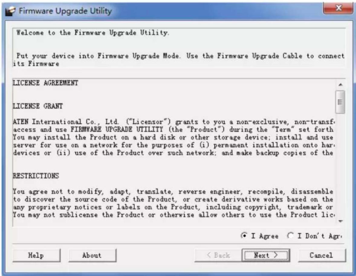
text_image
Welcome to the Firmware Upgrade Utility. Put your device into Firmware Upgrade Mode. Use the Firmware Upgrade Cable to connect its Firmware LICENSE AGREEMENT LICENSE GRANT ATEN International Co., Ltd. ("Licensor") grants to you a non-exclusive, non-transf access and use FIRMWARE UPGRADE UTILITY (the "Product") during the "Term" set forth You may install the Product on a hard disk or other storage device; install and use server for use on a network for the purposes of (i) permanent installation onto hard devices or (ii) use of the Product over such network; and make backup copies of the RESTRICTIONS You agree not to modify, adapt, translate, reverse engineer, recompile, disassemble to discover the source code of the Product, or create derivative works based on the any proprietary notices or labels on the Product, including copyright, trademark or You may not sublicense the Product or otherwise allow others to use the Product lic. ● I Agree ○ I Don't Agr. Help About < Back Next > CancelNote: The screens shown in this section are for reference only. The wording and layout of the actual screens put up by the Firmware Upgrade Utility may vary slightly from these examples.
- Read and Agree to the License Agreement (click the I Agree radio button).
(Continues on next page.)
(Continued from previous page.)
- Click Next to continue. The Firmware Upgrade Utility main screen appears. The devices capable of being upgraded are listed in the Device List panel:
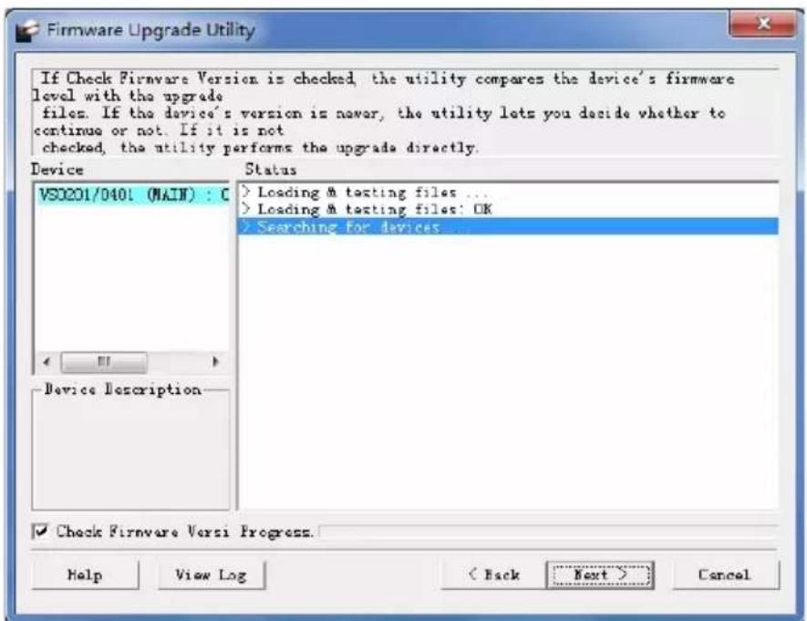
text_image
If Check Firmware Version is checked, the utility compares the device's firmware level with the upgrade files. If the device's version is never, the utility lets you decide whether to continue or not. If it is not checked, the utility performs the upgrade directly. Device Status VS0201/0401 (MAIN) : C > Loading & testing files ... > Loading & testing files: OK > Searching for devices ... Device Description ✓ Check Firmware Versi Progress. Help View Log < Back Next > Cancel- Click Next to perform the upgrade. The port 1 and port 2 LEDs will flash while the upgrade is in process.
If you enabled Check Firmware Version, the Utility compares the device's firmware level with that of the upgrade files. If it finds that the device's version is higher than the upgrade version, it brings up a dialog box informing you of the situation and gives you the option to continue or cancel.

text_image
Warning The firmware (Ver 1.1.102) is not newer than current firmware (Ver 1.1.102) in device VS0201/0401 (MAIN) : 000 Continue the upgrade? (Yes/No) 是(Y) 否(N)If you didn't enable Check Firmware Version, the Utility installs the upgrade files without checking whether they are a higher level, or not.
Status messages appear in the Status Messages panel, and the progress toward completion is shown on the Progress bar.
Upgrade Succeeded
After the upgrade has completed, all port LEDs will stop flashing and a screen appears to inform you that the procedure was successful:
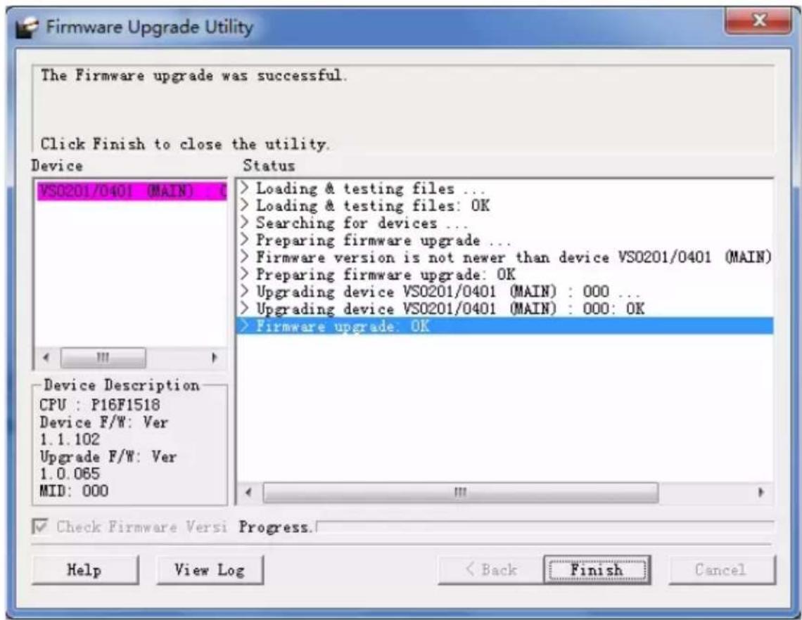
text_image
Firmware Upgrade Utility The Firmware upgrade was successful. Click Finish to close the utility. Device VS0201/0401 (MAIN) ( Status > Loading & testing files ... > Loading & testing files: OK > Searching for devices ... > Preparing firmware upgrade ... > Firmware version is not newer than device VS0201/0401 (MAIN) > Preparing firmware upgrade: OK > Upgrading device VS0201/0401 (MAIN) : 000 ... > Upgrading device VS0201/0401 (MAIN) : 000: OK > Firmware upgrade: OK Device Description CPU : P16F1518 Device F/W: Ver 1.1.102 Upgrade F/W: Ver 1.0.065 MID: 000 Check Firmware Versi Progress. Help View Log Back Finish CancelClick Finish to close the Firmware Upgrade Utility.
Upgrade Failed
If the Upgrade Succeeded screen doesn't appear, it means that the upgrade failed to complete successfully. See the next section, Firmware Upgrade Recovery, for how to proceed.
Firmware Upgrade Recovery
There are three conditions that call for firmware upgrade recovery:
- When a firmware upgrade is manually aborted.
- When the mainboard firmware upgrade fails.
- When the I/O firmware upgrade fails.
To perform a firmware upgrade recovery, do the following:
- Power off the device.
- Connect the RS-232 cable to the RS-232 Serial Port.
- Repeat the upgrade procedure.
Safety Instructions
General
- This product is for indoor use only.
- Read all of these instructions. Save them for future reference.
◆ Follow all warnings and instructions marked on the device. - Do not place the device on any unstable surface (cart, stand, table, etc.). If the device falls, serious damage will result.
- Do not use the device near water.
- Do not place the device near, or over, radiators or heat registers.
- The device cabinet is provided with slots and openings to allow for adequate ventilation. To ensure reliable operation, and to protect against overheating, these openings must never be blocked or covered.
- The device should never be placed on a soft surface (bed, sofa, rug, etc.) as this will block its ventilation openings. Likewise, the device should not be placed in a built-in enclosure unless adequate ventilation has been provided.
- Never spill liquid of any kind on the device.
- Unplug the device from the wall outlet before cleaning. Do not use liquid or aerosol cleaners. Use a damp cloth for cleaning.
- The device should be operated from the type of power source indicated on the marking label. If you are not sure of the type of power available, consult your dealer or local power company.
- The device is designed for IT power distribution systems with 230V phase-to-phase voltage.
- To prevent damage to your installation it is important that all devices are properly grounded.
- The device is equipped with a 3-wire grounding type plug. This is a safety feature. If you are unable to insert the plug into the outlet, contact your electrician to replace your obsolete outlet. Do not attempt to defeat the purpose of the grounding-type plug. Always follow your local/national wiring codes.
-
Do not allow anything to rest on the power cord or cables. Route the power cord and cables so that they cannot be stepped on or tripped over.
-
If an extension cord is used with this device make sure that the total of the ampere ratings of all products used on this cord does not exceed the extension cord ampere rating. Make sure that the total of all products plugged into the wall outlet does not exceed 15 amperes.
- To help protect your system from sudden, transient increases and decreases in electrical power, use a surge suppressor, line conditioner, or un-interruptible power supply (UPS).
- Position system cables and power cables carefully; Be sure that nothing rests on any cables.
- Never push objects of any kind into or through cabinet slots. They may touch dangerous voltage points or short out parts resulting in a risk of fire or electrical shock.
- Do not attempt to service the device yourself. Refer all servicing to qualified service personnel.
- If the following conditions occur, unplug the device from the wall outlet and bring it to qualified service personnel for repair.
◆ The power cord or plug has become damaged or frayed.
- Liquid has been spilled into the device.
◆ The device has been exposed to rain or water.
- The device has been dropped, or the cabinet has been damaged.
- The device exhibits a distinct change in performance, indicating a need for service.
- The device does not operate normally when the operating instructions are followed.
- Only adjust those controls that are covered in the operating instructions. Improper adjustment of other controls may result in damage that will require extensive work by a qualified technician to repair.
Technical Support
International
- For online technical support – including troubleshooting, documentation, and software updates: http://support.aten.com
- For telephone support, Telephone Support, page iii
North America
| Email Support support@aten-usa.com | ||
| Online Technical Support | Troubleshooting Documentation Software Updates | http://www.aten-usa.com/support |
| Telephone Support 1-888-999-ATEN | ext 4988 | |
When you contact us, please have the following information ready beforehand:
- Product model number, serial number, and date of purchase.
- Your computer configuration, including operating system, revision level, expansion cards, and software.
- Any error messages displayed at the time the error occurred.
- The sequence of operations that led up to the error.
◆ Any other information you feel may be of help.
Specifications
| Function VS0201 VS0401 | ||||
| Display Connections 2 4 | ||||
| Connectors Input Video 2 x H | DB-15 Male (Blue) 4 x HDB-15 Male (Blue) | |||
| Audio 2 x Mini Stereo Jack Female (Green) | 4 x Mini Stereo Jack Female (Green) | |||
| Output Video 1 x HDB-15 Female (Blue) | 1 x HDB-15 Female (Blue) | |||
| Audio 1 x Mini Stereo Jack Female (Green) | 1 x Mini Stereo Jack Female (Green) | |||
| RS-232 Port 1 x DB-9 Female (Black) | ||||
| IR Input port 1 x Mini Stereo Jack Female (Black) | ||||
| Power 1 x DC Jack | ||||
| Switches | Port Selection 2 x Pushbuttons | 4 x Pushbuttons | ||
| Power | 1 x Pushbutton | |||
| LEDs | Selected | 2 x (Green) | 4 x (Green) | |
| Power | 1 x (Green / Orange) | |||
| Video | 1920x1440 @ 30 m1280x1024 @ 65 m | |||
| Power Consumption | DC5.3V, 0.6W | |||
| Environment Operating Temp. | 0–50°C | |||
| Storage Temp | -20–60°C | |||
| Humidity | 0–80% RH, Non-condensing | |||
| Physical Properties | Housing | Metal | ||
| Weight | 0.45kg | 0.66kg | ||
| Dimensions(L x W x H) | 13 x 7.61 x 4.2 cm | 20 x 7.61 x 4.2 cm | ||
Limited Warranty
ATEN warrants its hardware in the country of purchase against flaws in materials and workmanship for a Warranty Period of two [2] years (warranty period may vary in certain regions/countries) commencing on the date of original purchase. This warranty period includes the LCD panel of ATEN LCD KVM switches. Select products are warranted for an additional year (see A+ Warranty for further details). Cables and accessories are not covered by the Standard Warranty.
What is covered by the Limited Hardware Warranty
ATEN will provide a repair service, without charge, during the Warranty Period. If a product is detective, ATEN will, at its discretion, have the option to (1) repair said product with new or repaired components, or (2) replace the entire product with an identical product or with a similar product which fulfills the same function as the defective product. Replaced products assume the warranty of the original product for the remaining period or a period of 90 days, whichever is longer. When the products or components are replaced, the replacing articles shall become customer property and the replaced articles shall become the property of ATEN.
To learn more about our warranty policies, please visit our website: http://www.aten.com/global/en/legal/policies/warranty-policy/
This Page Intentionally Left Blank