TiX870 - Thermography FLUKE - Free user manual and instructions
Find the device manual for free TiX870 FLUKE in PDF.

User questions about TiX870 FLUKE
0 question about this device. Answer the ones you know or ask your own.
Ask a new question about this device
Download the instructions for your Thermography in PDF format for free! Find your manual TiX870 - FLUKE and take your electronic device back in hand. On this page are published all the documents necessary for the use of your device. TiX870 by FLUKE.
USER MANUAL TiX870 FLUKE
Each Fluke product is warranted to be free from defects in material and workmanship under normal use and service. The warranty period is 2 years and begins on the date of shipment. Parts, product repairs, and services are warranted for 90 days. This warranty extends only to the original buyer or end-user customer of a Fluke authorized reseller, and does not apply to fuses, disposable batteries, or to any product which, in Fluke's opinion, has been misused, altered, neglected, contaminated, or damaged by accident or abnormal conditions of operation or handling. Fluke warrants that software will operate substantially in accordance with its functional specifications for 90 days and that it has been properly recorded on non-defective media. Fluke does not warrant that software will be error free or operate without interruption.
Fluke authorized resellers shall extend this warranty on new and unused products to end-user customers only but have no authority to extend a greater or different warranty on behalf of Fluke. Warranty support is available only if product is purchased through a Fluke authorized sales outlet or Buyer has paid the applicable international price. Fluke reserves the right to invoice Buyer for importation costs of repair/replacement parts when product purchased in one country is submitted for repair in another country. Fluke's warranty obligation is limited, at Fluke's option, to refund of the purchase price, free of charge repair, or replacement of a defective product which is returned to a Fluke authorized service center within the warranty period.
To obtain warranty service, contact your nearest Fluke authorized service center to obtain return authorization information, then send the product to that service center, with a description of the difficulty, postage and insurance prepaid (FOB Destination). Fluke assumes no risk for damage in transit. Following warranty repair, the product will be returned to Buyer, transportation prepaid (FOB Destination). If Fluke determines that failure was caused by neglect, misuse, contamination, alteration, accident, or abnormal condition of operation or handling, including overvoltage failures caused by use outside the product's specified rating, or normal wear and tear of mechanical components, Fluke will provide an estimate of repair costs and obtain authorization before commencing the work. Following repair, the product will be returned to the Buyer transportation prepaid and the Buyer will be billed for the repair and return transportation charges (FOB Shipping Point).
THIS WARRANTY IS BUYER'S SOLE AND EXCLUSIVE REMEDY AND IS IN LIEU OF ALL OTHER WARRANTIES, EXPRESS OR IMPLIED, INCLUDING BUT NOT LIMITED TO ANY IMPLIED WARRANTY OF MERCHANTABILITY OR FITNESS FOR A PARTICULAR PURPOSE. FLUKE SHALL NOT BE LIABLE FOR ANY SPECIAL, INDIRECT, INCIDENTAL, OR CONSEQUENTIAL DAMAGES OR LOSSES, INCLUDING LOSS OF DATA, ARISING FROM ANY CAUSE OR THEORY.
Since some countries or states do not allow limitation of the term of an implied warranty, or exclusion or limitation of incidental or consequential damages, the limitations and exclusions of this warranty may not apply to every buyer. If any provision of this Warranty is held invalid or unenforceable by a court or other decision-maker of competent jurisdiction, such holding will not affect the validity or enforceability of any other provision.
11/99
Fluke Corporation
P.O. Box 9090
Everett, WA 98206-9090
U.S.A.
Table of Contents
Title Page
Introduction ...... 1
Product Overview ....1
How to Contact Fluke....1
Safety Information....2
Product Familiarization ....2
Standard Packaging....2
Features......4
Components and Controls 4
Connection and Power Supply ....7
Rotatable Lens....8
Touch Screen....9
Main Display Area....10
Shortcut Menu Area....12
On-Screen Display....14
Non Uniformity Correction (NUC) 14
Basic Operation 20
Turn On and Off the Imager 20
Focus 21
Capture and Save Images 21
Digital Zoom....21
System Menu....22
Capture Mode 26
Single-capture 26
Frame Interval....26
Timer....27
Measurement Settings....28
Emissivity....29
Reflected Temperature 30
Environment Temperature....30
Humidity....31
Distance....31
Transmittance 32
Base Temperature 32
View Mode....33
PIP Mode....33
Measuring Tools....35
To add a ROI 36
ROI Operation 38
Temperature Difference Calculation....41
Audible Alarm....42
Non-Radiometric Videos....43
Settings....44
Regional Intelligent Temperature Span Adjustment....47
TWB Technology....47
TFocus Technology....49
Thermal Image/Video Analysis....50
Thermal Image....51
Picture-in-Picture (PIP) 53
Fully-Radiometric Videos....53
Automatically Name Scanned Files ....54
Add an Annotation ....54
Voice Annotation....54
Text Remark ....55
Tag....55
SmartView™ IR Software....56
Download and Install the SmartView IR Software....56
Real-time View and Record Fully-Radiometric Video Streaming 57
Import and Save Thermal Image Files....58
Accessories....59
Optional Lenses 60
Maintenance 61
Clean the Product 61
Lens Care 61
Battery Care....62
Charge the Battery....62
Product Disposal....63
Radio Frequency....63
Specifications....64
Introduction
Product Overview
The TiX800/TiX1000 Series Thermal Imagers (the "Product" or "Imager") are diagnostic infrared imaging cameras for use in many applications including equipment troubleshooting, diagnosis, preventive and predictive maintenance, building diagnosis and energy efficiency assessment, and product development or scientific research in various industries.
The Imager displays thermal images on a high-visibility, industrial-quality OLED touch screen. The Imager can save images to internal memory or to a removable SD memory card. You can transfer the images and data stored in internal memory, or on the memory card, to a PC using the Type-C USB 2.0 high-speed interface on the Imager and the USB port on a PC. You can transfer fully-radiometric videos to a monitor, TV or other video display devices in real time with an HDMI interface.
The Imager includes a professional thermal image analysis software – SmartView™ IR. The SmartView IR is a high-performance, professional thermal image analysis software for thermal image analysis, fully-radiometric video analysis and professional thermal image reporting.
The Imagers are powered by smart rechargeable lithium-ion batteries.
How to Contact Fluke
Fluke Corporation operates worldwide. For local contact information, go to our website: cn.fluke.com (Chinese) or www.fluke.com (English)
To register your product, view, print, or download the latest manual or manual supplement, go to our website.
Fluke Corporation
P.O. Box 9090
Everett, WA 98206-9090
+1-425-446-5500
fluke-info@fluke.com
Safety Information
General Safety Information is in the printed Safety Information document that ships with the Product and at www.fluke.com. More specific safety information is listed where applicable.
A Warning identifies conditions and procedures that are dangerous to the user. A Caution identifies conditions and procedures that can cause damage to the Product or the equipment under test.
Caution
Storage and/or continuously operating of the Imager in extreme ambient temperature may result in temporary interruption of operation. In this case, let the Imager stabilize (cool down or warm up) before you resume operation.
Product Familiarization
The manual explains functions and features for multiple models. Since different models have different functions and features, not all of the information in the manual applies to your Imager.
Standard Packaging
To prevent damage during shipment, the Product is shipped in a specially designed package. Check the Product carefully and inform the carrier of any damage.
When unpacking the Product, check the standard accessories listed in Table 1 and other ordered parts listed on the packing list. If there is any shortage of parts, notify the nearest Fluke Technical Service Center or the Service Center located in the place of purchase.
Figure 1 and Table 1 list the standard accessories for the Product. See Accessories for optional accessories.

Figure 1. Standard Accessories
Table 1. Standard Accessories
| No. Description Quantity | ||
| 1 | Hand strap 1 | |
| 2 | The Thermal Imager | 1 |
| 3 | Standard lens (installed) | 1 |
| 4 | Lens cover (removable) | 1 |
| 5 | Neck strap | 1 |
| 6 | USB-SD reader | 1 |
| 7 | AC adapter | 1 |
| 8 | 2-bay battery charging base | 1 |
| 9 | Rechargeable Li-ion battery, BP1000 | 3 |
| 10 | Included documentation, including a Safety Information, a Quick Reference Guide, a Quality Certificate, and a Warranty Card | 1 |
| Not shown | Type-C USB cable, 1 m 1 | |
| HDMI video cable, 1 m 1 | ||
| High-speed SD card, 128 GB 1 | ||
| Hard carrying case 1 | ||
Features
This section describes each component of the Product and the display. Please read this section carefully before use.
Components and Controls
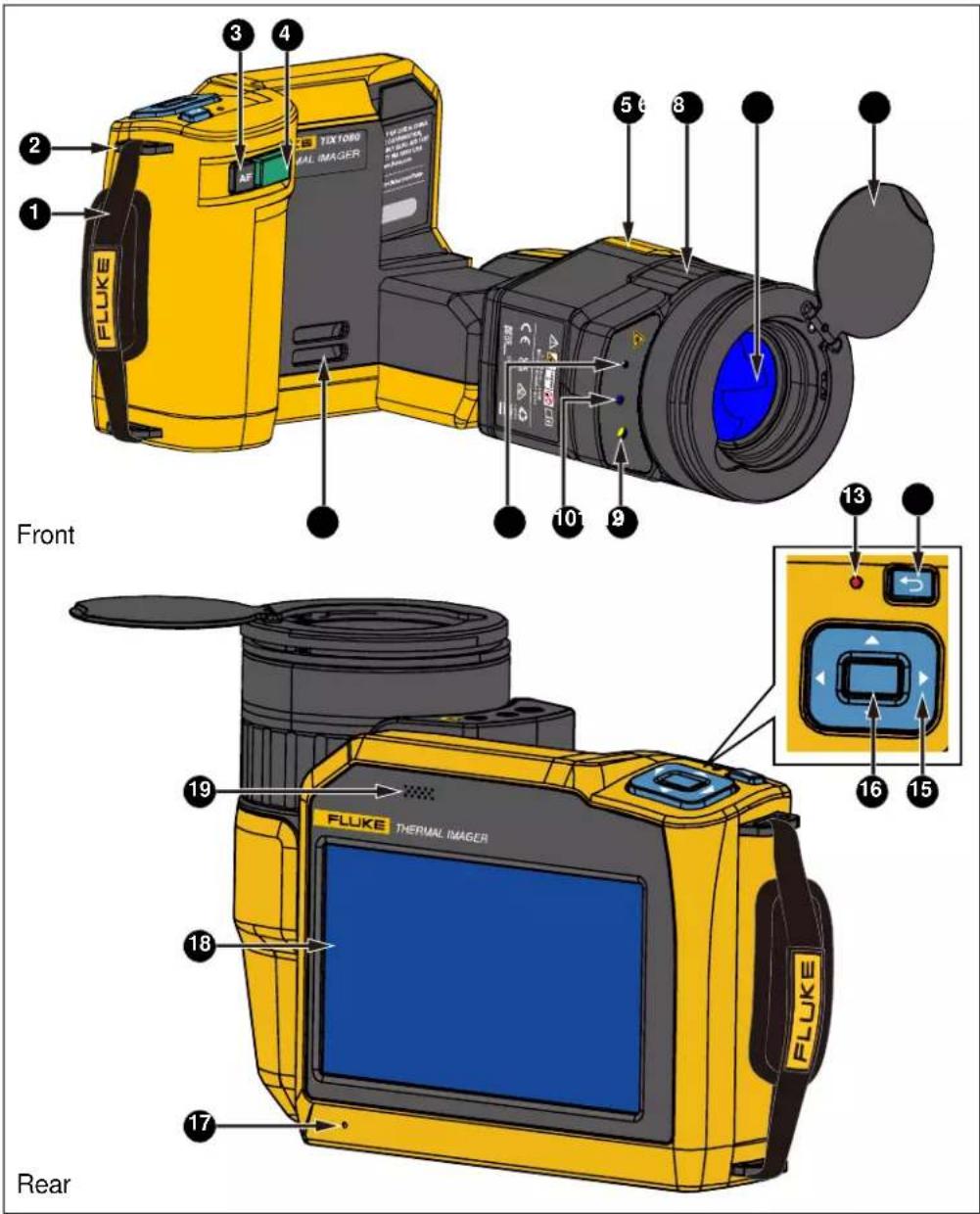
For the components and controls of the Imager, see Figure 2. Table 2 lists the features and functions of each component.
text_image
FLUKE TIX TORS MAL IMAGER 2 3 4 5 6 8 10 9 Front 13 16 15 FLUKE THERMAL IMAGER 19 18 17 RearFigure 2. Components and Controls
Table 2. Components and Controls
| No. | Item Description | |
| 1 | Hand strap | Makes the Product easy to carry and comfortable to use. |
| 2 | Hand strap anchor | Use the anchor to secure the hand strap provided with the Product. The hand strap can improve handheld stability and comfort. |
| 3 |  AF (Auto Focus)button AF (Auto Focus)button | For live image screen, push AF, the Imager will automatically focus and show a clear thermal image. SeeFocus. |
| 4 |   apture button apture button   | The function of the button depends on the capture mode:Single-frame mode:In the live image screen, pushonce to freeze the screen.In the image freeze screen, pushonce again to save the thermal image to the specified storage medium (seeSettings).Frame Interval mode:In the live image screen, pushonce to start the recording of video at the frame rate you have set.During recording a fully-radiometric video, pushonce again to stop recording and freeze the screen. You can play back the video.Pushonce again or tapSaveon the screen to save the video in the cache to the specified storage medium.In Timer mode:Pushonce to start the recording of the fully-radiometric video. Video frames are recorded to the timer you set.Pushonce again to stop the recording and freeze the screen. You can play back the video.Pushonce again or tapSaveon the screen, to save the video in the cache to the specified storage medium (seeSettings). |
| 5 | Rotatable lens Component Component | 180° rotatable lens. SeeRotatable Lens. |
| 6 |  Manual focus control Manual focus control  ed lens ed lens | The focus control can be manually rotated clockwise or counterclockwise to adjust the imaging clarity. |
| 7 |  lens lens lens cover Retractable lens cover Retractable  | Replaceable infrared lens assembly with standard lens. SeeAccessoriesfor details. |
| 8 | LED torch/flashlight | Lens cover. |
| 9 | Use to identify the target in dark environment. | |
| 10 | Visual light camera lens | 5 mega pixels |
| 11 | Laser pointer Use to quickly aim at the target under test. | |
| 12 | Neck strap anchor | Use the anchor to secure the neck strap provided with the Product. |
| 13 | Power indicator [A267] | The power indicator goes off during normal operation.The power indicator shows yellow-green during sleep/shutdown process for reboot. |
| 14 | Power/Back button  | Power button- Push and hold for 2 s to turn on the Product, turn off the Product,reboot the Product, or put the Product in Sleep mode according toon-screen prompt.- In Sleep mode, push to wake up the Product.- In screen-off mode, briefly push to wake up the screen.Back buttonReturn to previous menu. In image freeze interface, push to returnto live image screen.Depending on the screen, has the same function as or on the screen (in some cases, Back may need to be pressed twice).This button is invalid on video recording screen. |
| 15 | Navigation keys 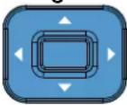 | Push the arrow keys to move the cursor on the screen. |
| 16 | OK button | Push OK (the middle of the navigation arrow keys) to select the optionwhere the cursor is located.- On the System Menu screen, push OK to bring up the correspondingsub-menu or activate the currently selected function.- On the Home screen, push OK to bring up System Menus (samefunction as ...). SeeSystem Menufor more information.- On the Gallery screen, push OK to bring up the functions associatedwith the image where the cursor is located, includingAnalyze File(Playwhen a video is selected),File PropertiesandDelete.SeeGalleryfor more information.This button is invalid on video recording screen. |
| 17 | Microphone | Used to record a voice annotation. |
| 18 | OLED touchscreen Touchscreen | |
| 19 | Speaker | Used to play back audio files or voice annotations, and to sound alarmsfor high/low temperature over-limit. |
Connection and Power Supply
Figure 3 shows the bottom of the Imager. Table 3 lists the features and functions of each component on the bottom panel.
text_image
Diagram of a yellow handheld device with labeled components including ports and connectorsFigure 3. Bottom of The Product
Table 3. Bottom of The Product
| No. | Item Description | |
| 1 | Interface protective cover | |
| 2 | HDMI interface Mini HDMI interface | |
| 3 | Type-C USB interface Type-C USB 2.0 interface | |
| 4 | Battery compartment cover | |
| 5 | SD card slot Standard SD card slot | |
| 6 | Tripod mount | Tripod standard threaded hole, UNC 1/4"-20 mounting thread. |
Rotatable Lens
The Imager features a 180^ rotatable lens to capture images at any angle.
See Figure 4 for how to adjust the lens.

natural_image
Diagram of a yellow and gray mechanical device with red arrows indicating rotational or directional motion (no text or symbols)Figure 4. 180° Rotatable Lens
Note
Adjust the view to suit your working posture.
Touch Screen
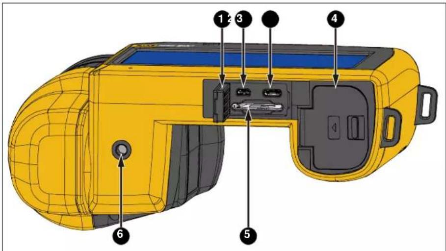
The screen is divided into: the Main Display Area in the middle, the Shortcut Menu Area containing touch buttons on the left and right sides, and the System Menu Area superimposed on the bottom of the Main Display Area, as shown in Figure 5.
text_image
1 2 3 1 Max 34.3°C Min 24.9°C Avg 25.8°C BT 100% 34.3°C NUC 13:09:11 2022-07-26 0.95 20.0°C 20.0°C 50% 1.0m 1.00 24.9° 4Figure 5. Screen
Table 4. Screen
| No. Item Description | ||
| 1 | Shortcut Menu Area | Shortcuts to the most used settings for changing parameters or selecting functions and options. |
| 2 | On-Screen Display | See System Menu. |
| 3 | Main Display Area | Shows videos/images. In addition, current measurements, environmental data and equipment status show as On-Screen Display. The Main Display Area displays different content depending on the current operating mode and screen, as detailed in the relevant sections below. |
| 4 | System Menu Area | Shows when you tap system menu button, a system menu shows depending on the operating environment. For more information, see System Menu. |
Main Display Area

text_image
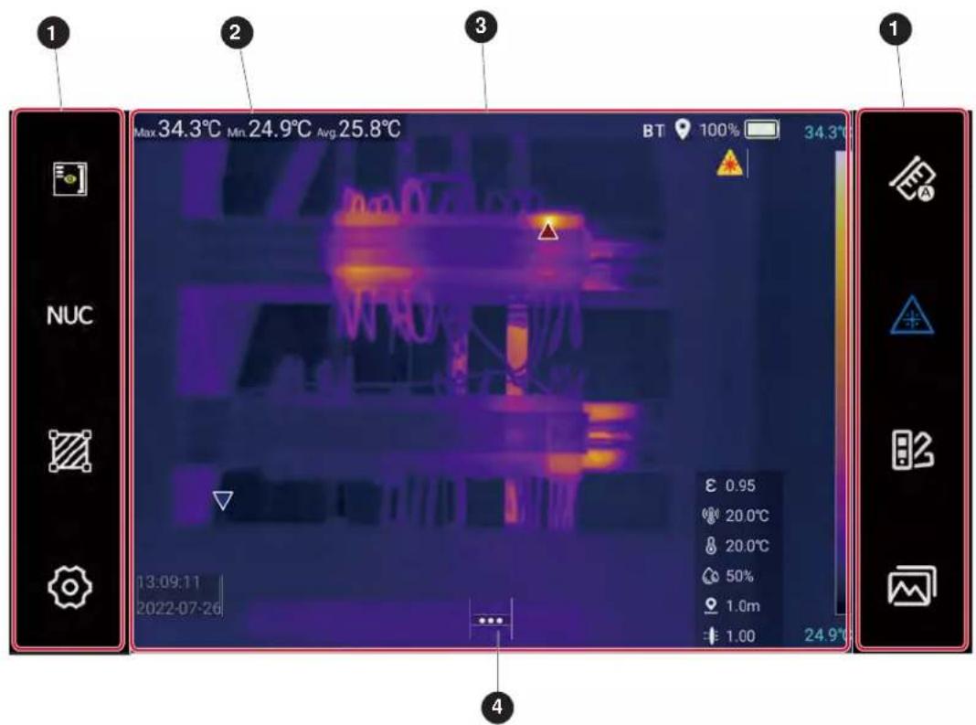
1 Max:34.3°C Min:24.9°C Avg:25.8°C BT 100% 34.3°C SR 7 8 9 10 11 13:09:11 2022-07-26 17 14 24.9°C 0.95 20.0°C 20.0°C 50% 1.0m 1.00 12Figure 6. On-Screen Display
Note
Not all information is always shown on screen, to customize the information that shows, see Settings.
Table 5. On-Screen Display
| No. Description | |
| 1 | On-Screen DisplayThe global maximum (Max), minimum (Min) and average (Avg) temperatures as well as point,line and area temperatures for measurement and analysis are displayed based on systemsettings. |
| 2 | Bluetooth IndicatorBluetooth status. When enabled, if a Bluetooth headset is connected, the Bluetooth headseticon (with a Bluetooth symbol in the middle of the headset) shows. |
| 3 | GPS IndicatorGPS status. See Settings for details. |
| 4 | Battery PercentageSee Battery Care and Charge the Battery for details on batteries. |
| 5 | Battery IndicatorShows the remaining battery power (the icon is red when the power is lower than 20%). See Battery Care and Charge the Battery for details on batteries. |
| 6 | Upper Temperature Limit of Color BandThe highest temperature shown on the color band. See Settings for details. |
| 7 | Super-Resolution IndicatorSuper-resolution function status |
| 8 | Laser Pointer IndicatorLaser pointer status |
| 9 | HDMI IndicatorHDMI interface status |
| 10 | Digital Camera IndicatorDigital camera status |
| 11 | Temperature Span of Color BandColor band representation (shows the relationship between temperature and color) |
| 12 | Lower Temperature Limit of Color BandThe lowest temperature shown on the color band. |
| 13 | Temperature Measuring ParametersRelevant temperature measuring parameters are shown. See Measurement Settings for details. |
| 14 | Location of the Maximum Temperature PointLocation of the maximum temperature point on full screen (a triangle cursor in red) |
| 15 | System Menu ButtonsOpen the System Menu, where you can set capture mode, view mode, measurement settings, alarms, and system settings.See System Menu for more information on system settings. |
| 16 | Location of the Minimum Temperature PointLocation of the minimum temperature point on full screen (an inverted triangle cursor in blue). |
| 17 | Time and DateCurrent clock date and time |
Shortcut Menu Area
Use the Touch keys in the Shortcut Menu Area to change parameters or select functions and options. Figure 7 and Table 6 the features and functions of each component of the Shortcut Menu Area.

text_image
Max 34.3°C Min 24.9°C Avg 25.8°C BT 100% 34.3°C ① ② ③ ④ ⑤ ⑥ ⑦ ⑧ ⑨Figure 7. Shortcut Menu Area
Table 6. Touch Key Functions
| No. Description | |
| 1 | [STWS]On-Screen DisplayShow or hide the on-screen display.See Figure 6 and Table 5 for details. |
| 2 |  Non Uniformity Correction (NUC)Tap NUC icon to execute the Non Uniformity Correction function. See Non Uniformity Correction (NUC) for details. Non Uniformity Correction (NUC)Tap NUC icon to execute the Non Uniformity Correction function. See Non Uniformity Correction (NUC) for details. |
| 3 |  Measuring ToolsThe Imager comes with measuring and analysis tools. See Measuring Tools for details. Measuring ToolsThe Imager comes with measuring and analysis tools. See Measuring Tools for details. |
| 4 |  System SettingsTap to enter the System Settings interface. For more information, see Settings. System SettingsTap to enter the System Settings interface. For more information, see Settings. |
| 5 |  Temperature Span ModeSwitches between Auto Span and Manual Span modes.For more information, see Temperature Span Mode. Temperature Span ModeSwitches between Auto Span and Manual Span modes.For more information, see Temperature Span Mode. |
| 6 |  Laser PointerTap and hold to turn on the Laser Pointer and release the icon to turn off the Laser Pointer. For more information, see Laser Pointer. Laser PointerTap and hold to turn on the Laser Pointer and release the icon to turn off the Laser Pointer. For more information, see Laser Pointer. |
| 7 |  Color PalettesTap to enter the submenu for quickly switching palettes, you can choose palettes, and set color alarms (isotherm).For more information, see Color Palettes. Color PalettesTap to enter the submenu for quickly switching palettes, you can choose palettes, and set color alarms (isotherm).For more information, see Color Palettes. |
| 8 |  GalleryTap to enter the Gallery to browse or analyze thermal images or fully-radiometric videos.For more information, see Gallery. GalleryTap to enter the Gallery to browse or analyze thermal images or fully-radiometric videos.For more information, see Gallery. |
| 9 |  System Menu KeysOn the System Menu Area, you can set up the capture mode, measurement settings, view mode, temperature measurement area, audio alarm, non-radiometric videos, and system settings.For more information, see System Menu. System Menu KeysOn the System Menu Area, you can set up the capture mode, measurement settings, view mode, temperature measurement area, audio alarm, non-radiometric videos, and system settings.For more information, see System Menu. |
On-Screen Display
Enable or Disable On-screen Display
Tap 📋 to display or hide all on-screen display.
When the center of the on-screen display icon on the screen is yellow (☐), the on-screen display shows in real time; when the center of the icon is white (☐), the information on the screen is hidden.
You can customize the on-screen display, see Settings for specific operations.
Non Uniformity Correction (NUC)
Non Uniformity Correction (NUC) is used to adjust for small detector drift that occurs when the application scenario and environment changes. In general, the Imager's heat will interfere with its temperature readings. To improve accuracy, the Imager measures the temperature of its own optics and then adjusts the image based on these readings. The NUC adjusts the gain and offset for each pixel to create higher quality, more accurate images.
The NUC is automatically done at startup, when the measurement range is changed, or when the ambient temperature changes.
You can do NUC manually when you take critical measurements. For example, you may need to perform manual calibration to improve temperature measurement accuracy before starting to record a fully-radiometric video.
Temperature Span Mode
The Imager provides these modes: Auto Span (☐) and Manual Span (☐).
In Auto Span mode, the upper or lower limit of the temperature span is the global maximum or minimum temperature, and the temperature span is automatically adjusted.
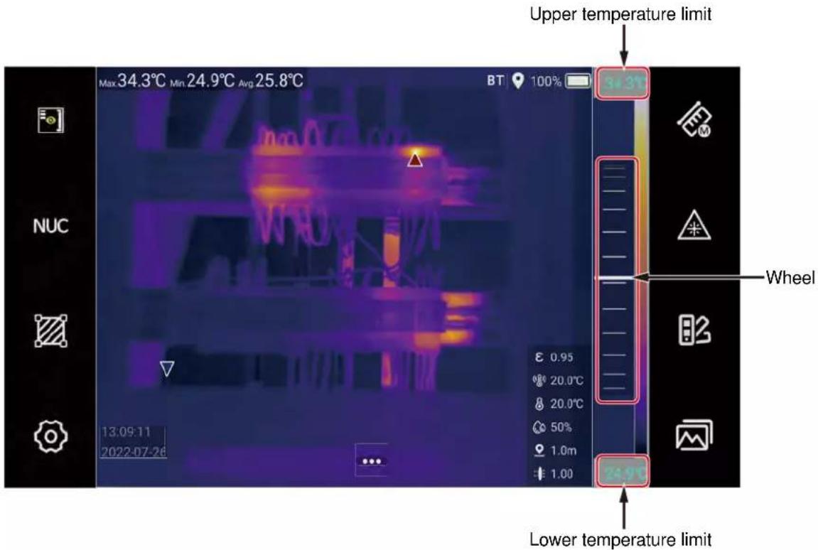
In Manual Span mode, the background of the upper and lower temperature limits on the color band is gray, and the span is adjustable. When there is no gray background on the upper and lower temperature limits on the color band, the span is locked. Tap the temperature limit to switch between locked and adjustable states, as shown in Figure 8.
Note
In Manual Range (mode, if the wheel does not appear on the screen, check the on-screen display settings, and make sure on-screen display is enabled). For on-screen display settings, see Shortcut Menu Area.
text_image
Upper temperature limit 34.3°C Min 24.9°C Avg 25.8°C BT 100% NUC Wheel 13:09:11 2022-07-26 ε 0.95 20.0°C 20.0°C 50% 1.0m 1.00 34.3°C Lower temperature limitFigure 8. Adjust Temperature Span Manually
To adjust temperature span manually:
- Tap temperature span icon so that it appears as 📋 to switch to Manual Range mode.
- Tap the upper and lower temperature limits as needed so that their backgrounds are grayed out.
- Scroll the wheel up or down to adjust the limits.
- When the upper and lower temperature limits on the color band both have gray background, both limits can be adjusted at the same time.
- When the upper temperature limit of the color band has gray background and the lower limit has no background color, the upper limit can be adjusted, and the lower limit remains unchanged.
- When the lower temperature limit of the color band has gray background and the upper limit has no background color, the lower limit can be adjusted, and the upper limit remains unchanged.
- When there is no gray background both for the upper and lower temperature limits on the color band, they are locked, and the upper and lower limits cannot be adjusted.
See Specifications for more information on minimum temperature span.
Laser Pointer
Tap and hold Laser Pointer key to turn on the Laser Pointer to locate the target to be measured; release the key to turn off the Laser Pointer.
When the laser is on, the laser icon is blue (▲), and the laser indicator (●) is shown on the screen; when the laser is off, the icon is white (△)

Warning
To prevent eye damage or personal injury:
- Do not look into the laser. Do not point laser directly at persons or animals or make it reflected indirectly from reflective surfaces.
- Do not disassemble the Product. The laser beam is dangerous to eyes. Have the Product repaired only through an approved technical service.
Color Palettes
With the palette function, you can select palettes and set color alarms (isotherms).
To choose a palette:
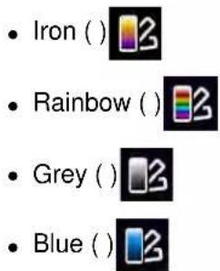
- Tap ☐2 (right Shortcut Menu Area). The palette menu shows and includes:
text_image
• Iron ( ) • Rainbow ( ) • Grey ( ) • Blue ( )Note
A hint for each button shows on the display. To view hints, use navigation keys to move the cursor between the icons. The function/status prompts for the button, as shown below.

text_image
RainBow Isotherm:Off-
Tap an icon to select a palette directly or tap ⋮. All palette options are shown.
-
To invert palette colors, tap 📋 in the upper-right corner of the screen. All palette colors will be inverted.
- Directly tap the palette to return to the Home screen or tap < in the upper left corner of the screen.
Enable / Disable Isotherm Function
Use the Isotherm (color alarm) function to set color alarm modes of high temperature and low temperature.
To set color alarms:
- Tap palette icon 📄 (right Shortcut Menu Area).
- In the Palette menu, tap ✦ to activate Color Alarms mode.
- Tap ✦ to switch between the alarm modes: high temperature and low temperature, or to turn off the Color Alarm mode.
- When the icon becomes ⚙, the high temperature color alarm mode is turned on, as shown in Figure 9.
Slide the temperature scale on the right to adjust the threshold of the high temperature alarm. The area where the temperature is higher than the temperature threshold shows in a fixed color by default (depending on the currently selected palette).
- When the icon becomes ✦, the color alarm mode of low temperature is turned on.
Slide the wheel on the right to adjust the threshold of low temperature alarm. The area where the temperature is below the temperature threshold is displayed in green by default. - Touch any other area of the screen to exit the Palette Settings menu.
- Tap the Color Alarm button when the icon is hollow ( ✦ ) to exit Color Alarm mode.

text_image
Max: 34.3°C Min: 24.9°C Avg: 25.8°C BT 100% 34.3°C 32.0°C E 0.95 ° 20.0°C ° 20.0°C 13:09:11 12:00:12:00 23 23 ... 23 ...Figure 9. High Temperature Color Alarm
Note
When the isothermal alarm is enabled, you cannot change the temperature span mode. If you tap 📄 or 📋, the screen prompts you to confirm whether to disable the isothermal mode. Select Isotherm Off to exit isotherm mode and you can change the temperature span mode. Select Cancel to return, you cannot change temperature span mode.
Gallery
Browse or analyze thermal images or fully-radiometric videos in the Gallery.
The thermal image files saved in the Gallery are identified by their names below the thumbnails on the left side of the Gallery, the types are;
- IR Thermal Image: IR_Date_Serial Number.jpg
- PIP Image: Mix_Date_Serial Number. jpg
- Visible Light Image: IMG_Date_Serial Number.png
- Visible Light Video: VD_Date_Serial Number. mp4
• Fully-Radiometric Video: Video_Date_Serial Number.is5
• Non-radiometric Video: VD_Date_Serial Number.mp4
text_image
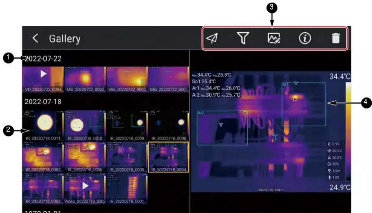
Gallery 1 2022-07-22 VD_20220722_0004 Mix_20220722_0003 Mix_20220722_0002 Mix_20220722_000 2022-07-18 IR_20220718_0011 IR_20220718_0010 IR_20220718_0009 IR_20220718_0008 IR_20220718_0007 IR_20220718_0006 IR_20220718_0005 IR_20220718_0004 IR_20220718_0003 Video_20220718_0002 IR_20220718_0001 1979-01-01 Max: 34.4°C Avg: 25.8°C Sp1: 25.4°C Ar1 Max: 34.4°C Avg: 26.0°C Ar2 Max: 30.9°C Avg: 25.7°C A#Z sp1 E 0.95 + 29.0°C & 29.0°C Qe 50% + 1.0m ↓ 1.00 34.4°C 24.9°CFigure 10. Gallery
Table 7. Gallery Operations
| No. Description | |
| 1 | Capture DateThe images and videos in the Gallery are sorted by when they were taken. |
| 2 | ThumbnailsImages and videos show as thumbnails. |
| 3 | Action ButtonsDepending on the type of image and video currently selected, some of these actions are available:-  Bluetooth Transfer-[40ZW] Filter by Tags- Bluetooth Transfer-[40ZW] Filter by Tags- Analysis- Analysis- Information- Information- Delete- Delete- Visible Light Images- Visible Light Images- Play Play |
| 4 | A preview of the currently selected image or video. |
To browse and select images:
- Tap 📂 (right Shortcut Menu Area). The Gallery shows as in Figure 10.
- On the left side of the Gallery, is the preview and selection area. Tap the preview to select a thermal image file or use the left and right navigation keys on the Imager to select the thermal image file to be analyzed and edited. On the preview on the right, you can enlarge and shrink the image by spreading or pinching with two fingers.
Gallery Operation
In the Gallery, you can do these operations (the available options depend on the thermal image file selected):
- Bluetooth Transfer. Tap the icon to send the currently selected thermal image/video to other Bluetooth devices. This function requires that Bluetooth is enabled, and the Bluetooth headset is not connected, see Settings.
- Filter by Tags. Tap the icon to go to the Search page where you can select one or more tags. The Gallery automatically filters out thermal image files with the tag(s). This helps to quickly find the desired thermal image file. See Tag for adding and editing tags.
-
Analysis. The images are analyzed in the Imager. For more information, see Thermal Image/Video Analysis.
-
Information. Display image details, including capture time, file type, file size, resolution, and storage path.
- Delete. Delete the original files stored in the Imager.
Delete one file: Select a file thumbnail from the Gallery, tap 📄 at the upper right corner of the Gallery, and a prompt box appears. Tap OK, to delete the selected file.
Delete multiple files: Tap and hold thumbnails in the Gallery to select multiple images; tap at the top of the screen, a prompt box appears. Tap OK, to delete the selected files. - Visible Light Images. Tap 📋, and a visible light image shows immediately.
- Play. Tap to play a fully-radiometric or non-radiometric video directly.
Basic Operation
Turn On and Off the Imager
Before you use the Imager for the first time, charge the battery for a minimum of 2.5 hours. See Charge the Battery.
To turn on or turn off the Imager, push Ⓐ and hold for 2 seconds.
To maximize the life of the battery, use the Power Save and Auto Off functions. See Settings for more information about how to set these functions.
After the Product is turned on, push Ⓞ, the Power menu shows. The menu includes options:
- Reboot: The Imager will be turned off and then restarted.
- Sleep: Set the Imager to Sleep mode. In Sleep mode, the screen is off and only the Power button is available; the Imager remains powered on and warmed up.
• Power off: Turn off the Imager.
In Sleep mode, push Ⓞ, the Imager quickly enters the operating state.
Note
All thermal imagers need sufficient warm-up time for accurate temperature measurements and best image quality. Warm-up time may vary by models and environmental conditions. Wait at least 20 minutes if the most accurate temperature measurement is important to your application. When you move an Imager between environments where the ambient temperature varies widely, allow for additional adjustment time.
Focus
Correct focus makes sure that the infrared energy is correctly directed onto the pixels of the detector. Without correct focus, the thermal image can be blurry, and the radiometric data may be inaccurate.
To focus with the advanced manual focus system, rotate the Manual Focus Control (6 in Figure 2) until the object is in proper focus.
Capture and Save Images
To capture an image:
-
Aim the Imager at the target and focus on it.
-
Push and release ☐ to capture and freeze the image. The image is saved in the memory buffer, and you can save or edit the image.
To edit an image, see Thermal Image/Video Analysis.
- Push □ again to save the image.
To take thermal images in different modes, see View Mode. To take fully-radiometric videos, see Capture Mode. To take non-radiometric videos, see Non-Radiometric Videos.
Digital Zoom
Use the Digital Zoom function to enlarge/shrink the live image or the thermal image being viewed.
In the image display area:
- Enlarge: Tap the screen with two fingers and spread them outward.
- Shrink: Tap the screen with two fingers and pinch them together.
- You can also slide the wheel at the bottom of the screen to enlarge/shrink.
In Live View mode, a digital zoom factor shows at the bottom of the screen, see Figure 11.

text_image
Max 34.3°C Min 24.9°C Avg 25.8°C BT 100% 34.3°C NUC 13:09:11 2022-07-26 Digital zoom factor 1.8x 0.95 20.0°C 20.0°C 50% 1.0m 1.00 24.9°CFigure 11. Enlarge/Shrink Images
System Menu
Use the System Menu to change and view settings.
Tap ... on the Home screen, the Main System menu shows at the bottom of the Main Display Area, as shown in Figure 12. Table 8 lists a brief description of each menu icon.

text_image
Max 34.3°C Min 24.9°C Avg 25.8°C BT 100% 34.3°C NUC E 0.95 20.0°C 20.0°C 6 71Figure 12. Main System Menu
Note
A hint for each button shows on the Imager's screen. To view hints, use navigation keys ☐ on the top of the Imager to move the cursor between the buttons. The function/status prompts for the current button shown on the screen.
Note
If the corresponding icon is grayed out or the button icon does not appear on the screen, make sure On-Screen Display is enabled (☐). For On-Screen Display settings, see Shortcut Menu Area.
Table 8. System Menu
| No. Description | |
| 1 |   pture modeThe available modes include:- S (27ZZ) e-capture- pture modeThe available modes include:- S (27ZZ) e-capture-  Frame Interval (push navigation button to see)- [X0AA] Timer (Set the frame rate/second.) Frame Interval (push navigation button to see)- [X0AA] Timer (Set the frame rate/second.) |
| 2 |   easurement settingsThe correction parameters that can be set include:- E (DXW7)ivity (default = 0.95)- [A24W] Reflected Temperature (default = 20 °C)- easurement settingsThe correction parameters that can be set include:- E (DXW7)ivity (default = 0.95)- [A24W] Reflected Temperature (default = 20 °C)-  Environment Temperature (default = 20 °C)- H (G407) dity (default = 50 %)- Environment Temperature (default = 20 °C)- H (G407) dity (default = 50 %)-  Distance (default = 1.0 m)- Distance (default = 1.0 m)-  Optical Transmittance (default 1.0)- Optical Transmittance (default 1.0)-  Base Temperature 20 °C (default = Off) Base Temperature 20 °C (default = Off) |
| 3 |   new modeView modes supported include:- IF new modeView modes supported include:- IF  de- D (X3TW)ode (visible image mode)- de- D (X3TW)ode (visible image mode)-  PIP Mode (picture-in-picture mode) including: PIP Mode (picture-in-picture mode) including:  Distar Adjustment and Transparency Adjustment [SXXC] Distar Adjustment Distar Adjustment and Transparency Adjustment [SXXC] Distar Adjustment  Transparency Adjustment Transparency Adjustment |

Table 8. System Menu (cont.)
| No. Description | |
| 4 |  Me Me  The temperature measuring tools provided include: The temperature measuring tools provided include: n of Interest (ROI) SelectionDispla n of Interest (ROI) SelectionDispla  Move Move  Adjus Adjus  Emiss Emiss  Delete Delete   ; ;     i i   i i   6 6   3### 3### |
| 5 |  Hig [1115]Enable/disable the alarm and limit settings. Hig [1115]Enable/disable the alarm and limit settings. |
| 6 |  Re Re  Record non-radiometric videos.Non-radiometric videos include non-radiometric infrared videos and visible light videos. Record non-radiometric videos.Non-radiometric videos include non-radiometric infrared videos and visible light videos. |
| 7 |  Sys Sys  For more information, see Settings. For more information, see Settings. |
Capture Mode
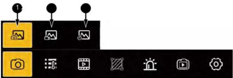
The Imager provides a variety of capture modes to choose from. The Capture Mode selection menu is shown in Figure 13.
text_image
Screenshot of a software toolbar with icons for image editing functions and camera controlsFigure 13. Capture Mode Menu
Table 9. Capture Mode Menu
No. Descrip  | |
| [XA2 GTZZ] Single capture | |
| 2 | Frame Interval |
| 3 | TimerSet the time interval between shots. |
Single-capture
In Single-capture mode, only an infrared thermal image or a picture-in-picture image (an infrared thermal image superimposed on a digital photo) is saved for each image capture.
See View Mode for information on view mode. See Capture and Save Images for how to capture images.
Frame Interval
In Fully-Radiometric Video mode, push ☐, the Imager starts to record a fully-radiometric video; push ☐ again, to stop the recording.
To preset the frame rate of video recording tap the buttons, the frame rate of video recording can be set between 1 Hz and 12 Hz.
To set frame rate:
- On the Main System Menu, tap

- In the menu, tap

-
Slide the wheel shown above the icon to select an appropriate frame rate, as shown in Figure 14.
-
In Capture mode, you can take a maximum of 1000 frames, and manually push to stop the recording.

text_image
Max 34.3°C 5 25:1 00:00:00 0/1000 BT 100% 34.3°C 4 3 2 1 12 11 10 9 NUC E 0.95 20.0°C 20.0°CFigure 14. Set Frame Rate
Timer
Before starting the Timer function, you can set the interval in advance. Set the Timer between 1 s and 60 m 59 s.
To set timer:
- On the Main System Menu, tap

- In the menu, tap

- Slide on the wheel shown above the icon to select the corresponding minute and second values. See Figure 15.
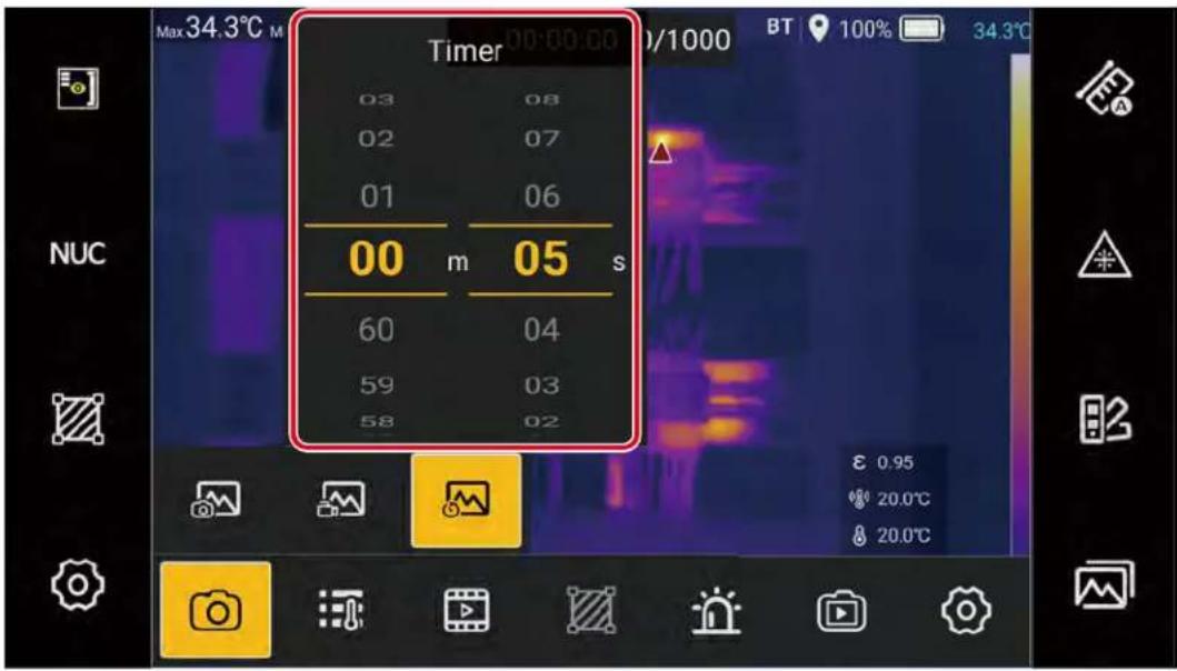
text_image
Max 34.3°C M Timer 03 02 01 00 m 05 s 60 59 58 08 07 06 05 04 03 02 BT 100% 34.3°C NUC E 0.95 20.0°C 20.0°CFigure 15. Timer
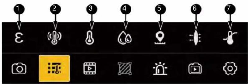
Measurement Settings
The Measurement Parameter Setting Menu is shown in Figure 16. The description of each icon is shown in Table 10.
text_image
1 2 3 4 5 6 7Figure 16. Correction Parameter Configuration
Table 10. Correction Parameters
| No. Description | |
| 1 | [ccwx] EmissivityThe actual emissivity of the target under measurement. |
| 2 |  Reflected TemperatureChange background temperature to compensate for or correct the background thermal radiation reflected from the target under measurement. Reflected TemperatureChange background temperature to compensate for or correct the background thermal radiation reflected from the target under measurement. |
Table 10. Correction Parameters (cont)
| No. Description | ||
| 3 |  | Environment Temperature |
| 4 |  | Humidity |
| 5 |  | Distance |
| 6 |  | Optical Transmittance |
| 7 |  | Base Temperature |
Emissivity
Emissivity refers to the ratio of the energy radiated by the object under measurement to the energy radiated by a black body at the same temperature and wavelength, and it is between 0 and 1.
All objects radiate infrared energy. The actual surface temperature and emissivity of the target affects the quantity of energy radiated. The Imager senses the infrared energy from the surface of the target and uses the data to calculate an estimated temperature value. Many common materials such as wood, water, skin, cloth, and painted surfaces, including metal, radiate energy well and have a high emissivity factor of ≥90% (or 0.90). The Imager can accurately measure the temperature of targets with high emissivity.
Shiny surfaces or unpainted metals do not radiate energy well and have a low emissivity factor of < 0.60 . Adjust the emissivity settings for the Imager to accurately measure targets with low emissivity.

Warning
To prevent personal injury, see emissivity information for actual temperatures. Reflective objects result in the temperature reading to be lower than it actually is. These objects pose a burn hazard.
The Imager emissivity settings include Full-Screen Emissivity Correction and Area Emissivity Correction. For Area Emissivity Correction settings, see ROI Operation.
To set full-screen emissivity:
- In Measurement Settings menu, tap 8
- To customize material emissivity, slide up and down the emissivity values (0.01 to 1.0) on the left side of the screen.
- If the material of the object under measurement is known, you can slide up and down the Material Emissivity Reference Table on the right side of the screen to select the corresponding material.
- Tap the screen outside the pop-up window or push 📋 to return.
Reflected Temperature
Reflected temperature is used to compensate or correct the thermal radiation reflected from the target under measurement. When the target is surrounded by very hot or very cold objects, the measurement accuracy can be affected, especially when the surface emissivity of the target is low. Adjust reflected background temperature to improve measurement accuracy.
To set reflected temperature:
- First use the Imager to test the actual temperature of the reflector near the target.
- Tap .
- Slide the screen up and down to set the Reflected Temperature to the temperature of the reflector measured by the Imager.
- Tap other areas of the thermal image screen or push 📊 to complete the Reflected Temperature settings.
Environment Temperature
Environment temperature refers to the air temperature between the Imager and the target.
To set environment temperature:
- Tap .
- Slide the screen up and down to set Environment Temperature value to the actual air temperature.
- Tap other areas of the thermal image screen or push 📊 to complete the Environment Temperature settings.
Note
Environment Temperature is usually a default value, set the Environment Temperature only when the air temperature is higher than the actual temperature of the target under measurement.
Humidity
The Imager can compensate for the local effects of air humidity on thermal radiation transmission. Make sure to set the humidity correctly.
To set humidity:
- Tap

-
Slide the screen up and down to set the humidity percentage to the actual value.
-
Tap other areas of the thermal image screen or push ↻ to complete the settings.
Note
For short distances and normal humidity, humidity is usually a default value for the Imager.
Distance
The Distance refers to the distance between the target under measurement and the Imager lens. Use distance to compensate for:
- The thermal radiation from the target being measured absorbed by the air between the target and the lens.
• Thermal radiation from the air itself detected by the Imager.

text_image
Max:34.3°C Min:24.9°C Avg:25.8°C 5.0 4.0 3.0 2.0 1.0 0.9 0.8 0.7 0.6 34.3°C NUC E i o i o i i i i i i i i i i i i i i i i i i i i i iTo set distance:
- Tap

-
Slide the distance value on the screen up and down to set the distance value to the actual distance between the target under measurement and the Imager lens.
-
Tap other areas of the thermal image screen or push ↻ to complete the settings.
Transmittance
Optical transmittance refers to the transmittance of external lens or IR window used in front of the Imager lens.
When IR inspection is performed through an IR window, not all of the IR energy emitted by the target is transmitted through the optical material of the window. If the transmittance of the window is known, the transmittance percentage can be adjusted in the Image or the SmartView IR software to improve measurement accuracy.
To set transmittance:
-
Obtain the actual transmittance of the external lens or external IR window.
-
Tap .
-
Slide up and down the transmittance values on the screen (0.01 to 1.0) to set it to the actual values measured.
-
Tap other areas of the thermal image screen or push 📄 to complete the settings.
Note
If optional external optical lens has been calibrated at the factory, or there is no external infrared window, optical transmittance is usually the default value of the Imager.
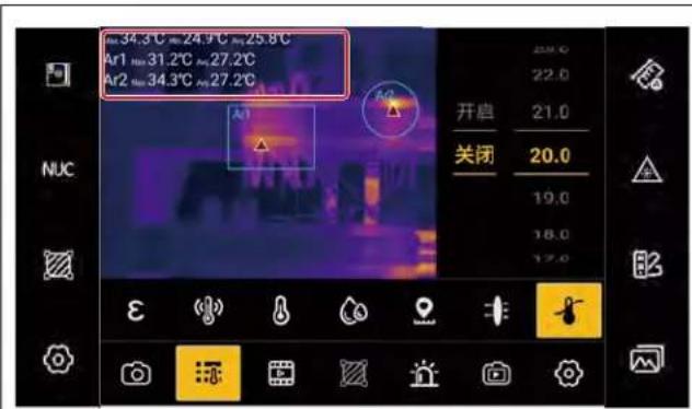
Base Temperature
After Base Temperature is enabled, the temperature value displayed on the full screen (including full screen temperature and marker temperature) is the difference between the actual temperature and the reference temperature. Figure 17 shows a comparison of measurement readings before and after applying base temperature.
text_image
34.3℃=24.9℃=25.8℃ Ar1 Ar2 31.2℃=27.2℃ Ar3 34.3℃=27.2℃ NUC 开启 21.0 关闭 20.0 19.0 18.0 17.0 E 示 示 示 示Before After

text_image
14.3°C 4.9°C Avg 58°C Avg 20.0°C Ar1 11.2°C Avg 7.2°C Ar2 14.3°C Avg 7.2°C Ar 开启 20.0 关闭 19.0 16.0 17.0 NUCFigure 17. Before and After Applying Base Temperature
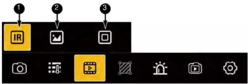
View Mode
The view modes supported by the Imager include IR, DC and Picture-in-Picture (PIP) mode.
The View Mode Settings menu is as shown in Figure 18, and the meaning of each icon is shown in Table 11.
text_image
1 IR 2 3Figure 18. View Mode Selection
Table 11. View Mode Selection
| No. Tool | Description | |
| 1 |  | IR ModeIn this mode, the screen shows infrared images; push to save a single-frame thermal image. |
| 2 |  | DC Mode In this mode, the screen shows visible light images shot by the digital camera. |
| 3 |  | PIP ModeIn this mode, an infrared thermal image is superimposed on a digital photo. You can adjust the position and transparency of infrared images.See PIP Mode for details. |
PIP Mode
In Picture-in-Picture (PIP) mode, an infrared thermal image is superimposed on a visible digital photo, as shown in Figure 19.
When you select Picture-in-Picture (☐) mode, the PIP menu appears so you can adjust the image.
In PIP mode, push □ to save a thermal image and a visible photo associated with it.
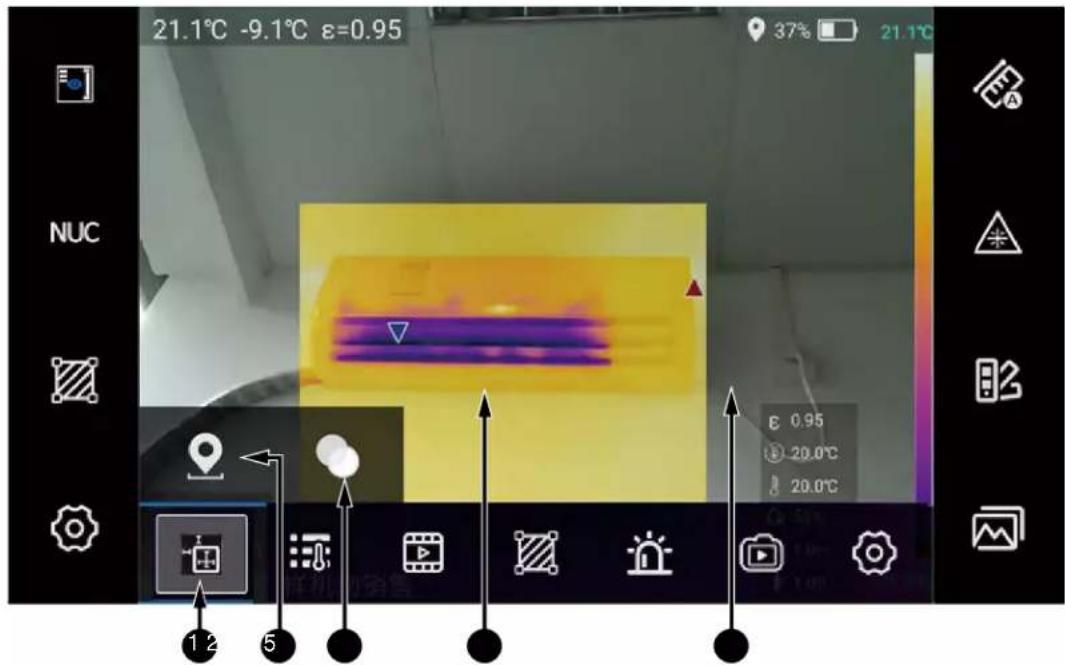
text_image
21.1°C -9.1°C ε=0.95 37% 21.1°C NUC E 0.95 20.0°C 20.0°C 1 2 5Figure 19. PIP Mode
Table 12. PIP Mode
| No. Tool | Description | |
| 1 | Adjustment Menu | |
| 2 | PositionAdjust the position so the infrared image is in the desired position. | |
| 3 | TransparencyAdjust the transparency of infrared images. |
The Infrared lens and the visible lens use two independent optical paths. When you change the distance to the target under measurement, the picture-in-picture can overlap and misalign. Use the Position Adjustment function for fine-tuning.
To adjust position:
- In the PIP mode menu, tap

The System menu is replaced by the Position Adjustment wheel.
-
Use your finger to slide the wheel left and right and observe the changes of the image on the screen. Adjust the position of the infrared image and the visible image to coincide with each other.
-
Tap X or push ☑ to complete the PIP position adjustment.
To adjust transparency:
- In the PIP mode menu, tap

The System menu is replaced by the Transparency Adjustment icon and the current value is shown. The adjustment range is 0 to 1.0.
- Tap ☐ to reduce the transparency of an infrared image or ☐ to increase the transparency of an infrared image according to field measurement requirements. 0 indicates the infrared image is completely transparent, 1.0 indicates the infrared image is completely opaque.
- Tap X to complete the transparency adjustment settings.
Note
In the picture-in-picture (PIP) mode, make sure that the Imager is accurately focused. Otherwise, the temperature measurement accuracy of the Imager is affected.
Measuring Tools
The Imager has a set of measuring and analysis tools, such as the measurement of maximum/average/minimum temperatures and temperature differences in a specific area.
To access the Measuring Tools menu, tap 📋 (left Shortcut Menu Area) of the Home screen, or tap 📋 from the System menu, as shown in Figure 20.

text_image
Screenshot of a software toolbar with icons for image editing functions and a highlighted yellow buttonFigure 20. Measuring Tools
Table 13. Measuring Tools
| No. Tool Description | ||
| 1 |  | SelectSelect an appropriate ROI. |
| 2 |  | Circle (Ar)Add a measurement area of circle. |
| 3 |  | Rectangle (Ar)Add a measurement area of rectangle. |
| 4 |  | Line (Li)Add a line measurement. |
Table13. Measuring Tools (cont.)
| No. Tool Description | |
[6T3  | Spot (Sp)Add a point measurement. |
[K3A  | Temperature DifferenceA temperature difference calculation tool that can calculate temperature difference between temperature measurement markers or between temperature measurement markers and fixed temperature values. |
 | DeleteDelete all ROIs. |
ROI stands for Region of Interest.
ROI can be a circle, a rectangle, a line or a spot. The name of a circle is prefixed with Ar, that of a rectangle is Ar, that of a line is Li, and that of a point is Sp.
On-screen display shows the ROI shape, name, the highest temperature point and its temperature value, the lowest temperature point and its temperature value, and the emissivity of different ROIs.
To add a ROI
- On the live image screen, the image freeze screen, or the image screen in the Gallery, tap

- Tap to select a measuring tool from the menu at the bottom of the screen.
- Draw a ROI in the corresponding area of an image. The method for drawing a ROI varies slightly depending on the tool selected, see Table 14.
Table 14. Draw a ROI
| Tool Methods | |
 | Rectangle (Ar)Tap to automatically add a rectangle to the image area. The rectangle has control points at each corner. Tap other positions in the thermal image, and the control point marks of the rectangle disappear, indicating that the rectangle is not currently selected.The default name of the ROI is in the form of "Ar+number", where the number refers to the serial number of the rectangular area.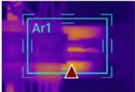 |
 | Circle (Ar)Tap to automatically add a circle to the image area to designate a circular temperature measurement area.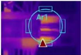 The name of the circle is prefixed with Ar. The name of the circle is prefixed with Ar. |
| [BZ7Y] | LineTap the icon to add a line to the image area.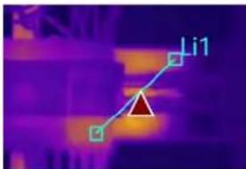 The name of the line is prefixed with Li. The name of the line is prefixed with Li. |
 | SpotTap the icon to add a cross mark to the thermal image.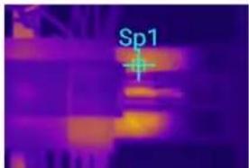 Its name is prefixed with Sp. Its name is prefixed with Sp. |
ROI Operation
After a ROI is established, you can do a series of operations.
To select a ROI:
- In the Measuring Tool menu, tap

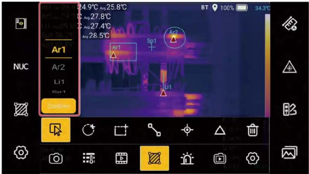
A list of all current ROIs appear above the tool icon, as shown in Figure 21.
text_image
Ar1 Avg 25.8°C Avg 27.8°C Avg 27.4°C Avg 28.5°C Ar1 Sp1 Ar2 Li1 Li1 Confirm NT 100% 34.3°C NUCFigure 21. Select a ROI
- Swipe up and down in the ROI selection area on the left side of the screen to select the ROI to be adjusted.
- Tap Confirm.
The temperature information of the selected ROI show in green at the top left of the screen and the outline of the selected ROI is highlighted.
A series of ROI tools show at the bottom of the screen, as shown in Figure 22, where the ROI Ar2 is selected.

text_image
Selected ROI Max 34.3°C Min 24.9°C Avg 25.8°C BT 100% 34.3°C Ar1 Max 31.2°C Avg 27.8°C Ar2 Max 34.3°C Avg 27.4°C Li1 Max 28.8°C Avg 28.7°C Sp1 26.1°C NUC Ar1 Sp1 Li1 ε 0.95 20.0°C 8 20.0°C 1 2 3 4 5 6Figure 22. ROI Adjustment Tools
Table 15. Adjustment Tools
| No. Tool Description | ||
[565]  | SelectSelect an ROI. | |
 | Display setCustomize the ROI information of the On-screen Display including Max, Min, Avg, Marker, and Emissivity. | |
 | MoveMove an ROI. | |
 | ResizeAdjust the ROI size | |
 | EmissivitySet the emissivity of a ROI. | |
 | Delete ROIDelete the ROI selected. | |
To move an ROI:
-
Tap the menu area.
-
Use ☐ to move the selected ROI in 4 directions.
Or
Tap and hold the ROI and move the ROI to the position you want to observe.
To adjust an ROI:
-
Tap in the menu area.
-
Use □ to adjust the selected ROI in 4 directions.
Or
Tap and hold the ROI outline, and swipe up, down, left, and right to adjust the size of the ROI.
To set the emissivity of an ROI:
- Tap £ he menu area.
An interface for customizing emissivity values and an emissivity table shows on the screen. You can customize the emissivity values or set the values in the emissivity table.
- Set the emissivity for this ROI. The procedure for setting emissivity of ROI is like that for setting emissivity of full screen, see Emissivity for details.
To set the ROI display
- Tap the menu area.
The display set interface is shown in Figure 23.
- Tap a switch button to enable or disable the display of the corresponding information.
When the button is on the right (colored), the information is shown. When the button is to the left (gray), the information does not show.

text_image
Display set Max Min Avg Marker Emissivity Sp1 Ar2 L1 0.95 20.0°C 20.0°CFigure 23. ROI Display Set
To delete an ROI:
- Select an ROI and tap 📋 in the menu area.
To delete all ROIs, see Table 13.
- When you are done, tap other area of the screen, or push

Temperature Difference Calculation
You can set temperature difference calculation between temperature measurement markers or between a temperature measurement marker and a fixed temperature value.
To set temperature difference calculation:
- In the Measuring Tools menu, tap △.
The interface for temperature difference calculation settings show on the screen, see Figure 24.
In the interface of temperature difference calculation settings, the first column is function switch, followed by Condition1, Condition2 and TREF.
The temperature difference is calculated as: Temperature Difference = Condition1 - Condition2.
- Turn on the function switch.
- Select Condition1 and Condition2 as required.
The options for Condition1 and Condition2 includes, if applicable, the maximum temperature, the minimum temperature, and the average temperature of each ROI. The Condition 2 also includes TREF.

text_image
Max 34.3°C Min Ar1 Max 31.2° Ar2 Max 34.3° Li1 Max 28.5° Sp1 26.1°C Condition1 Condition2 TREF 23.0 22.0 21.0 On Ar1.Max Ar1.Max 20.0 Off Ar1.Min Ar1.Min 19.0 Ar1.Avg Ar1.Avg 18.0 Ar2.Max Ar2.Max 17.0Figure 24. Temperature Difference Calculation Settings
- If Condition2 is selected with TREF, you must set TREF correctly.
- After completing all settings, tap other areas of the screen, or push 📋. The temperature difference calculation formula and the temperature difference value show on the Home screen.
Audible Alarm
The Imager provides high and low temperature audible alarms, so you can set an upper and/or lower temperature limit. When the measured temperature is higher than the upper limit or lower than the lower limit, a sharp and rapid beep is triggered to alert users.
To set an audible alarm:
-
Tap in the System menu to display the interface for audible alarm settings on the screen.
-
Set the High Temperature and/or Low Temperature to On.
-
In the High Temperature and/or Low Temperature column, slide up and down to select a temperature value.
-
After completing all settings, tap other areas of the screen, or push

Non-Radiometric Videos
The Imager can record non-radiometric videos, including non-radiometric IR videos and non-radiometric visible light videos. The type of video recorded depends on view mode settings, see View Mode.
To record a non-radiometric video:
-
Tap in the system menu and the Imager prompts to start recording. Push OK.
-
Tap Start Now in the pop-up dialog box. If you do not want to be prompted next time, check No prompt any more option.
The Imager immediately starts recording a non-radiometric video and the recording indicator and duration of recording show at the top of the screen.
- To stop video recording, push ☐ once, the Imager will stop recording and save the recorded video immediately, and briefly display the saved file name and thumbnail at the bottom of the screen, as shown in Figure 25.
A non-radiometric video is named VD_date_SequenceNumber.mp4.

text_image
VD_20220728_0008.mp4Figure 25. Record a Non-radiometric Video - Pause
The Imager restores the live image screen and you can continue recording a video or perform other operations.
Settings
The Settings menu mainly contains some system settings of the Imager itself. When necessary, use this menu to restore the Imager to the factory settings.
To enter Settings menu:
- On the Menu screen, tap 📋 at the bottom of the screen.
The options show on the main display area of the Imager. For details, see Table 16.
Table 16. Settings Menu
| Item Options | Description | |
| Language & DateTime | Language | Select the language for the interface. |
| Time Zone | Select the local time zone.The default time zone is GMT+08:00 Hong Kong/China. | |
| Date | Set the year, month, and day of the built-in calendar in the Imager. | |
| Time | Set the time for the built-in clock in the Imager. | |
| Unit | Temperature Unit | The Imager offers a wide selection of temperature units. |
| Distance Unit | The Imager offers a wide selection of distance units. | |
| Image & Display | TFocus | Choose to enable or disable TFocus. SeeTFocus Technologyfor details.The default setting is: Off. |
| TWB | Choose to enable or disable the high temperature differential imaging technology (TWB). SeeTWB Technologyfor details.The default setting is: Off. | |
| Information displayed on an image | Set the information that shows on an image:Global maximum temperatureGlobal minimum temperatureGlobal average temperatureEmissivityReflected temperatureEnvironment temperatureHumidityTest distanceOptical transmittanceNoteThe emissivity shown here is the full screen emissivity displayed at the bottom right, seeROI Operationfor emissivity of ROIs | |
| Accessibility | Location Services | Enable or disable the GPS function.The default setting is: Off |
| Sounds | Adjust the sound volume.The default setting is: 70 % | |
| Screen brightness | Adjust the screen brightness.The default setting is: 50 % | |
| Screen-off time | Enable or disable the auto screen-off function and adjust the time before screen turns off.The default setting is: Never (The screen-off function is disabled.) | |
| Auto sleep | Enable or disable the auto sleep function of the Imager. If the function is enabled, the Imager will automatically enter sleep mode after the screen is off for 5 minutes.The default setting is: Off. | |
| Flashlight | Turn on or off the LED Flashlight function.The default setting is: Off | |
| HDMI | Enable or disable the video streaming output of the HDMI video interface.The default setting is: Off | |
| AI NUC | Enable or disable the AI NUC. | |
| Eyepiece | An external electronic eyepiece can be connected to the HDMI interface. | |
| Bluetooth Bluetooth On/Off | Tap the Bluetooth button to enter the sub-menu for Bluetooth connection. When Bluetooth is enabled, the button shows in yellow.The default setting is: Off. | |
| When Bluetooth is enabled, tap Headset, select the Bluetooth headset that can be searched to complete the pairing of Bluetooth devices. When the pairing is successful, “Connected” shows. | ||
| Temperature Range | Select | When measuring temperature, an appropriate temperature range should be set in advance. If the displayed temperature value exceeds the selected range, a < or > symbol shows in front of the value. |
| Storage & Save | Image format | General format/State grid format |
| SuperResolution | Turn on/off the SuperResolution function that can increase the pixels of the captured thermal image by 4 times.The default setting is: Off. | |
| Visible light cameraPrompts when saving | Turn on/off the visible light camera.When the visible light camera is turned on, the current visible light image will be saved.The default setting is: Off.Set the prompts when saving images:Floating window. (default) After a thermal image file is captured and saved, the current interface shows the file information for 1 to 2 seconds.None. There are no prompts when a thermal image is captured and saved.Dialog. After a thermal image file is captured and saved, the file information shows in a dialog box. Tap other areas of the screen, or pushto close the dialog box. | |
| Storage location | The storage location can be set to the internal storage or an external SD card.When there is no memory card, this option is grayed out and cannot be modified. | |
| Internal storage | Display the current internal storage usage. | |
| External storage | Display the current storage usage of the SD card. | |
| Uninstall the SD card | To remove the SD card from the Imager, tap Uninstall SD card, to prevent data loss and damage to the SD card. | |
| Reset | Restore to factory defaults | Parameters are reset to factory default settings. |
| Delete all files | Delete all saved files | |
| The Imager information | Model | Model information |
| Serial Number | Serial number | |
| Software version | Software version information | |
| System version | System version information | |
| The Imager version | Version information for the Imager | |
| Lens | Lens focal length. | |
| Status information | Status information. | |
| System upgrade... | Upgrade the system (upgrade package file is required). | |
Note
If you forget to modify some parameters during the test and it affects the imaging and temperature measurement accuracy, use Restore to factory defaults to reset the parameters to factory defaults. The Imager automatically restarts after the parameters are restored to default settings.
Note
To delete all test data from the Imager, use Delete all files, the Imager deletes all the files in the storage and the files cannot be recovered, then the Imager automatically restarts.
Regional Intelligent Temperature Span Adjustment
Use the regional intelligent temperature span adjustment function if you take a thermal image on site and need to adjust the temperature span of some specific areas in the thermal image. In addition to the manual temperature span adjustment function, Fluke recommends you use the regional intelligent temperature span adjustment function, to detect abnormal phenomena and small temperature differences in the relevant images. You can get correct diagnosis conclusion quickly on site.
To use the regional intelligent temperature span adjustment function:
- Tap ... on the Home screen to show the additional system function buttons.
-
Tap of the Imager to enter the main interface of the system settings.
-
Tap Image & Display to enter the Image & Display sub-menu.
-
Tap TFocus in the System menu to disable it.
-
Push once to enter the image freeze screen.
-
Tap 📋 to use the regional intelligent temperature span adjustment function.
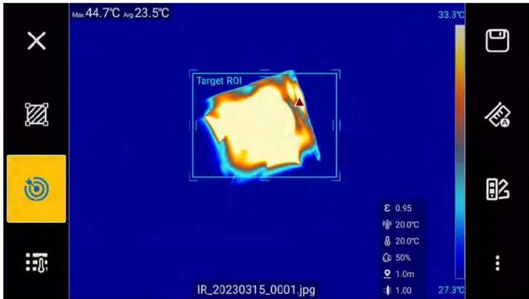
The Target ROI appears in the middle of the screen. After the Target ROI is enabled, the suitable temperature span of the ROI is calculated automatically and the threshold is adjusted, and the ROI is highlighted.
-
You can move, enlarge, or shrink the ROI to select the area to adjust. See ROI Operation.
-
You can enable or disable the function on the Analysis interface, see Settings.
text_image
Max.44.7°C Avg 23.5°C 33.3°C Target ROI ε 0.95 20.0°C 20.0°C 50% 1.0m IR_20230315_0001.jpg 1.00 27.3°CFigure 26. Regional Intelligent Temperature Span Adjustment
TWB Technology
In general, the thermal image color is uniformly distributed in a linear way (linear color distribution) from the lowest to the highest temperature.
If there are many high-temperature interference sources on site, and the interference and the target under measurement all appear in the same field of view, then the greater the temperature difference between them. This makes it more difficult for the linear color distribution to clearly show the thermal gradient of the target under measurement. An example of such case is shown in Figure 27.
text_image
NUC ...Figure 27. The Image Before TWB Technology
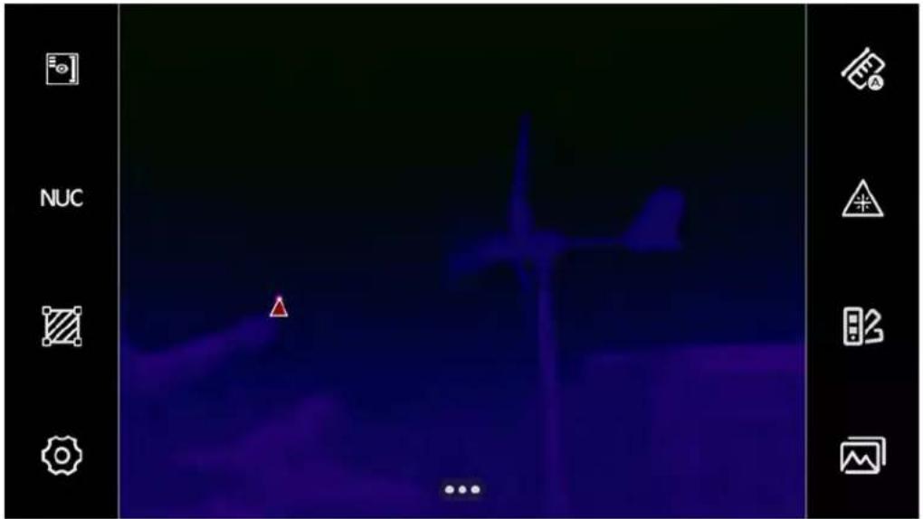
The TWB technology can help you clearly display the thermal gradient details of all target objects in high temperature difference scenario, as shown in the Figure 28.

natural_image
Thermal image of a wind turbine against a sunset sky, with UI icons for camera, lens, and camera (no readable text or symbols on the turbine itself)Figure 28. The Image After TWB Technology
To use the TWB technology:
-
Tap ... the Home screen.
-
Tap 📋 to enter the main interface of the system settings.
- Tap Image & Display to enter the Image & Display sub-menu.
- Tap TWB in the view mode sub-menu to enable the TWB function.
- Push 📋, then the Imager will distribute colors based on the thermal imaging content of the image (histogram color assignment). The temperature scale on the right side of the screen shows the maximum and minimum temperatures for the current temperature span.
TFocus Technology
If the target under measurement is in a very complex scenario, you must distinguish the thermal gradient details of the target. Fluke recommends you use the TFocus technology to enhance the display of specific targets and automatically shield background interference sources. TFocus analyzes the subtle temperature difference of specific targets in complex scenario to get the correct diagnosis conclusion quickly on site.
To use TFocus technology:
- Tap ... on the Home screen of the Imager to call up the hidden system function.
- Tap 📍 to enter the main interface of the system settings.
- Tap Image & Display to enter the Image & Display sub-menu.
- Tap TFocus in the View Mode sub-menu to enable the TFocus function.
- Push once to enter the image freeze screen.
- Tap 📋 to use the TFocus technology.
The ROI appears in the middle of the screen, and the temperature values at the top and bottom of the color band on the right side of the Imager screen automatically show the highest and lowest temperatures in the ROI.
- You can move, enlarge, or shrink the ROI to select the target under measurement for enhanced display. See ROI Operation for ROI operations.
The image in the selected target ROI is enhanced with the color of the current palette and the color of the rest of the thermal image displays in gray.
- You can enable or disable the function on the Analysis interface, see Settings.
natural_image
Thermal imaging view of a red and yellow object with surrounding purple and green patterns (no text or symbols)
natural_image
Thermal imaging view of a device with a color-coded heat map overlay (no text or symbols)Figure 29. Image Comparison Before and After TFocus Technology
Thermal Image/Video Analysis
The Imager has measuring and analysis tools in the Image Freeze and Gallery View interfaces. The Imager can accurately diagnose and analyze the target at the test site without analysis software for PC.
Depending on different capture modes, the images that can be analyzed include:
• Fully-Radiometric Thermal Images
- PIP Images
• Fully-Radiometric Videos
The analysis operation of a thermal image/video is similar whether it is an image/video in the image freeze interface during shooting or an existing file opened from the Gallery.
The following takes an image/video in the image freeze interface during shooting as an example to introduce the thermal image/video analysis. For the analysis of a thermal image/video in the Gallery, the differences, if any, are presented in the form of notes.
Thermal Image
The Image Freeze interface in Thermal Image mode is as shown in Figure 30. See Table 17 for the function and description of each button.

text_image
Max 34.3°C Min 24.9°C Avg 25.8°C Ar1 Max 31.2°C Avg 27.8°C Ar2 Max 34.3°C Avg 27.4°C Li1 Max 28.5°C Avg 28.5°C Sp1 26.1°C Ar1 Sp1 Ar2 Li1 ε 0.95 20.0°C 20.0°C IR_00220725_0004.jpg 24.9°C ① ② ③ ④ ⑤ ⑥ ⑦ ⑧ ⑨Figure 30. Thermal Image Freeze Screen
Table 17. Thermal Image Freeze Screen
| No. Tool Description | ||
| 1 |  | CloseTap to exit the current interface or menu bar. |
| 2 |  | Measuring ToolsTap to enter the measuring tool sub-menu. See Measuring Tools. |
| 3 |  | ROIUse to select an ROI that includes TFocus and TWB functions. See TWB Technology and TFocus Technology for details. |
| 4 |  | Measurement ParametersUse to select full-screen measurement parameters. Tap to enter the sub-menu for modifying full-screen measurement parameters. See Measurement Settings. |
| 5 |  | SaveTap to automatically save the currently displayed file to the Imager. |
| 6 |  | Temperature SpanThe shortcut button for switching between Auto Span and Manual Span. See Temperature Span Mode. |
| No. Tool | Description | |
| 7 |  | Color PalettesUse to set color palettes. Tap to enter the sub-menu for quickly switching palettes.SeeColor Palettesfor details. |
| 8 |  | MoreTap to open more function buttons. |
| 9 |  | Voice AnnotationTap to open the sub-menu for voice annotation. You can directly record/play a voice annotation and automatically associate it with a thermal image. SeeVoice Annotationfor details. |
| 10 |  | Text RemarkTap to open the sub-menu for text remark. You can directly add and edit text information and automatically associate it with a thermal image. SeeText Remarkfor details. |
| 11 |  | TagTap to open the sub-menu for editing tags. You can directly add/delete/manage tag information and automatically associate it with a thermal image. SeeTagfor details. |
| 12 |  | ScanningTap to enable the scanning function. You can scan and read the information of a QR code/barcode and automatically associate it with a thermal image. SeeAutomatically Naming the Thermal Image Files Scanned. |
Note
When opening a thermal image file from the Gallery for analysis, instead of displaying Scan 📄, Info 🟢 shows in the interface. Tap 🟢 to see information about the thermal image/video at the bottom of the screen as shown below.
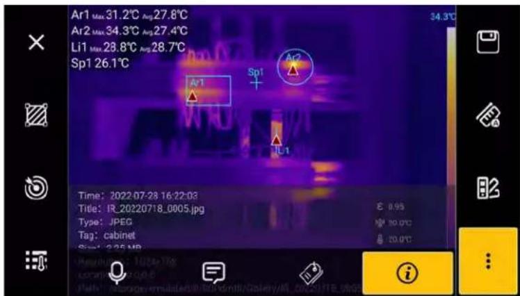
text_image
Ar1 Max 31.2°C Avg 27.8°C Ar2 Max 34.3°C Avg 27.4°C Li1 Max 28.8°C Avg 28.7°C Sp1 26.1°C Time: 2022-07-28 16:22:03 Title: IR_20220718_0005.jpg Type: JPEG Tag: Cabinet Signal: 2.25 MB E 0.95 M 30.0°C D 30.0°C iPicture-in-Picture (PIP)
The image freeze interface in PIP is the same as that of the Thermal Image Freeze mode, see Table 17.
Fully-Radiometric Videos
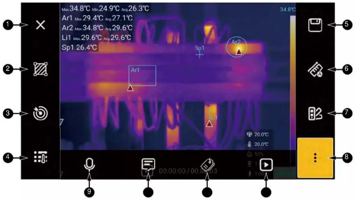
text_image
Max 34.8°C Min 24.9°C Avg 26.3°C Ar1 Max 29.4°C Avg 27.1°C Ar2 Max 34.8°C Avg 29.6°C Li1 Max 29.6°C Avg 29.6°C Sp1 26.4°C 34.8°C Sp1 Ar2 Ar1 Li1 20.0°C 20.0°C 50% 100% 9 00:00:00 / 00:00:03 100%Figure 31. Fully-radiometric Video Freeze Screen
Table 19. Fully-radiometric Video Freeze Screen
| No. Description | |
| 1 to 11 |  See 1 to 11 in Figure 30.See Thermal Image. See 1 to 11 in Figure 30.See Thermal Image. |
| 12 |  Use to control videos.Tap to play thermal videos on the current screen.Tap to pause the thermal video that is playing on the current screen.When previewing and playing thermal videos, the Play button changes to the Pause button. Use to control videos.Tap to play thermal videos on the current screen.Tap to pause the thermal video that is playing on the current screen.When previewing and playing thermal videos, the Play button changes to the Pause button. |
Automatically Name Scanned Files
The thermal image files can be automatically named with the information contained in the QR code. The files are saved in the Imager.
When the screen is frozen:
- Tap

- Aim at the QR code to be scanned, the QR code information is read automatically, and a dialog box containing the QR code information will automatically show.
-
Tap OK, the name of a thermal image file shows at the bottom of the Imager screen.
-
In IR mode, the name format of the thermal image file: IR_Date_Sequence Number_QR code content.file format.
-
In PIP mode, the name format of the thermal image file: Mix_Date_Sequence Number_QR code content.file format.
-
Push or tap Save, the Imager will automatically name a thermal image file with the QR code information and save it.
Note
The QR code used for scanning must be clear, otherwise the Imager may not be able to read it.
Add an Annotation
You can save additional annotation with the thermal image file. Annotation can provide important information about an image (for example, conditions and information about where the image was captured), for reports and post-processing.
Annotation information are added to a thermal image file and can be viewed and edited both in the Gallery and the thermal image analysis software for PC.
Note
Adding annotation to saved thermal image files in the Gallery is similar.
Voice Annotation
You can add voice annotation to thermal image files. With this function, you can record a voice annotation through a connected Bluetooth headset or the Imager microphone.
To add a voice annotation:
- Tap 📋 to enter the sub-menu for voice annotation.
- Tap ☐ to start recording. You can also tap to re-record a voice annotation which automatically overwrites and replaces the existing annotation.
- Tap to stop recording.
-
Tap ▶ to play the recorded voice annotation.
-
Tap ☐ to delete the currently recorded voice and record again.
-
After recording, tap ✗ to close the voice annotation interface, and save the annotation to a thermal image file.
Text Remark
You can add a text remark to thermal image files by entering text on the Imager screen.
To add text remark:
-
Tap ☐ to enter the sub-menu for text remark.
-
Tap the text box, a soft keyboard will automatically pop up at the bottom of the touch screen.
-
After inputting the text remark, tap the blank area on the screen to exit the soft keyboard.
-
Tap to automatically save the text in a thermal image file.
Tag
You can add a tag to a thermal image file to quickly filter and search the thermal image files in the Gallery.
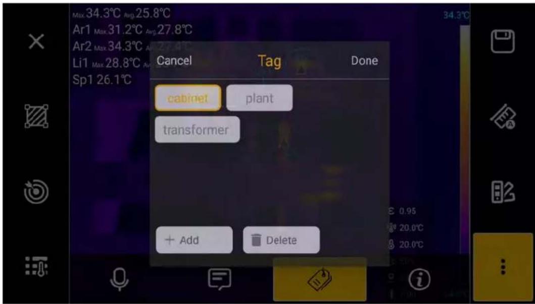
text_image
Max 34.3°C Avg 25.8°C Ar1 Max 31.2°C Avg 27.8°C Ar2 Max 34.3°C Avg 27.8°C Li1 Max 28.8°C Avg 27.8°C Sp1 26.1°C Cancel Tag Done cabinet plant transformer + Add Delete 0.95 20.0°C 20.0°CFigure 32. Add a Tag
To select a tag:
- Tap 📋 to enter the sub-menu for tags.
- Tap Add and tap the text box, a soft keyboard will automatically show, and an appropriate text input method will be applied.
- After you input a tag, save the tag to the list. Tap the down arrow on the soft keyboard to exit the soft keyboard.
- Tap Done to save the tag; select the tag to be added (highlighted) and tap Done to automatically save the tag in a thermal image file.
- To detach the tag from an image, deselect the tag (not highlighted) and tap Done.
- To delete a tag, select the tag (highlighted in yellow) in the tag list and tap Delete and then tap Done.
SmartView™ IR Software
You can use the Fluke SmartView IR software with the Imager. The software contains functions for analyzing images, organizing data and information, and generating professional reports.
Use the SmartView IR software to:
• Stream fully-radiometric videos
- Create fully-radiometric videos/images
- Analyze images
- Plot data trends
- Export data
- Customize reports
Download and Install the SmartView IR Software
On the PC, go to: https://www.fluke.com/smartview-ir.
- Download the SmartView IR software to the PC according to the instructions on the Product page.
- On the PC, follow the instructions to install the software. (Administrator privileges are required for the installation.)
For details on remote viewing and control of the Product connected to the SmartView IR software, please see the instructions of the software.
Note
Before connecting the Imager to the analysis software for PC, turn off the visible light camera of the Imager. For details, see Settings.
Real-time View and Record Fully-Radiometric Video Streaming
To view and record in real-time a fully-radiometric video streaming taken by the Imager on a PC via the Fluke SmartView IR software:
- Turn off the visible light camera on the Imager. See Settings.

text_image
> Storage & Save DC Camera >- Use the Type-C USB cable provided with the Product, connect the Imager to a PC by plugging the Type-C end into the Type-C interface on the bottom of the Imager and the Type-A end into the PC, as shown in Figure 33.

natural_image
Illustration of a yellow handheld device with internal components and a laptop displaying a data table (no text or symbols visible)Figure 33. Live Video Streaming Connection
-
On the PC, run SmartView IR.
-
In the upper left corner of the Main Window of the SmartView IR, click IR Camera Workspaces and then select IR Camera1 or IR Camera2 from the pop-up menu, as shown below.
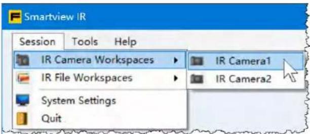
text_image
Smartview IR Session Tools Help IR Camera Workspaces IR File Workspaces System Settings Quit IR Camera1 IR Camera2- In the IR Camera window of the IR Camera Workspace interface, click Connect) in the upper right corner.
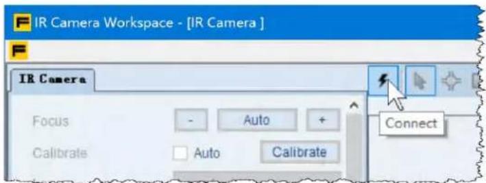
text_image
IR Camera Workspace - [IR Camera ] IR Camera Focus - Auto + Calibrate Auto Calibrate Connect- In the Connect dialog box, set Camera Type to zUSB. Then click OK button.
- Next, follow the instructions in the user manual for SmartView IR to view and record the fully-radiometric video stream in real time.
Import and Save Thermal Image Files
To import images captured by the Imager to a PC, use the removable memory card included with the system, or connect the Imager directly to the PC.
To transfer thermal image files to a PC using the removable memory card, use the card reader included with the system or a universal card reader, and copy the files to the appropriate folder on the PC.
The location of the thermal image file on the SD memory card: SD Card\00PdmIR\Gallery.
Note
When using a card reader, you may need to install the necessary drivers. Follow the instructions that came with the card reader.
To connect the Imager to a PC
- Turn off the visible light camera on the Imager. See Settings.

Storage & Save DC Camera

- Use the Type-C USB cable provided with the Product, connect the Imager to a PC by plugging the Type-C end into the Type-C interface on the bottom of the Imager and the Type-A end into the PC, as shown in Figure 33.
Note
Operation on the PC may vary slightly depending on its operating system, but the instructions are similar. See the specific information on the screen for operation.
- Open File Explorer and click This PC in the left column.
- In Devices and drives on the right side of File Explorer window, look for an icon of a multimedia device and the name of the Image below or next to it, for example, TIX1080CN#L25, as shown below.
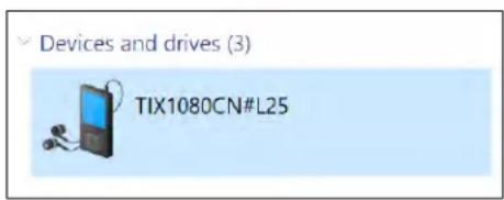
text_image
Devices and drives (3) TIX1080CN#L25- Double click the icon.
There can be 1 or 2 mobile storage devices, for example, SD card and Internal storage, that correspond to the external memory card and internal flash memory of the Imager, as shown below.
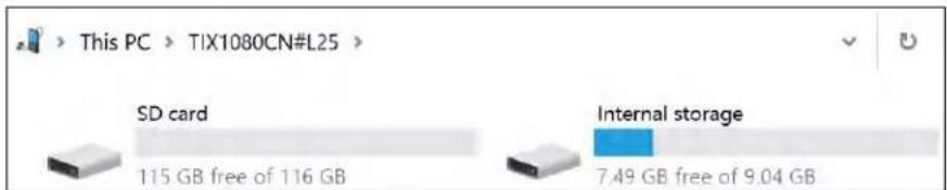
text_image
This PC > TIX1080CN#L25 > SD card 115 GB free of 116 GB Internal storage 7.49 GB free of 9.04 GB- Copy the thermal image files from the SD card or the Imager internal flash memory to a folder on your PC. You can create the target folder according to your standards.
The location of thermal image files in the SD card (for example): This PC\TIX1080CN#L25\SD Card\00PdmIR\Gallery.
The location of thermal image files in the internal memory is (for example): This PC\TIX1080CN#L25\ Internal storage\00PdmIR\Gallery.
Accessories
Table 19 is a list of the accessories available for the Imager.
Table 20. Optional Accessories
| Imager Model | Lens | Field of View (FOV) | Spatial Resolution (IFOV) | Minimum Focus Distance | Focal Length |
| TiX1000 Series | Standard lens | 25.0° x 19.0° | 0.43 mrad | 0.5 m | 39.6 mm |
| Wide-angle lens | 50.0° x 36.9° | 0.85 mrad | 0.1 m | 20.6 mm | |
| 2x telephoto lens | 12.0° x 9.1° | 0.20 mrad | 1.3 m | 81.3 mm | |
| 4x telephoto lens | 9.5° x 7.2° | 0.16 mrad | 3 m | 102.6 mm | |
| Macro lens | 50 μm | / | 97 mm | / | |
| TiX800 Series | Standard lens | 25° x 19° | 0.68 mrad | 0.5 m | 25 mm |
| Wide-angle lens | 50° x 39° | 1.36 mrad | 1 m | 13 mm | |
| 2x telephoto lens | 12° x 9° | 0.34 mrad | 2 m | 50 mm | |
| 4x telephoto lens | 8° x 6° | 0.22 mrad | 3 m | -77.4 mm | |
| Macro lens | 50 μm | / | 77.5 mm | / | |
| 20 μm | / | 9.4 mm | / |
Optional Lenses
Use optional telephoto and wide-angle lenses for more infrared inspection applications. For details on how to install or replace a lens, see Figure 34.

text_image
Diagram showing five sequential steps of a camera lens system with labeled components and directional arrows indicating motion.Figure 34. Change Lens
To change the optional lens:
- Push and hold the buckle on the side of the Imager lens cover.
- Rotate the lens cover counterclockwise.
- Remove the lens cover.
- Pick up the optional lens to be installed, press the buckle on the side of the lens, and align it with the lens mount of the Imager.
- Rotate the optional lens clockwise and the optional lens is installed when you hear a click.
Maintenance
There are no parts inside the Product requiring repair and maintenance and no special maintenance is needed. Only cleaning and lens care, battery replacement and battery charging are required.
Warning
To prevent eye damage and personal injury, do not open the Product. The laser beam is dangerous to eyes.
Have the Product repaired only through an approved technical service.
Clean the Product
Clean the case with damp cloth and weak soap solution. Do not use abrasives, isopropyl alcohol, or solvents to clean the case or lens.
Lens Care
Caution
To prevent damage to the infrared lens:
- Carefully clean the infrared lens. The lens has a delicate anti-reflective coating.
- Do not clean the lens too vigorously because this can damage the anti-reflective coating.
To clean the lens:
- Use a pressurized can of air or a dry nitrogen-ion gun, if available, to blow off the particulates from the lens surface.
- Soak a lint-free cloth in commercially available lens cleaning neutral solvent.
- Squeeze the cloth to remove excess liquid.
- Wipe the lens surface in a circular motion and discard the cloth.
- If needed, repeat with new lint-free cloth.
Battery Care
⚠ Warning
To prevent personal injury and for safe operation of the Product:
- Do not put battery cells and packs near heat or fire. Do not put in sunlight.
- Do not disassemble or crush battery cells and packs.
- Remove the battery to prevent battery leakage and damage to the Product if it is not used for an extended period.
- Connect the battery charger to the mains power outlet.
- Use only Fluke approved power adapters to charge the battery.
- Keep the battery pack clean and dry. Clean dirty connectors with dry, clean cloth.
Caution
To prevent damage, do not expose the Product to heat sources or high-temperature environments such as an unattended vehicle in the sun.
To get the best performance from the lithium-ion battery:
- Do not put the battery on the charger for more than 24 hours as reduced battery life may result.
- Charge the battery for at least two hours every six months for maximum battery life. When not in use, the battery will self-discharge in approximately six months. Batteries stored for long periods will need 2 to 10 charging cycles for full capacity.
Charge the Battery
Before you use the Imager for the first time, charge the battery for a minimum of two and one half hours.
To charge the battery:
- Push down the release button on the battery compartment cover.
- Open the battery compartment cover.
- Unlock the lock button in the battery compartment and take out the battery.
- Close the battery compartment cover.
- Put the removed lithium battery into the bays of the battery charger base.
- Put one or two lithium batteries into the bays of the charger base.
- Connect the power cable to the power socket on the back of the charger base.
- Connect the power cable plug to the power socket.
- When the battery is fully charged, unplug the power cable and place the charger in the carrying case.
Warning
Wipe off any water or moisture from the battery with clean, dry cloth before putting the battery into the Imager.
Note
Do not charge lithium batteries in an ambient temperature higher than 40^ C or lower than 0^ C. If the battery is charged under extreme temperatures, the capacity may be reduced.
Caution
Do not incinerate the Product and/or the battery.
Product Disposal
Dispose of the Product in a professional and environmentally appropriate manner:
- Delete personal data on the Product before disposal.
- Remove batteries that are not integrated into the electrical system before disposal and dispose of batteries separately.
- If this Product has an integral battery, put the entire Product in the electrical waste.
Radio Frequency
To view the Radio Frequency Data Class A Instruction Sheet, visit http://www.fluke.com/en-us/support and search for "Radio Frequency Data Class A".
TiX870, TiX875, TiX880, TiX885,
TiX875U, TiX885U, TiX1060, TiX1080
Users Manual
Specifications
| Model | TiX1060 | TiX1080 | TiX870 | TiX875 | TiX880 | TiX885 | TiX875U | TiX885U |
| Temperature | ||||||||
| Operating | -10 °C to 50 C | |||||||
| Storage | -40 °C to 70 °C (without battery) | |||||||
| Relative Humidity | <90 % RH, non-condensing | |||||||
| Altitude | ||||||||
| Operating 2000 m | ||||||||
| Storage 12000 m | ||||||||
| Screen | 5.5-inch OLED touchscreen, 100000:1 contrast, 170° visual range 1920x1080 pixels, 1080p UHD display | |||||||
| Power | ||||||||
| Battery | Li-ion battery, BP1000 (3 pcs) | |||||||
| Battery life | >3.5 hours continuous use time at 25 °C ambient | |||||||
| Battery charge time | 2.5 hours to full charge | |||||||
| Battery charge temperature | 0 °C to 40 °C | |||||||
| Battery charge mode | Ti SBC1K Battery Charger Base | |||||||
| Safety | IEC 61010-1: pollution degree 2 | |||||||
| Wireless | ||||||||
| Frequency | 2400 MHz to 2483.5 MHz | |||||||
| Output power | <100 mW | |||||||
| Laser | ||||||||
| Wavelength 650 nm | ||||||||
| Maximum output power | <1 mW | |||||||
| Electromagnetic Compatibility (EMC) | ||||||||
| International IEC 60326-1: Industrial Electromagnetic EnvironmentCISPR 11 Group 1, Class AGroup 1: Equipment has intentionally generated and/or uses conductively-coupled radio frequency energy that is necessary for the internal function of the equipment itself.Class A: Equipment is suitable for use in all establishments other than domestic and those directly connected to a low-voltage power supply network that supplies buildings used for domestic purposes. There may be potential difficulties in ensuring electromagnetic compatibility in other environments due to conducted and radiated disturbances.Caution: This equipment is not intended for use in residential environments and may not provide adequate protection to radio reception in such environments.Korea (KCC) Class A Equipment (Industrial Broadcasting & Communication EquipmentClass A: Equipment meets requirements for industrial electromagnetic wave equipment and the seller or user should take notice of it.This equipment is intended for use in business environments and not to be used in homes. | ||||||||
| Drop Test | 1 meter (with standard lens) | |||||||
| Dimensions (L x W x H) | 151 mm x 214 mm x92 mm | 148 mm x 204 mm x 86 mm | ||||||
| Weight (includes battery) | 1822 g 1550 g | |||||||
| Ingress Protection | IEC 60529-1: IP52 (with protective cover) | |||||||
| Tripod Mounting Base | UNC 1⁄4"-20 Standard Tripod Mounting Thread, which can be used to connect a tripod | |||||||
| Calibration Period | 2 years (assumes normal operation and aging) | |||||||
| Supported Languages | Simplified Chinese and English | |||||||
TiX870, TiX875, TiX880, TiX885, TiX875U, TiX885U, TiX1060, TiX1080
Users Manual
| Model | TiX1060 | TiX1080 | TiX870 | TiX875 | TiX880 | TiX885 | TiX875U | TiX885U |
| Temperature Measurement and Analysis | ||||||||
| Temperature Measurement Range | -40 °C to 700 °C (-40 °C to 150 °C; 0 °C to 350 °C; 0 °C to 700 °C) | |||||||
| Extended temperature range | 300°C to 2000°C | 1200 °C | 1200 °C | |||||
| Accuracy | ±1 °C or 1 % of rdg., whichever is greater @ -10 °C to 150 °C; ±2 °C or ±2 %, whichever is greater @ other temperature ranges | ±2 °C or ±2 % of rdg., whichever is greater | ||||||
| High/low temperature capture | Yes | |||||||
| Reference temperature compensation | Yes. The full-screen and measurement mark temperature are displayed as the difference between the actual temperature and the fixed temperature | |||||||
| Automatic temperature difference calculation | Calculation of the difference between measurement markers or between a measurement marker and the fixed TREF | |||||||
| Temperature measurement methods | The highest and lowest temperature can be set within an area, and the highest/lowest temperature point can be automatically located | |||||||
| Correction settings | Emissivity, Reflected Temperature, Humidity, Ambient Temperature, Test Distance, Transmittance | |||||||
| Full-screen emissivity correction | 0.01 to 1.00, built-in emissivity table | |||||||
| Area emissivity correction | Yes | |||||||
| Analysis in the Imager | Perform point, area, and line temperature analysis on saved images | |||||||
| Analysis software | SmartView IR | |||||||
| Supported languages | Simplified Chinese/English | |||||||
| Area Temperature Measurement | ||||||||
| Point | 10 | 20 | 10 | 20 | 10 | 20 | 10 | 20 |
| Temperature measurement region (Rectangle and circle) | 5 | 10 | 10 | 20 | 10 | 20 | 10 | 20 |
| Temperature measurement line | 10 | 20 | 10 | 20 | 10 | 20 | 10 | 20 |
| Image capture frequency | 13 Hz @ full window; 25 Hz @ 1/2 window | 9 Hz | 30 Hz | 9 Hz | 30 Hz | |||
| Detector type | Focal Plane Array (FPA), uncooled infrared detector | |||||||
| Detector pixel spacing | 17 μm | |||||||
| Detector resolution | 1024 x 768 | 640 x 480 | ||||||
| Total pixels | 786 432 | 307 200 | ||||||
| SuperResolution | 2048 x 1536 | N/A | 1280 x 960 | N/A | 1280 x 960 | |||
| Thermal sensitivity (NETD) | <30 mk @ 30 °C | <35 mK @ 30 °C | <30 mK @ 30 °C | <25 mK @ 30 °C | ||||
| Field of View (FOV) | 25° x 19° | 25° x 19° | ||||||
| Spatial resolution | 0.43 mrad | 0.68 mrad | ||||||
| Spectral response | 7 μm to 14 μm | |||||||
| Lens aperture | F 1.0 | |||||||
| Focus system | Auto/Manual | |||||||
| Lens recognition | Auto | |||||||
| Digital zoom (continuous zooming) | 1 to 35x | 1 to 25x | 1 to 35x | 1 to 25x | 1 to 35x | |||
TiX870, TiX875, TiX880, TiX885, TiX875U, TiX885U, TiX1060, TiX1080
Users Manual
| Model | TiX1060 | TiX1080 | TiX870 | TiX875 | TiX880 | TiX885 | TiX875U | TiX885U |
| Image Display | ||||||||
| Digital image enhancement | Yes | |||||||
| Settings for On-Screen Display (OSD) | Yes. Users can set OSD, such as the maximum, minimum, average, full-screen emissivity and reflected temperature | |||||||
| Settings for Information Display of Temperature Measurement Mark | Yes. Each temperature measurement marker can be set separately, displaying information such as emissivity of a temperature marker | |||||||
| Built-in digital camera | 5.0 MP, auto focus | |||||||
| LED torch/flashlight Yes | ||||||||
| Picture-in-Picture (PIP) | Yes | |||||||
| Standard palettes | 30 palettes (15 standard palettes, 15 inverted palettes) | |||||||
| Manual image adjustment | Yes | |||||||
| Auto image adjustment | Yes | |||||||
| Minimum temperature span (manual mode) | 2 °C | |||||||
| Minimum temperature span (auto mode) | 4 °C | |||||||
| Color alarm (Isotherm) | Yes | |||||||
| Automatically naming thermal images | QR code QR | code | N/A | QR code | QR code | N/A | QR code | |
| Voice annotation | Yes. 200 s of voice annotation for each image | |||||||
| Text annotation | Yes. Simplified Chinese/English/Numbers | |||||||
Thermal Imagers
Specifications
| Model | TiX1060 | TiX1080 | TiX870 | TiX875 | TiX880 | TiX885 | TiX875U | TiX885U |
| Visible image associated | Yes | |||||||
| Image Capture and Data Storage | ||||||||
| Image viewing | Thumbnail navigation and selection | |||||||
| Internal flash memory | Built-in 16 G flash memory | |||||||
| SD card | High-speed SD card, 128 GBCaution: Fluke recommends the memory card that is supplied with the Imager or available from Fluke. Fluke does not warrant the use or reliability of aftermarket memory cards of different brands or capacities. | |||||||
| IR image file format | Standard JPEG, including measurement data, which meets the data format verification requirements of the State Grid for Infrared Imagers | |||||||
| Fully-radiometric infrared video file format file format | .IS5 | N/A | .IS5 | N/A | .IS5 | N/A | ||
| Non-radiometric video file format. | .MP4 | N/A | .MP4 | N/A | .MP4 | N/A | ||
| Visible light images | Standard JPEG, automatically associated with thermal images | |||||||
| Audio | Yes | |||||||
| Transfer interface | Connect to the SmartView IR on a PC via USB, or connect to a display terminal via HDMI | |||||||
| Bluetooth transfer | Yes. The saved files can be transferred to a PC via Bluetooth. | |||||||
| GPS | Yes | N/A | Yes | N/A | Yes | |||
| Remote display viewing | Yes.View the Imager's thermal video stream on a PC or a display terminal | |||||||
| Remote control Operation | Yes. Through the Smart View IR | |||||||
| USB | USB 2.0. Transfer fully-radiometric thermal image video stream to a PC; read the Imager's internal flash memory data; read SD card data | |||||||
| Antenna | Internal | |||||||
TiX870, TiX875, TiX880, TiX885, TiX875U, TiX885U, TiX1060, TiX1080
Users Manual
| Model | TiX1060 | TiX1080 | TiX870 | TiX875 | TiX880 | TiX885 | TiX875U | TiX885U |
| Fully-radiometric infrared video recording | Recorded into the Imager or a PC | N/A | Recorded into the Imager or a PC | N/A | Recorded into the Imager or a PC | N/A | ||
| Fully-radiometric infrared video recording (frame rate adjustable) | To the Imager: 1 Hz to 7 HzTo a PC: 12 Hz | N/A | 1 Hz to 12 Hz | N/A | 1 Hz to 12 Hz | N/A | ||
| Fully-radiometric infrared video streaming | USB 2.0 | N/A | USB 2.0 | N/A | USB 2.0 | N/A | ||
| Non-radiometric infrared video streaming | Transfer via HDMI | |||||||
| Video output Digital video output | ||||||||
| Auto capture | Interval of 1 s to 60 min 59 s | |||||||