EonStor GSe 4090 - NAS Infortrend - Free user manual and instructions
Find the device manual for free EonStor GSe 4090 Infortrend in PDF.

User questions about EonStor GSe 4090 Infortrend
0 question about this device. Answer the ones you know or ask your own.
Ask a new question about this device
Download the instructions for your NAS in PDF format for free! Find your manual EonStor GSe 4090 - Infortrend and take your electronic device back in hand. On this page are published all the documents necessary for the use of your device. EonStor GSe 4090 by Infortrend.
USER MANUAL EonStor GSe 4090 Infortrend
Expansion Enclosure Guide
Version: 8.5
Updated: October 2022
Abstract:
This guide contains instructions and system limitations for adding expansion enclosures to Infortrend storage system without affecting its existing storage operations.
ContentsContents 2
Introduction....3
Overview of Maximum Drives 3
Hybrid Expansion Enclosures 4
Expansion Enclosure Number 4
Expansion Enclosure Connections 6
SAS 12 Gb/s Storage System....6
SAS 6 Gb/s Storage System....8
Model Classification (Single and Redundant) 9
Expansion Enclosure On-line Expanding....10
-
Setting the expansion enclosure ID .... 10
-
Installing the newly-added expansion enclosure....10
-
Reconnecting the redundant SAS path (for redundant models only).... 11
-
Connecting new SAS cable 11
-
Turning on the newly-added expansion enclosure 11
-
Installing the newly added drives 12
EonStor DS 1000/2000/3000 & GS/GSe 1000 SAS 6Gb/s Model Expansion Table ...... 13
Previous G7/G7i Model Expansion Table....14
Previous G6 Model Expansion Table.... 15
Introduction
Infortrend storage systems are made of high quality and durable components based on a high-scalable hardware design, providing support in terms of scalability and upgradeability. You also have the option to expand your storage system's capacity with infortrend's expansion enclosures in different form factors, allowing you more storage and provide quicker and more efficient storage services without downtime.
The sections in this chapter list the expansion rules that you must follow when configuring the expansion enclosures with SAS 12 Gb/s drive-side models.
Overview of Maximum Drives
Infortrend provides various form factors that you can select for storage systems and expansion enclosures. The maximum number of drives can be calculated based on the different models. Infortrend always uses SAS expansion technology to implement massive drive scalability. Most of the products have onboard SAS ports to connect expansion enclosures and some models support SAS expansion board to connect more expansion systems.
Take a look at the table below for Infortrend's products, the maximum number of drives, and their supported interfaces:
| Hybrid SAS Interface | Storage System Drives | On-board SAS Ports | SAS Expansion Board | Maximum Drives |
| EonStor DS Family (SAS 12Gb/s) | 448 within 15 mixed expansion enclosures (JB3012/IB3016/JB30248/IB3025B/JB3060(L) /JB2012/IB2016/IB2024/IB2036/JB2060) | N/A | 448 | |
| EonStor GS 100.0 Gen2 EonStor GS 100.0B Gen2 EonStor GSe 100.0 Gen2 | 448 within 15 mixed expansion enclosures | N/A | 448 | |
| EonStor GS 200.0/3000/4000 EonStor GSe 200.0/3000 EonStor GSe 2000/3000 | 448 within 15 mixed expansion enclosures | 448 within 15 mixed expansion enclosures | 396 (A48 + A48) | |
| EonStor GS 300.0/4000 Gen2 | 448 within 15 mixed | 448 within 15 mixed | ||
| EonServ for AI (EVi) 5016 | 16 bay | 224 with 14 x JB 316 or 420 with 7 x JB 360(L) | N/A | 436 (16 + 420) |
| Storage Server | Storage System Drives | On-board SAS Ports | SAS Expansion Board | Maximum Drives |
| EonServ 4012 | 12 bay | N/A | 168 with 14 x JB 312 or 300 with 5 x JB 360(L) | 312 (12 + 300) |
| EonServ 4016 | 16 bay | N/A | 224 with 14 x JB 316 or 300 with 5 x JB 360(L) | 316 (16 + 300) |
| EonServ 5012 Gen 1/Gen2 | 12 bay | 168 with 14 x JB 312 or 300 with 7 x JB 360(L) | N/A | 432 (12 + 420) |
| EonServ 5016 Gen 1/ Gen2 | 16 bay | 224 with 14 x JB 316 or 300 with 7 x JB 360(L) | N/A | 436 (16 + 420) |
| EonServ 7012 | 12 bay | 168 with 14 x JB 312 or 420 with 7 x JB 360(L) | N/A | 432 (12 + 420) |
| EonServ 7016 | 16 bay | 224 with 14 x JB 316 or 420 with 7 x JB 360(L) | N/A | 436 (16 + 420) |
Table 1: Maximum Drives of Current Models
Hybrid Expansion Enclosures
Infortrend allows some models to support hybrid expansion enclosure connections. The onboard SAS expansion port (either dual or single port) supports up to 448 drives for each expansion chain, which is limited by the SAS chip used. Infortrend also offers SAS 12 Gb/s expansion board for some models, which uses the same SAS chip as the onboard expansion ports. You can use twice the supported number of drives of up to 896 (1792 for EonStor GS/GSc 5000) by cascading the second expansion chain via the expansion host boards. Do note that not every model supports hybrid expansion enclosures configuration.
For the supported number of drives, see section Overview of Maximum Drives.
Systems that support hybrid expansion enclosures:
● EonStor DS/GS/GSe family (12 Gb/s SAS drive-side models)
- EonStor GSc family
● EonStor GSe Pro 3000 series
Systems that do not support hybrid expansion enclosures:
EonStor DS/GS/GSe family (6 Gb/s SAS drive-side models)
● EonStor GSa Gen1 family
- EonStor GSi family
- EonServ family
● EonServ for AI family
● EonStor GSe Pro 100/200/1000 series
Expansion Enclosure Number
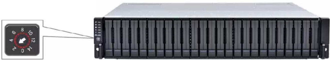
Before setting up an extra expansion enclosure to an existing configuration, you must set the rotary ID switch using a flat-blade screwdriver. Do note that each expansion enclosure must have a unique ID within an expansion chain. Currently, the expansion enclosure's rotary ID switch is numbered from 1 to 15, which means you can only connect up to 15 expansion enclosures per expansion chain.
IMPORTANT!
To prevent any ID conflicts, ensure that you set a unique ID to each expansion enclosure when connecting in a multi-array environment.

natural_image
Front view of a rack-mounted server unit with a dial indicator (no text or symbols on the device itself)Figure 1: Expansion Enclosures ID switch
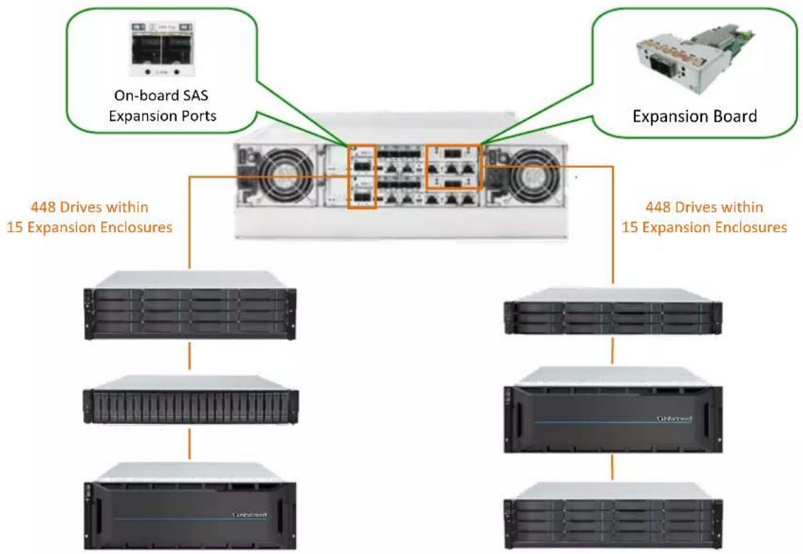
flowchart
graph TD
    A["On-board SAS Expansion Ports"] --> B["448 Drives within 15 Expansion Enclosures"]
    C["Expansion Board"] --> B
    B --> D["448 Drives within 15 Expansion Enclosures"]
    D --> E["Server Rack"]
    D --> F["Server Rack"]
    D --> G["Server Rack"]
Figure 2: Hybrid Expansion Enclosures
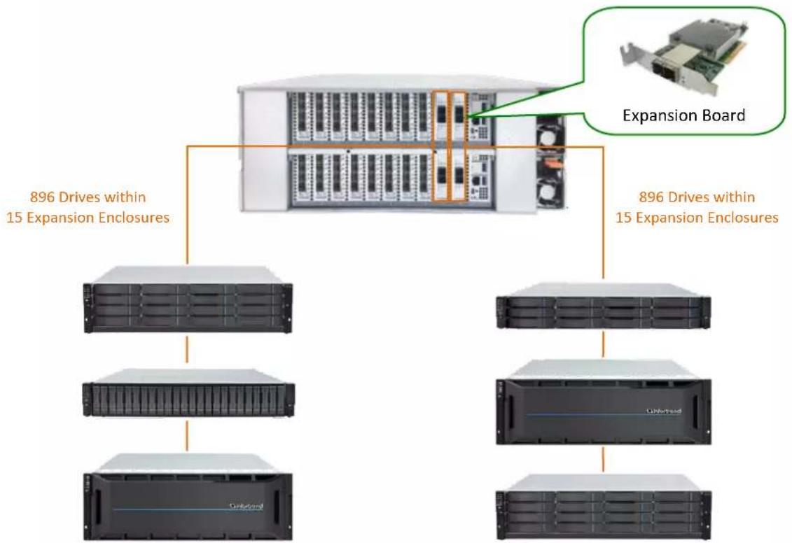
flowchart
graph TD
    A["896 Drives within 15 Expansion Enclosures"] --> B["Server Rack"]
    A --> C["Server Rack"]
    A --> D["Server Rack"]
    A --> E["Server Rack"]
    F["Expansion Board"] --> G["Server Rack"]
    F --> H["Server Rack"]
    F --> I["Server Rack"]
Figure 3: Hybrid Expansion Enclosures of EonStor GS/GSc 5000
Expansion Enclosure Connections
The sections in this chapter discuss the connections between expansions and storage systems with SAS 6 Gb/s and SAS 12 Gb/s technologies. Since the SAS drive-side protocol technology has been upgraded from SAS 6 Gb/s to SAS 12 Gb/s, the operating storage system can use different SAS protocol for expansion.
SAS 12 Gb/s Storage System
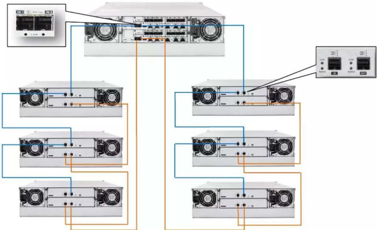
For Infortrend storage systems with SAS 12 Gb/s drive-side, the onboard SAS expansion ports are marked as IN.

natural_image
Front view of a server rack with multiple ports and ventilation fans (no visible text or labels)Figure 4: SAS 12 Gb/s Storage System Onboard Expansion Port
For any type of expansion enclosure, connect a SAS cable (blue) from the primary controller's SAS expansion port of the storage system to the primary controller's OUT SAS port of the first expansion enclosure.
To configure the redundant paths in two daisy-chain topology, connect a SAS cable (orange) from the second controller's SAS expansion port of the storage system to the second controller's SAS OUT port of the last expansion enclosure. Basic connection rule when connecting systems in this connection type is IN to OUT, from the last expansion enclosure to the first expansion enclosure.

natural_image
Four-panel diagram of a server rack with multiple drive units and connected cables (no text or labels visible)Figure 5: Connecting single-controller expansions using the onboard SAS 12 Gb/s expansion ports.
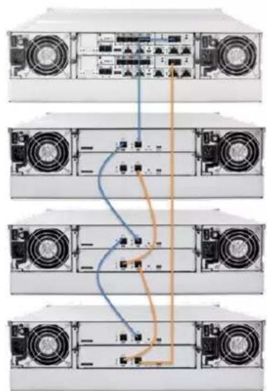
natural_image
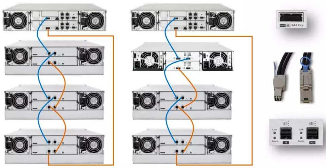
Diagram of five server rack units with connected cables, showing front and rear views (no text or labels)Figure 6: Connecting dual-controller expansions using host board's SAS 12Gb/s expansion ports.
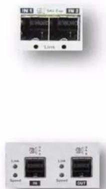
text_image
IN1 SAD Exp IN2 IN1 SAD Exp IN2 Link Speed IN SAD Exp IN2 Speed OUT
text_image
Diagram showing network topology with labeled components including server, drive, and network portsFigure 7: Connecting single-controller expansions using the onboard SAS 12Gb/s expansion ports
flowchart
graph TD
    A["Server Rack"] --> B["AT&T Ethernet"]
    A --> C["AT&T Ethernet"]
    A --> D["AT&T Ethernet"]
    A --> E["AT&T Ethernet"]
    A --> F["AT&T Ethernet"]
    A --> G["AT&T Ethernet"]
    A --> H["AT&T Ethernet"]
    A --> I["AT&T Ethernet"]
    A --> J["AT&T Ethernet"]
    A --> K["AT&T Ethernet"]
    A --> L["AT&T Ethernet"]
    A --> M["AT&T Ethernet"]
    A --> N["AT&T Ethernet"]
    A --> O["AT&T Ethernet"]
    A --> P["AT&T Ethernet"]
    A --> Q["AT&T Ethernet"]
    A --> R["AT&T Ethernet"]
    A --> S["AT&T Ethernet"]
    A --> T["AT&T Ethernet"]
    A --> U["AT&T Ethernet"]
    A --> V["AT&T Ethernet"]
    A --> W["AT&T Ethernet"]
    A --> X["AT&T Ethernet"]
    A --> Y["AT&T Ethernet"]
    A --> Z["AT&T Ethernet"]
    A --> AA["AT&T Ethernet"]
    A --> AB["AT&T Ethernet"]
    A --> AC["AT&T Ethernet"]
    A --> AD["AT&T Ethernet"]
    A --> AE["AT&T Ethernet"]
    A --> AF["AT&T Ethernet"]
    A --> AG["AT&T Ethernet"]
    A --> AH["AT&T Ethernet"]
    A --> AI["AT&T Ethernet"]
    A --> AJ["AT&T Ethernet"]
    A --> AK["AT&T Ethernet"]
    A --> AL["AT&T Ethernet"]
    A --> AM["AT&T Ethernet"]
    A --> AN["AT&T Ethernet"]
    A --> AO["AT&T Ethernet"]
    A --> AP["AT&T Ethernet"]
    A --> AQ["AT&T Ethernet"]
    A --> AR["AT&T Ethernet"]
    A --> AS["AT&T Ethernet"]
    A --> AT["AT&T Ethernet"]
    A --> AU["AT&T Ethernet"]
    A --> AV["AT&T Ethernet"]
    A --> AW["AT&T Ethernet"]
    A --> AX["AT&T Ethernet"]
    A --> AY["AT&T Ethernet"]
    A --> AZ["AT&T Ethernet"]
    A --> BA["AT&T Ethernet"]
    A --> BB["AT&T Ethernet"]
    A --> BC["AT&T Ethernet"]
    A --> BD["AT&T Ethernet"]
    A --> BE["AT&T Ethernet"]
    A --> BF["AT&T Ethernet"]
    A --> BG["AT&T Ethernet"]
    A --> BH["AT&T Ethernet"]
    A --> BI["AT&T Ethernet"]
    A --> BJ["AT&T Ethernet"]
    A --> BK["AT&T Ethernet"]
    A --> BL["AT&T Ethernet"]
    A --> BM["AT&T Ethernet"]
    A --> BN["AT&T Ethernet"]
    A --> BO["AT&T Ethernet"]
    A --> BP["AT&T Ethernet"]
    A --> BQ["AT&T Ethernet"]
    A --> BR["AT&T Ethernet"]
    A --> BS["AT&T Ethernet"]
    A --> BT["AT&T Ethernet"]
    A --> BU["AT&T Ethernet"]
    A --> BV["AT&T Ethernet"]
    A --> BW["AT&T Ethernet"]
    A --> BX["AT&T Ethernet"]
    A --> BY["AT&T Ethernet"]
    A --> BZ["AT&T Ethernet"]
    A --> CA["AT&T Ethernet"]
    A --> CB["AT&T Ethernet"]
    A --> CC["AT&T Ethernet"]
    A --> CD["AT&T Ethernet"]
    A --> CE["AT&T Ethernet"]
    A --> CF["AT&T Ethernet"]
    A --> CG["AT&T Ethernet"]
    A --> CH["AT&T Ethernet"]
    A --> CI["AT&T Ethernet"]
    A --> CJ["AT&T Ethernet"]
    A --> CK["AT&T Ethernet"]
    A --> CL["AT&T Ethernet"]
    A --> CM["AT&T Ethernet"]
    A --> CN["AT&T Ethernet"]
    A --> CO["AT&T Ethernet"]
    A --> CP["AT&T Ethernet"]
    A --> CQ["AT&T Ethernet"]
    A --> CR["AT&T Ethernet"]
    A --> CS["AT&T Ethernet"]
    A --> CT["AT&T Ethernet"]
    A --> CU["AT&T Ethernet"]
    A --> CV["AT&T Ethernet"]
    A --> CW["AT&T Ethernet"]
    A --> CX["AT&T Ethernet"]
    A --> CY["AT&T Ethernet"]
    A --> CZ["AT&T Ethernet"]
    A --> DA["AT&T Ethernet"]
    A --> DB["AT&T Ethernet"]
    A --> DC["AT&T Ethernet"]
    A --> DD["AT&T Ethernet"]
    A --> DE["AT&T Ethernet"]
    A --> DF["AT&T Ethernet"]
    A --> DG["AT&T Ethernet"]
    A --> DH["AT&T Ethernet"]
    A --> DI["AT&T Ethernet"]
    A --> DJ["AT&T Ethernet"]
    A --> DK["AT&T Ethernet"]
    A --> DL["AT&T Ethernet"]
    A --> DV["AT&T Ethernet"]
    A --> DW["AT&T Ethernet"]
    A --> DX["X"] & DX["V"] & DX["W"] & DX["X"] & DX["Y"] & DX["Z"] & DX["X"] & DX["Y"] & DX["X"] & DX["X"] & DX["X"] & DX["X"] & DX["X"] & DX["X"] & DX["X"] & DX["X"] & DX["X"] & DX["X"] & DX["X"] & DX["X"] & DX["X"] & DX["X"] & DX["X"] & DX["X"] & DX["X"] & DX["X"] & DX["X"] & DX["X"] & DX["X"] & DX["X"] & DX["X"] & DX["X"] & DX["X"] & DXX & DXY & DXYZ & DXZY & DXZYW & DXZYW & DXZYW & DXZYW & DXZYW & DXZYW & DXZYW & DXZYW & DXZYW & DXZYW & DXZYW & DXZYW & DXZYW & DXZYW & DXZYW & DXZYW & DXZYW & DXZYW & DXZYW & DXZYW & DXZYW & DXZYW & DXZYW & DXZYW & DXZYW & DXZYY & DXZYY & DXZYY & DXZYY & DXZYY & DXZYY & DXZYY & DXZYY & DXZYY & DXZYY & DXZYY & DXZYY & DXZYY & DXZYY & DXZYY & DXZYY & DXZYY & DXZYY & DXZYY & DXZYY & DXZYY & DXZYY & DXZYY & DXZYY & DXZYY & DXZYV & DXZYV & DXZYV & DXZYV & DXZYV & DXZYV & DXZYV & DXZYV & DXZYV & DXZYV & DXZYV & DXZYV & DXZYV & DXZYV & DXZYV & DXZYV & DXZYV & DXZYV & DXZYV & DXZYV & DXZYV & DXZYV & DXZYV & DXZYV & DXZYV & DXZY V & DXZY V & DXZY V & DXZY V & DXZY V & DXZY V & DXZY V & DXZY V & DXZY V & DXZY V & DXZY V & DXZY V & DXZY V & DXZY V &DXCY&DXCY&DXCY&DXCY&DXCY&DXCY&DXCY&DXCY&DXCY&DXCY&DXCY&DXCY&DXCY&DXCY&DXCY&DXCY&DXCY&DXCY&DXCY&DXCY&DXCY&DXCY&DXCY&DXCY&DXCY&DXCY&DXCY&DXCY&DXCY&DXCY&DXCY&DXCY&DXCY&DXCY&DWG&DWG&DWG&DWG&DWG&DWG&DWG&DWG&DWG&DWG&DWG&DWG&DWG&DWG&DWG&DWG&DWG&DWG&DWG&DWG&DWG&DWG&DWG&DWG&DWG&DWG&DWG&DWG&DWG&DWG&DWG&DWG&DWG&DWG
Figure 8: Connecting dual-controller expansions using the onboard SAS 12Gb/s expansion ports
SAS 6 Gb/s Storage System
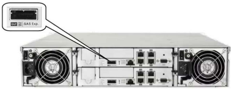
For SAS 6 Gb/s drive-side storage system, the SAS expansion ports are marked as OUT.
text_image
SAS Exp.Figure 9: SAS 6 Gb/s Storage System Onboard Expansion Port
For any type of expansion enclosure, attach a SAS cable (blue) from the primary controller's SAS OUT port of the storage system to the primary controller's IN SAS port of the expansion enclosure.
To ensure redundancy in two daisy-chain topology, connect a SAS cable (orange) from the second controller's SAS expansion port of the storage system to the second controller's IN SAS port of the last expansion enclosure. Basic connection rule when connecting systems in this connection type is OUT to IN, from the last expansion enclosure to the first expansion enclosure.
flowchart
graph TD
    subgraph Server 1
        A["Server 1"] --> B["Server 2"]
        C["Server 3"] --> D["Server 4"]
        E["Server 5"] --> F["Server 6"]
        G["Server 7"] --> H["Server 8"]
    end

    subgraph Server 2
        I["Server 1"] --> J["Server 2"]
        K["Server 3"] --> L["Server 4"]
        M["Server 5"] --> N["Server 6"]
        O["Server 7"] --> P["Server 8"]
    end

    subgraph SAS_Exp
        Q["SAS_Exp"] --> R["Device"]
        S["Switch"] --> T["Link"]
        U["Speed"] --> V["OK"]
        W["Speed"] --> X["OK"]
    end

    style Server 1 fill:#f9f,stroke:#333
    style Server 2 fill:#f9f,stroke:#333
    style SAS_Exp fill:#ccf,stroke:#333
Figure 10: SAS 6 Gb/s Storage System Expansion Connection
NOTE:
- SAS 6 Gb/s to 12 Gb/s cables are required for SAS 12 Gb/s expansion enclosure connection.
- Currently this configuration is only supported by the model that is newer than EonStor DS 1000. For G6 and G7/G7i models, please refer to Previous G7/G7i Model Expansion Table and Previous G6 Model Expansion Table.
Model Classification (Single and Redundant)
Infortrend products, especially the high-availability models, are also classified by the number of controllers: single and redundant. Redundant storage models are expandable via the redundant expansion enclosure. Single storage models, on the other hand, are expandable via the single expansion enclosures. All single models of storage and expansion enclosures are identified by two letters: S and G. G models are not upgradeable to redundant (R) models, while S models are upgradeable to redundant (R) models by installing a second S model controller. Take note that not every product supports S model.
For more information, refer to the table below:
| High Availability Models | Single Model | Redundant Model | Upgradable | |
| EonStor DS 1000/2000 | G Model | R Model | No | |
| EonStor DS 3000 | DS 3024/3024B | S Model | R Model | Yes |
| DS 3012/3016 | G Model | R Model | No | |
| EonStor DS 4000 | DS 4024/4024B | S Model | R Model | Yes |
| DS 4016 | S & G Model | R Model | Yes(No for G Model) | |
| EonStor GS 2000/3000/4000EonStor GS 1000/3000/4000 Gen2EonStor GSc 2000/3000EonStor GSa 2000/3000(Except 4U60 form factor) | S Model | R Model | Yes | |
| EonStor GS 3060EonStor GSc 3060 | G Model | R Model | No | |
| EonStor GS 5000EonStor GSc 5000EonStor GSa 5000 | N/A | R Model | N/A | |
| JB 3000(Except 4U60 form factor) | S Model | R Model | Yes | |
| JB 3060 | G Model | R Model | No | |
| Single Models | Single Model | Redundant Model | Upgradable | |
| EonStor GSe Family | G Model | N/A | N/A | |
| EonStor GSe Pro Family | G Model | N/A | N/A | |
| EonStor GSi Family | G Model | N/A | N/A | |
| EonServ Family | G Model | N/A | N/A | |
| EonServ for AI Family | G Model | N/A | N/A | |
| JB Pro 200 | G Model | N/A | N/A | |
| JB 300 | G Model | N/A | N/A | |
Table 2: Single and Redundant Models

natural_image
Two views of a server rack showing front and rear ports with ventilation grilles, one with a red arrow indicating transformation (no text or symbols visible)Figure 11: Upgrade from S Model to R Model
Expansion Enclosure On-line Expanding
This chapter details the steps of adding expansion enclosures to an already present storage system setup.

flowchart
graph LR
    A["Server Rack"] --> B["Storage System"]
    B --> C["Expansion enclosure 1"]
    C --> D["Expansion enclosure 2"]
    D --> E["Expansion enclosure 3 (Newly added)"]
Figure 12: Adding an expansion enclosure
1. Setting the expansion enclosure ID
The expansion enclosure ID is located at the front panel of the expansion enclosure. When setting expansion IDs, always set them in order: Set the first expansion to 1, the second expansion ID in 2, and so on. The newly-added expansion enclosures must be connected after the current setup's last expansion enclosure. Do take note that the enclosure IDs must be different from each other.
natural_image
Front view of a rack-mounted server unit with a dial indicator (no text or symbols on the device body)Figure 13: Expansion enclosure ID
2. Installing the newly-added expansion enclosure
Due to the expansion enclosure's heavy weight, we recommend you to install the hard drives to the expansion enclosure after the enclosure is already installed to the rack. After the ID assignment and installation of the expansion enclosures to the rack, you can now connect the added expansion enclosures to the current system assembly via SAS cables.
In connecting the newly-added enclosures, ensure that the SAS cables are long enough to reach between SAS ports. The longest cable is used to connect the storage system and the last expansion enclosure. In some cases, the expansion enclosures are not directly installed on top or bottom of the storage system, so the cabling routes may vary. In most cases, at least one long SAS cable is required.
3. Reconnecting the redundant SAS path (for redundant models only)
Unplug the SAS cable from the current last expansion controller (see dotted orange connection in Figure 9), then connect it to the SAS port of newly-added last expansion's second controller (see longest orange cable connection in Figure 9). A longer SAS cable may be required.
This step involves disconnecting one of the SAS cables, so critical events on storage system such as reports of drive-side redundant path failure are expected. You will get notification events from the management GUI, LCD panel, LEDs, and other means of notification alerts.
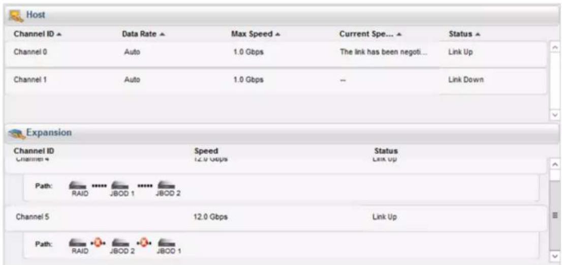
text_image
Host Channel ID ▲ Data Rate ▲ Max Speed ▲ Current Spe... ▲ Status ▲ Channel 0 Auto 1.0 Gbps The link has been negoti... Link Up Channel 1 Auto 1.0 Gbps -- Link Down Expansion Channel ID Speed Status Channel 4 12.0 Gbps Link Up Path: RAID JBOD 1 JBOD 2 Channel 5 12.0 Gbps Link Up Path: RAID JBOD 2 JBOD 1Figure 14: Redundant path failure of expansion enclosures in SANWatch
4. Connecting new SAS cable
Connect new SAS cables (see black connection) from the current last expansion to the newly-added expansion enclosure. Ensure to follow the SAS connection's IN to OUT rule described in Expansion Enclosure Connections.
NOTE:
The sample diagram is only for SAS 12 Gb/s storage system.
5. Turning on the newly-added expansion enclosure
Press the power button to turn on the expansion enclosure, then wait for the storage management GUI to display the additional expansion enclosure. Once the added subsystem is successfully working with the system assembly, the storage system's status on the management, GUI, LCD panel, LED panel, and other status features are back to normal.
Do take note that adding a newly-added expansion enclosure also sets the Hot-Add feature, which may cause delay or pause for about 10-20 seconds on the host I/O. The delay/pause time may vary depending on the operating system, drivers, and other factors.
6. Installing the newly added drives
We recommend you to install the drives into the newly-added expansion enclosure after the enclosure is successfully recognized by the storage system. After installing the drives to the enclosure, check the drives' status in the storage management GUI. Once the drives appeared on the GUI, you can already use them in storage provisioning. For more details, refer to the software manual.
IMPORTANT!
If SANWatch or Embedded RAIDWatch is used as a management tool for DS family, you must reload the mentioned management tool after connecting the new expansion enclosure. If the management tool does not display the newly-added enclosures, click Data Reload from the upper-right corner of the GUI to refresh the screen.
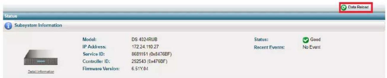
text_image
Status Subsystem Information Model: DS 4024RUB Status: Good IP Address: 172.24.110.27 Recent Events: No Event Service ID: 8681151 (0x8476BF) Controller ID: 292543 (0x476BF) Firmware Version: 6.51Y.04Figure 15: Data Reload button on Embedded RAIDWatch
EonStor DS 1000/2000/3000 & GS/GSe 1000
SAS 6Gb/s Model Expansion Table
| Model Name | Expansion Enclosure |
| DS1012 (SAS 6Gb/s) | 14 x JB 2012 / JB 3012 |
| DS2012 (SAS 6Gb/s) | 5 x JB 2048 |
| DS3012 (SAS 6Gb/s) | 5 x JB 2060(L) / JB 3060(L) |
| DS1016 (SAS 6Gb/s) | 14 x JB 2016 / JB 3016 |
| DS2016 (SAS 6Gb/s) | 5 x JB 2048 |
| DS3016 (SAS 6Gb/s) | 5 x JB 2060(L) / JB 3060(L) |
| DS1024 (SAS 6Gb/s) | 14 x JB 2016 / JB 3016 |
| DS2024 (SAS 6Gb/s) | 5 x JB 2048 |
| DS3024 (SAS 6Gb/s) | 5 x JB 2060(L) / JB 3060(L) |
| DS1024B (SAS 6Gb/s) | 14 x JB 2024B / JB 3024B |
| DS2024B (SAS 6Gb/s) | 5 x JB 2048 |
| DS3024B (SAS 6Gb/s) | 5 x JB 2060(L) / JB 3060(L) |
| DS1036B (SAS 6Gb/s) | 13 x JB 2024B / JB 3024B |
| 9 x JB 2036B | |
| 5 x JB 2060(L) / JB 3060(L) | |
| DS3048 (SAS 6Gb/s) | 5 x JB 2048 |
| 5 x JB 3060(L) | |
| DS3060 (SAS 6Gb/s) | 5 x JB 2060(L) / JB 3060(L) |
| GS1012 (SAS 6Gb/s) | 14 x JB 2012 / JB 3012 |
| GSe1012 (SAS 6Gb/s) | 5 x JB 2060(L) / JB 3060(L) |
| GS1016 (SAS 6Gb/s) | 14 x JB 2016 / JB 3016 |
| GSe1016 (SAS 6Gb/s) | 5 x JB 2060(L) / JB 3060(L) |
| GS1024 (SAS 6Gb/s) | 14 x JB 2016 / JB 3016 |
| 5 x JB 2060(L) / JB 3060(L) | |
| GS1024B (SAS 6Gb/s) | 14 x JB 2024B / JB 3024B |
| 5 x JB 2060(L) / JB 3060(L) |
Previous G7/G7i Model Expansion Table
| ESDS Model Name | Expansion Enclosure | Mixed Expansion Enclosure |
| B24F-R2852-6B24F-R2652-4 | 9 x ESDS B24S-J2000-R (3U) | |
| B24F-G2852-6B24F-G2652-4 | 9 x ESDS B24S-J2000-G (3U) | |
| S12F-R2651S12F-R2851S12E-R2251 | 8 x ESDS S12S-J2000-R/ JB 2012R (2U)6 x ESDS B24S-J2000-R (3U)4 x ESDS S48S-J2000-R (4U) | 5 x ESDS S12S-J2000-R/ JB 2012R + 3 x ESDS S48S-J2000-R2 x ESDS S12S-J2000-R/ JB 2012R + 4 x ESDS S48S-J2000-R |
| S12F-G2651S12F-G2851S12E-G2251 | 8 x ESDS S12S-J2000-G/ JB 2012S (2U)6 x ESDS B24S-J2000-G (3U)4 x ESDS S48S-J2000-G (4U) | 5 x ESDS S12S-J2000-G/ JB 2012S + 3 x ESDS S48S-J2000-G2 x ESDS S12S-J2000-G/ JB 2012S + 4 x ESDS S48S-J2000-G |
| S16F-R2652-4S16F-R2651S16F-R2852-6S16F-R2851S16E-R2251S16E-R2152-6S16S-R2250 | 8 x ESDS S16S-J2000-R/ JB 2016R (3U)6 x ESDS B24S-J2000-R (2U)4 x ESDS S48S-J2000-R (4U) | 5 x ESDS S16S-J2000-R/ JB 2016R + 3 x ESDS S48S-J2000-R2 x ESDS S16S-J2000-R/ JB 2016R + 4 x ESDS S48S-J2000-R |
| S16F-G2652-4S16F-G2651S16F-G2852-6S16FG2851S16E-G2251S16E-G2152-6S16S-G2250 | 8 x ESDS S16S-J2000-S/ JB 2016S (3U)6 x ESDS B24S-J2000-G (2U)4 x ESDS S48S-J2000-G (4U) | 5 x ESDS S16S-J2000-S/ JB 2016S + 3 x ESDS S48S-J2000-G2 x ESDS S16S-J2000-S/ JB 2016S + 4 x ESDS S48S-J2000-G |
| S24F-R2651S24F-R2851 | 8 x ESDS S16S-J2000-R/ JB 2016R (3U)6 x ESDS B24S-J2000-R (2U)4 x ESDS S48S-J2000-R (4U) | 5 x ESDS S16S-J2000-R/ JB 2016R + 2 x ESDS S48S-J2000-R1 x ESDS S16S-J2000-R/ JB 2016R + 4 x ESDS S48S-J2000-R |
| S24F-G2651S24F-G2851 | 8 x ESDS S16S-J2000-S/ JB 2016S (3U)6 x ESDS B24S-J2000-G (2U)4 x ESDS S48S-J2000-G (4U) | 5 x ESDS S16S-J2000-S/ JB 2016S + 2 x ESDS S48S-J2000-G1 x ESDS S16S-J2000-S/ JB 2016S + 4 x ESDS S48S-J2000-G |
| S48F-R2852-6S48F-R2652-4 | 4 x ESDS S48S-J2000-R | |
| S48F-G2852-6S48F-G2652-4 | 4 x ESDS S48S-J2000-G |
Previous G6 Model Expansion Table
| ESDS Model Name | Expansion Enclosure |
| B12F-G2840-4 | 6 x ESDS B12S-J2000-G (1U) |
| B12E-G2140-4 | 6 x ESDS S12S-J2000-G/ JB 2012S (2U) |
| B12S-G2240 | 6 x ESDS S16S-J2000-S/ JB 2016S |
| B12F-R2840-4 | 6 x ESDS B12S-J2000-R (1U) |
| B12E-R2140-4 | 6 x ESDS S12S-J2000-R/ JB 2012R (2U) |
| B12S-R2240 | 6 x ESDS S16S-J2000-R/ JB 2016R |
| B24F-G2840-4 | 5 x ESDS B24S-J2000-S (2U) |
| B24F-G2842-6 | 5 x ESDS S12S-J2000-G/ JB 2012S (2U) |
| B24E-G2142-6 | 5 x ESDS S16S-J2000-S/ JB 2016S |
| B24S-G2242-4 | JB 3012/JB 3016*1*2 |
| B24S-G2240 | |
| B24F-R2840-4 | 5 x ESDS B24S-J2000-R (2U) |
| B24F-R2842-6 | 5 x ESDS S12S-J2000-R/ JB 2012R (2U) |
| B24E-R2142-6 | 5 x ESDS S16S-J2000-R/ JB 2016R |
| B24S-R2242-4 | JB 3012/JB 3016*1*2 |
| B24S-R2240 | |
| S12F-S2840N | 6 x ESDS S12S-J2000-SN (2U) |
| S12F-R2840N | 6 x ESDS S12S-J2000-RN (2U) |
| S12F-G2840-4 | 6 x ESDS S12S-J2000-G/ JB 2012S (2U) |
| S12E-G2140-4 | JB 3012*1*2 |
| S12S-G2240-4 | |
| S12S-G2240 | |
| S12F-R2840-4 | 6 x ESDS S12S-J2000-R/ JB 2012R (2U) |
| S12E-R2140-4 | JB 3012*1*2 |
| S12S-R2240-4 | |
| S12S-R2240 | |
| S16F-G2840-4 | 6 x ESDS S16S-J2000-S/ JB 2016S |
| S16F-G2842-6 | JB 3016*1*2 |
| S16E-G2142-6 | |
| S16E-G2240 | |
| S16S-G2242-4 | |
| S16S-G2240-4 | |
| S16S-G2240 | |
| S16F-R2840-4 | 6 x ESDS S16S-J2000-R/ JB 2016R |
| S16F-R2842-6 | JB 3016*1*2 |
| S16E-R2142-6 | |
| S16E-R2240 | |
| S16S-R2242-4 | |
| S16S-R2240-4 | |
| S16S-R2240 | |
| S24F-G2840-4 | 5 x ESDS S16S-J2000-S/ JB 2016S |
| S24E-G2142-6 | JB 3016*1*2 |
| S24S-G2240-4 | |
| S24S-G2240 | |
| S24F-R2840-4 | 5 x ESDS S16S-J2000-R/ JB 2016R |
| S24F-R2842-6 | JB 3016*1*2 |
| S48F-G2842-6 | 4 x ESDS S48S-J2000-G (4U) |
| S48F-R2842-6 | 4 x ESDS S48S-J2000-R (4U) |
*1) This JBOD is only compatible with the RAID controller firmware v. 3.89J02 and SANWatch 3.0.e.100 or above.
*2) Tested only in a 1 RAID with 1 JBOD environment