M6-103EWS-Gw-C-3Gw - Speaker JL Audio - Free user manual and instructions
Find the device manual for free M6-103EWS-Gw-C-3Gw JL Audio in PDF.

User questions about M6-103EWS-Gw-C-3Gw JL Audio
0 question about this device. Answer the ones you know or ask your own.
Ask a new question about this device
Download the instructions for your Speaker in PDF format for free! Find your manual M6-103EWS-Gw-C-3Gw - JL Audio and take your electronic device back in hand. On this page are published all the documents necessary for the use of your device. M6-103EWS-Gw-C-3Gw by JL Audio.
USER MANUAL M6-103EWS-Gw-C-3Gw JL Audio
natural_image
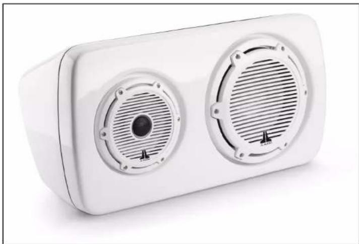
White rectangular electronic device with two circular vented outlets and a striped grille (no text or symbols visible)Thank you for choosing a JL Audio Enclosed Full-Range System for your sound system. These speakers have been designed and manufactured to exacting standards in order to ensure years of musical enjoyment.
For maximum performance, we strongly recommend that you have your new enclosed full-range system installed by your authorized JI. Audio dealer. Your authorized dealer has the training, expertise and installation equipment to ensure optimum performance from this product. Should you decide to install the enclosed full-range system yourself, please take the time to read this manual thoroughly so as to familiarize yourself with its installation requirements.
If you have any questions regarding the instructions in this manual, please contact your authorized JL Audio dealer for assistance.
JL AUDIO.
Ahead of the Curve
! IMPORTANT
If you choose to perform the installation yourself, it is absolutely vital that the enclosure be properly mounted according to these instructions. Failure to mount the enclosure properly presents two problems:
1) The sub-bass performance will suffer due to the movement of the enclosure caused by the force exerted by the woofer(s).
2) A loose enclosure presents a serious safety hazard in the event of a collision or other such accident.
INSTALLATION DIFFICULTY:

ESTIMATED TIME: 1 HOUR
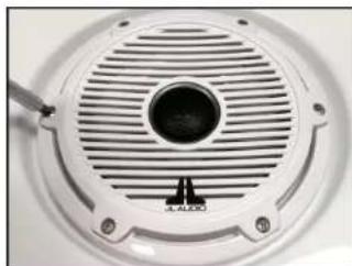
natural_image
Close-up of a white circular speaker grille with a central hole and screw base (no text or symbols visible)STEP 1
Remove the #8 - 18 x 1-1/4" Phillips Pan Head Screws and #8 Flat Washers from the speaker, and remove the speaker from the enclosure.
Remove the #10 - 16 x 1-5/8" Phillips Pan Head Screws and #10 Flat Washers from the subwoofer, and remove the subwoofer from the enclosure.

natural_image
Metal electrical switch with three red buttons and four metallic pins (no text or symbols visible)STEP 2
Make sure the Mounting Bracket and enclosure will fit in the desired installation position. Determine which side of the enclosure the Mounting Bracket will attach to based on the installation surface and orientation of the enclosure.
Be sure that the threaded studs will be accessible from inside the enclosure in order to secure the mounting hardware.

natural_image
Close-up of a white surface with two red circular markers, no visible text or symbolsSTEP 3
Align the Mounting Bracket Template on the enclosure as needed. Centering lines are available to aid in placement, if necessary.
Tape the Mounting Bracket Template in place.

natural_image
Hand drawing red circular marks on a white surface (no text or symbols visible)STEP 4
Mark the center locations of the two threaded studs (marked in RED) through the Mounting Bracket Template, onto the enclosure. Remove the template from the enclosure.
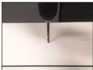
natural_image
Close-up of a precision tool tip interacting with a surface (no visible text or symbols)STEP 5
Using a 9/16" drill bit, carefully drill through the two marks made in the previous step.
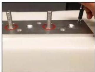
natural_image
Close-up of a metal workpiece with four bolts and a hand using a tool (no visible text or symbols)STEP 6
Position the Mounting Bracket onto the mounting surface as needed.
Six flush mount holes and three countersunk holes are available for a variety of applications.
Mark the center locations of the mounting holes as needed through the Mounting Bracket, onto the mounting surface. Remove the Mounting Bracket from the mounting surface.
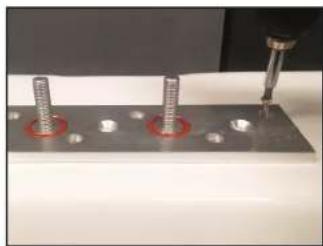
natural_image
Close-up of a mechanical assembly with three screws and a tool, no visible text or symbolsSTEP 7
Using the appropriate drill bit, drill pilot holes through the marks made in the previous step.
Permanently secure the Mounting Bracket to the mounting surface with the appropriate hardware (not included).

natural_image
Close-up of a metallic electrical connector with two red circular holes (no text or symbols visible)STEP 8
Be sure an orange 3/16" O-Ring is installed into each recess on the Mounting Bracket.
Place the enclosure onto the Mounting Bracket, allowing the two threaded studs on the bracket to pass through the holes drilled into the enclosure in Step 5.
natural_image
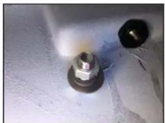
Close-up of two bolts on a textured surface (no visible text or symbols)STEP 9
From inside the enclosure, place a 1/2" Fender Washer, 1/2" Split Lock Washer, and 1/2" Hex Nut over each of the threaded studs on the Mounting Bracket, and firmly tighten.

natural_image
Close-up of a metal drill bit cutting into a small metallic tool (no visible text or symbols)STEP 10
Using an appropriately sized drill bit, drill a hole from the subwoofer enclosure into the speaker enclosure for the speaker cable.

natural_image
Close-up of a black plastic pipe inserted into a white cylindrical component, mounted on a white surface (no text or symbols visible)STEP 11
Unscrew the grommet, and pass two runs of speaker cable through it and into the enclosure.
Route one into the speaker enclosure.
natural_image
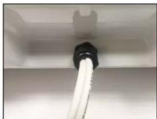
Close-up of a white hose inserted into a black pipe, mounted on a surface (no text or symbols visible)STEP 12
Tighten the grommet. From inside the enclosure, apply silicone adhesive (not included) around both speaker cable holes to prevent leaks.
natural_image
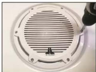
Close-up of a white circular vent with a screwdriver inserted, showing internal ridges and mounting holes (no text or symbols visible)STEP 13
Connect the speaker cable to the subwoofer and speaker, and reinstall both drivers in the desired orientation.
Secure the speaker with six #8 - 18 x 1-1/4" Phillips Pan Head Screws and #8 Flat Washers, and secure the subwoofer with six #10 - 16 x 1-5/8" Phillips Pan Head Screws and #10 Flat Washers.
CONGRATULATIONS!
natural_image
White rectangular electronic device with two circular vented fans and a central speaker grille (no text or symbols visible)INCLUDED HARDWARE:
(1) Mounting Bracket
(1) Mounting Bracket Template
(2) 3/16" O-Ring (pre-installed)
(2) 1/2" Flat Washer
(2) 1/2" Split Lock Washer
(2) 1/2" Hex Nut
(6) #8 - 18 x 1-1/4" Phillips Pan Head Screw
(6) #8 Flat Washer
(6) #10 - 16 x 1-5/8" Phillips Pan Head Screw
(6) #10 Flat Washer
JLAUDIO. How we play.
(954) 443-1100

www.jlaudio.com
All classifications are subject to change without so far. "Aids" will "How we play" be restructured from the Aids, but "Where of the Cows" and its respect is based on the following will be in.
JLA-SKU# 011543 - ver. 10.15.2019 · 10369 NORTH COMMERC - PARKWAY · MIRAMAR, L CHIDA · 33025 · USA

*011543*