
Evolution C5-570 - Loudspeaker JL Audio - Free user manual and instructions
Find the device manual for free Evolution C5-570 JL Audio in PDF.


| Product Type | Car Audio Coaxial Speaker |
| Model | Evolution C5-570 |
| Speaker Size | 5x7 inches / 6x8 inches |
| Impedance | 4 ohms |
| Power Handling (RMS) | 60 watts |
| Power Handling (Peak) | 180 watts |
| Frequency Response | 50 Hz - 22 kHz |
| Sensitivity | 91 dB @ 1W/1m |
| Cone Material | Polypropylene with mica |
| Tweeter Type | SWIVEL™ ceramic-coated soft dome |
| Mounting Depth | 2.38 inches (60.5 mm) |
| Mounting Hole Diameter | 5.5 x 7.5 inches (140 x 190 mm) |
| Weight | 2.2 lbs (1 kg) per speaker |
| Woofer Magnet | Ferrite |
| Tweeter Magnet | Neodymium |
| Includes | Grilles, mounting hardware, manual |
| Cleaning | Wipe with dry cloth; avoid liquids |
| Safety | Disconnect battery before installation; use in dry location |
| Spare Parts Availability | Contact JL Audio authorized dealer |
| Reparability | Professional service recommended for internal components |
Frequently Asked Questions - Evolution C5-570 JL Audio
User questions about Evolution C5-570 JL Audio
0 question about this device. Answer the ones you know or ask your own.
Ask a new question about this device
Download the instructions for your Loudspeaker in PDF format for free! Find your manual Evolution C5-570 - JL Audio and take your electronic device back in hand. On this page are published all the documents necessary for the use of your device. Evolution C5-570 by JL Audio.
USER MANUAL Evolution C5-570 JL Audio
5-inch x 7-inch (125 x 180 mm) 2-Way Component System

natural_image
Collection of automotive speaker components including a speaker, rear-mounted speaker, and two circular components (no text or symbols visible)Thank you for choosing a JL Audio Evolution™ C5 Component System for your automotive sound system.
These Evolution™ Speakers have been designed and manufactured to exacting standards in order to ensure years of musical enjoyment in your vehicle. For maximum performance, we highly recommend that you have your new speakers installed by an authorized JL Audio dealer. Your authorized dealer has the training, expertise and installation equipment to ensure optimum performance from this product. Should you decide to install the speakers yourself, please take the time to read this manual thoroughly so as to familiarize yourself with its installation requirements and setup procedures.
If you have any questions regarding the instructions in this manual or any aspect of your amplifier's operation, please contact your authorized JL Audio dealer for assistance. If you need further assistance, please call the JL Audio Technical Support Department at (954) 443-1100 during business hours.
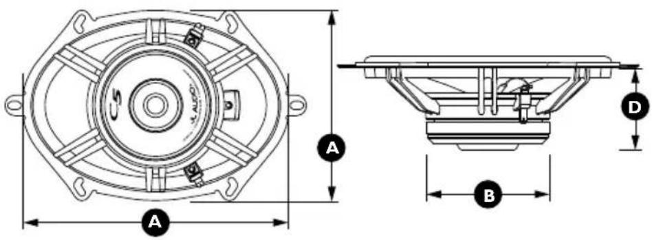
| Woofer Physical Dimensions | |
| Frame Outer Diameter (A) 5.47 x 7.68 in. / 139.0 x 195.1 mm | |
| Magnet Outer Diameter (B) 3.54 in. / 90.0 mm | |
| Mounting Hole Diameter (C) N/A | |
| Mounting Depth (D) 2.4 in. / 61 mm | |
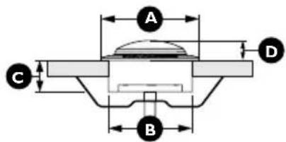

| Tweeter Fixture Physical Dimensions Flush-Mount Surface-Mount | ||
| Fixture Outer Diameter (A) 1.75 in. / 44.5 mm | 1.61 in. / 40.9 mm | |
| Fixture Mounting Hole Diameter (B) 1.50 in. / 38.1 mm N/A | ||
| Fixture Mounting Depth (C) 0.56 in. / 14.2 mm N/A | ||
| Tweeter Frontal Protrusion (D) | 0.36 in. / 9.1 mm | 0.87 in. / 22.1 mm |


| Crossover Network Physical Dimensions | |
| Height (A) 4.72 in. / 119.9 mm | |
| Width (B) 3.36 in. / 85.3 mm | |
| Depth (C) 1.44 in. / 36.6 mm | |
C5-570 sPeCIFICaTlons
Woofers: Cast Alloy Frame, Patented Elevated Frame Cooling (U.S. Patent #6,219,431 & #6,229,902), DMA-Optimized Motor System, Mineral-Filled Polypropylene Cone, Butyl Rubber Surround, 1-in. / 25 mm Voice Coil, Kapton® Former, Low-Profile, Symmetrical Roll Spider, Ferrite Magnet
Tweeters: 0.75 in. / 19 mm Silk Soft Dome RSR Variable-Angle Flush-Mount System, Ferrofluid Cooling and Damping, Neodymium Magnet
Crossover Networks: 2-way network with 1st order low-pass and 2nd order high-pass circuit, premium Mylar® capacitors, air-core inductors, 4-position adjustable tweeter output level, 3-position midrange presence control, Polyswitch tweeter protection
Continuous Power Handling: 75 Watts (RMS Method)
Peak Music Power: 225 Watts
Recommended Power Range: 25-150 Watts (RMS)
Frequency Response: 48 Hz - 25 KHz (± 3 dB)
Efficiency @ 1W/1m: 90.5 dB @ 1W/1m
Nominal Impedance: 4 ohms
Included Components and Parts:
- Two C5-570cw 5x7-inch (125 x 180 mm) Woofers
• Two C5-075ct 0.75-inch (19 mm) Tweeters
• Two C5-570-XO Crossover Networks
- Two Flush-Mount Tweeter Fixtures
- Two Surface-Mount Tweeter Fixtures
- Two Metal Spring Clips for Tweeter Fixtures
• Two Woofer Spacer Gaskets
- Two Self-Adhesive JL Audio Nameplates for Grilles
• Butyl Adhesive Putty for Woofer Grilles
• Twelve #8 x 1.25 inch (32 mm) Sheet Metal Screws
• Four #6 x 1-inch (25 mm) Sheet Metal Screws
- Two 1.18-inch (30 mm) Machine Screws
• Eight Mounting Clips for Woofer Mounting
- Two 6.4 mm Female Crimpable Connectors
• Four 4.7 mm Female Crimpable Connectors
- Two 2.8 mm Female Crimpable Connectors
• Four 2.8 mm Male Crimpable Connectors
• Twelve Crimpable Spade Connectors
GeTTInG sTarTeD
- Turn off the audio system. It is also advisable to disconnect the negative (−) terminal of your vehicle's battery whenever performing installation work.
- Before cutting, drilling or inserting any screw, check clearances on both sides of the planned mounting surface. Also check for any potential obstacles, such as window tracks and motors, wiring harnesses, etc. Check both sides of the vehicle, many vehicles are not symmetrical!
• Always wear protective eyewear.
CrossoVer neTworK InsTallaTlon
The crossover networks supplied with your C5 System should be installed in a dry location inside your vehicle. DO NOT INSTALL THEM INSIDE OF A DOOR! Doors often get wet on the inside, which can damage your crossover networks and could potentially damage your entire sound system. The crossovers can be screwed into a solid surface via two holes located under the protective cover of the case. To access these holes, simply squeeze the sides of the cover while gently pulling the cover away from the base. Make sure that your mounting location will not cause damage to wiring, fuel lines, brake lines or any other vital component of your vehicle. Once you have screwed the case in and made your connections, snap the protective cover back into place.
!! WARNING
It is absolutely vital that your component system is connected as shown in this manual. Failure to connect the system as shown may result in damage to your speakers which is NOT covered under warranty.
Do not substitute different crossover networks into your C5 System. Do not use crossover networks intended for different C5 models.
TweeTer ProTeCTlon
The C5 crossover networks are equipped with an advanced electronic tweeter protection circuit designed to minimize the possibility of tweeter failure. This electronic device monitors current going to the tweeter and will disconnect the tweeter from the signal when it senses overload. Should this occur while listening to the audio system, simply reduce the volume for a few seconds and the protection circuit will reset itself automatically.
CrossoVer neTworK aDJusTmenT
The crossover networks have been designed to allow tonal adjustments to the upper midrange response and tweeter level. These adjustments make it possible to fine-tune your system to suit your listening preferences and to compensate for various speaker mounting applications.
Amplifier Output

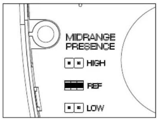
aDJusTaBle mIDranGe PresenCe
Your C5 crossover networks provide a unique midrange presence control, located under the cover. The midrange presence is selectable via a set of pins and allows for three settings. These settings affect the amplitude of the upper midrange response of the C5 component woofer. We recommend that you begin your listening in the “REF” (Reference) and adjust up or down as needed to compensate for mounting location, orientation or personal taste.
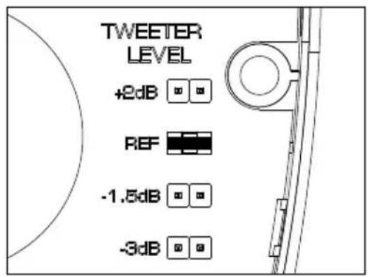
aDJusTaBle TweeTer leVel
C5 crossover networks also provide four levels of tweeter adjustability designed to compensate for different mounting locations, vehicle interiors and personal taste. These levels are selectable via a set of pins located under the clear cover of each crossover case. We recommend that you begin listening in the “REF” (Reference) position. To find the optimum tonal balance in your installation, experiment with alternate tweeter level settings by moving the pins. It is safe to switch jumpers while the system is playing.

sPeaKer PlaCemenT ConsIDeraTlons
A component system gives you the ability to place the woofer and tweeter separately in your vehicle interior. This can be good or bad, depending on how it's done. As a general rule, the tweeters should be placed relatively close to the woofers for best tonal balance and most coherent imaging (the closer, the better). Any separation greater than 8 inches (20 cm) is likely to result in degraded sound quality.
Avoid placing tweeters where they will be blocked by objects in the interior of the car (including seated occupants). When selecting a mounting location, look at both sides of the car to make sure that this location is clear on both sides.
You can always experiment with tweeter placement before committing to a final mounting location. Simply connect the rest of the system and allow plenty of wire length for the tweeters. Using Velcro ^® or similar material, attach the tweeters in different locations until you find the one where they perform best.
Woofers will usually be placed into factory speaker locations. If you have some woofer mounting flexibility, keep the following in mind: Lower mounting locations, such as the lower front corner of a door or a kick-panel provide the greatest path length distances for the sound emitted by the woofer. For this reason, they are generally more desirable than higher mounting locations. Higher mounting locations often result in extreme near-side soundstage bias which compromises the stereo listening experience.
DiaGram a: less DesIraBle sPeaKer PlaCemenT

natural_image
Line drawing of a car door with handle and side panel (no text or symbols)
natural_image
Line drawing of a car door with handle and side panel (no text or symbols)DlaGram B: more DeslraBle sPeaKer PlaCemenT

natural_image
Line drawing of a car door with handle and side panel (no text or symbols)!! WARNING
Double check the clearance for both speakers before proceeding. Many cars are different from one side to the other!
WOOFER INSTALLATION
The woofers should be installed in one of the following ways depending on location:
Factory Location: If you will be using the factory speaker wires, it may be necessary to change the terminations. This may be accomplished by using an adaptor plug or simply by cutting the factory connector off and using the supplied crimp connectors to terminate the speaker wires. The large connector is for the positive (+) terminal and the small connector is for the negative (−) terminal of each woofer. Keep in mind that the woofer wires must be connected to the woofer outputs of the crossovers supplied with your system as shown in the diagram on page 5. If you prefer to run new wires, refer to the “Custom Location” installation section for details. Whichever method you choose, observe correct polarity in your connections. If you are unsure about any of these issues, contact your JL Audio dealer for installation assistance.
Your new speakers have been designed to install, without modifications, into most vehicles that accept a 5x7-inch (125 x 180 mm) speaker. Most factory 5x7-inch speakers use four mounting screws which will line up with the mounting holes on your woofers.
A spacer gasket has been included to fine-tune speaker fitment. This gasket can be mounted on the front of the mounting flange, the back of the mounting flange or simply not be used in the installation. It is absolutely vital that the speaker frame fits into the mounting hole cleanly. This must be checked prior to tightening the screws. Do not force the frame into a hole that is too small. Do not tighten the speaker onto an uneven surface. This will damage your speakers. The speaker should also fit so that air does not leak around the mounting flange. Air leaks will cause a severe degradation in sound quality. Seal any air leaks with an automotive-grade sealant material.
Use the supplied mounting clips unless the factory holes already feature threaded inserts.
Hand-tighten the screws evenly.
Custom Location: Run speaker wire to the desired mounting locations. If you are running wires into a door, use existing factory wiring boots whenever possible. If you are drilling new holes, file their edges and install rubber grommets into each hole. Wires should then be covered with a protective, flexible PVC sleeve and then run through the door jamb. Make sure that the wires will clear door hinges and other structures in the door. If you are unsure about any part of this process, please contact your JL Audio dealer for installation help.
Double check the clearance for both speakers before proceeding.
Select an even surface. Tightening a speaker onto an uneven surface can damage it. Use the supplied template to mark the desired mounting location. Mark the center and the outline of the mounting hole as well as the mounting screw positions. Before drilling or cutting on your interior panels, use a utility knife to cut any fabric, vinyl or leather from hole locations. These materials can easily be snagged by a drill or a saw, causing damage to the panel and possible bodily injury. Drill four 1/8-inch (3 mm) holes for the speaker's mounting screws at the positions you have marked. Also drill a pilot hole in the center of the speaker mounting hole at this time. Then, using a saber saw, make the circular cut out for the speaker. File any rough edges. Insert the mounting clips with the flat side towards the speaker as shown in the Diagram C.
It is absolutely vital that the speaker frame fits into the mounting hole cleanly. This must be checked prior to tightening the screws. Do not tighten the speaker onto an uneven surface! This will damage your speakers. The speaker should also fit so that no air leaks around the mounting flange. Air leaks will cause a severe degradation in sound quality. Seal any air leaks with silicone, rope caulk or similar sealant material.
A spacer gasket has been included to fine-tune speaker fitment. This gasket can be mounted on the front of the mounting flange, the back of the mounting flange or simply not be used in the installation.
Connect the speaker wires, observing correct polarity, and secure the speaker and grille tray to the panel by evenly tightening by hand the provided #8 x 1.25 inch (16 mm) mounting screws. Make sure the woofer is secured so that air does not leak around the mounting flange. Air leaks will cause a severe degradation in sound quality. Seal any air leaks with an automotive-grade sealant material.
DiaGram C: FaCTory/CusTom IoCaTlon wooFer InsTallaTlon oPTlons

!! WARNING
Hand-tighten the screws evenly in a criss-cross pattern to avoid bending the speaker frame or stripping the mounting clips.
TWEETER INSTALLATION
First, run speaker wires from the tweeter output of the crossover (see diagrams on page 5) to the desired tweeter mounting locations, observing the same precautions as mentioned in the woofer installation section. Terminate the wires with the supplied 2.8 mm male crimpable connectors.
TWEETER FIXTURE INSTALLATION
The dome tweeters supplied with your C5-570 system have been designed for maximum mounting versatility. There are two primary methods by which the tweeters can be mounted in your vehicle:
Flush-Mount: For tweeter integration in a clean, unobtrusive manner, you will use the supplied flush-mount cups. This compact mounting fixture is installed using the method illustrated in Diagram E and requires a mounting hole with a diameter of 1.50 in. (38.1 mm).
At least 3/4-inch (19 mm) of clearance is required behind the mounting surface of the tweeter for the spring clips and 1.18-inch machine screws used in mounting the fixture. It may be necessary in some limited depth applications to cut down the length of the machine screw, or to use a shorter screw (not supplied). Hand-tighten the machine screw until the fixture is secure.
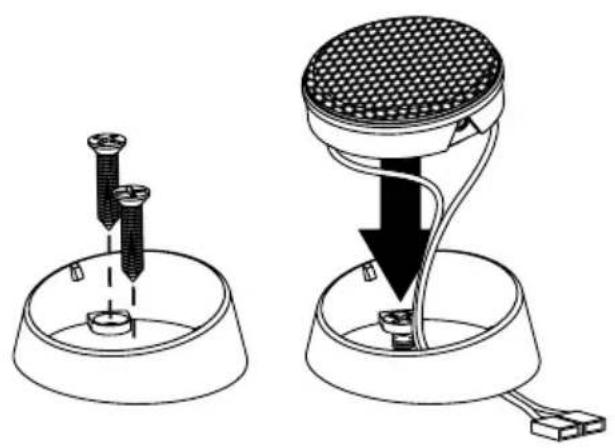
Surface-Mount: In this application, you will not need to cut large holes in your vehicle's panels for the tweeters. You will only need to drill a hole for the wires and two smaller holes for the mounting screws. This application is useful when mounting the tweeters to a panel that has insufficient clearance behind it for the tweeter's magnet structure.
Using the fixture as a template, mark the screw hole locations and a location in the center of the fixture for the wire hole. Remove the fixture and drill pilot holes for the screws and a 1/8-inch (3 mm) for the wires. Use the supplied #6 x 1-inch sheet metal screws to secure the fixture as shown in Diagram F (hand-tighten). Run the tweeter's wires through the hole and insert the tweeter until it snaps into place.
DiaGram e: FlusH-mounT TweeTer InsTallaTlon
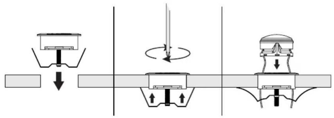
DiaGram F: surFaCe-mounT TweeTer InsTallaTlon
natural_image
Diagram showing two mechanical components: a screw holder and a sensor device with a mesh top, both without any text or symbols.JL AUDIO warrants these speakers (and crossover networks, where applicable) to be free of defects in materials and workmanship for a period of one (1) year.
This warranty is not transferable and applies only to the original purchaser from an authorized JL AUDIO dealer. Should service be necessary under this warranty for any reason due to manufacturing defect or malfunction, JL AUDIO will (at its discretion), repair or replace the defective product with new or remanufactured product at no charge. Damage caused by the following is not covered under warranty: accident, misuse, abuse, product modification or neglect, failure to follow installation instructions, unauthorized repair attempts, misrepresentations by the seller. This warranty does not cover incidental or consequential damages and does not cover the cost of removing or reinstalling the unit(s). Cosmetic damage due to accident or normal wear and tear is not covered under warranty.
Any applicable implied warranties are limited in duration to the period of the express warranty as provided herein beginning with the date of the original purchase at retail, and no warranties, whether express or implied, shall apply to this product thereafter. Some states do not allow limitations on implied warranties, therefore these exclusions may not apply to you. This warranty gives you specific legal rights, and you may also have other rights which vary from state to state.
If you need service on your JL AUDIO product:
All warranty returns should be sent to JL AUDIO freight prepaid through an authorized JL AUDIO dealer and must be accompanied by proof of purchase (a copy of the original sales receipt.) Direct returns from consumers or non-authorized dealers will be refused unless specifically authorized by JL AUDIO with a valid return authorization number. Warranty expiration on products returned without proof of purchase will be determined from the manufacturing date code. Coverage may be invalidated as this date is previous to purchase date. Return only defective components. If one speaker fails in a system, return only that speaker component, not the entire system. Non-defective items received will be returned freight-collect. Customer is responsible for shipping charges and insurance in sending the product to JL AUDIO. Freight damage on returns is not covered under warranty.
For Service Information in the U.S.A. please call
JL Audio Customer Service: (954) 443-1100
9:00 AM – 5:30 PM (Eastern Time Zone)
JL Audio, Inc
10369 North Commerce Pkwy.
Miramar, FL 33025
International Warranties:
Products purchased outside the United States of America are covered only by that country's distributor and not by JL Audio, Inc.

- C5-570 sPeCIFICaTlons
- Included Components and Parts:
- GeTTInG sTarTeD
- CrossoVer neTworK InsTallaTlon
- !! WARNING
- TweeTer ProTeCTlon
- CrossoVer neTworK aDJusTmenT
- aDJusTaBle mIDranGe PresenCe
- aDJusTaBle TweeTer leVel
- sPeaKer PlaCemenT ConsIDeraTlons
- WOOFER INSTALLATION
- Double check the clearance for both speakers before proceeding.
- DiaGram C: FaCTory/CusTom IoCaTlon wooFer InsTallaTlon oPTlons
- TWEETER INSTALLATION
- TWEETER FIXTURE INSTALLATION
- If you need service on your JL AUDIO product:
Brand : JL Audio
Model : Evolution C5-570
Category : Loudspeaker