Stealthbox SB-Y-YXZ1SPKR/M3-650i - Speaker JL Audio - Free user manual and instructions
Find the device manual for free Stealthbox SB-Y-YXZ1SPKR/M3-650i JL Audio in PDF.

User questions about Stealthbox SB-Y-YXZ1SPKR/M3-650i JL Audio
0 question about this device. Answer the ones you know or ask your own.
Ask a new question about this device
Download the instructions for your Speaker in PDF format for free! Find your manual Stealthbox SB-Y-YXZ1SPKR/M3-650i - JL Audio and take your electronic device back in hand. On this page are published all the documents necessary for the use of your device. Stealthbox SB-Y-YXZ1SPKR/M3-650i by JL Audio.
USER MANUAL Stealthbox SB-Y-YXZ1SPKR/M3-650i JL Audio
natural_image
Two black-and-white electric vehicle headsets with blue LED fans and connecting cables, shown against a white background (no text or symbols visible)Stealthbox®
INSTALLATION GUIDE for the
SB-Y-YXZ1SPKR/M3-650i
SKU# 94678
2016 & Up Yamaha YXZ1000R
Enclosure Type: Sealed
Driver Type: M3-650X-S-Gm-i
Nominal Impedance: 4 ohms
Continuous Power Handling: 60 watts (RMS method)
SB-Y-YXZ1SPKR/M3-650i INSTR_SKU#011544
! IMPORTANT
If you choose to perform the installation yourself, it is absolutely vital that the Stealthbox® be properly mounted to the vehicle according to these instructions. Failure to mount the enclosure properly presents two problems:
1) The sub-bass performance will suffer due to the movement of the enclosure caused by the force exerted by the woofer(s).
2) A loose enclosure presents a serious safety hazard in the event of a collision or sudden deceleration.
INSTALLATION DIFFICULTY:

ESTIMATED TIME: 1 HOUR

text_image
JL AUDIO - Quality & Design - SBX STEALTHBOX®Thank you for choosing a JL Audio Stealthbox* for your automotive sound system. With proper installation, your new vehicle-specific enclosed subwoofer system will deliver years of listening pleasure.
We strongly recommend that you have your new Stealthbox* installed by your authorized JL Audio dealer. The installation professionals employed by your dealer have the necessary tools and experience to disassemble and reassemble your vehicle properly. If you prefer to perform your own installation, please read this installation guide completely before beginning the process.
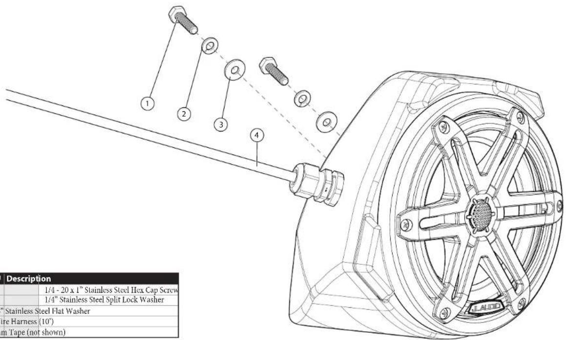
INCLUDED HARDWARE
(hardware pictured for one)
text_image
1/4 - 20 x 1" Stainless Steel Hex Cap Screw 1/4" Stainless Steel Split Lock Washer "Stainless Steel Flat Washer Wire Harness (10') um Tape (not shown) Description 1/4 - 20 x 1" Stainless Steel Hex Cap Screw 1/4" Stainless Steel Split Lock Washer| BOM ID Qty SKU | Description |
| 1 4 153820 | |
| 2 4 153819 | |
| 3 4 153738 1/4" | Stainless Steel Flat Washer |
| 4* 2 152414 Wire Harness (10') | |
| - 1 150249 Foam Tape (not shown) | |
* Pre-installed on enclosure
Note: For optimum performance, JL Audio recommends applying the included Foam Strips (or sound damping material) to surrounding plastic panels to reduce unwanted vibrations.
WIRING INFORMATION
Wiring Harness Info
| Wire Size Wire Color Use | ||
| 16 AWG | Red/Stripe | Speaker Positive (+) |
| Black/Stripe | Speaker Negative (-) | |
| 20 AWG | Red | Red RGB LED Negative (-) |
| Green | Green RGB LED Negative (-) | |
| Blue | Blue RGB LED Negative (-) | |
| Yellow | Main RGB LED Positive (+) | |
Adjustable control of RGB lighting may be achieved with the use of an RGB lighting controller (sold separately). Note: When selecting an RGB lighting controller, make sure that the total amperage demands of all LED circuits does not exceed the output capacity of the controller. For each M3-650X speaker, a 150 mA fuse is recommended. For optimal performance, we recommend using the JL Audio marine lighting controller (MLC-RW).
Direct LED Wiring
Alternatively, you may hard wire individual leads or a combination of leads to achieve up to seven different LED color assortments. Refer to the table below for the wire colors used to achieve specific LED colors.
| LED Color Wire Color(s) Connection | ||
| Red Red | Combine selected wires from all speakers and connect to negative ground or the negative (-) battery post. | |
| Green Green | ||
| Blue Blue | ||
| Yellow Red and Green | ||
| Pink Red and Blue | ||
| Aqua Green and Blue | ||
| White Red, Green and Blue | ||
| Combine all YH.I.LOW (+12V) leads together (parallel) and connect to a switched +12V supply. | ||
LED Wiring Considerations
- For short-circuit protection, we recommend installing a fuse (not included) at EACH speaker's YELLOW (+12V) LED power connection lead.
- We recommend activating the speakers' LEDs thru an interior lighting circuit that supplies +12V via an existing switch. If an existing switched circuit is not available, you may install a dedicated toggle/rocker style switch that will supply positive (+12V) power. Fuse this main +12V connection according to the total demands of all LED circuits.
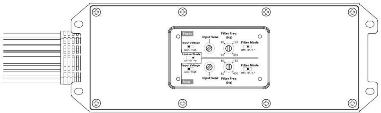
POWER RECOMMENDATION
JL Audio recommends high quality amplifiers such as the JL Audio MX280/4. The diagram below shows the recommended crossover settings for the MX280/4. For a detailed description of the amplifier settings, consult the owner's manual for the amplifier. If another amplifier is being used, please reference this illustration and use similar settings on that amplifier.
text_image
Front Input Voltage Low / High Channel Mode Input Voltage Low / High Rear Input Sens Filter Freq (Hz) 80 150 Filter Mode 30 400 Off/HP/LP 80 150 Filter Mode 30 400 Off/HP/LP Filter Freq (Hz)CONNECTIONS
Using quality power, signal, and speaker wire is essential in ensuring the performance of your Stealthbox ^6 . JL Audio recommends using a 4 AWG power kit such as the XD-PCS4-1B for your Stealthbox ^9 amplifier. Other kits are available should you be using more than one amplifier. Signal wire such as the JL Audio Premium Audio Interconnect Cables should be used to provide signal for both channels of the amplifier. JL Audio recommends using 12 AWG speaker wire for subwoofers such as our XC-BCS12-25.

natural_image
Close-up of a car's interior panel with visible wiring and a perforated vent (no text or symbols)STEP 1
The following steps show the installation procedure for the driver's side only, but the procedure is the same for both sides. Note: MX speakers (instead of M3) were used for photography purposes only.
Empty the driver's side of the vehicle.
natural_image
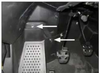
Close-up of a mechanical component with two white arrows pointing to features, no visible text or symbolsSTEP 2
Remove the two indicated factory bolts.
natural_image
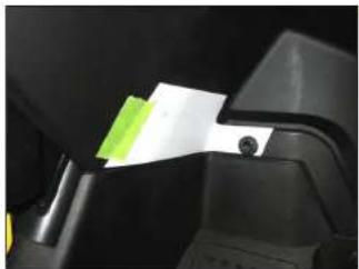
Close-up of a black mechanical component with a green sticky note attached, showing no visible text or symbols.STEP 3
Cut the Template from Page 8 of this manual.
Align the hole in the Template to the factory hole in the vehicle, and secure using the factory bolt removed in the previous step. Align the bottom of the Template with the horizontal edge of the plastic panel, and secure with tape, as shown.
natural_image
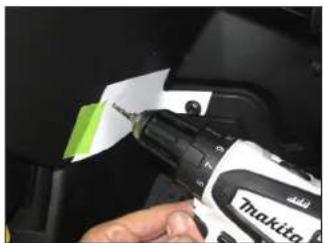
Close-up of a hand using a Driller-Makita tool to apply material, no visible text or symbols on the tool itself.STEP 4
Using a 1/8" drill bit, carefully drill through the indicated mark on the Template, through the plastic panel, to the exterior wheel well area.
Remove the factory bolt, and remove the Template.
Page 5 • J. Audio, Inc., 2019 Continued on Next Page
SB-Y-YXZ1SPKR/M3-650i INSTR_SKU#011544
natural_image
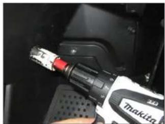
Close-up of a robotic welding torch with red trigger, held in hand (no visible text or symbols)STEP 5
Using a 1-1/8" hole saw, enlarge the hole drilled in the previous step.

natural_image
Close-up of a black automotive component being adjusted with a tool, showing a small metallic object inserted into the surface (no text or symbols visible)STEP 6
From outside the vehicle in the wheel well area, remove the two factory speed clips. These will not be reused.

natural_image
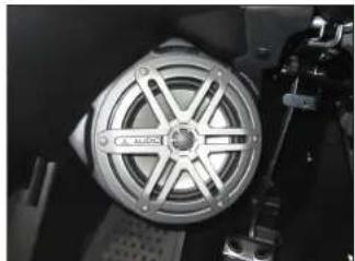
Close-up of a mechanical component with a metallic circular component and mounting feet (no visible text or symbols)STEP 7
Pass the speaker cable exiting the speaker enclosure through the hole drilled in Step 5.
natural_image
Close-up of a metallic mechanical component with radial slots and mounting brackets (no visible text or symbols)STEP 8
Position the speaker enclosure flush against the kick panel, allowing the grommet to sit in the drilled hole. Align the threaded inserts in the back of the enclosure with the two factory holes.

natural_image
Close-up of a hand using a handheld tool to adjust or install a car interior component (no visible text or symbols)STEP 9
Slide a 1/4" Split Lock Washer and a 1/4" Flat Washer over each 1/4 - 20 x 1" Hex Cap Screw.
From the exterior wheel well area, pass an assembly through each of the factory holes, into the threaded inserts in the back of the speaker enclosure, and fully tighten.

natural_image
Close-up of a metallic mechanical component with radial slots and mounting bracket (no visible text or symbols)STEP 10
Route the cable as necessary. Refer to Page 3 for wiring information.
Repeat the process for the passenger side.
Note: For optimum performance, we recommend applying the included Foam Strips (or sound damping material) to surrounding plastic panels to reduce unwanted vibrations.
SB-Y-YXZ1SPKR/M3-650i INSTR_SKU# 011544
CONGRATULATIONS!
You have completed the installation for this model! Enjoy your new Stealthbox®!

natural_image
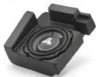
Interior view of a yellow and white sports car cockpit with steering wheel, dashboard, and control panel (no visible text or symbols)RECOMMENDED SUBWOOFER SOLUTIONS
A Stealthbox ^® subwoofer system is also available for your vehicle. Each weatherproof enclosure houses a premium JL Audio subwoofer and is designed for a perfect fit.
SB-Y-YXZ1/10TW3 SKU# 94642
JLAUDIO. How we play.
(954) 443-1100
www.jlaudio.com
All non locations are subject to change in their values. A, Audio® and the A, Audio logo: "Standard" and the Standard logo, and they are play "the registered trademarks of J. Audio, Inc. (World of the Cap) and International logo on material of J. Audio, Inc.
Format in USA - 927013, Audio Inc. = Formulated Direct Information about https://www.bosera.com/
JLA-SKU# 011544 • ver. 10.29.2019 • 10369 NORT- COMMERCE PARKWAY • MIRAMAR, FLORIDA • 33025 • USA

"011544"
This page is intentionally left blank.
SB-Y-YXZ1SPKR/M3-650i INSTR_SKU# 011544
TEMPLATES
SB-Y-YXZ1SPKR/M3-650i INSTR_SKU# 011544
Carefully cut out the templates along the indicated lines.
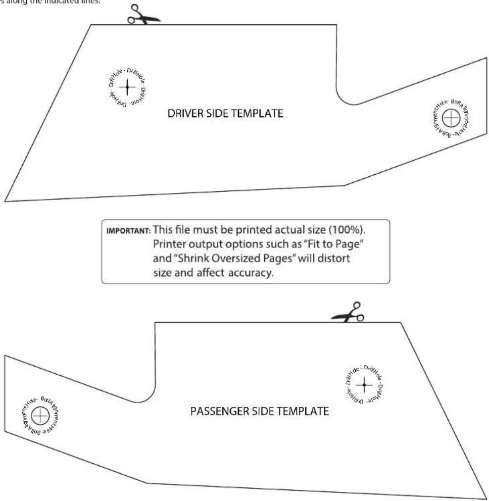
text_image
DRIVER SIDE TEMPLATE IMPORTANT: This file must be printed actual size (100%). Printer output options such as "Fit to Page" and "Shrink Oversized Pages" will distort size and affect accuracy. PASSENGER SIDE TEMPLATEPage 8 • J. Audio, Inc., 2019