SLSPSKT205 - Solar panel SereneLife - Free user manual and instructions
Find the device manual for free SLSPSKT205 SereneLife in PDF.

User questions about SLSPSKT205 SereneLife
0 question about this device. Answer the ones you know or ask your own.
Ask a new question about this device
Download the instructions for your Solar panel in PDF format for free! Find your manual SLSPSKT205 - SereneLife and take your electronic device back in hand. On this page are published all the documents necessary for the use of your device. SLSPSKT205 by SereneLife.
USER MANUAL SLSPSKT205 SereneLife
natural_image
Close-up of a solar panel with attached cable and connector, no visible text or symbols*☆☆☆☆☆☆☆
☆☆☆☆☆☆☆☆☆☆☆☆☆☆☆☆☆☆☆☆☆☆☆☆☆☆☆☆☆☆☆☆☆☆☆☆☆☆☆☆☆☆☆☆☆☆☆☆☆☆☆☆☆☆☆☆☆☆☆☆☆☆☆☆☆☆☆☆☆☆☆☆☆☆☆☆☆☆☆☆☆☆☆☆☆☆☆☆☆☆☆☆☆☆☆☆☆☆☆☆
100W x 2 Off-Grid Solar Panel Kit
with 30A PWM Controller with LCD Screen
USER GUIDE
Carefully read through these installation instructions before installing, operating or servicing PV system. Failure to follow these instructions may result in bodily injury or damage to property. Keep these instructions! Working on a PV system (installation, setup, maintenance, repairs) must be carried out by qualified and authorized persons.
Electrical Characteristics
The tolerance of Electrical Characteristics is ±3% under standard conditions (irradiance of 1000mW/cm ^2 , AM 1.5 spectrum, and cell temperature of 25°C or 77°F.
WARNING:
Danger of death from electric shock!
- Solar modules generate electricity as soon as they are exposed to light.
One module on its own is below the safety extra low volt level, but multiple modules connected in series (summing the voltage) or in parallel (summing the current) represent a danger. The following points must be observed when handling the solar modules to avoid the risk of fire, sparking and fatal electric shock. - Do not insert electrically conducting parts into the plugs or sockets!
Fit solar modules and wiring with wet plugs and sockets! - Exercise utmost caution when carrying out work on wiring and safety equipment (use insulated tools, insulated gloves, ect.)!
- Do not use damaged modules! Do not dismantle modules!
Do not mark on the rear of the module using sharp objects! - Exercise utmost caution when working on wiring and the inverter.
Be sure carefully to follow manufacture's installation instructions!
Artificially concentrated sunlight shall not be directed on the module or panel.
Danger of death from arcing!
Modules generate direct current when light shines on them. An arc may be produced when connections are separated. We therefore recommended covering modules with a lightproof cloth during installation.
When breaking a connected string of modules (e.g. when disconnecting the DC line from the inverter under load), a lethally strong arc can occur:
- Never disconnect the solar generator from the inverter while the inverter is connected to the mains grid—remove the fuse from the AC side on the inverter first!
- Ensure cable connections in perfect condition (no splitting, soiling or other contamination)
GENERAL SAFETY INFORMATION
Ensure that the module is used only in applications for which it is suitable (see Installing the modules). All work on a PV system (installation, setup, maintenance, repairs) must be carried out only by appropriately qualified and authorized persons. The appropriate DIN standards, construction rules and safety instructions are to be followed for installation.
UNPACKING THE MODULES AND STORAGE
The utmost care is required when handling the modules.
Be careful when unpacking, transporting, and storing the modules:
- Transport modules in an upright position.
- Carry modules with both hands. Do not use the connection socket as a handle.
- Ensure modules do not bow under their own weight.
- Do not place modules on top of each other.
- Do not subject to load, do not stand on them.
- Do not mark using sharp implements.
- Do not stand on the panel.
- Keep all electrical contacts clean and dry.
If it is necessary to store the modules temporarily, a dry, ventilated room should be used.
INSTALLING THE MODULES
When installing the modules, please pay attention to: the assembly is to be mounted over a fire resistant roof covering rated for the application.
- Keeping within the maximum permitted load.
The maximum mechanical load on the module must not exceed 5400pa.
To avoid exceeding the maximum mechanical load, site-specific live loads such as wind and snow should be taken into account.
• Environmental Conditions.
The module is intended for use in temperate climatic conditions. The module is "non-explosion-protected equipment". Hence it must not be installed in the proximity of highly inflammable gases and vapors (e.g. filling stations, gas containers, paint equipment). The module must not be installed near to naked flames or flammable materials. Do not expose modules to concentrated light sources. It must not be immersed in water or constantly exposed to water (e.g. from fountains). If there is exposure to salt (it is recommended that modules are installed at least 500m from the sea) and sulfur (sulfur sources, volcanoes), there is a risk of corrosion.
• Maximum number of modules in parallel and in series
When designing the system, we recommend that the maximum number of modules in parallel should be no more than four while the maximum number of modules in series no more than twelve.
Recommended maximum series/parallel module configurations: [Vsys/(1.25Voc)]/2
Please note:
- Our panel leading cable is 2.5mm2, and the maximum current it bears is 16A.
- Please choose suitable accessories according to the system demand and components' capacity guided by qualified electrician.
- Requirements of Installation
Make sure the modules' electrical performances in a system are the same. When connected in series, modules must all have the same amperage.
When connected in parallel, the modules must all have the same voltage.
Connect the quantity of modules that match the voltage specifications of the devices used in the system. The modules must not be connected together to create a voltage higher than the permitted system voltage. To minimize risk in the event of an indirect lightning strike avoid forming loops when designing the system. Artificially concentrated sunlight shall not be directed on the module or panel.
Modules must not be fitted as overhead glazing. Ensure that the mounting system can also withstand the anticipated wind and snow loads.
Precipitation can run off through small openings on the back side of the module. Make sure that these openings are not masked after mounting.
- Optimum Orientation and Tilt
To achieve the maximum annual yield figure out what the optimum orientation and tilt of the PV modules is. If sunlight shines vertical onto the PV modules you have the best conditions to generate maximum power.
- Avoid Overshadowing
Even the slightest partial shading (e.g. from dirt deposits) will cause a reduction in yield. A module is considered “shadow-free” if it is unobscured across its entire surface for the whole year and even on the shortest day of the year unobstructed sunlight can reach the module.
- Reliable Ventilation
Functioning ventilation prevents the build-up of heat, which would reduce performance.
- Earthing
Although the modules are certified to safety class II, we still recommend earthing them. The earth connection must be made by a qualified electrician.
Connect module frames to each other using cables with cable lugs. Use the hole (Φ7*11mm) attached that are provided for this purpose. To create the conductive connection (frame is anodized), use a serrated washer or a self-tapping screw (Φ5.5mm). The earth connection should be made by a qualified electrician.

text_image
Diagram of a mechanical assembly with numbered components, likely illustrating a machining or processing setup.- Stainless steel M6 nut
- Stainless steel serrated washer
- Stainless steel bolt
- Stainless steel connection head
- Grounding lead
All the junctions on the conductive connection must be fixed.
The fastness does not depend on soldering.
The metal containing iron in the conductive connection should be handled by some way, such as anodization, spray-painting, galvanization.
Stainless steel does not need to be handled.
MOUNTING
Installation of Frame and Module
The depth is no less than 3mm when installing the module into the frame.

text_image
Technical diagram showing three labeled components (1, 2, 3) of a mechanical or structural assembly with dashed lines indicating connection paths.- Module
- Silica
- Aluminum Frame
Connection between frames
The depth is no less than 3mm when installing the module into the frame.

text_image
Aluminum FrameInstallation Requirements
Each module must be securely fastened at a minimum of 4 points. The frame has been stress tested for mounting on the long sides. The module must not be secured by its short sides.

natural_image
Pure diagram of a rectangular frame with diagonal lines and three left-pointing arrows inside, no text or symbols present.
natural_image
Pure diagram of vertical arrows pointing up and down on a rectangular frame (no text or symbols)Example for mounting the PV modules to the substructure:
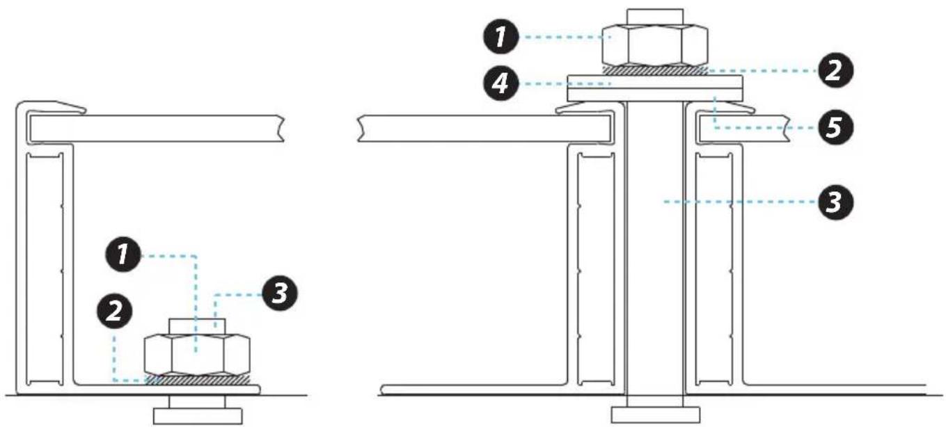
text_image
Technical diagram showing two mechanical assembly configurations with numbered components and dashed alignment linesExample A: Bolting Example B: Clamping on
- Stainless steel M6 nut
- Stainless steel spring washer
-
Stainless steel M6 t-head bolt
-
Aluminum clamping plate
-
EPDM washer 2mm
We recommend using a torque wrench for installation. In example B, the tightening torque (using stainless steel M6 bolts) should be around 15-20Nm. Use the existing holes for securing the module and do not drill additional holes (doing so would void the warranty). Use appropriate corrosion-proof fastening materials.
ELECTRICAL INSTALLATION
Cables and Wiring
Our modules are equipped with two (2) stranded, PV-rated, output MC4 cables. The positive connector is a male connector and the negative connector is a female connector. These wires by themselves are rated for series connections, but could be adapted to hold parallel connections with an extra component such as a combiner box or an MC4 adaptor for parallel strings. We recommends that only sunlight resistant cables be used with the minimum wire size being 2.5mm2 in diameter.
MC4 cables are intended for use on the output wiring of a module or panel and comply with the Standard for Connectors for use in Photovoltaic Systems, UL 6703, see module literature for appropriate mating connectors.
Keep connectors dry and clean and ensure that caps are tightly sealed before connecting modules. Faulty connections can result in electrical shock so make sure to fasten all connections securely.
Our modules can be installed in landscape or portrait orientation. Make sure that the proper distance between the panels and the surface to allow for air circulation.

natural_image
Two solar panel arrays shown side by side, one with grid pattern and the other with grid pattern (no text or symbols)Portrait Orientation Landscape Orientation
Series Connections are just plug and play with the male and female MC4 connectors.

natural_image
Pure electrical circuit lines without any symbolsParallel connections will utilize MC4 branch connectors for centralizing all positive and all negative connections.
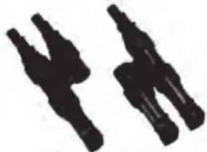
natural_image
Two black abstract shapes resembling stylized letters or symbols, no text or symbols presentCompatible manufacturers to Forward Electronics include Multi-Contact exclusively:
Female Type Multi-Contact (A: 4 - 6 mm ^2 , D: 5.5 - 9 mm)
Male Type Multi-Contact (A: 4 - 6 mm ^2 , D: 5.5 - 9 mm)
Marking or unique physical features for the connectors will include the physical company name, a do not disconnect symbol, a TUV certification symbol on the actual connector, and a polarity band whether it be red or black.
FOR THE WIRING, PAY ATTENTION TO:
- Correct wiring scheme
When designing the system, avoid forming loops (to minimize risk in the event of an indirect lighting strike). Check that wiring is correct before starting up the generator. If the measured open circuit voltage (Voc) and short-circuit current (Isc) differ from the specifications, then there is a wiring fault.
- Use of suitable materials
Use cable extensions and plugs that are designed for outdoor applications.
Ensure that they are in perfect electrical and mechanical condition. Use only cables having one conductor. Select the appropriate cable diameter to minimize voltage drop (to calculate the minimum cable diameter, the fuse, and to calculate controls, multiply the Isc and Uoc by a factor of 1.25). Under normal conditions, a photovoltaic module is likely to experience conditions that produce more current and/or voltage than reported at standard test conditions. Accordingly, the values of Isc and Voc marked on this module should be multiplied by a factor of 1.25 when determining component voltage ratings, conductor ampacities, fuse sizes, and size of controls connected to the PV output.
ROOF INSTALLING
- Use fasteners to fasten the modules to the mounting support structure.
Modules should be bolted to support structures through mounting holes located in the frame's back flanges only. Stainless-steel bolts, with nuts, washers, and locks washers, are recommended for module mounting. Creation of additional holes for mounting is not recommended and will invalidate the warranty.
Modules should not be mounted by supports at the ends.
- Mounting support structure should withstand forces from wind and snowfall pressure etc. Mounting support structure should use proper materials and corrosive treatment.
- Installation the modules on the roof should have proper ventilation. A clearance of 4.5 inches (about 115mm) or more behind the modules is recommended to permit air circulation and cooler module operation.
Elevated temperatures lower operating voltage and power, and shorten module lifetime. Clearance of 1/4 inch (6.35mm) or more between modules is required to allow for thermal expansion of the frames.
- The mounting support structure should be fire-proof.
- The modules' fire safety is class C.
MAINTENANCE AND CLEANING
Do not change the PV components optionally (diode, junction box, plug connectors). Given a sufficient tilt (at least 15^ ), it is not generally necessary to clean the modules (rainfall will have a self-cleaning effect). In case of heavy soiling (which will result in output reductions), we recommend cleaning the modules using plenty of water (from a hose) without cleaning agents and using a gentle cleaning implement (a sponge). Dirt must never be scraped or rubbed away when dry, as this will cause micro-scratched. We recommend the system is inspected at regular intervals.
Checklists:
- All fastenings are tight and secure and free of corrosion.
- All cable connections are secure, tight, clean and free of corrosion.
- Cables are not damaged in any way.
- Checking the earthing resistivity of metals.
What's in the Box:
• (2) 100W Mono Solar Panel
• 30A Solar charge controller (White)
• (2) Sets of Mounting hardware / Z-brackets
- 20' Solar Extension Cable (Red), Pre-assembled Female Connector (between solar panel to controller)
- 20' Solar Extension Cable (Black), Pre-assembled Male Connector (between solar panel to controller)
- 8' Extension Cable (Red), Pre-assembled Battery Lug (between controller to battery)
- 8' Extension Cable (Black), Pre-assembled Battery Lug (between controller to battery)
• 15A Fuse and Replacement
• (10) Wire Fixers
• A Pair of MC4 Connectors
This product can expose you to a chemical or group of chemicals, which may include "Di (2-ethylhexyl) phthalate (DEHP)" which is known in the state of California to cause cancer, birth defects, or other reproductive harm. For more info, go to https://www.p65warnings.ca.gov/.
Features:
- Includes 30A PWM Controller with LCD Screen
- Portable and Easy Set-Up
- Sleek Design for Aesthetic Quality
• Grade A Mono Solar Cells
• Higher Module Conversion Efficiency
• Each Panel Produces 300-600Wh a day - Generates 5.3 amp Power
• Charges 12/24 Volt Battery - Anodized Aluminum Frame to Protect Solar Cells & Convenient for Installation
- Pre-drilled Holes, Compatible with Common Ground Mounts
- Foam Box for Safe Transport and Easy Storage
- Dust Tight and Waterproof with IP67 Rating
- Set Up in Just 5 Minutes for Solar Starters
• Used for Marine, Dry Camp, RVs, and Other Off-grid Applications
Technical Specs:
• Power Supply: 100W x 2
- Fuse: 15A
- Short-Circuit Current (Isc): 5.85A
- Open-Circuit Voltage (Voc): 23.1V
• Maximum Power Voltage (Vmp): 18V
• Maximum System Voltage: 1000V
• Tolerance of PMax: ±3%
- Series Fuse Rating: 15A
• Maximum Power Current (Imp): 5.32A
- Battery Type: 12V Lead-acid and Lithium-ion Batteries (Battery Not Included in the System)
• Cell Type: High-Efficiency Monocrystalline
- Operating Temperature: Controller and Inverter: -20^ - 50^
• Solar Panel: -40°C-85°C
- Controller Voltage: 12V/24V
- Max. Input: < 50V
- USB Output: 5V/2A
- Standby Current: < 12mA
- Type of Connector: MC4 Connector
• Wire/Cable Length: 35.4 -inch
- Product Dimension: 36" x 26.2" x 1.4"-inches
serenelife™
Questions? Issues?
We are here to help!
Phone: (1) 718-535-1800
Email: support@pyleusa.com