
VTEC36 - Grill Vulcan - Free user manual and instructions
Find the device manual for free VTEC36 Vulcan in PDF.

| Product Type | Commercial Infrared Gas Grill |
| Brand | Vulcan |
| Model | VTEC36 |
| Number of Burners | 3 |
| Total Heat Output | 66,000 BTU/h |
| Gas Supply | Natural gas or propane (according to nameplate) |
| Minimum Supply Pressure | Natural gas: 18-23 cm WC; Propane: 28-30 cm WC |
| Pressure Regulator | Provided, set to 12.7 cm WC (NG) or 25.4 cm WC (LP) |
| Cooking Grid Material | Stainless steel |
| Emitter Panel Material | Stainless steel (consumables) |
| Main Functions | Infrared cooking, MAX/MIN adjustment, manual or spark ignition |
| Weekly Maintenance | Clean grids, emitter panels and crumb tray; vacuum debris |
| Daily Maintenance | Let run on MAX for 10 minutes after cooking to burn off residues |
| Recommended Preheating | 20 minutes on MAX |
| Stainless Steel Surface Cleaning | Damp cloth with mild soap, Scotch-Brite pad in the direction of the grain |
| Lubrication | Valves lubricated by qualified technician with high-temperature oil |
| Ventilation | Mandatory ventilation hood; minimum 0 cm clearance at rear and sides (non-combustible walls) |
| Leveling | Adjustable legs; check level before and after installation |
| Safety | Do not operate without emitter panels; check for gas leaks before use |
| Spare Parts | Emitter panels (consumables), cooking grids, crumb tray |
| Repairability | Contact Vulcan customer service for repairs or adjustments |
| Installation Standards | Compliant with ANSI Z223.1/NFPA 54 (USA) or CAN/CSA B149.1 (Canada) |
| Usage | Commercial use only |
Frequently Asked Questions - VTEC36 Vulcan
User questions about VTEC36 Vulcan
0 question about this device. Answer the ones you know or ask your own.
Ask a new question about this device
Download the instructions for your Grill in PDF format for free! Find your manual VTEC36 - Vulcan and take your electronic device back in hand. On this page are published all the documents necessary for the use of your device. VTEC36 by Vulcan.
USER MANUAL VTEC36 Vulcan
natural_image
Exterior view of a stainless steel VULCAN grill with control knobs and grating (no visible text or symbols beyond branding)VTEC36
MODELS
VTEC14
VTEC25
VTEC36
VTEC48
VTEC60
For additional information on Vulcan or to locate an authorized parts and service provider in your area, visit our website at www.vulcanequipment.com
IMPORTANT FOR YOUR SAFETY
THIS MANUAL HAS BEEN PREPARED FOR PERSONNEL QUALIFIED TO INSTALL GAS EQUIPMENT, WHO SHOULD PERFORM THE INITIAL FIELD START-UP AND ADJUSTMENTS OF THE EQUIPMENT COVERED BY THIS MANUAL.
POST IN A PROMINENT LOCATION THE INSTRUCTIONS TO BE FOLLOWED IN THE EVENT THE SMELL OF GAS IS DETECTED. THIS INFORMATION CAN BE OBTAINED FROM THE LOCAL GAS SUPPLIER.
IMPORTANT
IN THE EVENT A GAS ODOR IS DETECTED, SHUT DOWN UNITS AT MAIN SHUTOFF VALVE AND CONTACT THE LOCAL GAS COMPANY OR GAS SUPPLIER FOR SERVICE.
FOR YOUR SAFETY
DO NOT STORE OR USE GASOLINE OR OTHER FLAMMABLE VAPORS OR LIQUIDS IN THE VICINITY OF THIS OR ANY OTHER APPLIANCE.
WARNING
Improper installation,
adjustment, alteration, service or maintenance can cause property damage, injury, or death.
Read the installation, operating and maintenance instructions thoroughly before installing or servicing this equipment.
IN THE EVENT OF A POWER FAILURE, DO NOT ATTEMPT TO OPERATE THIS DEVICE.
INSTALLATION, OPERATION AND CARE OF GAS COUNTERTOP CHARBROILERS
GENERAL
Gas Infrared Charbroilers are designed for commercial use only and feature fast, efficient gas heat. Each burner is controlled by an adjustable gas valve. Emitter panels are located directly above each burner to maintain uniform temperature and provide infrared cooking. The emitter panels will need to be replaced, depending upon your menu and hours of operation. Emitter panels and stainless steel cooking grids are easily removed for cleaning when cool. A crumb tray is provided to collect fat run-off and debris; it opens to the front for inspection or drain-off.
| Model | Number of Burners | BTU/hr Input Rating |
| VTEC14 | 1 | 22,000 |
| VTEC25 | 2 | 44,000 |
| VTEC36 | 3 | 66,000 |
| VTEC48 | 4 | 88,000 |
| VTEC60 | 5 | 110,000 |
INSTALLATION
UNPACKING
This charbroiler was inspected before leaving the factory. The carrier assumes full responsibility for the safe delivery upon acceptance of the shipment. Check for possible shipping damage immediately after receipt.
If the charbroiler is found to be damaged, complete the following steps:
- Carrier must be notified within 5 business days of receipt.
- Carrier's local terminal must be notified immediately upon discovery (note time, date, and who was spoken to), and follow up and confirm with written or electronic communication.
- All original packing materials must be kept for inspection purposes.
- The charbroiler cannot have been moved, installed, or modified.
- Notify Vulcan Customer Service immediately at 800-814-2028.
Carefully unpack your charbroiler and make sure that no parts are discarded with packaging material. A pressure regulator designed to operate with the broiler has been supplied and must be installed before the charbroiler is placed into service (Refer to GAS PRESSURE REGULATOR INSTALLATION in this manual).
Before installing, verify that the type of gas (natural or propane) and the clearance dimensions agree with the specifications on the rating plate which is located on the upper front corner on the right side.
LOCATION
The installation location must be kept free and clear of combustibles. Do not obstruct the flow of combustion and ventilation air. DO NOT install the charbroiler adjacent to fryers unless following the provisions detailed by local codes and/or the applicable sections of ANSI-Z223.1/NFPA #54 (latest edition) and NFPA #96 (latest edition) in the United States of America or CAN/CSA 149.1 (latest edition) and CAN/CSA149.2 (latest edition) in Canada.
Sufficient air should be allowed to enter the room to compensate for the amount of air removed by any ventilating system and for combustion of the gas burners. Do not obstruct the air flow into and around the appliance. Do not obstruct the flow of flue gases through and above the broiler's cooking grids. Position the broiler in its final location. Check that there are sufficient clearances to service the broiler and to make the required gas supply connection(s). Provide 36" clearance at the front for cleaning, maintenance, service and proper operation.
This broiler is for use in non-combustible locations only. Installation in combustible locations is prohibited unless following the provisions detailed by local codes and/or the applicable sections of ANSI-Z223.1/NFPA #54 (latest edition) and NFPA #96 (latest edition) in the United States of America or CAN/CSA 149.1 (latest edition) and CAN/CSA149.2 (latest edition) in Canada and approved by the authority having jurisdiction.
Minimum clearances to non-combustible walls are 0" to the rear and 0" to the sides.
INSTALLATION CODES AND STANDARDS
The Charbroiler must be installed in accordance with:
In the United States of America:
-
State and local codes.
-
National Fuel Gas Code, ANSI-Z223.1/NFPA #54 (latest edition). This shall include but not be limited to: NFPA #54 Section 10.3.5.2 for Venting. Copies may be obtained from The American Gas Association Accredited Standards Committee Z223, @ 400 N. Capital St. NW, Washington, DC 20001 or the Secretary Standards Council, NFPA, 1 Batterymarch Park Quincy, MA 02169-7471
NOTE: In the Commonwealth of Massachusetts
All gas appliances vented through a ventilation hood or exhaust system equipped with a damper or with a power means of exhaust shall comply with 248 CMR.
- NFPA Standard # 96 Vapor Removal from Cooking Equipment, latest edition, available from the National Fire Protection Association, Batterymarch Park, Quincy, MA 02269.
In Canada:
- Local codes.
- CAN/CSA-B149.1 Natural Gas Installation (latest edition)
- CAN/CSA-B149.2 Propane Installation Code (latest edition), available from the Canadian Gas Association, 178 Rexdale Blvd., Etobicoke, Ontario, Canada M9W 1R3
KEY COMPONENTS
WARNING The charbroiler and its parts are hot. Use care when operating, cleaning or servicing the charbroiler.
Cooking Grids – The cooking grids should always be in place and properly seated on the emitter panels during operation. Wash grids thoroughly with soap and water solution and rinse before first use.
Crumb tray – The crumb tray is the removable pan that catches any debris that falls from the broiling area. The crumb trays should be pushed all the way in while the unit is operation.
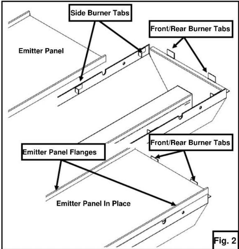
Emitter Panel – The charbroiler must never be operated without the emitter panels in place. The emitter panels protect the burner from food drippings and debris. Operating the burner without the emitter panels in place will cause poor performance and clogging of the burner ports. The emitter panels disperse energy and facilitate infrared cooking.
The emitter panels should rest on top of the side burner tabs and inside of the front and rear burner tabs over each burner. The emitter panels should be placed in position with the flanged edges pointing upwards. See Fig. 2.
Emitter panels are consumable. The emitter panels will need to be replaced, depending upon your menu and hours of operation.

LEVELING
It is important that the charbroiler is level front to back and left to right. Areas of uneven heat distribution will occur on an unleveled unit. The charbroiler is equipped with adjustable legs. Turn the feet at the bottom of the legs to adjust to level. The unit should be rechecked for level anytime it has been moved.
VENTILATION HOOD
The broiler should be installed under a suitable ventilation hood. For safe operation and proper ventilation, keep the space between the charbroiler and vent hood free from any obstructions.
GAS CONNECTION
The data plate on the lower right side of the charbroiler indicates the type of gas your unit is equipped to burn. DO NOT connect to any other gas type.
NOTICE All gas supply connections and any pipe joint compound must be resistant to the action of propane gases.
Purge the supply line to clean out any dust, dirt, or any foreign matter before connecting the line to the unit.
Codes require that a gas shut-off valve be installed in the gas line ahead of the charbroiler. The gas supply line must be at least the equivalent of 34 " iron pipe.
A pressure regulator is supplied and must be installed outside of the broiler when making the gas supply connection. Standard orifices are set for 4"WC (Water Column) for Natural Gas — 10"WC (Water Column) for Propane. Use the ^1/8 pipe tap on the burner manifold for checking pressure. Make sure the gas piping is clean and free of obstructions, dirt, and piping compound.
An adequate gas supply is necessary. Undersized or low pressure lines will restrict the volume of gas required for satisfactory performance. A minimum supply pressure of 7" W.C. for natural gas and 11" W.C. for propane gas is recommended. With all units operating simultaneously, the manifold pressure on all units should not show any appreciable drop.
When testing the gas supply piping system, if test pressures exceed 12 psig (3.45 kPa), the charbroiler and its individual shutoff valve must be disconnected from the gas supply piping system. When test pressures are 12 psig (3.45 kPa) or less, the charbroiler must be isolated from the gas supply piping system by closing its individual manual shut-off valve during any pressure testing of the system.
WARNING Prior to lighting, check all joints in the gas supply line for leaks. Use soap and water solution. Do not use an open flame.
GAS PRESSURE REGULATOR INSTALLATION
Gas regulator pressure is preset at 4" Water Column (W.C.) for natural gas, and 10" W.C. for propane gas. Minor adjustments may be required based on site specific gas pressure.
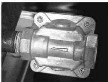
Install the regulator as close to the broiler on the gas supply line as possible. Make sure that the arrow on the underside of the regulator is oriented in the direction of gas flow to the broiler (Fig. 3) and the regulator is positioned with the vent plug and adjustment screw upright (Fig. 4).
natural_image
Close-up of a mechanical component with no visible text or symbolsFig. 3

natural_image
Close-up of a metallic industrial valve component with no visible text or symbolsFig. 4
The minimum supply pressure (upstream of the regulator) should be 7-9" W.C. for natural gas and 11-12" W.C. for propane gas. At no time should the charbroiler be connected to supply pressure greater than 12 psig (3.45 kPa) or 14" W.C.
CASTER EQUIPPED CHARBROILERS
Charbroilers mounted on stands with casters must use a flexible connector (not supplied) that complies with the Standard for Connectors for Movable Gas Appliances, ANSI Z21.69 • CSA 6.16 and a quick-disconnect device that complies with the Standard for Quick-Disconnect Devices for use With Gas Fuel, ANSI-Z21.41 • CSA 6.9. In addition, adequate means must be provided to limit movement of the broiler without depending on the connector and the quick-disconnect device or its associated piping to limit broiler movement. Attach the restraining device at the rear of the charbroiler. If disconnection of the restraint is necessary, turn off the gas supply before disconnection. Reconnect the restraint prior to turning the gas supply on and return the charbroiler to its installation position.
OPERATION
WARNING
The charbroiler and its parts are hot. Use care when operating, ing the charbroiler.
BURNER LIGHTING
The VTEC charbroiler does not have a pilot and each burner lights directly from a spark igniter or from an outside ignition source (such as a lit taper, long handle lighter, etc).
LIGHTING BURNER WITH SPARK IGNITER
- Turn the main gas shut-off valve and the individual burner control knobs to the OFF position (clockwise until stops). Wait 5 minutes.
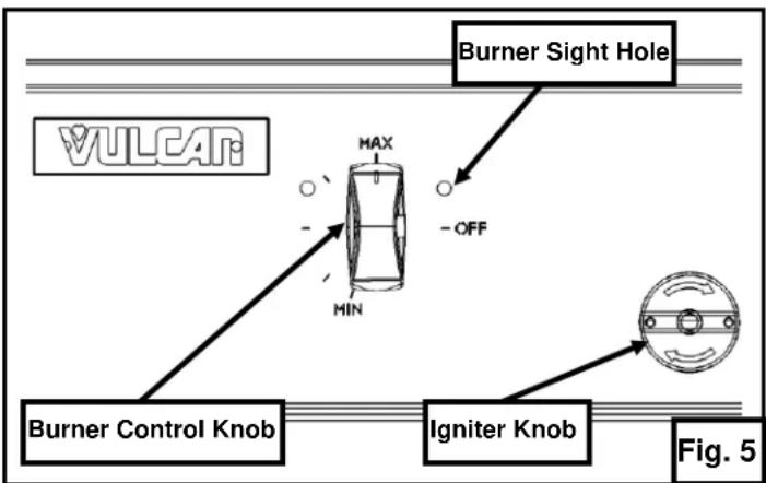
- Push and turn the burner control knob to the MAX setting (counterclockwise to vertical/90° position) on the burner you intend to light. (Fig. 5)
- Immediately, while viewing through the burner sight hole, turn the igniter knob clockwise until you hear a click (approx. 14 turn) and see the spark. The burner should ignite immediately and flames should be visible through the burner sight hole.
- If the burner fails to light immediately, repeat step 3, two more times. If the burner has still not ignited at this point, turn the main gas shut-off valve and all burner valves to the OFF position (clockwise until stops) and proceed with manual burner lighting instructions on following page.
- Repeat steps 2-4 until all burners are lit. Turn on one burner control knob at a time and ensure burner is lit before proceeding to light the next burner.
flowchart
graph TD
    A["Burner Control Knob"] --> B["Igniter Knob"]
    C["Burner Sight Hole"] --> D["Max/Min"]
    D --> E["-OFF"]
    F["Figure 5"] --> G["Oval"]
    style A fill:#f9f,stroke:#333
    style B fill:#ccf,stroke:#333
    style C fill:#cfc,stroke:#333
    style D fill:#fcc,stroke:#333
    style E fill:#cff,stroke:#333
    style F fill:#ffc,stroke:#333
    style G fill:#cfc,stroke:#333

OFF
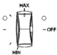
MAXIMUM
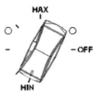
MINIMUM
Fig. 6
The burners should be left on the maximum (MAX) setting for most efficiency when cooking. The burners may be turned to the minimum (MIN) setting during slow periods to save energy. See Fig. 6.
LIGHTING BURNER MANUALLY
-
Turn the main gas shut-off valve and the individual burner control knobs to the OFF position (clockwise until stops). Wait 5 minutes.
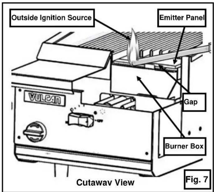
-
Apply a flame from an outside ignition source (such as a lit taper, long handle lighter, etc) directly to the gap between the bottom of the emitter panel and the top of the intended burner box at the front of the unit. See Fig. 7.
-
Push and turn the burner control knob to the MAX setting (counterclockwise to vertical/90° position) on the burner you intend to light. (Fig. 8)
-
View through the burner sight hole (Fig.8) to ensure the burner has lit.
-
If the burner fails to light within 4 seconds of applying flame to the directed area, turn the main gas shut-off valve and all burner valves to the OFF position (clockwise until stops). Contact an authorized service contractor.
-
Repeat steps 2-4 until all burners are lit. Turn on one burner control knob at a time and ensure burner is lit before proceeding to light the next burner.

TO COMPLETELY SHUTDOWN THE BURNERS
For complete shutdown: Turn the main gas supply valve OFF. Make sure all individual burner valves are OFF (turned completely clockwise until stops).
PREHEATING THE CHARBROILER
Allow the charbroiler to preheat for 20 minutes on the maximum (MAX) setting. Rub grates with cooking oil before using to help reduce sticking.
CLEANING
WARNING The charbroiler and its parts are hot. Use care when operating, cleaning or servicing the charbroiler.
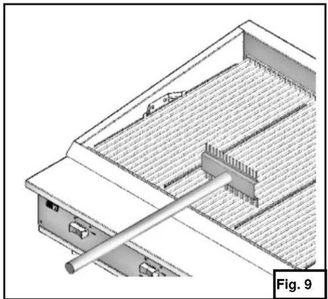
Scrape cooking grids during broiling with a stainless steel scraper or stainless steel wire brush to keep the grates clean. Do not allow debris to accumulate on the grates. (Fig. 9) Top grates may be immersed in cleaning compound overnight. In the morning, rinse with hot water to remove any residues of cleaning compound.
Stainless steel surfaces may be cleaned using damp cloth with mild detergent and water solution. Clean heavy, baked on grease and splatter that do not respond to normal cleaning by using cleaning solution with a Scotch-Brite™ pad. Rub with the grain of the surface – do not rub in a circular motion.
DAILY
After cooking, allow unit to run on MAX setting for 10 minutes before shutting OFF. This will make cleaning debris from the emitter panels easier when they cool down.
When cool, remove cooking grids and emitter panels, clean places where fat, grease, or food can accumulate. Brush or use scraper to remove any accumulated debris from emitter panel surfaces. Be careful to keep inside burner boxes clear of debris. Remove crumb tray when cool and empty. (Fig. 10)
natural_image
Technical diagram of a mechanical assembly with a rod inserted into a grid-patterned housing (no text or symbols)
NOTICE Never leave emitter panels wet after cleaning. Leaving panels wet after cooking or cleaning may accelerate corrosion process and result in premature failure.
WEEKLY
When cool, remove cooking grids, emitter panels and heat shield. Clean and vacuum any accumulated debris from inside burner boxes. Clean inside chassis area anywhere fat, grease, or food can accumulate. Clean heat shield while removed (Fig. 10). Repeat weekly process more often as needed.
NOTICE Never cover surface of unit with pans or other objects in attempt to "burn off" or clean debris from unit. This will cause a buildup of heat that can potentially damage and warp components of the charbroiler. Do not cover surfaces with aluminum foil as this may block or disrupt the designed air flow pattern and affect performance.
MAINTENANCE
WARNING The charbroiler and its parts are hot. Use care when operating, cleaning or servicing the charbroiler.
VENT SYSTEM
At least twice a year the exhaust hood (venting system) should be examined and cleaned.
LUBRICATION
All valves, at the first sign of sticking, should be lubricated by a trained technician using high temperature grease.
EMITTER PANELS
Emitter panels are consumable.
The emitter panels will need to be replaced, depending upon your menu and hours of operation. Replace emitter panels if warped or holes appear.
SERVICE
Contact your local Service Contractor for any repairs or adjustments needed on this equipment. For a complete listing of service and parts depots refer to www.vulcanequipment.com. When calling for service, the following information should be available from the appliance identification plate: Model Number and Serial Number.
TROUBLE SHOOTING
| Uneven heating | A. Burner valves improperly adjustedB. Fluctuating gas pressureC. Appliance is not levelD. Emitter panels are not properly seated or damagedE. Emitter panels are excessively dirty |
| Too much top heat | A. Faulty hood ventilationC. Overrated gas pressureD. Unit is excessively dirtyE. Emitter panels are not properly seated or damaged |
| Uneven heat side to side | A. Burner valves improperly adjustedB. Appliance is not level side to sideC. Crumb tray is not pushed all the way inD. Emitter panels are not properly seated or damagedE. Emitter panels are excessively dirty |
| Uneven heat front to back | A. Appliance is not level front to backB. Faulty hood ventilationC. Crumb tray is not pushed all the way inD. Emitter panels are not properly seated or damagedE. Emitter panels are excessively dirtyF. Designed air flow pattern obstructed |
| Burner not lighting | A. Check that igniter electrode is sparking when igniter knob is turned clockwiseB. Check for damaged, loose or dirty igniter wires, igniter and electrodeC. Burner valve not on MAX settingD. Gas pressure too lowE. Inside burner box or burner venturi excessively dirty |
| Burner flames too low | A. Burner valves improperly adjustedB. Gas pressure too lowC. Inside burner box or burner venturi excessively dirtyD. Clogged burner orifice |
| Burner flames to high | A. Emitter panels are not properly seated or damagedB. Gas pressure too high |
| Fluctuating gas pressure | A. Checked for clogged vent on regulator |
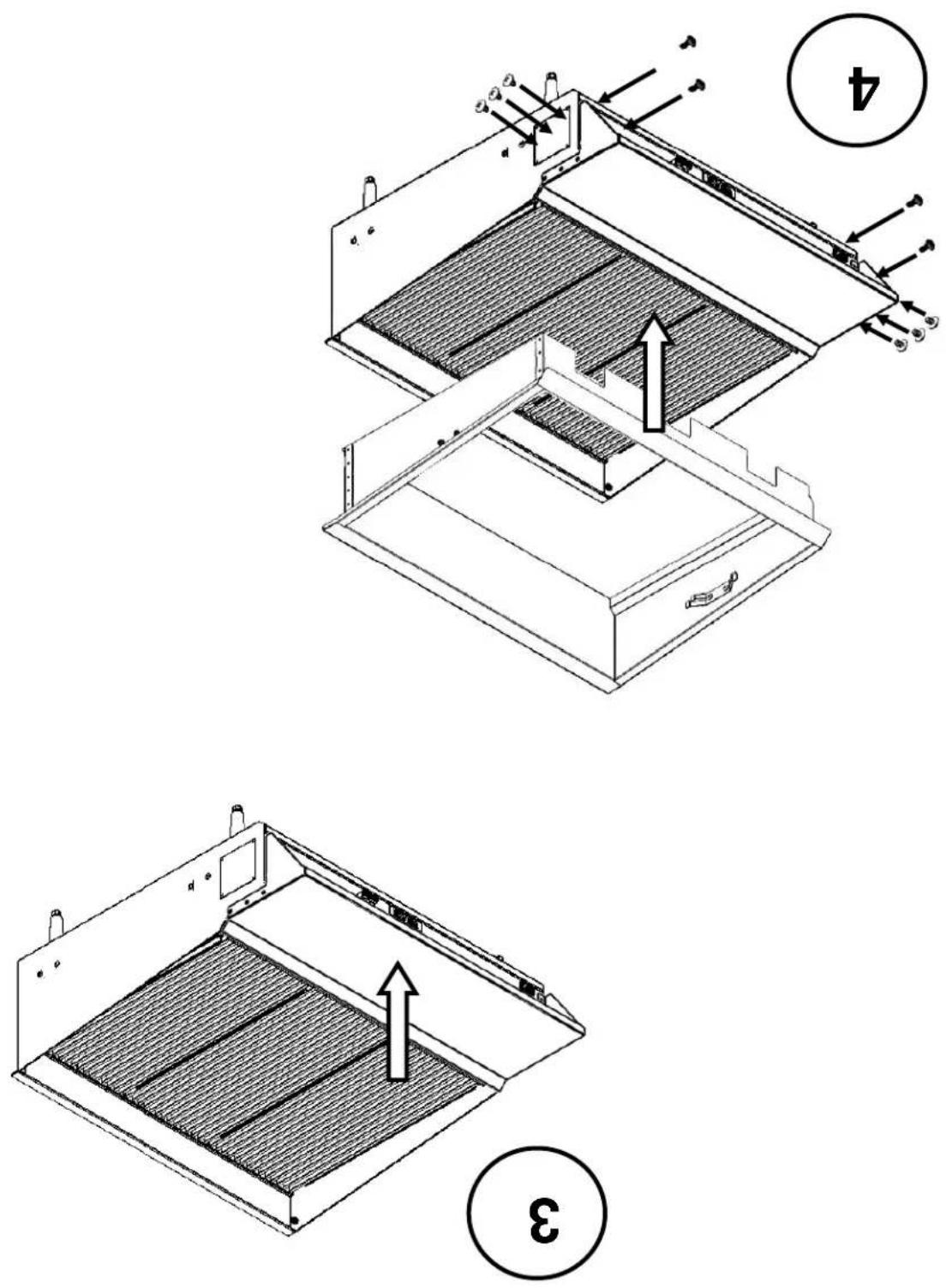
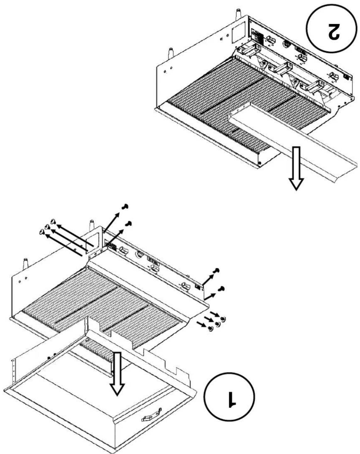
ACCESSORY INSTALLATION
WARNING
The charbroiler and its parts are hot. Use care when operating, cleaning or servicing the charbroiler.
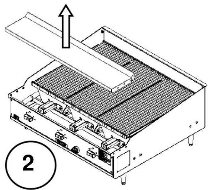
natural_image
Technical line drawing of a mechanical device with internal components and an upward arrow, labeled with number 2 (no text or symbols on the diagram itself)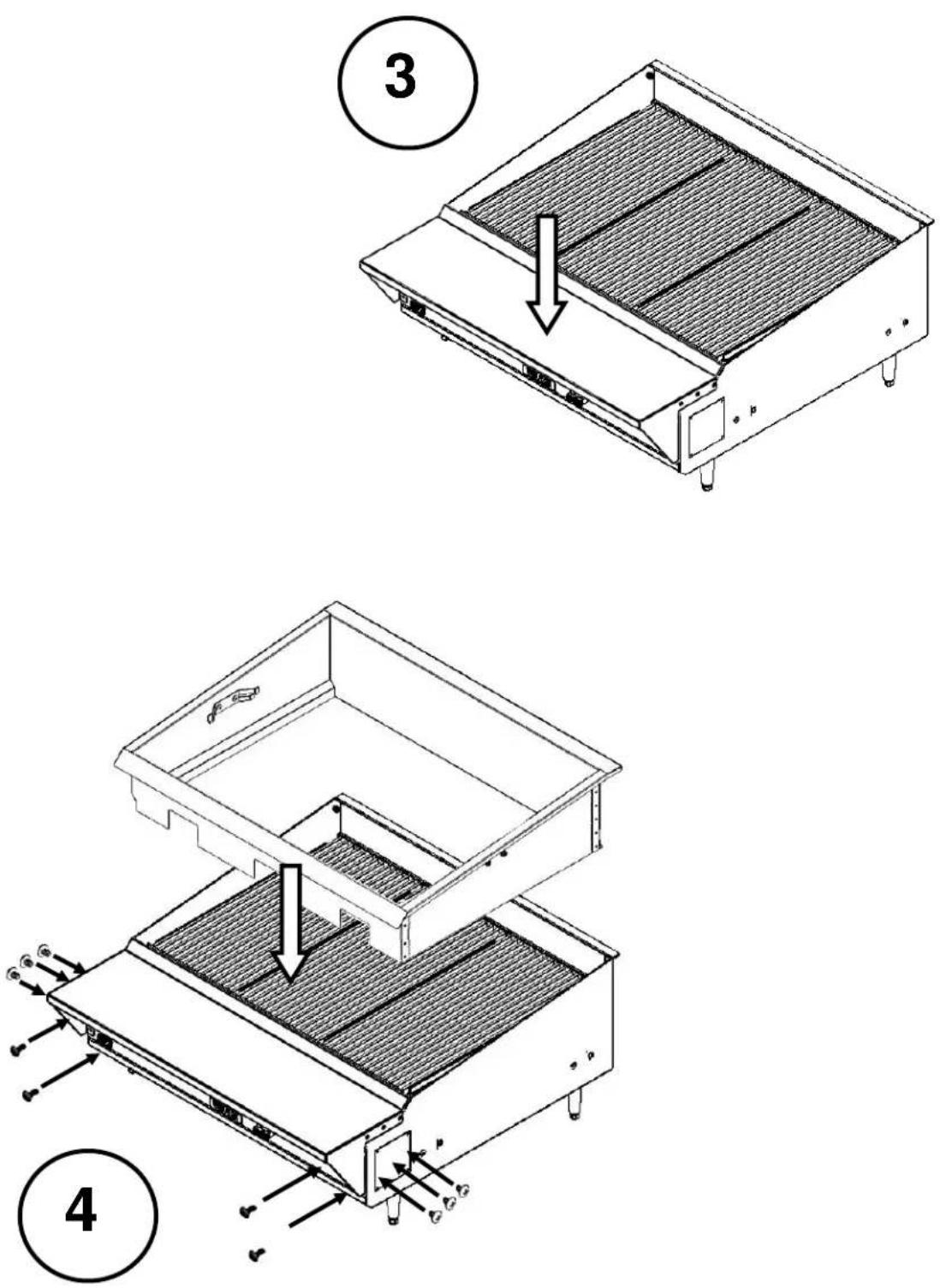
natural_image
3D technical diagram of a mechanical assembly with a rod inserted into a grid-patterned base (no text or symbols visible)101
natural_image
Close-up of a metallic mechanical component with no visible text or symbolsFig. 3

natural_image
Close-up of a mechanical component with no visible text or symbolsnatural_image
Exterior view of a stainless steel industrial kitchen or oven unit with control knobs and ventilation grilles (no visible text or symbols)MANUEL D'INSTALACTION ET D'EMPOI GRIL INFRAROUCE A GAZ

- MODELS
- IMPORTANT FOR YOUR SAFETY
- IMPORTANT
- FOR YOUR SAFETY
- WARNING
- INSTALLATION, OPERATION AND CARE OF GAS COUNTERTOP CHARBROILERS
- GENERAL
- INSTALLATION
- UNPACKING
- LOCATION
- INSTALLATION CODES AND STANDARDS
- The Charbroiler must be installed in accordance with:
- NOTE: In the Commonwealth of Massachusetts
- KEY COMPONENTS
- LEVELING
- VENTILATION HOOD
- GAS CONNECTION
- GAS PRESSURE REGULATOR INSTALLATION
- CASTER EQUIPPED CHARBROILERS
- OPERATION
- BURNER LIGHTING
- LIGHTING BURNER WITH SPARK IGNITER
- LIGHTING BURNER MANUALLY
- TO COMPLETELY SHUTDOWN THE BURNERS
- PREHEATING THE CHARBROILER
- CLEANING
- DAILY
- WEEKLY
- MAINTENANCE
- VENT SYSTEM
- LUBRICATION
- EMITTER PANELS
- SERVICE
- ACCESSORY INSTALLATION
- MANUEL D'INSTALACTION ET D'EMPOI GRIL INFRAROUCE A GAZ
Brand : Vulcan
Model : VTEC36
Category : Grill