MIC2125/6 - Carte de démonstration Microchip - Free user manual and instructions
Find the device manual for free MIC2125/6 Microchip in PDF.

User questions about MIC2125/6 Microchip
0 question about this device. Answer the ones you know or ask your own.
Ask a new question about this device
Download the instructions for your Carte de démonstration in PDF format for free! Find your manual MIC2125/6 - Microchip and take your electronic device back in hand. On this page are published all the documents necessary for the use of your device. MIC2125/6 by Microchip.
USER MANUAL MIC2125/6 Microchip
Note the following details of the code protection feature on Microchip devices:
• Microchip products meet the specification contained in their particular Microchip Data Sheet.
- Microchip believes that its family of products is one of the most secure families of its kind on the market today, when used in the intended manner and under normal conditions.
- There are dishonest and possibly illegal methods used to breach the code protection feature. All of these methods, to our knowledge, require using the Microchip products in a manner outside the operating specifications contained in Microchip's Data Sheets. Most likely, the person doing so is engaged in theft of intellectual property.
• Microchip is willing to work with the customer who is concerned about the integrity of their code.
- Neither Microchip nor any other semiconductor manufacturer can guarantee the security of their code. Code protection does not mean that we are guaranteeing the product as "unbreakable."
Code protection is constantly evolving. We at Microchip are committed to continuously improving the code protection features of our products. Attempts to break Microchip's code protection feature may be a violation of the Digital Millennium Copyright Act. If such acts allow unauthorized access to your software or other copyrighted work, you may have a right to sue for relief under that Act.
Information contained in this publication regarding device applications and the like is provided only for your convenience and may be superseded by updates. It is your responsibility to ensure that your application meets with your specifications. MICROCHIP MAKES NO REPRESENTATIONS OR WARRANTIES OF ANY KIND WHETHER EXPRESS OR IMPLIED, WRITTEN OR ORAL, STATUTORY OR OTHERWISE, RELATED TO THE INFORMATION, INCLUDING BUT NOT LIMITED TO ITS CONDITION, QUALITY, PERFORMANCE, MERCHANTABILITY OR FITNESS FOR PURPOSE. Microchip disclaims all liability arising from this information and its use. Use of Microchip devices in life support and/or safety applications is entirely at the buyer's risk, and the buyer agrees to defend, indemnify and hold harmless Microchip from any and all damages, claims, suits, or expenses resulting from such use. No licenses are conveyed, implicitly or otherwise, under any Microchip intellectual property rights unless otherwise stated.
Trademarks
The Microchip name and logo, the Microchip logo, Adaptec, AnyRate, AVR, AVR logo, AVR Freaks, BesTime, BitCloud, chipKIT, chipKIT logo, CryptoMemory, CryptoRF, dsPIC, FlashFlex, flexPWR, HELDO, IGLOO, JukeBlox, KeeLoq, Kleer, LANCheck, LinkMD, maXStylus, maXTouch, MediaLB, megaAVR, Microsemi, Microsemi logo, MOST, MOST logo, MPLAB, OptoLyzer, PackeTime, PIC, picoPower, PICSTART, PIC32 logo, PolarFire, Prochip Designer, QTouch, SAM-BA, SenGenuity, SpyNIC, SST, SST Logo, SuperFlash, Symmetricom, SyncServer, Tachyon, TempTrackr, TimeSource, tinyAVR, UNI/O, Vectron, and XMEGA are registered trademarks of Microchip Technology Incorporated in the U.S.A. and other countries.
APT, ClockWorks, The Embedded Control Solutions Company, EtherSynch, FlashTec, Hyper Speed Control, HyperLight Load, IntelliMOS, Libero, motorBench, mTouch, Powermite 3, Precision Edge, ProASIC, ProASIC Plus, ProASIC Plus logo, Quiet-Wire, SmartFusion, SyncWorld, Temux, TimeCesium, TimeHub, TimePictra, TimeProvider, Vite, WinPath, and ZL are registered trademarks of Microchip Technology Incorporated in the U.S.A.
Adjacent Key Suppression, AKS, Analog-for-the-Digital Age, Any Capacitor, AnyIn, AnyOut, BlueSky, BodyCom, CodeGuard, CryptoAuthentication, CryptoAutomotive, CryptoCompanion, CryptoController, dsPICDEM, dsPICDEM.net, Dynamic Average Matching, DAM, ECAN, EtherGREEN, In-Circuit Serial Programming, ICSP, INICnet, Inter-Chip Connectivity, JitterBlocker, KleerNet, KleerNet logo, memBrain, Mindi, MiWi, MPASM, MPF, MPLAB Certified logo, MPLIB, MPLINK, MultiTRAK, NetDetach, Omniscient Code Generation, PICDEM, PICDEM.net, PICkit, PICtail, PowerSmart, PureSilicon, QMatrix, REAL ICE, Ripple Blocker, SAM-ICE, Serial Quad I/O, SMART-I.S., SQI, SuperSwitcher, SuperSwitcher II, Total Endurance, TSHARC, USBCheck, VariSense, ViewSpan, WiperLock, Wireless DNA, and ZENA are trademarks of Microchip Technology Incorporated in the U.S.A. and other countries.
SQTP is a service mark of Microchip Technology Incorporated in the U.S.A. The Adaptec logo, Frequency on Demand, Silicon Storage Technology, and Symmcom are registered trademarks of Microchip Technology Inc. in other countries. GestIC is a registered trademark of Microchip Technology Germany II GmbH & Co. KG, a subsidiary of Microchip Technology Inc., in other countries. All other trademarks mentioned herein are property of their respective companies.
© 2015-2019, Microchip Technology Incorporated, All Rights Reserved.
ISBN: 978-1-5224-4698-9
For information regarding Microchip's Quality Management Systems, please visit www.microchip.com/quality.
Table of Contents
Preface 5
Chapter 1. Product Overview ...... 9
1.1 Introduction 9
1.2 MIC2125/6 Short Overview 9
1.3 What is the MIC2125/6 Demonstration Board? 10
1.4 MIC2125/6 Demonstration Board Kit Contents 14
Chapter 2. Installation and Operation .... 15
2.1 Overview 15
2.2 Getting Started 15
Appendix A. Schematics and Layouts 17
A.1 Introduction 17
A.2 Board – Schematic (16-Lead QFN Part) 18
A.3 Board – Top Layer 19
A.4 Board – Mid Layer 1 (Ground Plane) 19
A.5 Board - Mid Layer 2 ...... 20
A.6 Board – Bottom Layer 20
Appendix B. Bill of Materials (BOM).... 21
Worldwide Sales and Service 24
NOTES:
Preface
NOTICE TO CUSTOMERS
All documentation becomes dated, and this manual is no exception. Microchip tools and documentation are constantly evolving to meet customer needs, so some actual dialogs and/or tool descriptions may differ from those in this document. Please refer to our website (www.microchip.com) to obtain the latest documentation available.
Documents are identified with a "DS" number. This number is located on the bottom of each page, in front of the page number. The numbering convention for the DS number is "DSXXXXXXXXA", where "XXXXXXXXX" is the document number and "A" is the revision level of the document.
For the most up-to-date information on development tools, see the MPLAB ^® IDE online help. Select the Help menu, and then Topics to open a list of available online help files.
INTRODUCTION
This chapter contains general information that will be useful to know before using the MIC2125/6 Demonstration Board. Items discussed in this chapter include:
- Document Layout
• Conventions Used in this Guide
• Recommended Reading
• The Microchip Website - Customer Support
• Document Revision History
DOCUMENT LAYOUT
This document describes how to use the MIC2125/6 Demonstration Board as a development tool to emulate and debug firmware on a target board, as well as how to program devices. The document is organized as follows:
- Chapter 1. "Product Overview" – Provides important information about the MIC2125/6 Demonstration Board and shows the hardware details of its components.
- Chapter 2. "Installation and Operation" – Includes instructions on how to use, power and test the MIC2125/6 Demonstration Board.
- Appendix A. "Schematics and Layouts" – Shows the schematic and layout diagrams for the MIC2125/6 Demonstration Board.
- Appendix B. "Bill of Materials (BOM)" – Lists the parts used to build the MIC2125/6 Demonstration Board.
CONVENTIONS USED IN THIS GUIDE
This manual uses the following documentation conventions:
DOCUMENTATION CONVENTIONS
| Description Represents Examples | ||
| Arial font: | ||
| Italic characters Referenced books | mPLAB | ^ IDE User's Guide |
| Emphasized text ...is the only compiler... | ||
| Initial caps A window the Output | ut window | |
| A dialog the Settings dialog | ||
| A menu selection select Enable Programmer | ||
| Quotes A field name in a window or dialog | "Save project before build" | |
| Underlined, italic text with right angle bracket | A menu path File>Save | —— |
| Bold characters A dialog button | Click OK | |
| A tab | Click the Power tab | |
| N'Rnnnn | A number in verilog format, where N is the total number of digits, R is the radix and n is a digit. | 4'b0010, 2'hF1 |
| Text in angle brackets <> | A key on the keyboard | Press,, |
| Courier New font: | ||
| Plain Courier New | Sample source code | #define START |
| Filenames | autoexec.bat | |
| File paths | c:\mccl8\h | |
| Keywords | _asm, _endasm, static | |
| Command-line options | -Opa+, -Opa- | |
| Bit values | 0, 1 | |
| Constants | 0xFF, 'A' | |
| Italic Courier New | A variable argument | file.o, where file can be any valid filename |
| Square brackets [] | Optional arguments | mccl8 [options] file [options] |
| Curly brackets and pipe character: { | } | Choice of mutually exclusive arguments; an OR selection | errorlevel {0|1} |
| Ellipses... Replaces repeated text var_name [, | var_name...] | |
| Represents code supplied by user | ||
RECOMMENDED READING
This user's guide describes how to use the MIC2125/6 Demonstration Board. Another useful document is listed below. The following Microchip document is available and recommended as a supplemental reference resource:
- MIC2125/6 Data Sheet – “28V Synchronous Buck Controllers Featuring Adaptive ON-Time Control” (DS20005459)
THE MICROCHIP WEBSITE
Microchip provides online support via our website at www.microchip.com. This website is used as a means to make files and information easily available to customers. Accessible by using your favorite Internet browser, the website contains the following information:
- Product Support – Data sheets and errata, application notes and sample programs, design resources, user's guides and hardware support documents, latest software releases and archived software
- General Technical Support – Frequently Asked Questions (FAQs), technical support requests, online discussion groups, Microchip consultant program member listing
- Business of Microchip – Product selector and ordering guides, latest Microchip press releases, listing of seminars and events, listings of Microchip sales offices, distributors and factory representatives
CUSTOMER SUPPORT
Users of Microchip products can receive assistance through several channels:
• Distributor or Representative
- Local Sales Office
• Field Application Engineer (FAE)
- Technical Support
Customers should contact their distributor, representative or field application engineer (FAE) for support. Local sales offices are also available to help customers. A listing of sales offices and locations is included in the back of this document.
Technical support is available through the website at: http://www.microchip.com/support.
DOCUMENT REVISION HISTORY
Revision B (June 2019)
- Updated Figure 1-1: "Typical Application Circuit."
- Updated Appendix B. "Bill of Materials (BOM)".
Revision A (December 2015)
- Initial release of this document.
NOTES:
Chapter 1. Product Overview
1.1 INTRODUCTION
This chapter provides an overview of the MIC2125/6 Demonstration Board and covers the following topics:
• MIC2125/6 Short Overview
• What is the MIC2125/6 Demonstration Board?
• MIC2125/6 Demonstration Board Kit Contents
1.2 MIC2125/6 SHORT OVERVIEW
1.2.1 MIC2125/6 Key Features
The key features of the MIC2125/6 include:
- Hyper Speed Control ^ Architecture Enables: - High delta V operation ( V_IN = 28V and V_OUT = 0.6V )
- Any Capacitor™ Stable - 4.5V to 28V Input Voltage - Adjustable Output Voltage from 0.6V to 24V - 200 kHz to 750 kHz Programmable Switching Frequency - HyperLight Load ® (MIC2125)
• Hyper Speed Control (MIC2126)
- Enable Input and Power Good Output
• Built-in 5V Regulator for Single-Supply Operation - Programmable Current Limit and "Hiccup" Mode Short-Circuit Protection
- 7 ms Internal Soft Start, Internal Compensation and Thermal Shutdown
• Supports Safe Start-up into a Prebiased Output - -40°C to +125°C Junction Temperature Range
• 16-pin, 3 mm × 3 mm QFN Package
1.2.2 MIC2125/6 Overview
The MIC2125 and MIC2126 are constant frequency synchronous buck controllers featuring a unique adaptive on-time control architecture. The MIC2125/6 devices operate over an input voltage range from 4.5V to 28V and can be used to supply load current up to 25A. The output voltage is adjustable down to 0.6V with an accuracy of ±1%. The device operates with programmable switching frequency from 200 kHz to 750 kHz.
HyperLight Load architecture operates in Pulse-Skipping mode at light loads, but operates in Fixed-Frequency CCM mode from medium loads to heavy loads. HyperSpeed Control architecture operates in Fixed-Frequency CCM mode under all load conditions.
The basic parameters of the demonstration board are:
- Input: 5V to 25V
• Output: 0.6V to 5V at 20A
• 350 kHz Switching Frequency (adjustable from 200 kHz to 750 kHz)
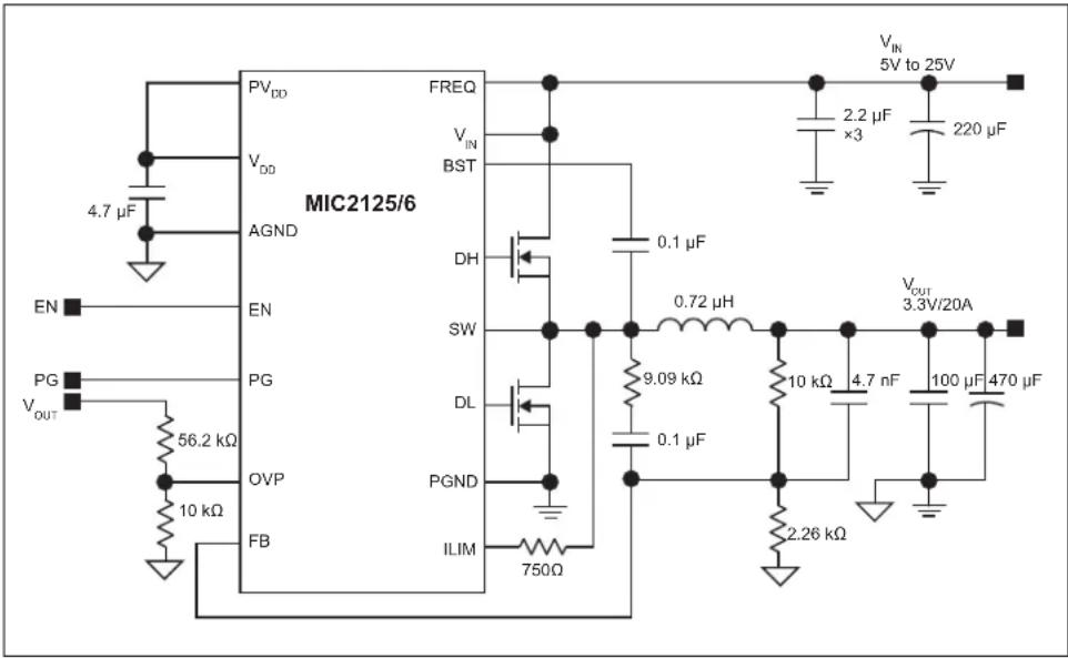
text_image
MIC2125/6 PVDD VDD AGND EN PG VOUT 56.2 kΩ 10 kΩ FB FREQ VIN BST DH SW DL PGND ILIM 750Ω 0.1 μF 0.72 μH 9.09 kΩ 0.1 μF 2.26 kΩ VIN 5V to 25V 2.2 μF ×3 220 μF VOUT 3.3V/20A 10 kΩ 4.7 nF 100 μF 470 μFFIGURE 1-1: Typical Application Circuit.
1.3 WHAT IS THE MIC2125/6 DEMONSTRATION BOARD?
The MIC2125/6 Demonstration Board has been developed to demonstrate the capabilities of the MIC2125/6 devices with two adaptive on-time control architectures:
• Hyper Speed Control (MIC2126)
• HyperLight Load (MIC2125)
1.3.1 Requirements
The MIC2125 and MIC2126 Demonstration Boards require only a single power supply with at least 10A current capability. The MIC2125/6 each have an internal V_DD LDO, so no external linear regulator is required to power the internal biasing of the IC. In applications with V_IN < +5.5V , V_DD should be tied to V_IN to bypass the internal linear regulator. The output load can either be a passive or active load.
1.3.2 Precautions
The MIC2125/6 Demonstration Boards do not have reverse polarity protection. Applying a negative voltage to the V_IN and GND terminals may damage the device. The maximum V_IN of the board is rated at 25V.
| CAUTION |
| Exceeding 25V on the V_IN pin can damage the low-side power MOSFETs. |
1.3.3 Feedback Resistors
The output voltage on the MIC2125/6 Demonstration Boards, which are preset to 1.2V, is determined by the feedback divider:
EQUATION 1-1:
$$ \mathrm{V} _ {\text {OUT}} \quad \mathrm{V} _ {\text {REF}} \times = (1 \frac {\mathrm{R} 1}{\mathrm{R} _ {\text {BOTTOM}}} +) $$
Where:
| V_REF | 0.6V |
| R_BOTTOM | R4 = 0.8V |
| R5 = 1.0V | |
| R6 = 1.2V | |
| R7 = 1.5V | |
| R8 = 1.8V | |
| R9 = 2.5V | |
| R10 = 3.3V | |
| R11 = 5V | |
| OPEN = 0.6V |
All other voltages not listed above can be set by modifying the R_BOTTOM value according to Equation 1-2.
EQUATION 1-2:
$$ R _ {\text { BOTTOM }} = \frac {R 1 \times V _ {\text { REF }}}{V _ {\text { OUT }} - V _ {\text { REF }}} $$
Note that the output voltage should not be set to exceed 5V due to the 6.3V voltage rating on the output capacitors.
1.3.4 SW Node
Test point J1 ( V_SW ) is placed for monitoring the switching waveform, one of the most critical waveforms for the converter.
1.3.5 Current Limit
The MIC2125/6 devices use the R_DS(ON) of the low-side MOSFET and an external resistor connected from the ILIM pin to the SW node to determine the current limit.
In each switching cycle of the MIC2125/6, the inductor current is sensed by monitoring the low-side MOSFET in the off period. The sensed voltage V_(ILIM) is compared with the Power Ground ( P_GND ) after a blanking time of 150 ns. In this way, the drop voltage over resistor R17 ( V_CL ) is compared with the drop over the bottom FET, generating the short current limit. The small capacitor (C18) connected from the ILIM pin to PGND filters the switching node ringing during the off-time, allowing a better short current limit measurement. The time constant created by R17 and C18 should be much less than the minimum off-time.
The V_CL drop allows the programming of the short current limit through the value of the resistor ( R_CL ). If the absolute value of the voltage drop on the bottom FET is greater than V_CL , then V_(ILIM) is lower than P_GND and a short-circuit event is triggered. A hiccup cycle is then generated to treat the short-circuit event.
The hiccup sequence, including the soft start, reduces the stress on the switching FETs and protects the load and supply in severe short conditions.

text_image
CONTROL LOGIC TIMER SOFT START CL DETECTION V_IN DH Q1 SW DL Q3 PGND ILIM C1, C2, C3, C4 L1 R17 C13, C14 I_CL C17FIGURE 1-2: MIC2125/6 Current-Limiting Circuit.
The short-circuit current limit can be programmed by using the following formula:
EQUATION 1-3:
| R17 = (ICLIM + ΔPP × 0.5) RDSON(→VCL) | |
| ICLIM | Desired Current Limit |
| ΔPP | Inductor Current Peak-to-Peak |
| RDS(ON) | On-Resistance of Low-Side Power MOSFET |
| VCL | Current-Limit Threshold (Typical Value is 14 mV) |
| ICL | Current-Limit Source Current (Typical Value is 36 μA) |
The MOSFET R_DS(ON) varies 30% to 40% with temperature; therefore, it is recommended to add a 50% margin to R17 in the equation above to avoid false current limiting due to any rise in MOSFET junction temperature. It is also recommended to connect the SW pin directly to the drain of the low-side MOSFET to accurately sense the MOSFET's R_DS(ON) .
1.3.6 Loop Gain Measurement
The resistor, R14, is placed in series with the regulator feedback path. The control loop gain can be measured by connecting an impedance analyzer across the resistor and selecting a resistor value in between 20Ω to 50Ω.
1.3.7 Setting the Switching Frequency
The MIC2125/6 devices are adjustable frequency, synchronous buck controllers that feature a unique adaptive on-time control architecture. The switching frequency can be adjusted between 200 kHz and 750 kHz by changing the resistor divider network, which consists of R19 and R20.
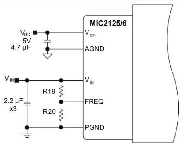
text_image
MIC2125/6 VDD 5V 4.7 μF AGND VIN 2.2 μF x3 R19 R20 FREQ PGNDFIGURE 1-3: Switching Frequency Adjustment.
The following formula gives the estimated switching frequency:
EQUATION 1-4:
$$ f _ {S W A D J (} \quad f _ {O} \quad \frac {R 2 0}{R 1 9 R 2 0 +} \times = $$
Where:
$$ f _ {O} \quad \text { Switching Frequency when R19 is 100 k\Omega and R20 is open; f_{O} is typically 750 kHz.} $$
For more precise setting, it is recommended to use the following graph.
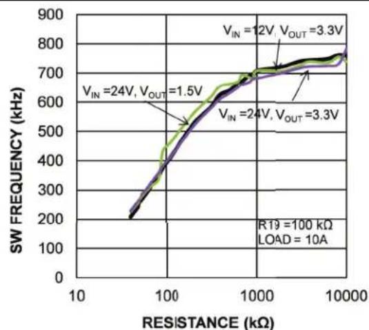
line
| RESISTANCE (kΩ) | SW FREQUENCY (kHz) | | --------------- | ------------------ | | 10 | 200 | | 100 | 500 | | 1000 | 700 | | 10000 | 750 |FIGURE 1-4: Switching Frequency vs. R20.
The evaluation board design is optimized for a switching frequency of 350 kHz. If the switching frequency is programmed to either the lower end or higher end, the design needs optimization.
1.4 MIC2125/6 DEMONSTRATION BOARD KIT CONTENTS
This MIC2125/6 Demonstration Board kit includes the following items:
- MIC2125/6 Demonstration Board (MIC2125YML-20A-EV or MIC2126YML-20A-EV)
- Important Information Sheet
Chapter 2. Installation and Operation
2.1 OVERVIEW
The following sections describe how to use the MIC2125/6 Demonstration Board to fully evaluate and demonstrate the capabilities of the MIC2125/6 devices.
2.2 GETTING STARTED
2.2.1 V IN Supply
Connect a supply to the V_IN and GND terminals, paying careful attention to the polarity and the supply range (5V < V_IN < 25V). Monitor I_IN with a current meter and input voltage at V_IN , and GND terminals with a voltmeter. Do not apply power until (see Section 2.2.4 “Turn On the Power”).
2.2.2 Connect Load and Monitor Output
Connect a load to the V_OUT and GND terminals. The load can be either a passive (resistive) or an active (as in an electronic load) type. A current meter may be placed between the V_OUT terminal and the load to monitor the output current. Ensure the output voltage is monitored at the V_OUT terminal.
2.2.3 Enable Input
The EN pin has an on-board 100 kΩ pull-up resistor (R22) to V_IN that allows the output to be turned on when V_DD exceeds its UVLO threshold. An EN connector is provided on the evaluation board for users to easily access the enable feature. Applying an external logic signal on the EN pin to pull it low, or using a jumper to short the EN pin to GND, will shut off the output of the MIC2125/6 Demonstration Board.
2.2.4 Turn On the Power
Turn on the V_IN supply and verify that the output voltage is regulated to 3.3V.
NOTES:
Appendix A. Schematics and Layouts
A.1 INTRODUCTION
This appendix contains the following schematics and layouts for the MIC2125/6 Demonstration Board (MIC2125YML-20A-EV or MIC2126YML-20A-EV):
• Board – Schematic (16-Lead QFN Part)
- Board – Top Layer
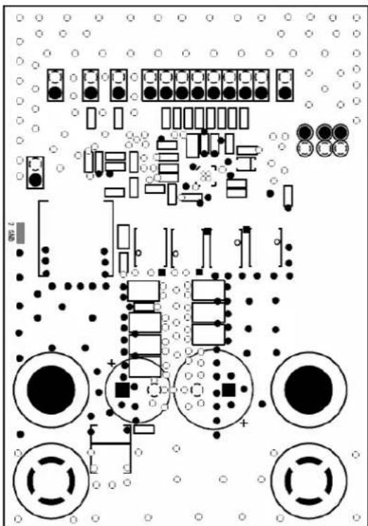
- Board – Mid Layer 1 (Ground Plane)
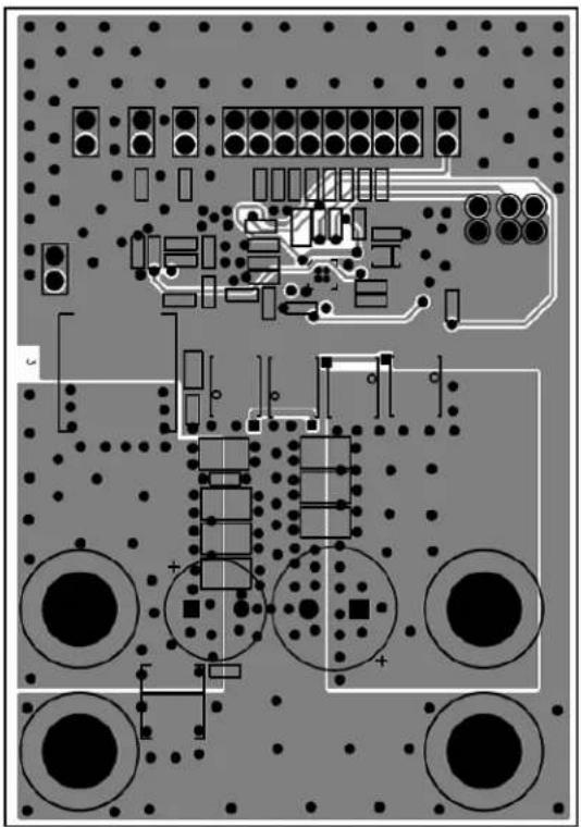
- Board – Mid Layer 2
- Board – Bottom Layer
A.2 BOARD - SCHEMATIC (16-LEAD QFN PART)
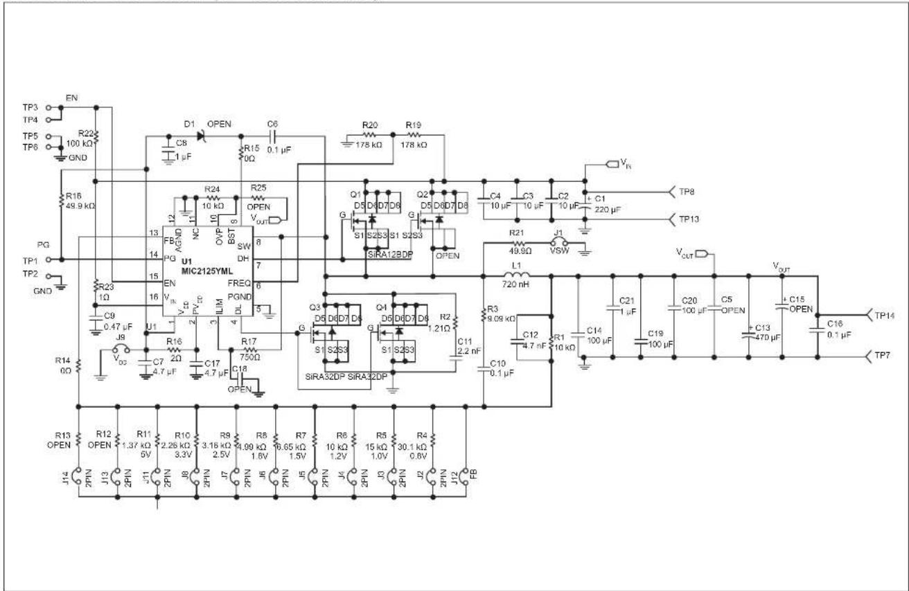
text_image
TP3 TP4 TP5 TP6 EN R22 100 kΩ GND R16 49.9 kΩ PG TP1 TP2 GND R23 1Ω C9 0.47 μF J8 VDD R16 C7 2Ω VCC R14 0Ω R13 OPEN J14 2PIN J13 2PIN J11 2PIN J8 2PIN J7 2PIN J6 2PIN J5 2PIN J4 2PIN J3 2PIN J2 2PIN J12 RB D1 OPEN C6 C8 1 μF R15 0.1 μF R24 10 kΩ R25 OPEN VOUT NC OVP BST SW DH 8 7 U1 MIC2125YML FREQ PGND 6 5 VCC 4.7 μF 3 ILM 4 DL 3 Q3 D6 D7 D8 Q1 D6 D7 D8 Q2 D6 D7 D8 Q3 D6 D7 D8 Q4 D6 D7 D8 Q5 D6 D7 D8 Q6 D6 D7 D8 Q7 D6 D7 D8 Q8 D6 D7 D8 Q9 D6 D7 D8 Q10 D6 D7 D8 Q11 D6 D7 D8 Q12 D6 D7 D8 Q13 D6 D7 D8 Q14 D6 D7 D8 Q15 D6 D7 D8 Q16 D6 D7 D8 Q17 D6 D7 D8 Q18 D6 D7 D8 Q19 D6 D7 D8 Q20 D6 D7 D8 Q21 D6 D7 D8 Q22 D6 D7 D8 Q23 D6 D7 D8 Q24 D6 D7 D8 Q25 D6 D7 D8 Q26 D6 D7 D8 Q27 D6 D7 D8 Q28 D6 D7 D8 Q29 D6 D7 D8 Q30 D6 D7 D8 Q31 D6 D7 D8 Q32 D6 D7 D8 Q33 D6 D7 D8 Q34 D6 D7 D8 Q35 D6 D7 D8 Q36 D6 D7 D8 Q37 D6 D7 D8 Q38 D6 D7 D8 Q39 D6 D7 D8 Q40 D6 D7 D8 Q41 D6 D7 D8 Q42 D6 D7 D8 Q43 D6 D7 D8 Q44 D6 D7 D8 Q45 D6 D7 D8 Q46 D6 D7 D8 Q47 D6 D7 D8 Q48 D6 D7 D8 Q49 D6 D7 D8 Q50 D6 D7 D8 Q51 D6 D7 D8 Q52 D6 D7 D8 Q53 D6 D7 D8 Q54 D6 D7 D8 Q55 D6 D7 D8 Q56 D6 D7 D8 Q57 D6 D7 D8 Q58 D6 D7 D8 Q59 D6 D7 D8 Q60 D6 D7 D8 Q61 D6 D7 D8 Q62 D6 D7 D8 Q63 D6 D7 D8 Q64 D6 D7 D8 Q65 D6 D7 D8 Q66 TIP14 TP7 Q1 S1 S2S3 S1 S2S3 SIR A12 BDP OPEN L1 720 nH R3 9.09 kΩ C21 1 μF C19 100 μF C5 100 μF C13 470 μF C15 OPEN C16 0.1 μF TP14 Q2 S1 S2S3 S1 S2S3 SIR A32DP SIR A32DP R1 4.7 nF R10 10 kΩ R9 3.15 kΩ R9 4.90 kΩ R8 0.65 kΩ R7 10 kΩ R6 15 kΩ R5 30.1 kΩ R4 0.6V RBA.3 BOARD - TOP LAYER
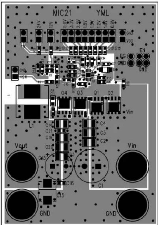
text_image
MIC21 YML 24V 12V 5.0V 3.5V 2.5V 1.8V 1.5V 1.2V 1.0V 0.9V GND VDD EN FCC GND GND C21 C14 R1 R2 Q4 Q3 Q1 Q2 R6 L1 C14 C21 C19 C20 C3+ C16 C15 Vin Vout GND GNDA.4 BOARD – MID LAYER 1 (GROUND PLANE)
natural_image
Pure electrical circuit lines without any symbolsA.5 BOARD - MID LAYER 2
natural_image
Top-down schematic of a printed circuit board with components and connections (no readable text or symbols)A.6 BOARD - BOTTOM LAYER
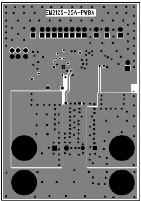
text_image
EM2125-25A-PWBAAppendix B. Bill of Materials (BOM)
TABLE B-1: BILL OF MATERIALS (BOM)
| Qty. | Reference Description Manufacturer Part Number | |||
| 1 C1 | 220 μF/35V | Aluminum Capacitor Nichicon Corporation UHE1V2 | 21MPD6 | |
| 3 C2 | C3, C4 10 μF/35V Ceramic Capacitor, X7R, Size 1210 Murata | Electronic® | GRM32ER7YA106K | |
| TDK Corporation | C3216X7R1V106K160AC | |||
| 3 | C14, C19, C20 | 100 μF/6.3V Ceramic Capacitor, X5R, Size 1210 | Murata Electronics | GRM32ER60J107M |
| AVX Corporation | 12106D107KAT2A | |||
| TDK Corporation | C3225X5R0J107M250AC | |||
| 3 C6 | C16, C10 0.1 μF/50V Ceramic Capacitor, X7R, Size 0603 | Murata Electronics GRM188R71H104K | ||
| AVX Corporation | 06035C104KAT2A | |||
| TDK Corporation | C1608X7R1H104K | |||
| 2 | C7, C17 | 4.7 μF/10V Ceramic Capacitor, X7R, Size 0603 | Murata Electronics | GRM188C71A475K |
| AVX Corporation | 0603ZD475KAT2A | |||
| TDK Corporation | CGB3B1X5R1A475K | |||
| 2 C8 | C21 1 μF/6.3V Ceramic Capacitor, X7R, Size 0603 Murata Electronics GRM188R70J105K | |||
| AVX Corporation | 06036C105KAT2A | |||
| TDK Corporation | C1608X5R0J105K | |||
| 1 | C9 | 0.47 μF/50V Ceramic Capacitor, X7R, Size 0805 | Murata Electronics | GRM21BR71H474K |
| AVX Corporation | 08055C474KAT2A | |||
| 1 | C11 | 2.2 nF/100V Ceramic Capacitor, X7R, Size 0603 | Murata Electronics | GRM188R72A222K |
| AVX Corporation | 06031C222KAT2A | |||
| TDK Corporation | C1608X7R2A222K | |||
| 1 | C12 | 4.7 nF/50V Ceramic Capacitor, C0G, Size 0603 | Murata Electronics | GRM1885C1H472J |
| AVX Corporation | 06035A471JAT2A | |||
| TDK Corporation | C1608C0G1H471J080AA | |||
| 1 | C13 | 470 μF/6.3V, 7 mΩ, OSCON | SANYO | 6SEPC470MX |
| 1 | C15 (OPEN) | 470 μF/6.3V POSCAP | SANYO | 6TPB470M |
| 1 | C5 (OPEN) | 100 μF/6.3V Ceramic Capacitor, X5R, Size 1210 | Murata Electronics | GRM32ER60J107M |
| 1 | C18 (OPEN) | 10 pF/50V Ceramic Capacitor, C0G, Size 0603 | Murata Electronics | GRM1885C1H100J |
| AVX Corporation | 06035A100JAT2A | |||
| D1 (OPEN) | ||||
| 1 L1 | 0.72 μH, 35 ASAT, 22 ARMS for 40°C Rise | Wurth Elektronik | 744325072 | |
| 1 | Q1 | MOSFET, N-CH, Power SO-8 | Vishay Siliconix | SiRA12BDP |
| 2 | Q3, Q4 | MOSFET, N-CH, Power SO-8 | Vishay Siliconix | SiRA32DP |
| 1 | R1 | 10 kΩ Resistor, Size 0603, 1% | Vishay/Dale | CRCW060310K0FKEA |
| 1 | R2 | 1.21Ω Resistor, Size 0805, 5% | Vishay/Dale | CRCW08051R21FKEA |
| 1 | R3 | 9.09 kΩ, 1%, 1/10W, 0603 | Vishay/Dale | CRCW06039K09FKEA |
| 1 | R4 | 30.1 kΩ Resistor, Size 0603, 1% | Vishay/Dale | CRCW060330K1FKEA |
| Qty. | Reference | Description | Manufacturer | Part Number |
| 1 | R5 | 15 kΩ Resistor, Size 0603, 1% | Vishay/Dale | CRCW060315K0FKEA |
| 1 | R6 | 10 kΩ Resistor, Size 0603, 1% | Vishay/Dale | CRCW060310K0FKEA |
| 1 | R7 | 6.65 kΩ Resistor, Size 0603, 1% | Vishay/Dale | CRCW06036K65FKEA |
| 1 | R8 | 4.99 kΩ Resistor, Size 0603, 1% | Vishay/Dale | CRCW06034K99FKEA |
| 1 | R9 | 3.16 kΩ Resistor, Size 0603, 1% | Vishay/Dale | CRCW06033K16FKEA |
| 1 | R10 | 2.26 kΩ Resistor, Size 0603, 1% | Vishay/Dale | CRCW06032K26FKEA |
| 1 | R11 | 1.37 kΩ Resistor, Size 0603, 1% | Vishay/Dale | CRCW06031K37FKEA |
| R12, R13,R25 (OPEN) | ||||
| 2 | R14, R15 | 0Ω Resistor, Size 0603, 5% | Vishay/Dale | CRCW06030000Z0EA |
| 1 | R16 | 2Ω Resistor, Size 0603, 1% | Vishay/Dale | CRCW06032R00FKEA |
| 1 | R17 | 750Ω Resistor, Size 0603, 1% | Vishay/Dale | CRCW0603750RFKEA |
| 1 | R18 | 49.9 kΩ Resistor, Size 0603, 1% | Vishay/Dale | CRCW060349K9FKEA |
| 2 | R19, R20 | 178 kΩ Resistor, Size 0603, 1% | Vishay/Dale | CRCW0603178KFKEA |
| 1 | R21 | 49.9Ω Resistor, Size 0603, 1% | Vishay/Dale | CRCW060349R9FKEA |
| 1 | R22 | 100 kΩ Resistor, Size 0603, 1% | Vishay/Dale | CRCW0603100KFKEA |
| 1 | R24 | 10 kΩ Resistor, Size 0603, 1% | Vishay/Dale | CRCW060310K0FKEA |
| 1 | R23 | 1Ω Resistor, Size 0603, 1% | Vishay/Dale | CRCW06031R00FKEA |
| 1 U | 1 28V Synchronous Buck Controllers FeaturingAdaptive On-Time Control | MicrochipTechnology Inc. | MIC2125YML | |
| MIC2126YML | ||||
Note: The components listed in this Bill of Materials are representative of the PCB assembly. The released BOM used in manufacturing uses all RoHS-compliant components.
NOTES:
Worldwide Sales and Service
AMERICAS
Corporate Office
2355 West Chandler Blvd.
Chandler, AZ 85224-6199
Tel: 480-792-7200
Fax: 480-792-7277
Technical Support:
http://www.microchip.com/
support
Web Address:
www.microchip.com
Atlanta
Duluth, GA
Tel: 678-957-9614
Fax: 678-957-1455
Austin, TX
Tel: 512-257-3370
Boston
Westborough, MA
Tel: 774-760-0087
Fax: 774-760-0088
Chicago
Itasca, IL
Tel: 630-285-0071
Fax: 630-285-0075
Dallas
Addison, TX
Tel: 972-818-7423
Fax: 972-818-2924
Detroit
Novi, MI
Tel: 248-848-4000
Houston, TX
Tel: 281-894-5983
Indianapolis
Noblesville, IN
Tel: 317-773-8323
Fax: 317-773-5453
Tel: 317-536-2380
Los Angeles
Mission Viejo, CA
Tel: 949-462-9523
Fax: 949-462-9608
Tel: 951-273-7800
Raleigh, NC
Tel: 919-844-7510
New York, NY
Tel: 631-435-6000
San Jose, CA
Tel: 408-735-9110
Tel: 408-436-4270
Canada - Toronto
Tel: 905-695-1980
Fax: 905-695-2078
ASIA/PACIFIC
Australia - Sydney
Tel: 61-2-9868-6733
China - Beijing
Tel: 86-10-8569-7000
China - Chengdu
Tel: 86-28-8665-5511
China - Chongqing
Tel: 86-23-8980-9588
China - Dongguan
Tel: 86-769-8702-9880
China - Guangzhou
Tel: 86-20-8755-8029
China - Hangzhou
Tel: 86-571-8792-8115
China - Hong Kong SAR
Tel: 852-2943-5100
China - Nanjing
Tel: 86-25-8473-2460
China - Qingdao
Tel: 86-532-8502-7355
China - Shanghai
Tel: 86-21-3326-8000
China - Shenyang
Tel: 86-24-2334-2829
China - Shenzhen
Tel: 86-755-8864-2200
China - Suzhou
Tel: 86-186-6233-1526
China - Wuhan
Tel: 86-27-5980-5300
China - Xian
Tel: 86-29-8833-7252
China - Xiamen
Tel: 86-592-2388138
China - Zhuhai
Tel: 86-756-3210040
ASIA/PACIFIC
India - Bangalore
Tel: 91-80-3090-4444
India - New Delhi
Tel: 91-11-4160-8631
India - Pune
Tel: 91-20-4121-0141
Japan - Osaka
Tel: 81-6-6152-7160
Japan - Tokyo
Tel: 81-3-6880-3770
Korea - Daegu
Tel: 82-53-744-4301
Korea - Seoul
Tel: 82-2-554-7200
Malaysia - Kuala Lumpur
Tel: 60-3-7651-7906
Malaysia - Penang
Tel: 60-4-227-8870
Philippines - Manila
Tel: 63-2-634-9065
Singapore
Tel: 65-6334-8870
Taiwan - Hsin Chu
Tel: 886-3-577-8366
Taiwan - Kaohsiung
Tel: 886-7-213-7830
Taiwan - Taipei
Tel: 886-2-2508-8600
Thailand - Bangkok
Tel: 66-2-694-1351
Tel: 43-7242-2244-39
Fax: 43-7242-2244-393
Denmark - Copenhagen
Tel: 45-4450-2828
Fax: 45-4485-2829
Finland - Espoo
Tel: 358-9-4520-820
France - Paris
Tel: 33-1-69-53-63-20
Fax: 33-1-69-30-90-79
Germany - Garching
Tel: 49-8931-9700
Germany - Haan
Tel: 49-2129-3766400
Germany - Heilbronn
Tel: 49-7131-72400
Germany - Karlsruhe
Tel: 49-721-625370
Germany - Munich
Tel: 49-89-627-144-0
Fax: 49-89-627-144-44
Germany - Rosenheim
Tel: 49-8031-354-560
Israel - Ra'anana
Tel: 972-9-744-7705
Italy - Milan
Tel: 39-0331-742611
Fax: 39-0331-466781
Italy - Padova
Tel: 39-049-7625286
Netherlands - Drunen
Tel: 31-416-690399
Fax: 31-416-690340
Norway - Trondheim
Tel: 47-7288-4388
Poland - Warsaw
Tel: 48-22-3325737
Romania - Bucharest
Tel: 40-21-407-87-50
Spain - Madrid
Tel: 34-91-708-08-90
Fax: 34-91-708-08-91
Sweden - Gothenberg
Tel: 46-31-704-60-40
Sweden - Stockholm
Tel: 46-8-5090-4654
UK - Wokingham
Tel: 44-118-921-5800
Fax: 44-118-921-5820