MCP8063 - Carte de démonstration Microchip - Free user manual and instructions
Find the device manual for free MCP8063 Microchip in PDF.

User questions about MCP8063 Microchip
0 question about this device. Answer the ones you know or ask your own.
Ask a new question about this device
Download the instructions for your Carte de démonstration in PDF format for free! Find your manual MCP8063 - Microchip and take your electronic device back in hand. On this page are published all the documents necessary for the use of your device. MCP8063 by Microchip.
USER MANUAL MCP8063 Microchip
Demonstration Board Kit
User's Guide
Note the following details of the code protection feature on Microchip devices:
• Microchip products meet the specification contained in their particular Microchip Data Sheet.
- Microchip believes that its family of products is one of the most secure families of its kind on the market today, when used in the intended manner and under normal conditions.
- There are dishonest and possibly illegal methods used to breach the code protection feature. All of these methods, to our knowledge, require using the Microchip products in a manner outside the operating specifications contained in Microchip's Data Sheets. Most likely, the person doing so is engaged in theft of intellectual property.
• Microchip is willing to work with the customer who is concerned about the integrity of their code.
- Neither Microchip nor any other semiconductor manufacturer can guarantee the security of their code. Code protection does not mean that we are guaranteeing the product as "unbreakable."
Code protection is constantly evolving. We at Microchip are committed to continuously improving the code protection features of our products. Attempts to break Microchip's code protection feature may be a violation of the Digital Millennium Copyright Act. If such acts allow unauthorized access to your software or other copyrighted work, you may have a right to sue for relief under that Act.
Information contained in this publication regarding device applications and the like is provided only for your convenience and may be superseded by updates. It is your responsibility to ensure that your application meets with your specifications. MICROCHIP MAKES NO REPRESENTATIONS OR WARRANTIES OF ANY KIND WHETHER EXPRESS OR IMPLIED, WRITTEN OR ORAL, STATUTORY OR OTHERWISE, RELATED TO THE INFORMATION, INCLUDING BUT NOT LIMITED TO ITS CONDITION, QUALITY, PERFORMANCE, MERCHANTABILITY OR FITNESS FOR PURPOSE. Microchip disclaims all liability arising from this information and its use. Use of Microchip devices in life support and/or safety applications is entirely at the buyer's risk, and the buyer agrees to defend, indemnify and hold harmless Microchip from any and all damages, claims, suits, or expenses resulting from such use. No licenses are conveyed, implicitly or otherwise, under any Microchip intellectual property rights.
Trademarks
The Microchip name and logo, the Microchip logo, dsPIC, FlashFlex, flexPWR, JukeBlox, KEELOQ, KEELOQ logo, Kleer, LANCheck, MediaLB, MOST, MOST logo, MPLAB, OptoLyzer, PIC, PICSTART, PIC ^32 logo, RightTouch, SpyNIC, SST, SST Logo, SuperFlash and UNI/O are registered trademarks of Microchip Technology Incorporated in the U.S.A. and other countries.
The Embedded Control Solutions Company and mTouch are registered trademarks of Microchip Technology Incorporated in the U.S.A.
Analog-for-the-Digital Age, BodyCom, chipKIT, chipKIT logo, CodeGuard, dsPICDEM, dsPICDEM.net, ECAN, In-Circuit Serial Programming, ICSP, Inter-Chip Connectivity, KleerNet, KleerNet logo, MiWi, MPASM, MPF, MPLAB Certified logo, MPLIB, MPLINK, MultiTRAK, NetDetach, Omniscient Code Generation, PICDEM, PICDEM.net, PICkit, PICtail, RightTouch logo, REAL ICE, SQI, Serial Quad I/O, Total Endurance, TSHARC, USBCheck, VariSense, ViewSpan, WiperLock, Wireless DNA, and ZENA are trademarks of Microchip Technology Incorporated in the U.S.A. and other countries.
SQTP is a service mark of Microchip Technology Incorporated in the U.S.A.
Silicon Storage Technology is a registered trademark of Microchip Technology Inc. in other countries.
GestIC is a registered trademarks of Microchip Technology Germany II GmbH & Co. KG, a subsidiary of Microchip Technology Inc., in other countries.
All other trademarks mentioned herein are property of their respective companies.
© 2014 - 2015, Microchip Technology Incorporated, Printed in the U.S.A., All Rights Reserved.
Microchip received ISO/TS-16949:2009 certification for its worldwide headquarters, design and wafer fabrication facilities in Chandler and Tempe, Arizona; Gresham, Oregon and design centers in California and India. The Company's quality system processes and procedures are for its PIC® MCUs and dsPIC® DSCs, KEELoo® code hopping devices, Serial EEPROMs, microperipherals, nonvolatile memory and analog products. In addition, Microchip's quality system for the design and manufacture of development systems is ISO 9001:2000 certified.
Object of Declaration: MCP8063 12V 3-Phase BLDC Sensorless Fan Controller Demonstration Board Kit
EU Declaration of Conformity
Manufacturer:
Microchip Technology Inc. 2355 W. Chandler Blvd. Chandler, Arizona, 85224-6199 USA
This declaration of conformity is issued by the manufacturer.
The development/evaluation tool is designed to be used for research and development in a laboratory environment. This development/evaluation tool is not intended to be a finished appliance, nor is it intended for incorporation into finished appliances that are made commercially available as single functional units to end users. This development/evaluation tool complies with EU EMC Directive 2004/108/EC and as supported by the European Commission's Guide for the EMC Directive 2004/108/EC (8 ^th February 2010).
This development/evaluation tool complies with EU RoHS2 Directive 2011/65/EU.
This development/evaluation tool, when incorporating wireless and radio-telecom functionality, is in compliance with the essential requirement and other relevant provisions of the R&TTE Directive 1999/5/EC and the FCC rules as stated in the declaration of conformity provided in the module datasheet and the module product page available at www.microchip.com.
For information regarding the exclusive, limited warranties applicable to Microchip products, please see Microchip's standard terms and conditions of sale, which are printed on our sales documentation and available at www.microchip.com.
Signed for and on behalf of Microchip Technology Inc. at Chandler, Arizona, USA

text_image
Derek Carlson Derek Carlson VP Development Tools
NOTES:
Table of Contents
Preface 7
Introduction....7
Document Layout 7
Conventions Used in this Guide 8
Recommended Reading....9
The Microchip Web Site 9
Customer Support 9
Document Revision History 10
Chapter 1. Product Overview
1.1 Introduction ...... 11
1.2 MCP8063 12V 3-Phase BLDC Sensorless Fan Controller Demonstration Board Hardware description .... 12
1.3 MCP8063 Daughter Board 13
1.4 What the MCP8063 12V 3-Phase BLDC Sensorless Fan Controller Demonstration Board Kit includes .... 13
Chapter 2. Installation and Operation
2.1 Getting Started 15
2.2 MCP8063 12V 3-Phase BLDC Sensorless Fan Controller Demonstration Board Kit Software description .... 19
Appendix A. Schematics and Layouts
A.1 Introduction 25
A.2 Board – Schematic 26
A.3 Board – Top Silk 27
A.4 Board – Top Copper and Silk 28
A.5 Board – Top Copper 29
A.6 Board – Bottom Copper 30
A.7 Board – Bottom Copper and Silk 31
A.8 Board – Bottom Solder 32
A.9 Daughter Board - Schematic 33
A.10 Daughter Board - Top Silk 34
A.11 Daughter Board - Top Copper and Silk 34
A.12 Daughter Board - Top Copper 34
A.13 Daughter Board - Bottom Copper 35
A.14 Daughter Board - Bottom Copper and Silk 35
A.15 Daughter Board - Bottom Solder 35
Appendix B. Bill of Materials (BOM)
Worldwide Sales and Service 40
NOTES:
Preface
NOTICE TO CUSTOMERS
All documentation becomes dated, and this manual is no exception. Microchip tools and documentation are constantly evolving to meet customer needs, so some actual dialogs and/or tool descriptions may differ from those in this document. Please refer to our web site (www.microchip.com) to obtain the latest documentation available.
Documents are identified with a "DS" number. This number is located on the bottom of each page, in front of the page number. The numbering convention for the DS number is "DSXXXXXXXXA", where "XXXXXXXXX" is the document number and "A" is the revision level of the document.
For the most up-to-date information on development tools, see the MPLAB ^® IDE online help. Select the Help menu, and then Topics to open a list of available online help files.
INTRODUCTION
This chapter contains general information that will be useful to know before using the MCP8063 12V 3-Phase BLDC Sensorless Fan Controller Demonstration Board Kit. Items discussed in this chapter include:
- Document Layout
- Conventions Used in this Guide
- Recommended Reading
• The Microchip Web Site - Customer Support
• Document Revision History
DOCUMENT LAYOUT
This document describes how to use the MCP8063 12V 3-Phase BLDC Sensorless Fan Controller Demonstration Board Kit as an evaluation tool to debug on a target motor system. The manual layout is as follows:
- Chapter 1. "Product Overview" – Important information about the MCP8063 12V 3-Phase BLDC Sensorless Fan Controller Demonstration Board Kit.
- Chapter 2. “Installation and Operation” – Includes instructions on how to get started with the MCP8063 12V 3-Phase BLDC Sensorless Fan Controller Demonstration Board Kit.
- Appendix A. "Schematics and Layouts" – Shows the schematic and layout diagrams for the MCP8063 12V 3-Phase BLDC Sensorless Fan Controller Demonstration Board Kit.
- Appendix B. "Bill of Materials (BOM)" – Lists the parts used to build the MCP8063 12V 3-Phase BLDC Sensorless Fan Controller Demonstration Board Kit.
CONVENTIONS USED IN THIS GUIDE
This manual uses the following documentation conventions:
DOCUMENTATION CONVENTIONS
| Description Represents Examples | ||
| Arial font: | ||
| Italic characters Referenced books | oks MPLAB | ^ IDE User's Guide |
| Emphasized text ...is the only compiler... | ||
| Initial caps A window the Output | ut window | |
| A dialog the Settings dialog | ||
| A menu selection select Enable Programmer | ||
| Quotes A field name in a window or dialog | "Save project before build" | |
| Underlined, italic text with right angle bracket | A menu path File>Save | —— |
| Bold characters A dialog button | Click OK | |
| A tab | Click the Power tab | |
| N'Rnnnn | A number in verilog format, where N is the total number of digits, R is the radix and n is a digit. | 4'b0010, 2'hF1 |
| Text in angle brackets < > | A key on the keyboard | Press,, |
| Courier New font: | ||
| Plain Courier New | Sample source code | #define START |
| Filenames | autoexec.bat | |
| File paths c:\mcc18\h | ||
| Keywords | _asm, _endasm, static | |
| Command-line options | -Opa+, -Opa- | |
| Bit values | 0, 1 | |
| Constants | 0xFF, 'A' | |
| Italic Courier New | A variable argument | file.o, where file can be any valid filename |
| Square brackets [] | Optional arguments | mccl8 [options] file [options] |
| Curly brackets and pipe character: { | } | Choice of mutually exclusive arguments; an OR selection | errorlevel {0|1} |
| Ellipses... | Replaces repeated text | var_name [, var_name...] |
| Represents code supplied by user | void main (void) { ... } | |
RECOMMENDED READING
This user's guide describes how to use the MCP8063 12V 3-Phase BLDC Sensorless Fan Controller Demonstration Board Kit. Another useful document is listed below. The following Microchip document is available and recommended as a supplemental reference resource.
- MCP8063 Data Sheet – “3-Phase Brushless Sinusoidal Sensorless Motor Driver” (DS20005257)
Microchip provides online support via our web site at www.microchip.com. This web site is used as a means to make files and information easily available to customers. Accessible by using your favorite Internet browser, the web site contains the following information:
- Product Support – Data sheets and errata, application notes and sample programs, design resources, user's guides and hardware support documents, latest software releases and archived software
- General Technical Support – Frequently Asked Questions (FAQs), technical support requests, online discussion groups, Microchip consultant program member listing
- Business of Microchip – Product selector and ordering guides, latest Microchip press releases, listing of seminars and events, listings of Microchip sales offices, distributors and factory representatives
CUSTOMER SUPPORT
Users of Microchip products can receive assistance through several channels:
• Distributor or Representative
- Local Sales Office
• Field Application Engineer (FAE)
- Technical Support
Customers should contact their distributor, representative or field application engineer (FAE) for support. Local sales offices are also available to help customers. A listing of sales offices and locations is included in the back of this document.
Technical support is available through the web site at: http://www.microchip.com/support.
DOCUMENT REVISION HISTORY
Revision B (June 2015)
- Added Section 1.3 "MCP8063 Daughter Board" to Chapter 1. "Product Overview"
- Updated Section 2.1.1 "Software Installation"
- Updated Appendix A. "Schematics and Layouts" to include the MCP8063 Daughter Board.
- Updated Appendix B. “Bill of Materials (BOM)” with the list of parts necessary to build the MCP8063 Daughter Board.
Revision A (March 2014)
- Initial Release of this Document.
Chapter 1. Product Overview
1.1 INTRODUCTION
The MCP8063 12V 3-Phase BLDC Sensorless Fan Controller Demonstration Board allows the control and monitoring of Microchip 12V fan driver devices, such as the MCP8063 or MTD6501. The MCP8063 12V 3-Phase BLDC Sensorless Fan Controller Demonstration Board is controlled by PC software via a USB connection.
The MCP8063 12V 3-Phase BLDC Sensorless Fan Controller Demonstration Board software provides several features, such as fan driver power supply control and monitoring, pulse-width modulation (PWM) control as well as speed and current consumption monitoring. It also allows automatic application testing.
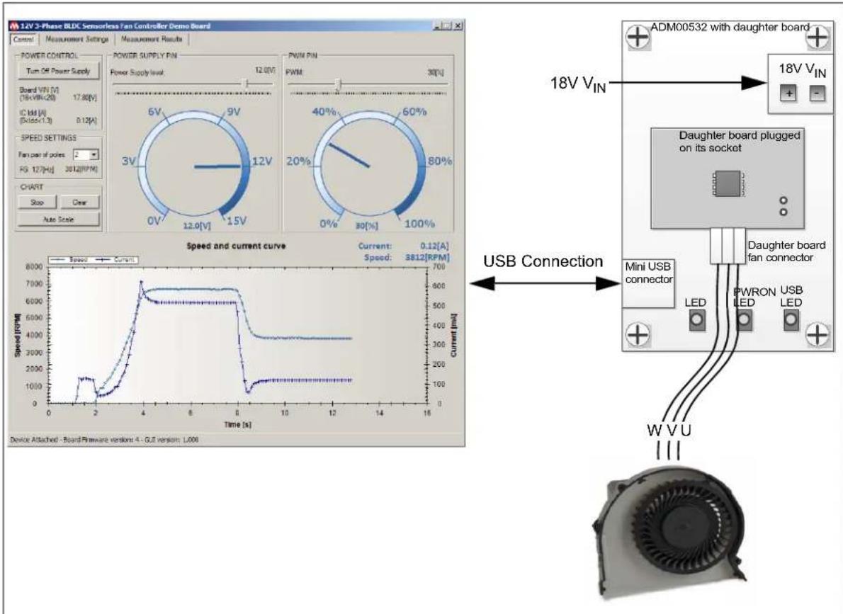
text_image
14V 3-Phase BLDG Sensorless Fan Controller Demo Board Control Measurement Settings Measurement Results POWER CONTROL Turn Off Power Supply Board VIN [V] (76+VIN=20) 17.80[V] IC IM [A] (Rdd=1.3) 0.12[A] SPEED SETTINGS Fan pin of poles: - FG 127[H] 3812[RFM] CHART Stop Clear Auto Scale POWER SUPPLY PIN Power Supply level: 12.0V 6V 9V 3V 12V 0V 15V PWM PIN PWM 30% 40% 60% 20% 80% 0% 100% Speed and current curve Current: 0.12[A] Speed: 3812[RFM] Speed [RPM] USB Connection ADMO0532 with daughter board 18V VIN 18V VIN Daughter board plugged on its socket Mini USB connector LED PWRON USB LED W V U Device Attached - Board Firmware version: 4 - GJ version: 1,000FIGURE 1-1: System Overview.

FIGURE 1-2: MCP8063 12V 3-Phase BLDC Sensorless Fan Controller Demonstration Board Kit Overview.
1.2 MCP8063 12V 3-PHASE BLDC SENSORLESS FAN CONTROLLER DEMONSTRATION BOARD HARDWARE DESCRIPTION
The MCP8063 12V 3-Phase BLDC Sensorless Fan Controller Demonstration Board contains several components:
- PIC24FJ64GB002 microcontroller for USB connection, PWM generation, FG frequency measurement, V_DD measurement, activation of other signals and component communication
- MCP1824 LDO regulator to provide 3.3V to the microcontroller
- MCP19110 buck regulator to provide power supply to the fan driver
- MCP3421 Delta-Sigma ADC for sensing the fan driver current consumption
More details on the schematic are available in Appendix A. "Schematics and Layouts".
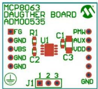
1.3 MCP8063 DAUGHTER BOARD
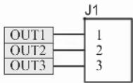
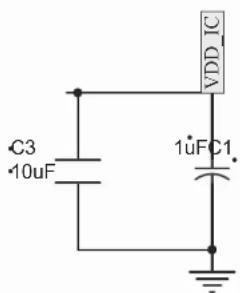
This section provides a brief description of the daughter board (ADM00535) which is included in the MCP8063 12V 3-Phase BLDC Sensorless Fan Controller Demonstration Board Kit. The MCP8063 Daughter Board has been designed to be used with a motherboard. However, it can also be used independently as a standalone board. The board overview is represented in Figure 1-3.

text_image
FG GND V_BIAS GND GND R1 C2 C1 C3 PWM Not connected V_DD V_DD V_DD GND OUT1-2-3Note 1: R1 is the FG pull-up resistor
2: C1 and C3 are the V DD decoupling capacitors.
3: C2 is the V BIAS decoupling capacitor.
FIGURE 1-3: MCP8063 Daughter Board Overview.
The daughter board also features a 3-phase BLDC motor connector that can be used to attach a fan.
More details on the schematic are available in Appendix A. "Schematics and Layouts"
1.4 WHAT THE MCP8063 12V 3-PHASE BLDC SENSORLESS FAN CONTROLLER DEMONSTRATION BOARD KIT INCLUDES
The MCP8063 12V 3-Phase BLDC Sensorless Fan Controller Demonstration Board Kit (ADM00575) includes:
- MCP8063 12V 3-Phase BLDC Sensorless Fan Controller Demonstration Board (ADM00532)
• 3 x MCP8063 Daughter Boards (ADM00535) - One mini-USB cable
- Important Information Sheet
NOTES:
Chapter 2. Installation and Operation
2.1 GETTING STARTED
The following sections describe how to use the MCP8063 12V 3-Phase BLDC Sensorless Fan Controller Demonstration Board.
2.1.1 Software Installation
Download the MCP8063 12V 3-Phase BLDC Sensorless Fan Controller Demonstration Board software installer from the Microchip website at www.microchip.com. The GUI can be downloaded from this web page as well.
Note: This application requires Microsoft ^® .NET Framework 3.5 or later.
- Unzip the archive and click on the .exe file. The MCP8063 Demo Board GUI Setup will initiate. Click Next to start the installation.
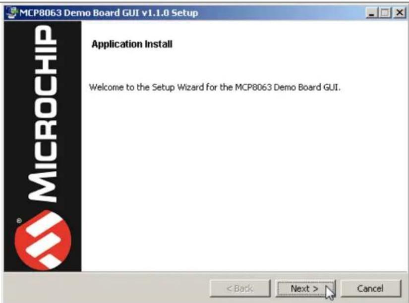
text_image
MCP8063 Demo Board GUI v1.1.0 Setup MICROCHIP Application Install Welcome to the Setup Wizard for the MCP8063 Demo Board GUI. < Back Next > CancelFIGURE 2-1: MCP8063 Demo Board GUI - Welcome Screen.
- To proceed with the installation, read the License Agreement. Accept by clicking the radio button corresponding to I accept the agreement, then click Next.

text_image
MCP8063 Demo Board GUI v1.1.0 Setup License Agreement Please read the following License Agreement. You must accept the terms of this agreement before continuing with the installation. MICROCHIP IS WILLING TO LICENSE THE ACCOMPANYING SOFTWARE AND DOCUMENTATION TO YOU ONLY ON THE CONDITION THAT YOU ACCEPT ALL OF THE FOLLOWING TERMS. TO ACCEPT THE TERMS OF THIS LICENSE, CLICK "I ACCEPT" AND PROCEED WITH THE DOWNLOAD OR INSTALL. IF YOU DO NOT ACCEPT THESE LICENSE TERMS, CLICK "I DO NOT ACCEPT," AND DO NOT DOWNLOAD OR INSTALL THIS SOFTWARE. MICROCHIP NON-EXCLUSIVE SOFTWARE LICENSE AGREEMENT FOR MCP8063 Demo Board GUI Do you accept this license? ● I accept the agreement ○ I do not accept the agreement < Back Next > CancelFIGURE 2-2: MCP8063 Demo Board GUI - License Agreement Screen.
- On the Installation Directory dialog, browse for the desired location, or click Next to install in the default location.
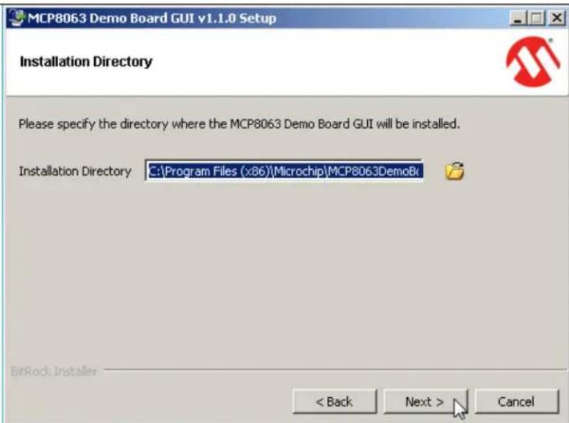
text_image
MCP8063 Demo Board GUI v1.1.0 Setup Installation Directory Please specify the directory where the MCP8063 Demo Board GUI will be installed. Installation Directory C:\Program Files (x86)\Microchip\MCP8063DemoBk BitRock Installer < Back Next > CancelFIGURE 2-3: MCP8063 Demo Board GUI - Installation Directory Screen.
- Once the path is chosen, the software is ready to install. Click Next to proceed. The installation status window appears, showing the installation progress. Click Next to proceed.

text_image
MCP8063 Demo Board GUI v1.1.0 Setup Ready to Install Setup is now ready to begin installing the MCP8063 Demo Board GUI on your computer. BitRock Installer < Back Next > CancelFIGURE 2-4: MCP8063 Demo Board GUI - Ready to Install Screen.
- Once the Install Complete screen appears, click Finish to exit the Installer.
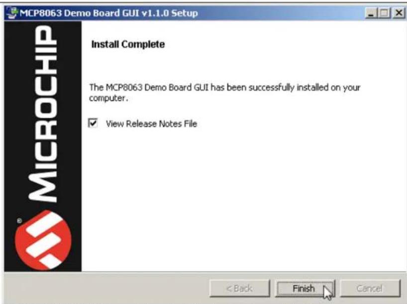
text_image
MCP8063 Demo Board GUI v1.1.0 Setup Install Complete The MCP8063 Demo Board GUI has been successfully installed on your computer. ✓ View Release Notes File < Back Finish CancelFIGURE 2-5: MCP8063 Demo Board GUI - Install Complete Screen.
- Start the software by either going to Windows Start button > All Programs > Microchip > MCP8063DemoBoardGUI or by double-clicking the software icon on the desktop.
2.1.2 Board Installation
Figure 2-6 identifies the required points for using the MCP8063 12V 3-Phase BLDC Sensorless Fan Controller Demonstration Board.

Legend:
1 = Power input connector (16V to 20V) 4 = ON, PWR (fan driver powered) and USB status LED indicators
2 = Daughter board socket 5 = Mini-USB connector
3 = Daughter board fan connector 6 = Plugged daughter board
FIGURE 2-6: Top View - Hardware Components.
To use the MCP8063 12V 3-Phase BLDC Sensorless Fan Controller Demonstration Board Kit, these steps should be followed:
- Plug in the MCP8063 Daughter Board on its socket (see Figure 2-6).
- To plug in a 3-phase BLDC sensorless fan, use the MCP8063 Daughter Board fan connector. Note that the connection can be done in normal or reverse mode. If the fan rotates in reverse mode, the connector can be flipped to rotate in normal mode.
- Start the MCP8063 12V 3-Phase BLDC Sensorless Fan Controller Demonstration Board software.
- Plug the mini-USB cable from the USB port of a computer to the MCP8063 12V 3-Phase BLDC Sensorless Fan Controller Demonstration Board connector. The LED indicating a ON state will light up.
- If required, let the computer identify the MCP8063 12V 3-Phase BLDC Sensorless Fan Controller Demonstration Board. Once the USB connection is ready, the USB LED will light up and remain on for as long as the USB connection is active.
- Restart the computer, if required.
- Connect the power supply to the V_IN test point. The V_IN value is 18V ± 10% . The power supply should be able to deliver up to 1.0A. The GUI should report the V_IN value of the board.
Note: The order of these steps is provided as an example and can be changed.
2.2 MCP8063 12V 3-PHASE BLDC SENSORLESS FAN CONTROLLER DEMONSTRATION BOARD KIT SOFTWARE DESCRIPTION
The MCP8063 12V 3-Phase BLDC Sensorless Fan Controller Demonstration Board Kit software window contains three tabs:
• Control: provides the options available for controlling and monitoring the MCP8063 12V 3-Phase BLDC Sensorless Fan Controller Demonstration Board
• Measurement Settings
• Measurement Results
2.2.1 Control Tab
Figure 2-7 shows the options and functions available for controlling and monitoring the board.
Note: All functions presented in Figure 2-7 are enabled only when the MCP8063 12V 3-Phase BLDC Sensorless Fan Controller Demonstration Board is connected to the PC via a USB connection.
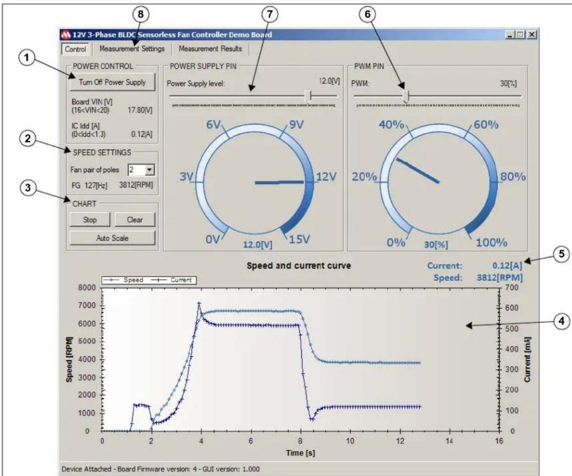
line
| Time [s] | Speed [RPM] | Current [mA] | |----------|-------------|--------------| | 0 | 0 | 0 | | 2 | ~1500 | ~500 | | 4 | ~7000 | ~600 | | 8 | ~6000 | ~500 | | 12 | ~3500 | ~350 | | 16 | ~3500 | ~350 |Legend:
1 = Power Control group box 5 = Instant current and speed measurement
2 = Speed Settings group box 6 = PWM duty cycle signal control
3 = Chart group box 7 = Fan driver power supply level control
4 = Current and speed chart display 8 = Buttons for access to other tabs
FIGURE 2-7: GUI - Control Tab.
2.2.1.1 POWER CONTROL
The Power Control group box includes the Turn On/Off Power Supply button which allows the power supply of the fan driver to be enabled/disabled.
Before enabling the fan driver power, verify that the input voltage level indicated for the board is between 16V to 20V. Running outside this range may work but stability cannot be ensured. The power supply part on the board is not able to generate a voltage level above the input voltage level.
The current is monitored and the fan driver power supply will shut down if the current goes above 2.5A.
2.2.1.2 SPEED SETTINGS
This group box allows monitoring the FG pin frequency from the fan driver in Hz. This frequency is converted to mechanical speed (Revolutions Per Minute - RPM). In order for the RPM mechanical speed to be displayed correctly, a 4P/6S fan (two pairs of poles) has to be plugged in. If the plugged motor contains a different number of poles, the value can be adapted so that the mechanical RPM is displayed correctly.
2.2.1.3 CHART
This section activates and controls the chart described in Section 2.2.1.4 "Display Chart". The chart adds 10 values per second. The three buttons have the following functions:
- Start/Stop – Allows the value acquisition to start or stop
- Clear – Removes all the values added to the chart
- Auto Scale – Allows the default scaling to be restored. In Default Scaling mode, the chart will automatically adjust the scaling to ensure the complete view of all the added values. In addition, when selecting a part of the chart with the mouse, it is possible to zoom in the selection. The mouse wheel zoom in/out is also enabled.
2.2.1.4 DISPLAY CHART
Once enabled, the chart will display the speed curve in RPM and the measured current curve in mA over time. The chart adds 10 values per second.
2.2.1.5 CURRENT AND SPEED INDICATOR
This part clearly shows the instant current consumption and the instant speed.
2.2.1.6 PWM PIN
The PWM Pin box provides a slide bar to set the PWM duty cycle on the fan driver PWM pin. The gauge corresponding to the PWN function indicates the PWM duty cycle currently applied by the MCP8063 12V 3-Phase BLDC Sensorless Fan Controller Demonstration Board.
2.2.1.7 FAN DRIVER POWER SUPPLY LEVEL CONTROL
The fan driver Power Supply Pin box features a slide bar that allows setting the desired voltage value for the fan driver. The gauge corresponding to the Power Supply function indicates the instant fan driver power supply value measured by the MCP8063 12V 3-Phase BLDC Sensorless Fan Controller Demonstration Board.
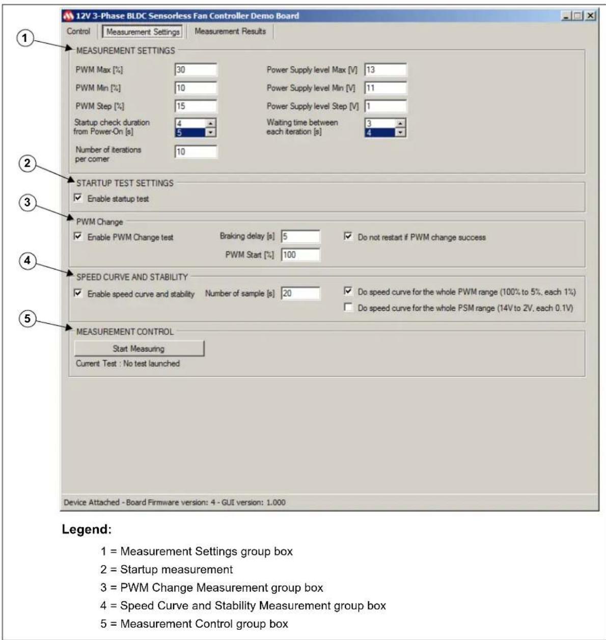
2.2.2 Measurement Settings Tab
The Measurement Settings tab features several tools for checking if the fan is correctly adapted to the fan driver by evaluating the fan behavior in different tests, several times and under different conditions.
Figure 2-8 shows the Measurement Settings tab. Next sections provide further details.
text_image
12V 3-Phase BLDC Sensorless Fan Controller Demo Board Control Measurement Settings Measurement Results 1 MEASUREMENT SETTINGS PWM Max [%] 30 Power Supply level Max [V] 13 PWM Min [%] 10 Power Supply level Min [V] 11 PWM Step [%] 15 Power Supply level Step [V] 1 Startup check duration 4 Waiting time between 3 from Power-On [s] 5 each iteration [s] 4 Number of iterations 10 2 STARTUP TEST SETTINGS ✓ Enable startup test 3 PWM Change ✓ Enable PWM Change test Braking delay [s] 5 ✓ Do not restart if PWM change success PWM Start [%] 100 4 SPEED CURVE AND STABILITY ✓ Enable speed curve and stability Number of sample [s] 20 ✓ Do speed curve for the whole PWM range (100% to 5%, each 1%) Do speed curve for the whole PSM range (14V to 2V, each 0.1V) 5 MEASUREMENT CONTROL Start Measuring Current Test : No test launched Device Attached - Board Firmware version: 4 - GUI version: 1.000 Legend: 1 = Measurement Settings group box 2 = Startup measurement 3 = PWM Change Measurement group box 4 = Speed Curve and Stability Measurement group box 5 = Measurement Control group boxFIGURE 2-8: GUI - Measurement Settings Tab.
2.2.2.1 MEASUREMENT SETTINGS
The Measurement Settings group box is used for defining the measurement corners required by the user. Once the automatic measurement starts (see Section 2.2.2.5 "Measurement Control"), all specified corners will be assessed for all selected tests. The list below details the available corner settings:
- PWM Corners Measurement – Requires the PWM Max (%), PWM Step (%) and PWM Min (%) values setting. The software will start with the maximum value entered and will decrease the PWM by the step value until it reaches the minimum entered PWM value.
- Power Supply level corners are similar to the PWM corners. A power supply level corner includes all PWM corners. This means that all PWM corners are measured for one power supply voltage level.
- Startup check duration from Power-On [s] – If the speed of the fan is measured as 0 RPM after this delay, the startup is considered a fail. The recommended value for this field is five seconds.
- Waiting time between each iteration [s] – This field specifies how many seconds are allocated for stopping the fan between two tests. This value will depend on the fan lag.
- Number of iterations per corner – This field designates the number of iterations for one corner.
2.2.2.2 STARTUP TEST SETTINGS
When the Enable startup test box is checked, the startup measurements are enabled, measuring every corner for this test. If Enable startup test is not enabled, the startup test is skipped. The other tests will be executed if they have been enabled.
2.2.2.3 PWM CHANGE
The PWM Change measurement starts with a PWM value of 100%. After the specified startup delay (entered in the Startup check duration from Power-On [s] field), the PWM changes depending on the PWM corner specified. The software will then verify if the fan is still running. If a delay value has been entered into the Braking Delay [s] field, this last check will be performed after the respective delay.
To reduce testing time, it is possible to skip the fan restart if the last PWM change has been successfully done by selecting the Do not restart if PWM change success check box.
2.2.2.4 SPEED CURVE AND STABILITY
This measuring tool requires a specified number of samples under preset conditions to check speed stability. If the Do speed curve for the whole PWM range (100% to 5%, each 1%) and/or the Do speed curve for the whole PSM range (14V to 2V, each 0.1V) check boxes are not selected, the corners previously set are measured. For this test, the number of iterations will always be one. When one of these check boxes is selected, the software will override the specified settings.
This test will report the current average, the maximum and minimum measured speed, the stability in percentage (%) and the sigma variation.
2.2.2.5 MEASUREMENT CONTROL
This group box contains a check box and a button that allows the user to control the test work flow:
- Stop Measuring – Starts and stops the required tests.
- Autosave at the end of the measurements – If checked, a measurement result file will be automatically saved when all the tests have been done. See Section 2.2.3.1 “Measurement Results” for the file location.
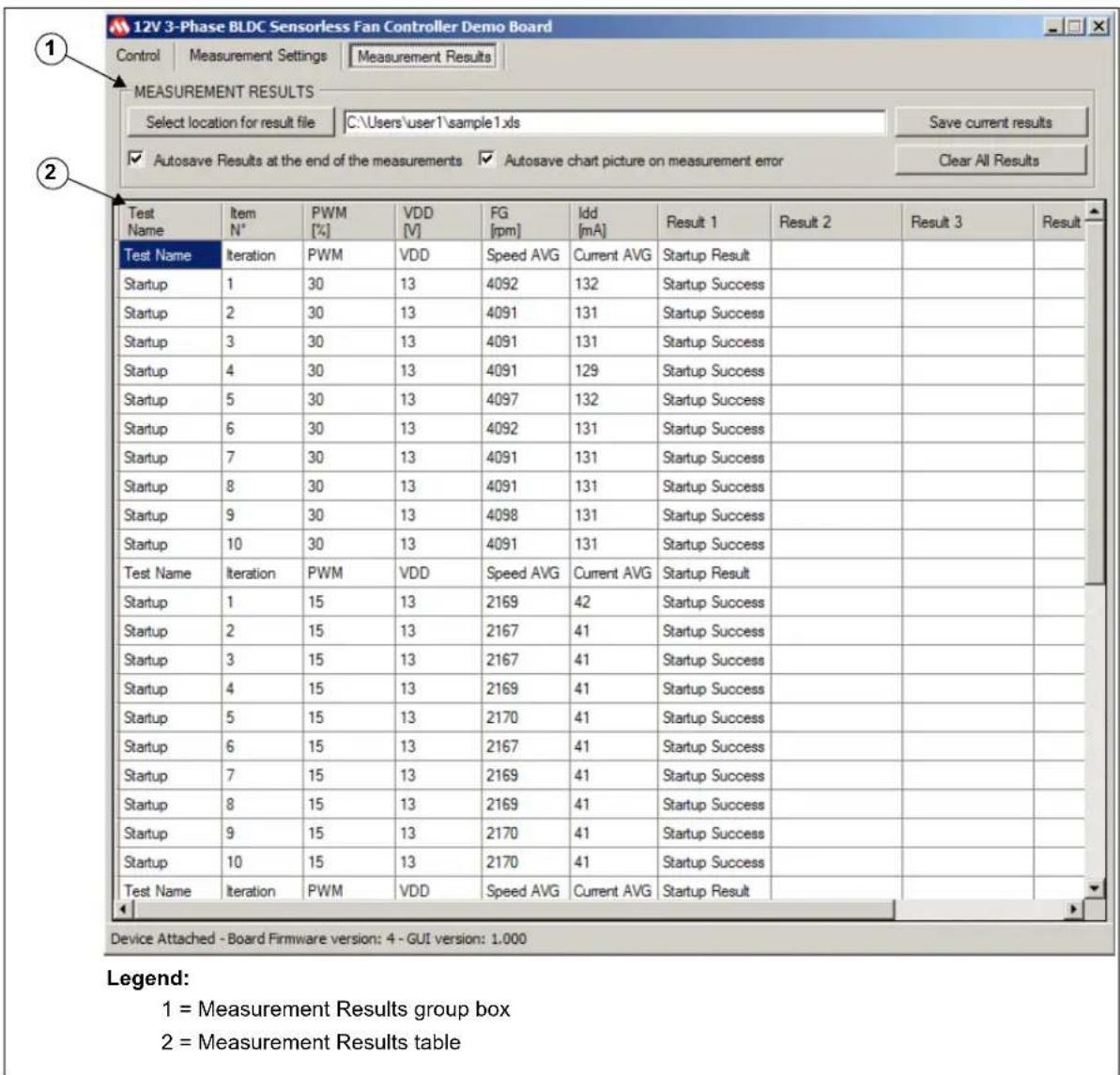
2.2.3 Measurement Results tab
The Measurement Results tab displays the test results. The user can manage from this tab where the data will be stored.
Figure 2-9 shows the Measurement Results sub-tab:
text_image
12V 3-Phase BLDC Sensorless Fan Controller Demo Board Control | Measurement Settings | Measurement Results | MEASUREMENT RESULTS Select location for result file C:\Users\user1\sample1.xls Save current results ✓ Autosave Results at the end of the measurements ✓ Autosave chart picture on measurement error Clear All Results Test Name Item N° PWM [%] VDD [V] FG [rpm] ldd [mA] Result 1 Result 2 Result 3 Result Test Name Iteration PWM VDD Speed AVG Current AVG Startup Result Startup 1 30 13 4092 132 Startup Success Startup 2 30 13 4091 131 Startup Success Startup 3 30 13 4091 131 Startup Success Startup 4 30 13 4091 129 Startup Success Startup 5 30 13 4097 132 Startup Success Startup 6 30 13 4092 131 Startup Success Startup 7 30 13 4091 131 Startup Success Startup 8 30 13 4091 131 Startup Success Startup 9 30 13 4098 131 Startup Success Startup 10 30 13 4091 131 Startup Success Test Name Iteration PWM VDD Speed AVG Current AVG Startup Result Startup 1 15 13 2169 42 Startup Success Startup 2 15 13 2167 41 Startup Success Startup 3 15 13 2167 41 Startup Success Startup 4 15 13 2169 41 Startup Success Startup 5 15 13 2170 41 Startup Success Startup 6 15 13 2167 41 Startup Success Startup 7 15 13 2169 41 Startup Success Startup 8 15 13 2169 41 Startup Success Startup 9 15 13 2170 41 Startup Success Startup 10 15 13 2170 41 Startup Success Test Name Iteration PWM VDD Speed AVG Current AVG Startup Result Device Attached - Board Firmware version: 4 - GUI version: 1.000 Legend: 1 = Measurement Results group box 2 = Measurement Results tableFIGURE 2-9: GUI - Measurement Results Tab.
2.2.3.1 MEASUREMENT RESULTS
The user can manage the results of the tests by means of the three buttons in this group:
- Select location for result file – This opens a window which allows the user to set where the test result file will be stored. The user has to make sure that the selected location has write access. In addition, Microsoft Office ^® Excel ^® 2003 or later has to be installed in order for the MCP8063 12V 3-Phase BLDC Sensorless Fan Controller Demonstration Board Software to create a Microsoft Excel file. If Microsoft Excel is not installed, it is possible to copy the data from the result table and paste it into the appropriate software.
- Save current results – This button stores the current measurements displayed in the result table in a Microsoft Excel file.
- Clear All Results – This clears the current results displayed in the result table.
2.2.3.2 RESULT TABLE
The results are shown in this table.
The first six columns are common to all tests while the others are relevant only for a particular test.
Appendix A. Schematics and Layouts
A.1 INTRODUCTION
This appendix contains the schematics and layouts for the following devices which are included in the MCP8063 12V 3-Phase BLDC Sensorless Fan Controller Demonstration Board Kit (ADM00575):
- 12V 3-Phase BLDC Sensorless Fan Controller Demonstration Board (ADM00532):
- Board – Schematic
- Board – Top Silk
- Board – Top Copper and Silk
- Board – Top Copper
- Board – Bottom Copper
- Board – Bottom Copper and Silk
- Board – Bottom Solder
• MCP8063 Daughter Board (ADM00535):
- Daughter Board - Schematic
- Daughter Board - Top Silk
- Daughter Board - Top Copper and Silk
- Daughter Board - Top Copper
- Daughter Board - Bottom Copper
- Daughter Board - Bottom Copper and Silk
- Daughter Board - Bottom Solder
A.2 BOARD - SCHEMATIC
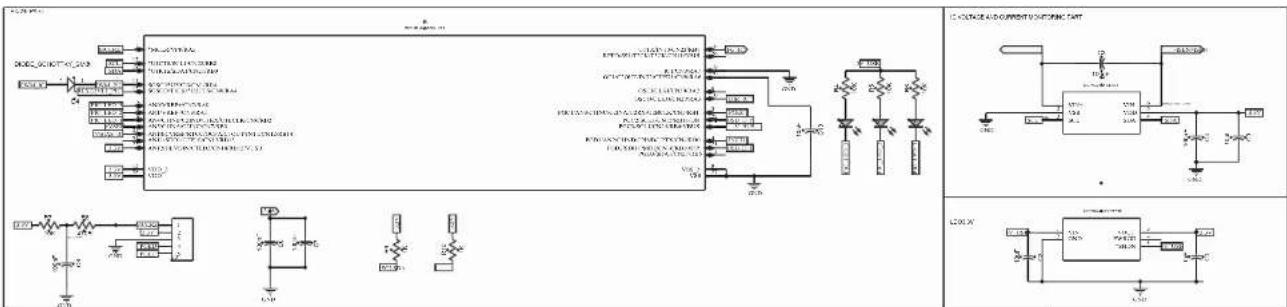
text_image
Circuit diagram and schematic of a power supply or control circuit with labeled components and connections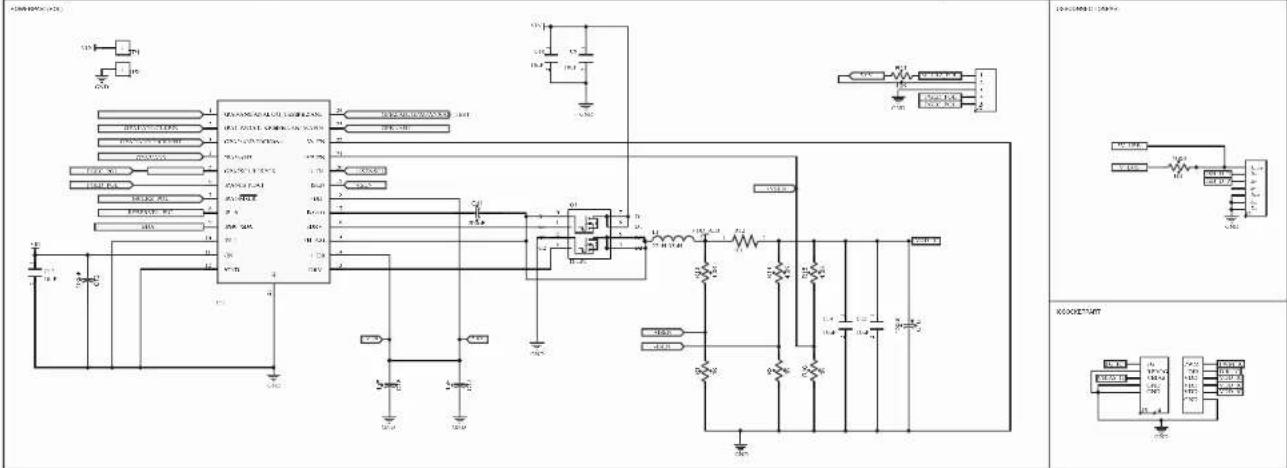
text_image
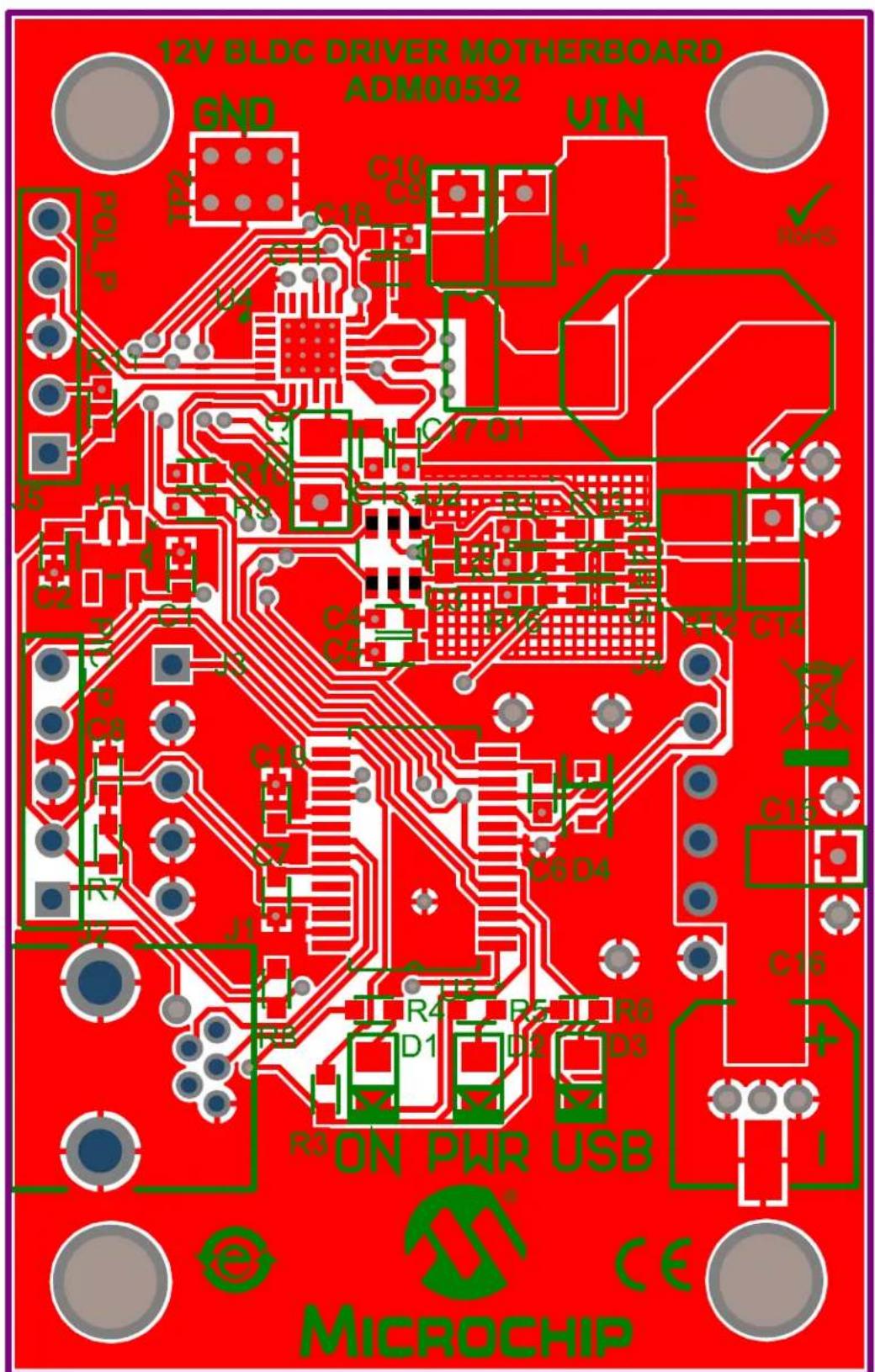
Electrical schematic diagram with labeled components and connections, including ICs, resistors, capacitors, and power supply connections.A.3 BOARD - TOP SILK

text_image
12V BLDC DRIVER MOTHERBOARD ADM00532 GND TP2 C10 C9 U1N L1 TDL Pol P R11 U4 C17 Q1 C12 C13*U2 R1 R13 R14 R16 R15 R12 C14 J5 U1 * C2 C1 C3 C4 C5 J3 PIC P C8 R7 J2 C19 C7 J1 C6 D4 U3 * R4 R5 R6 D1 D2 D3 R3 ON PWR USB C16 + I e MICROCHIP CEA.4 BOARD - TOP COPPER AND SILK
text_image
12V BLOC DRIVER MOTHERBOARD ADM00532 GND UIN TP2 C10 C9 L1 TP1 d TO1 L4 R10 C17 D1 J5 J1 C2 C1 C6 C5 R12 C12 C14 J2 C8 C19 C6 D4 J7 J1 R4 R5 R6 D1 D2 D3 R3 ON PWR USB e MICROCHIP CEA.5 BOARD - TOP COPPER

natural_image
Red printed circuit board with various traces and components, no visible text or symbolsA.6 BOARD - BOTTOM COPPER
text_image
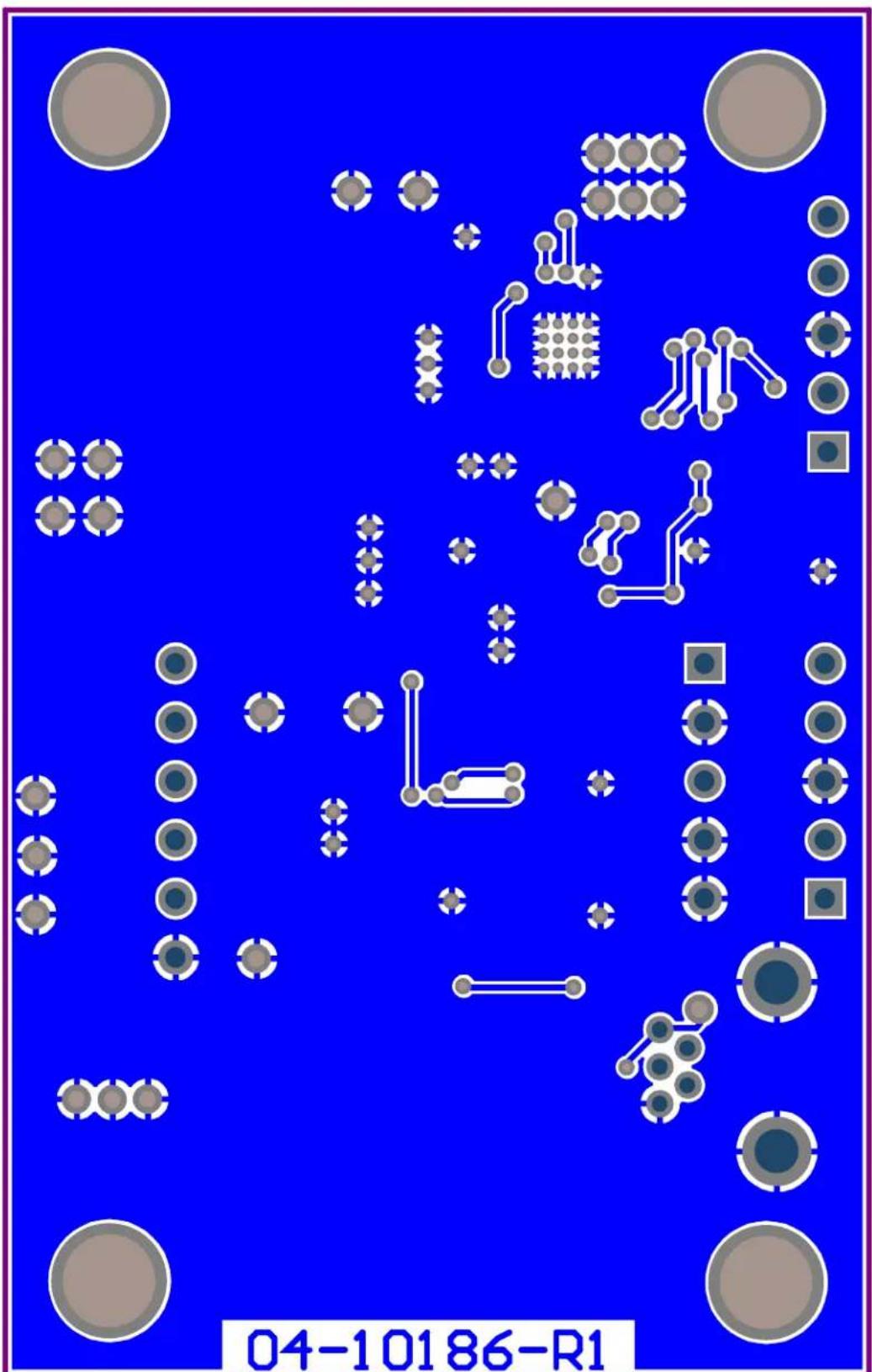
04-10186-R1A.7 BOARD - BOTTOM COPPER AND SILK

text_image
04-10186-R1A.8 BOARD - BOTTOM SOLDER
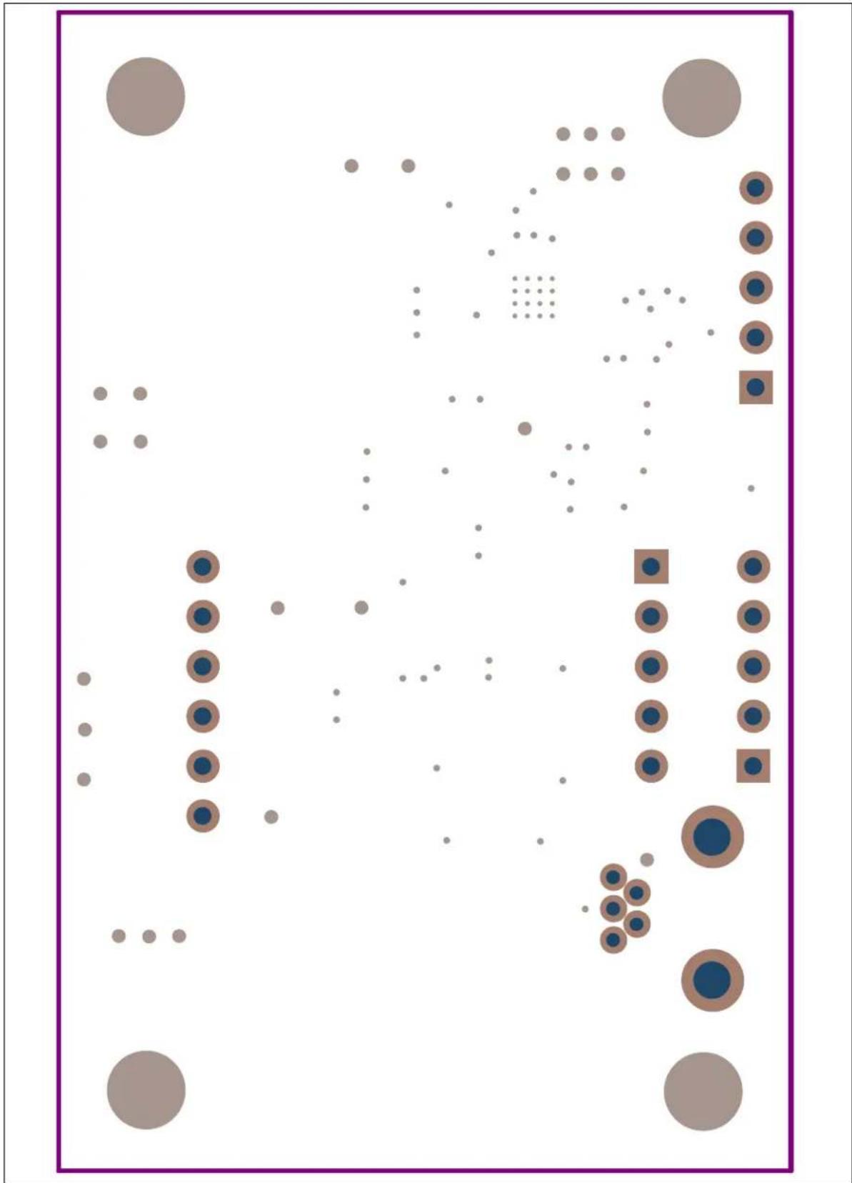
bubble
| Category | Value | | -------- | ----- | | Group 1 | 100 | | Group 2 | 80 | | Group 3 | 60 | | Group 4 | 40 | | Group 5 | 20 | | Group 6 | 10 |A.9 DAUGHTER BOARD - SCHEMATIC
text_image
-C3 -10uF VDD DC 1uFC1
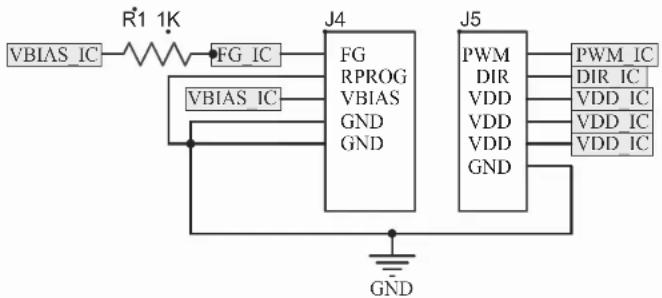
flowchart
graph TD
    A["VBIAS_IC"] --> B["R1 1K"]
    B --> C["FG_IC"]
    C --> D["J4"]
    D --> E["FG RPROG VBIAS GND"]
    D --> F["J5"]
    F --> G["PWM DIR VDD VDD GND"]
    G --> H["PWM_IC DIR VDD IC"]
    G --> I["GND"]
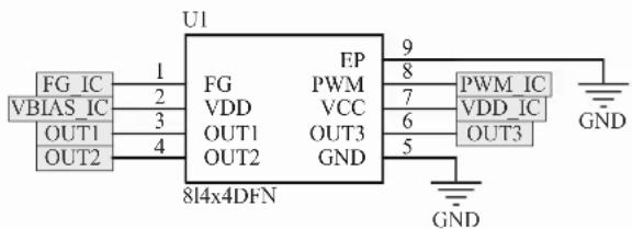
text_image
U1 FG IC 1 FG FP 9 PWM_IC VBIAS IC 2 VDD PWM 7 VDD_IC OUT1 3 OUT1 6 OUT3 OUT2 4 OUT2 GND 5 OUT3 814x4DFN GNDA.10 DAUGHTER BOARD - TOP SILK
text_image
MCP8063 DAUGHTER BOARD ADM00535 FG R1 C1 PMW GND U1 AUX VBS C2 VDD GND C3 GND J1 1 2 3 GNDA.11 DAUGHTER BOARD - TOP COPPER AND SILK

text_image
L1: P851C3 DRUGHER BOARD R000535 J1 J2 J3 J4 C1 C2 C3 C4 C5 C6 C7 C8 C9 C10 C11 C12 C13 C14 C15 C16 C17 C18 C19 C20 C21 C22 C23 C24 C25 C26 C27 C28 C29 C30 C31 C32 C33 C34 C35 C36 C37 C38 C39 C40A.12 DAUGHTER BOARD - TOP COPPER
natural_image
Pure electrical circuit lines without any symbolsA.13 DAUGHTER BOARD - BOTTOM COPPER

text_image
04-10179-R1A.14 DAUGHTER BOARD - BOTTOM COPPER AND SILK

text_image
04-10179-R1A.15 DAUGHTER BOARD - BOTTOM SOLDER

natural_image
Simple diagram with a brown square, surrounded by circular and square elements (no text or symbols)NOTES:
Appendix B. Bill of Materials (BOM)
TABLE B-1: BILL OF MATERIALS (BOM) - 12V 3-PHASE BLDC SENSORLESS FAN CONTROLLER DEMONSTRATION BOARD (ADM00532)
| Qty | Reference Description | Option Manufacturer Part Number | ||
| 3 C1 | C17, C18 Cap. | ceramic 1 μF 6.3V 10% X5R 0603 | TDK Corporation C1608X5 | R0J105K |
| 3 C2 | C5, C19 Cap. | ceramic 10 μF 6.3V 20% X5R 0603 | TDK Corporation C1608X5 | R0J106M080AB |
| 6 | C 3 , C6 – C8, C13 | Cap. ceramic 0.1 μF 25V 20% X7R 0603 | TDK Corporation C1608X7 | R1E104M080AA |
| 1 C1 | 1 Cap. ceramic 0 | 22 μF 16V 10% X7R 0603 | TDK Corporation C1608X7 | R1C224K080AC |
| 5 C9 | C10, C12, C14, C15 | Cap. ceramic 10 μF 10V Y5V 1206 | TDK Corporation C3216Y5 | V1A106Z/1.15 |
| 1 | C16 | Cap. alum. 150 μF 25V 20% SMD | Panasonic® - ECG | EEE-FTE151XAP |
| 3 | D1 – D3 | LED chip-led 633 NM red 0805 SMD | OSRAM Opto Semiconductors GmbH. | LS R976-NR-1 |
| 1 | D4 | Schottky diode 30V 0.2A SOD323 | NXP Semiconductor | 1PS76SB10,115 |
| 1 J1 | Conn. USB recept. 5 POS rt. angle Molex ® | 548190519 | ||
| 2 J2 | J5 Conn. header 5 POS 0.050" T/H gold | Samtec, Inc. | TMS-105-02-G-S | |
| 1 J3 | Conn. recept. 5 POS 0.100 vert. gold | TE Connectivity, Ltd. | 5-534237-3 | |
| 1 J4 | Conn. recept. 6 POS 0.100 vert. gold | TE Connectivity, Ltd. | 534237-4 | |
| 1 L1 | Inductor power 22 μH 30% shield SMD | Bourns®, Inc. SRU1048-2 | 20Y | |
| PCB | Printed Circuit Board – MCP8063 12V 3-Phase BLDC Sensorless Fan Controller Demonstration Board | — | 104-00532 | |
| 1 Q1 | MOSFET N-Channel dual 30V 8-SOIC | Vishay Siliconix | SI4330DY-T1-E3 | |
| 5 R1 | R2, R9, R10, R16 | Res. 1.00 kΩ 1/10W 1% 0603 | TE Connectivity, Ltd. | 1622866-1 |
| 1 | R3 | Res. 100 kΩ 1/10W 1% 0603 | TE Connectivity, Ltd. | 1622827-1 |
| 5 | R4 – R7, R11 | Res. 10.0 kΩ 1/10W 1% 0603 | TE Connectivity, Ltd. | 1622829-1 |
| 3 | R13 – R15 | Res. 4.02 kΩ 1/10W 1% 0603 SMD | Panasonic - ECG | ERJ-3EKF4021V |
| 1 | R8 | Res. 470Ω 1/10W 1% 0603 SMD | Panasonic - ECG | ERJ-3EKF4700V |
| 1 | R12 | Res. 0.1Ω 1/3W 1% 1210 SMD | Panasonic - ECG | ERJ-L14KF10CU |
| 2 TP | 1, TP2 PC test point mini SMD Keystone Electronics Corp. | 5019 | ||
| Qty | Reference Description | Manufacturer Part Number | ||
| 1 U1 | IC reg. LDO 3.3 | V 0.3A 5-leadSOT-23 | Microchip Technology Inc. | MCP1824T-3302E/OT |
| 1 U2 | IC ADC 18 bit 3. | 75 SPS 1 ch. 6-leadSOT-23 | Microchip Technology Inc. | MCP3421A1T-E/CH |
| 1 U3 | IC MCU 16 bit 6 | 4 KB Flash 28-leadSSOP | Microchip Technology Inc. | PIC24FJ64GB002-1/SS |
| 1 U4 | IC reg. controller | Buck PWM 24-leadQFN | Microchip Technology Inc. | MCP19110-E/MJ-ND |
Note 1: The components listed in this Bill of Materials are representative of the PCB assembly. The released BOM used in manufacturing uses all RoHS-compliant components.
TABLE B-2: BILL OF MATERIALS (BOM) - MCP8063 DAUGHTER BOARD (ADM00535)
| Qty | Reference Description | Option Manufacturer Part Number | ||
| 2 C1, C2 | Cap. ceramic 1 | UF 16V 10% X7R0603 | AVX Corporation | 0603YC105KAT2A |
| 1 C3 | Cap. ceramic 10UF | 16V 10% X5R1206 | AVX Corporation | 1206YD106KAT2A |
| 1 | R1 | Res. 10.0K OHM 1/16W 1% 0603 | TE Connectivity, Ltd. | 5-1879337-9 |
| 1 J1 | Conn. | header 3POS .100 R/A tin Molex® | 22288030 | |
| 1 | J2 | 5x1 header 100" SR straight | FCI | 68000-105HLF |
| 1 | J3 | Conn. header 6POS 100 STR 30AU | FCI | 68000-106HLF |
| 1 U1 MCP8063 | Microchip Technology Inc. MCP8063-E/MD | |||
Note 1: The components listed in this Bill of Materials are representative of the PCB assembly. The released BOM used in manufacturing uses all RoHS-compliant components.
NOTES:
Worldwide Sales and Service
AMERICAS
Corporate Office
2355 West Chandler Blvd.
Chandler, AZ 85224-6199
Tel: 480-792-7200
Fax: 480-792-7277
Technical Support:
http://www.microchip.com/
support
Web Address:
www.microchip.com
Atlanta
Duluth, GA
Tel: 678-957-9614
Fax: 678-957-1455
Austin, TX
Tel: 512-257-3370
Boston
Westborough, MA
Tel: 774-760-0087
Fax: 774-760-0088
Chicago
Itasca, IL
Tel: 630-285-0071
Fax: 630-285-0075
Cleveland
Independence, OH
Tel: 216-447-0464
Fax: 216-447-0643
Dallas
Addison, TX
Tel: 972-818-7423
Fax: 972-818-2924
Detroit
Novi, M
Tel: 248-848-4000
Houston, TX
Tel: 281-894-5983
Indiana
Noblesville, IN
Tel: 317-773-8323
Fax: 317-773-5453
Los Angeles
Mission Viejo, CA
Tel: 949-462-9523
Fax: 949-462-9608
New York, NY
Tel: 631-435-6000
San Jose, CA
Tel: 408-735-9110
Canada - Toronto
Tel: 905-673-0699
Fax: 905-673-6509
ASIA/PACIFIC
Asia Pacific Office
Suites 3707-14, 37th Floor
Tower 6, The Gateway
Harbour City, Kowloon
Hong Kong
Tel: 852-2943-5100
Fax: 852-2401-3431
Australia - Sydney
Tel: 61-2-9868-6733
Fax: 61-2-9868-6755
China - Beijing
Tel: 86-10-8569-7000
Fax: 86-10-8528-2104
China - Chengdu
Tel: 86-28-8665-5511
Fax: 86-28-8665-7889
China - Chongqing
Tel: 86-23-8980-9588
Fax: 86-23-8980-9500
China - Dongguan
Tel: 86-769-8702-9880
China - Hangzhou
Tel: 86-571-8792-8115
Fax: 86-571-8792-8116
China - Hong Kong SAR
Tel: 852-2943-5100
Fax: 852-2401-3431
China - Nanjing
Tel: 86-25-8473-2460
Fax: 86-25-8473-2470
China - Qingdao
Tel: 86-532-8502-7355
Fax: 86-532-8502-7205
China - Shanghai
Tel: 86-21-5407-5533
Fax: 86-21-5407-5066
China - Shenyang
Tel: 86-24-2334-2829
Fax: 86-24-2334-2393
China - Shenzhen
Tel: 86-755-8864-2200
Fax: 86-755-8203-1760
China - Wuhan
Tel: 86-27-5980-5300
Fax: 86-27-5980-5118
China - Xian
Tel: 86-29-8833-7252
Fax: 86-29-8833-7256
ASIA/PACIFIC
China - Xiamen
Tel: 86-592-2388138
Fax: 86-592-2388130
China - Zhuhai
Tel: 86-756-3210040
Fax: 86-756-3210049
India - Bangalore
Tel: 91-80-3090-4444
Fax: 91-80-3090-4123
India - New Delhi
Tel: 91-11-4160-8631
Fax: 91-11-4160-8632
India - Pune
Tel: 91-20-3019-1500
Japan - Osaka
Tel: 81-6-6152-7160
Fax: 81-6-6152-9310
Japan - Tokyo
Tel: 81-3-6880-3770
Fax: 81-3-6880-3771
Korea - Daegu
Tel: 82-53-744-4301
Fax: 82-53-744-4302
Korea - Seoul
Tel: 82-2-554-7200
Fax: 82-2-558-5932 or
82-2-558-5934
Malaysia - Kuala Lumpur
Tel: 60-3-6201-9857
Fax: 60-3-6201-9859
Malaysia - Penang
Tel: 60-4-227-8870
Fax: 60-4-227-4068
Philippines - Manila
Tel: 63-2-634-9065
Fax: 63-2-634-9069
Singapore
Tel: 65-6334-8870
Fax: 65-6334-8850
Taiwan - Hsin Chu
Tel: 886-3-5778-366
Fax: 886-3-5770-955
Taiwan - Kaohsiung
Tel: 886-7-213-7828
Taiwan - Taipei
Tel: 886-2-2508-8600
Fax: 886-2-2508-0102
Thailand - Bangkok
Tel: 66-2-694-1351
Fax: 66-2-694-1350
EUROPE
Austria - Wels
Tel: 43-7242-2244-39
Fax: 43-7242-2244-393
Denmark - Copenhagen
Tel: 45-4450-2828
Fax: 45-4485-2829
France - Paris
Tel: 33-1-69-53-63-20
Fax: 33-1-69-30-90-79
Germany - Dusseldorf
Tel: 49-2129-3766400
Germany - Munich
Tel: 49-89-627-144-0
Fax: 49-89-627-144-44
Germany - Pforzheim
Tel: 49-7231-424750
Italy - Milan
Tel: 39-0331-742611
Fax: 39-0331-466781
Italy - Venice
Tel: 39-049-7625286
Netherlands - Drunen
Tel: 31-416-690399
Fax: 31-416-690340
Poland - Warsaw
Tel: 48-22-3325737
Spain - Madrid
Tel: 34-91-708-08-90
Fax: 34-91-708-08-91
Sweden - Stockholm
Tel: 46-8-5090-4654
UK - Wokingham
Tel: 44-118-921-5800
Fax: 44-118-921-5820
01/27/15