BR500ST - Range hood Schweigen - Free user manual and instructions
Find the device manual for free BR500ST Schweigen in PDF.

User questions about BR500ST Schweigen
0 question about this device. Answer the ones you know or ask your own.
Ask a new question about this device
Download the instructions for your Range hood in PDF format for free! Find your manual BR500ST - Schweigen and take your electronic device back in hand. On this page are published all the documents necessary for the use of your device. BR500ST by Schweigen.
USER MANUAL BR500ST Schweigen
INSTALLATION GUIDE BR500ST / BR522ST BRW600ST / BRW622ST BRB700ST / BRB722ST
schweigen
Welcome
Thank you for purchasing your new Schweigen Isodrive system.
To get the maximum output from this unit, please read through this guide before use and installation.
This guide contains important information on the correct use and maintenance of the unit, as well as important safety notes. This will ensure your personal safety and the lasting value of your Isodrive system.
Please always retain your proof of purchase to aid in any warranty queries.
This appliance and its packaging are produced by processes that minimise waste and respect the environment.
Please help us to continue this effort to protect the environment by using the appliance efficiently and dispose of the packaging in a responsible manner.
- Welcome 2
2. Your Safety
Before Installation 4
Electrical Cord 4
Motor Features 5
General Notes on Installation and Use 5
Recommended Installation Distance 5
Minimum Mounting Height 6
Avoidance of Back Flow 6
Safety of Children 6
Replacement of Supply Cord 6
Why Flexi-duct 6
3. Description
Isodrive Motor 7
4. Installation
Roof Installation 9
Wall Installation 10
Flat Roof Installation 12
Through Wall Installation for Isodrive 900 13
Fan Unit Shutter Assembly for Isodrive 900 (Optional) ____ 14
Twin 200mm Outlet Installation Example ____ 15
5. Measurements
Measurements for Isodrive 900 16
6. Flexible Duct
Shallow Roof Space 18
Important Note 18
Securing Flexible Duct 19
7. Parts List
Parts List for Isodrive 900 20
8. Maintenance
Roof Restoration or Cleaning 22
- Warranty/Disclaimer 23
10.Vent Measurements 24
2. Your Safety

natural_image
Yellow triangular warning sign with black exclamation mark (no text or symbols beyond the mark)RECEIVING YOUR APPLIANCE
Please read this section thoroughly before attempting to operate the appliance. Inspect your product upon receipt. Any damage or defects MUST be reported within 48 hours, or no claim will be recognised.
DO NOT INSTALL THIS APPLIANCE IF YOU FIND IT DAMAGED.
If this product is installed damaged, the supplier, nor the retailer, will be responsible for the costs associated with the repair, replacement, removal or re-installation of the appliances.
This appliance is not intended for use by person/s (including children) with reduced physical, sensory or mental capabilities, or lack of experience and/or knowledge. Unless the person has been given supervision or instruction concerning the use of the appliance by a person responsible for their safety. Children should be supervised to ensure that they do not play with the appliance, it is not a toy.
Do not install Isodrive motor to a non-Schweigen and/or non-silent rangehood. If you fail to do so, your warranty will be voided.
The manufacturer declines all responsibility in case of failure to adopt proper safety measures.
Ensure that the location in which this appliance is installed, has good and permanent ventilation.
Please consult local laws and regulations and install in accordance.
Use an electrical connector with earth that is correct for your location.
Check that the voltage in your area corresponds to the appliance as indicated on the rating label.
Before Installation
We recommend this appliance to be installed or repaired by a qualified Schweigen Home Appliances technician.
Please see our website www.schweigen.com.au for recommended installers.
It is dangerous to modify any part of this appliance. Modification of any kind, will immediately void the warranty.
Electrical Cord
Ensure the supply cord is not exposed to heat, chemicals or sharp objects. If the supply cord is damaged, it must be replaced by the manufacturer, service agent or a similarly qualified person in order to avoid a hazard. The power supply cord connection MUST BE installed in such a way that access is easy in case of emergency.
This guide is for the installation of the Isodrive motor system after the canopy/rangehood or bathroom extraction grill has been mounted on the wall or ceiling. (Refer to canopy/rangehood or bathroom extraction unit installation manual).
NOTE: All PVC pipe and flexi ducting measurements are referring to inside measurements, unless otherwise mentioned.
Motor Features
- Roof and wall mounting with IPX4 degree of weather protection.
• Super quiet, long vane, backward curved centrifugal fan. - Airflow is dependant on installation and the ducting used. Using single 200mm flex duct, you should attain up to 900m^3/hr and depending on the ducting installation. The use of a smaller than 150mm (ISD) pipe would result in a loss of airflow.
- Simple installation: mounts onto a 150mm PVC pipe for ultimate strength and allows for easy Dektite roof sealing.
- Industrial quality motor and fan made in Germany and rated at 40,000 hours.
- Motor is a high efficiency PSC type and rated at 57W.
- WARRANTY 5 YEARS return to manufacturer. Covers faulty manufacturing or components. It does not cover normal wear and tear.
General Notes on Installation and Use
This fan unit is designed to be installed using 150mm (ISD) PVC pipe as the initial connection duct to the fan module, and is supplied with a 150mm (ISD) PVC pipe to 200mm (ISD) flexible duct bell-mouth adaptor.
This fan is suitable for connection to multiple duct runs with a minimum inlet area of 22,000mm² and length up to 10 metres maximum (check with supplier if longer duct length required). Where possible flexible ducting must be extended sufficiently to present a smooth air passage with bends of at least the radii of twice the diameter of the duct.
WARNING: The rangehood must not be ducted into a wall cavity or a ceiling space, where a build up of grease can occur and become a potential fire risk. This will void warranty.
NOTE: Fan module and dual foil flexi-duct are acoustically matched. Use of semi-rigid or rigid ducting will result in increased noise and may void warranty. See installation instruction notes 'Why flexi-duct'.
Recommended Installation Distance
Isodrive 900 motor, recommended 4 to 5 metres of flexi ducting.
NOTE: Although less than 4 to 5 metres will increase extraction power this will result in higher noise level. Maximum duct length 10 metres. Check with supplier if longer duct length is required. Do not reduce the duct size at any time and avoid sharp bends.
2. Your Safety
Minimum Mounting Height
This fan unit is intended for mounting at a minimum height of 2.1 metres (measured to the lower part of the fan impeller) above a floor or the ground.
Avoidance of Back Flow
Care should be taken to avoid the back flow of gases into the room from the open flue of gas or other open fire appliances.
Safety of Children
This fan is not intended for use by young children or infirm persons without supervision.
Replacement of supply cord
If the supply cord is damaged, it must be replaced by a service agent or suitably qualified person in order to avoid a hazard.
Why Flexi-duct
Some internet sites strongly recommend the use of rigid ducting over fully flexible ducting. This may well be the case with conventional rangehoods with internal motor rangehood but not with external motor rangehood.
Schweigen's unique Isodrive system works in the opposite way to conventional rangehoods, pulling air through the hood and acoustically matched ducting, producing almost silent high volume flow. The use of a complete rigid or semi-rigid ducting system will allow an organ piping effect to occur; like a didgeridoo where a noise is produced at one end of a hollow rigid pipe and the noise is amplified out the other.
The Isodrive system places the noise outside the house and it needs to be kept there.
WARNING: Installation without the use of at least the minimum recommended length of acoustically matched flexi-ducting in the system will void performance expectations. Any installation problem must be reported to Schweigen. Call outs relating to incorrect installation will result in a service fee direct to the customer. Schweigen takes no responsibility for problems caused by faulty installation, this may void warranty. A preferred installer list can be obtained from Schweigen website www.schweigen.com.au or by calling 1300 881 693.
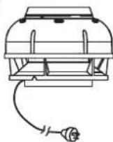
Isodrive Motor
Included in the box:
- Isodrive 900 motor (280W x 200H mm approx.) Approx. 3 metre, 10amp cable and standard male plug
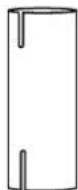
- Fire resistant 150mm (160mm OD ^1 ) PVC riser pipe Note: Cable cut-out at the bottom end only
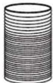
- Flexible ducting Approx. 4 metres, 200mm (210mm OD ^1 ) diameter
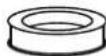
- Bell-mouth adopter ring 200mm duct to 150mm riser
- Back draft shutter (200mm BDSS Build Ass)
Not included in the box:
- Roof seal kit / Dektite
- Support straps for poly pipe which connects to the roof truss
- Aluminium Foil tape
• Wall Cover Plate (wall mount only) - Zip ties
①
②
③
④
⑤
4. Installation
text_image
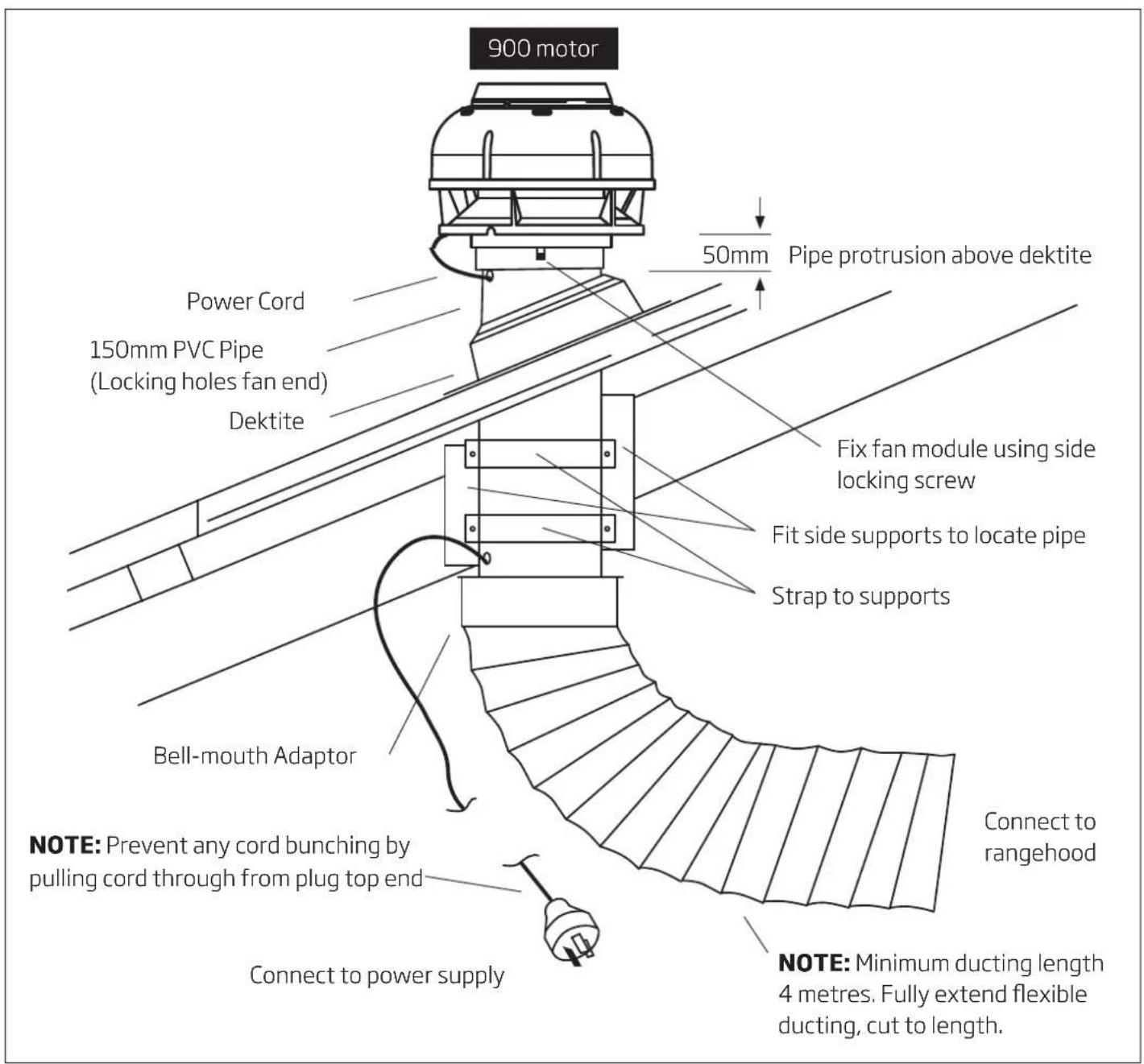
900 motor 50mm Pipe protrusion above dektite Power Cord 150mm PVC Pipe (Locking holes fan end) Dektite Fix fan module using side locking screw Fit side supports to locate pipe Strap to supports Bell-mouth Adaptor NOTE: Prevent any cord bunching by pulling cord through from plug top end Connect to power supply Connect to rangehood NOTE: Minimum ducting length 4 metres. Fully extend flexible ducting, cut to length.Figure 1 Roof Mount Option
Roof Installation
Recommended duct length: minimum 4 metres.
Mount 150mm (ISD) rigid PVC pipe securely to beams, trusses or other appropriate structures: refer figure 1. The pipe should be mounted vertically with the roof penetration being sealed using a Dektite or other appropriate sealing membrane or device.
Ensure that the PVC pipe protrudes at least 50mm past the top of the Dektite, checking that the fan assembly clears the roof cladding at upper edge, refer figure 1.
Pass power cord and plug through mounting flange and pipe, then out the slotted PVC pipe for connection to the female plug coming from the canopy/rangehood. Refer to figure 4.
Do not insert plug into socket outlet or switch on until installation has been completed. Fit fan module to pipe and fix in position using side locking screw.
Certain external installation configurations may cause audible levels of noise to be heard due to the air being expelled from the motor. To minimize external noise disturbance you can use between 6 to 10 metres of flexi duct to place the Isodrive motor in an appropriate position.
Please be aware that the 900 motor is capable of expelling air at 900m^3/hr .
For more information on environmental noise limit and conditions please contact your local Council. We have a list of recommended installers available on the Schweigen website.
4. Installation
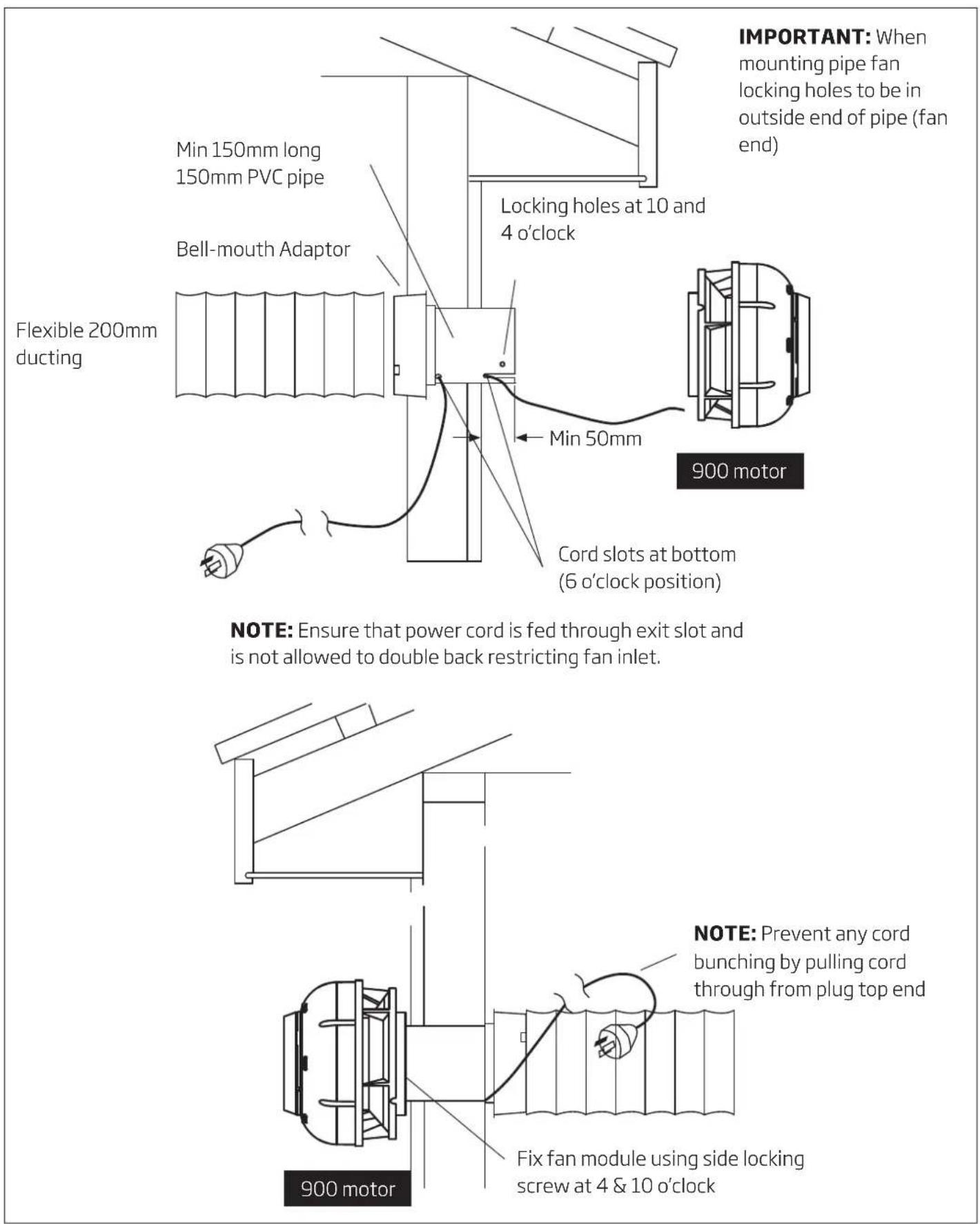
Wall Installation
This type of installation is similar to roof mounting, ensuring that the pipe extends at least 50mm past the wall surface refer figure 2. If the pipe length is shortened, reproduce the power cord exit slot on the inside of the wall.
NOTE: By decreasing the length of the flexi duct from which specified (refer to installation instructions) there will be an increase in airflow and noise levels as a result. This increase in airflow can cause movement of air to be heard through the system and inhibit the system to run silently.

text_image
Optional Mounting Flange (P40113MF*) From outside face of flange to end of pipe (or wall if mounting flange not used) 50 Fill gap between pipe and wall or fit second wall mount flange if required Wall 150mm PVC Stormwater Pipe Locking screws Locking holes at 4 and 10 o'clock 900 motor Wall Optional Fitment Pipe Seal with silicone or urethane Power cord to 240V supply 50 Locking screws to be fully tightened engaging in holes *Optional wall mounting flange (P40113MF) is available from Schweigen, please contact 1300 881 693.Figure 2 Wall Installation

IMPORANT
For more flexible ducting instructions, refer page 22.
text_image
Flexible 200mm ducting Min 150mm long 150mm PVC pipe Bell-mouth Adaptor 900 motor Cord slots at bottom (6 o'clock position) NOTE: Ensure that power cord is fed through exit slot and is not allowed to double back restricting fan inlet. 900 motor IMPORTANT: When mounting pipe fan locking holes to be in outside end of pipe (fan end) Locking holes at 10 and 4 o'clock Min 50mmFigure 3 Wall Mount Option
4. Installation
Flat Roof Installation
Flat roof mounting using optional mounting flange*.

text_image
900 motor Engage locking screws in holes Seal 3 holes in stepped surface Seal between mounting flange and cover Up-stand and capping Power supply cord passing through pipe slots Optional mounting flange P40113MF* Seal top edge of flange Protrusion of pipe above mounting flange Bond flange to pipe using silicone, urethane or type 'N' PVC solvent cement Roof Cladding NOTE: Cut 150mm PVC storm water pipe to length and reslot ducting end. Ensure that fan end locking holes remain 200mm Flexible Ducting *Optional wall mounting flange (P40113MF) is available from Schweigen, please contact 1300 881 693Figure 4
Installation Through Wall for Isodrive 900

text_image
Fan Unit Shutter Assembly (200mm BDSS BUILD ASS) Ensure that power cable passes through the cover plate notched recess and is clear of cut edges Optional wall cover plate with notch at bottom P1108* Minimum pipe protrusion from wall surface Wall 47mm Wall cover plate (optional part) Power cord Slot in pipe at bottom (6 O'Clock)*Optional parts are available from Schweigen, please contact 1300 881 693
Figure 5
4. Installation
Fan Unit Shutter Assembly for Isodrive 900 (Optional)
- Assemble by fitting shutter assembly into fan inlet shroud moulding, ensuring that attaching screws align with holes. Alignment can be checked visually by folding in shutter flaps.
- Fully tighten both screws and re-check fitment into holes.
- Fit assembly to duct pipe as per installation instructions supplied.

text_image
Attaching screws Attaching hole Inlet shroud moulding Shutter AssemblyNOTE: With through wall installations flap shaft will be close to vertical
Figure 6
BR522ST, BRW622ST, BRB722ST Duel Vent System or optional DVK500ST Installation

text_image
For dual installation, bathroom, toilet or laundry, adjust inlet grilles to balance air flow as required. The strongest extraction should be at the shower, please adjust damper accordingly. Bell-mouth Adaptor 2m of ducting Optional Y-branch To main power/switch Additional dual vent kit, Y-branch, 3 metre length flexi ducting and inlet grille with adjustable damper 2m of ducting Cut 232mm dia hole for grille fitmentFigure 2 Ventilation Option for Dual Vent

IMPORTANT
- Do not reduce the ducting size. 200mm must be used. Reducing the ducting will reduce extraction
• No sharp bends in the ducting - Do not kink the ducting
- keep the amount of bends in the ducting to 2 or 3
- Do not use semi-rigid or solid ducting
5. Measurements
Measurements for Isodrive 900 (Not to Scale)
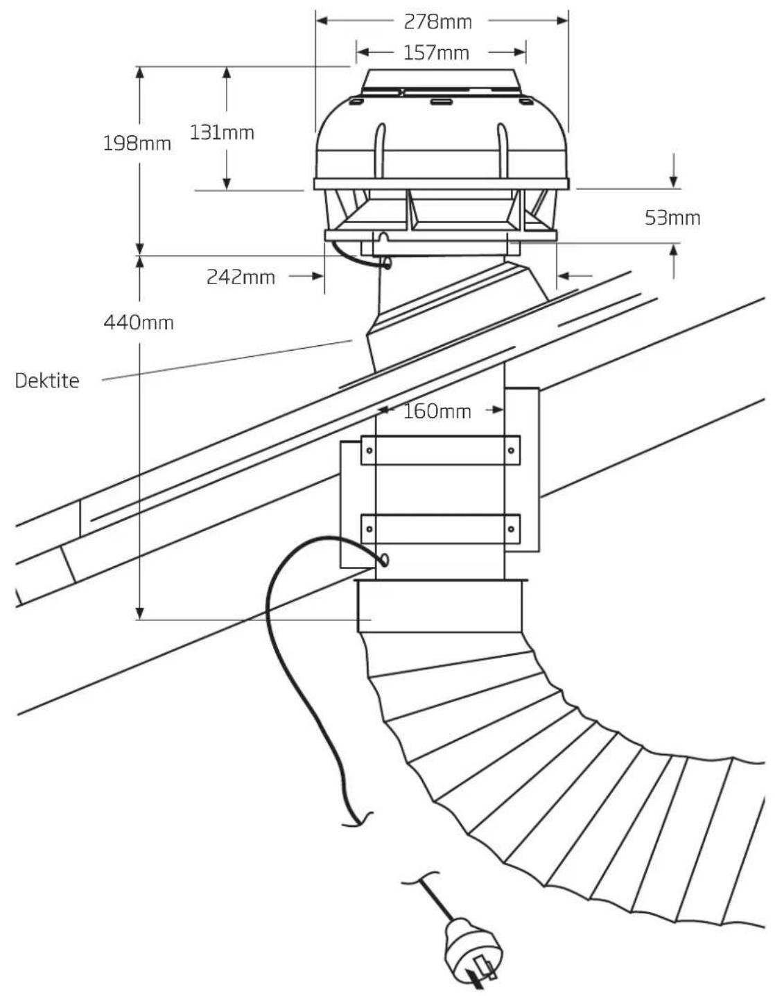
text_image
278mm 157mm 198mm 131mm 242mm 53mm 440mm Dektite 160mmFlexible Ducting
Flexible ducting must be fully extended and cut to the required length upon installation. Maximum fan performance will not be achieved unless the ducting is fully extended. Failure to fully extend ducting results in a smaller air passage and lower airflows. Incorrect installation may reduce airflow or increase noise levels. Call outs relating to incorrect installation will result in a service fee directed to the customer. Schweigen will take no responsibility for problems caused by faulty installation. A list of preferred Schweigen installers can be obtained from the Schweigen website www.schweigen.com.au.
6. Flexible Duct
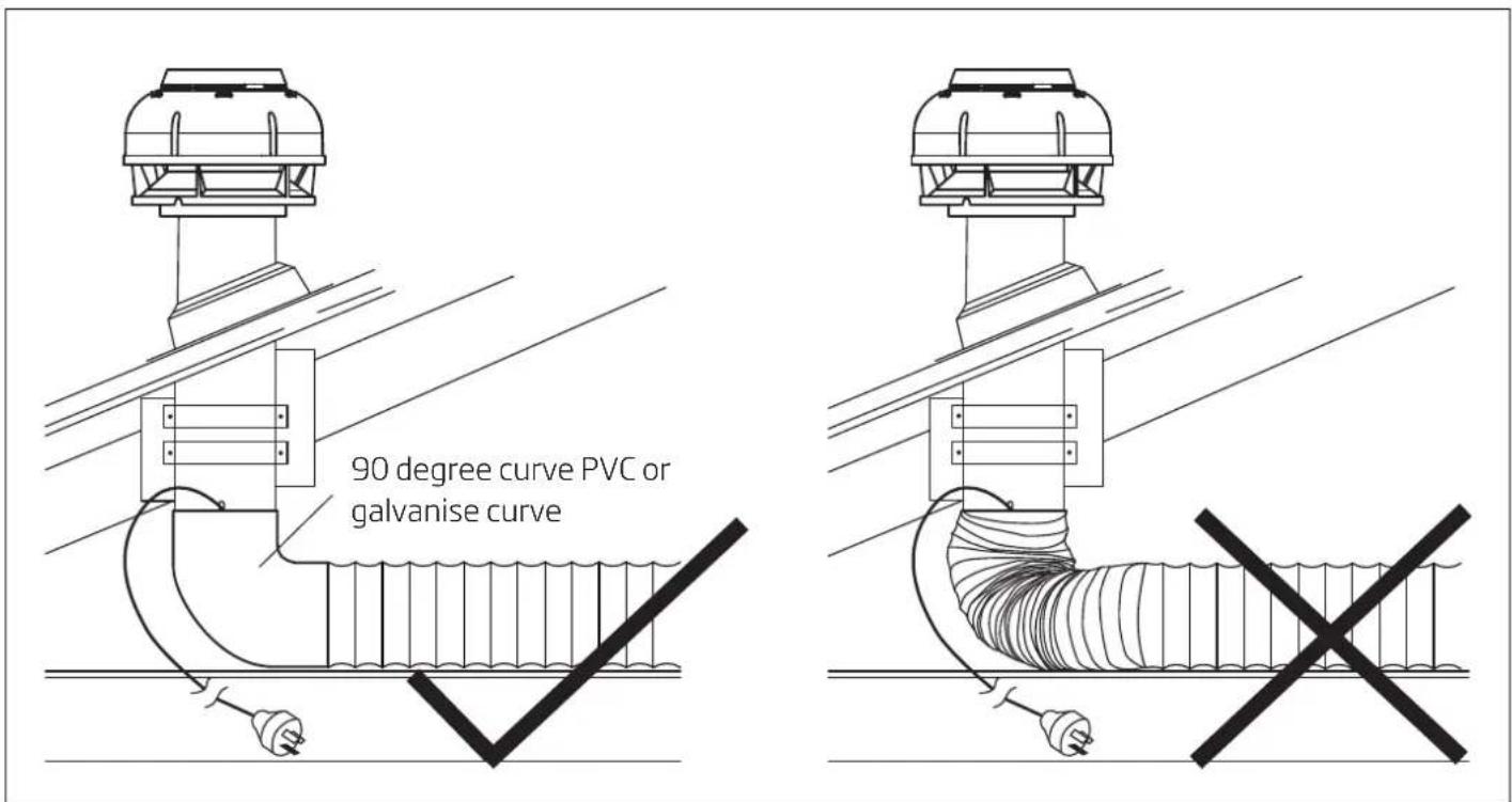
Shallow Roof Space
In shallow roof spaces, do not crush or kink flexible ducting, as it will reduce air flow severely. 90 degree curve made of PVC or galvanise can be used as a substitute for the bend, refer to figure 12.
text_image
90 degree curve PVC or galvanise curveFigure 12
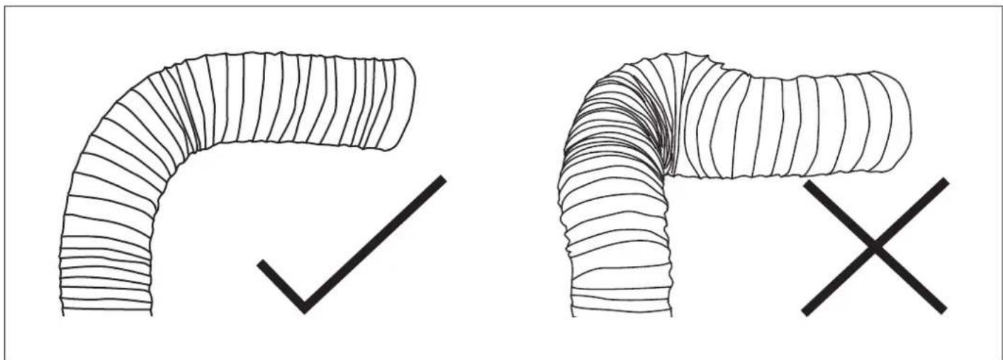
Important Note
Please do not crush or kink flexible ducting, as it will reduce air flow and may cause noise to occur through the system. Ducting needs to be kept taut at all times.
text_image
Hand-drawn diagrams showing a curved pipe with a checkmark and an X symbol, likely illustrating a verification or modification process.Figure 13
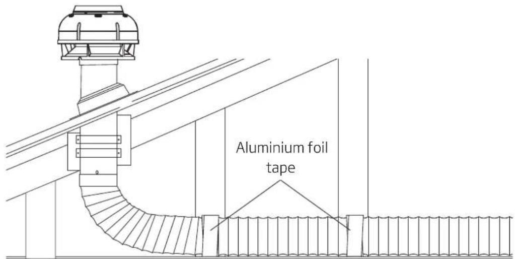
Securing Flexible Duct
Flexible duct must be installed with supports at maximum intervals of 1.5 metres. Flexible ductwork can be supported by using gaffer or electrical tape. Provided that it does not restrict the internal diameter of the ducting. Ducting installed looped over hanging beams should be installed in such a manner as to ensure the changes of direction are gradual. Support of the ducting with the use of hangers may be required, see option 2.
NOTE: Ducting should be kept taut at all times.
Option 1
Secure the flexible duct to the beam
text_image
Aluminium foil tapeOption 2
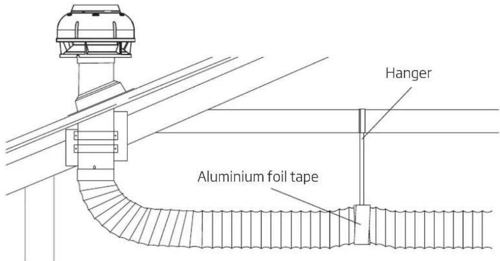
Support flexible duct by using hangers.
NOTE: Care shall be taken to minimize sagging or snaking of the duct between supports.
text_image
Hanger Aluminium foil tapeFigure 14 Examples of securing ducting
7. Parts List
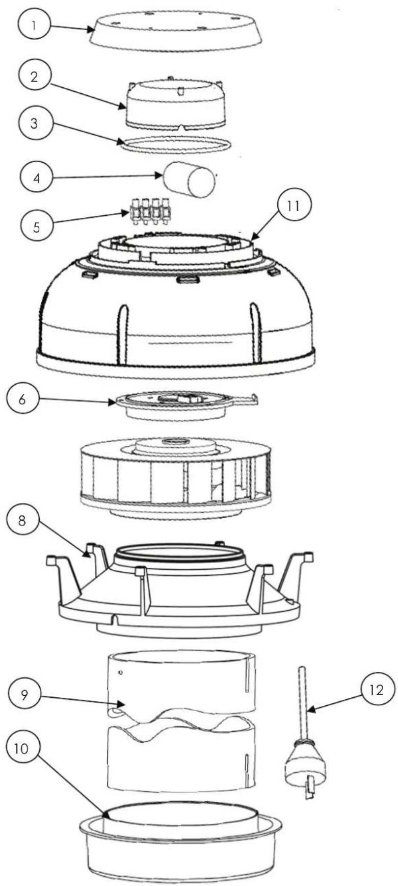
Parts List for Isodrive 900
text_image
Exploded view diagram of a mechanical device with numbered parts for identificationParts List for Isodrive 900
| Number Part | Description Quantity | |
| Number | ||
| 1 P40100 Terminal Block Cover 1 | ||
| 2 P40121 Wire Insulator Cap 1 | ||
| 3 P1061 O Ring 4 14 " ID 1 | ||
| 4 P1059 Capacitor 2μF 1 | ||
| 5 | P807 | Terminal Block 1 |
| 6 | P40102 Fan Plate - Motor Mount | 1 |
| 8 | P40122 | 900 Inlet Shroud Mount 1 |
| 9 P1069 | 150mm Slotted Pipe | 1 |
| 10 | P40114 Bell Mouth Adaptor | 1 |
| 11 | P40101 | Fan Shroud 1 |
| 12 P301 | Power Cable | 1 |
8. Maintenance
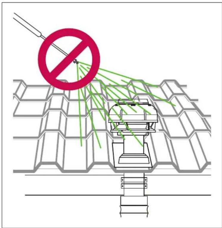
Roof Restoration or Cleaning
Before doing your roof restoration or cleaning, please completely cover the outside motor system and avoid all chemical contact.
text_image
Safety warning diagram showing a device emitting green spray from a red prohibition symbol over a grid-patterned roof.Figure 15 Avoid chemical contact to motor system

IMPORANT
Any damages caused by the use of chemical products are not covered by warranty.
Warranty (See warranty for more information)
BR500ST, BRW600ST and BRB700ST has a 5-Year replacement product warranty. This is a change over warranty. The consumer is responsible for any charges associated with removal of the faulty unit and installation of the new unit. The customer is also responsible for any freight charges incurred in this change over process.
Disclaimer
Under our policy of continuous product development, product specifications may change without notice. Prospective purchasers should therefore check with the retailer to ensure this publication correctly describes the products being offered for sale. All information supplied is to be used for general reference purposes only and is on the understanding that Schweigen Home Appliances will not be liable for any loss, liability or damage of whatever kind arising as a result of any reliance upon such information. All pictures used in the guide are for illustrative purposes only.
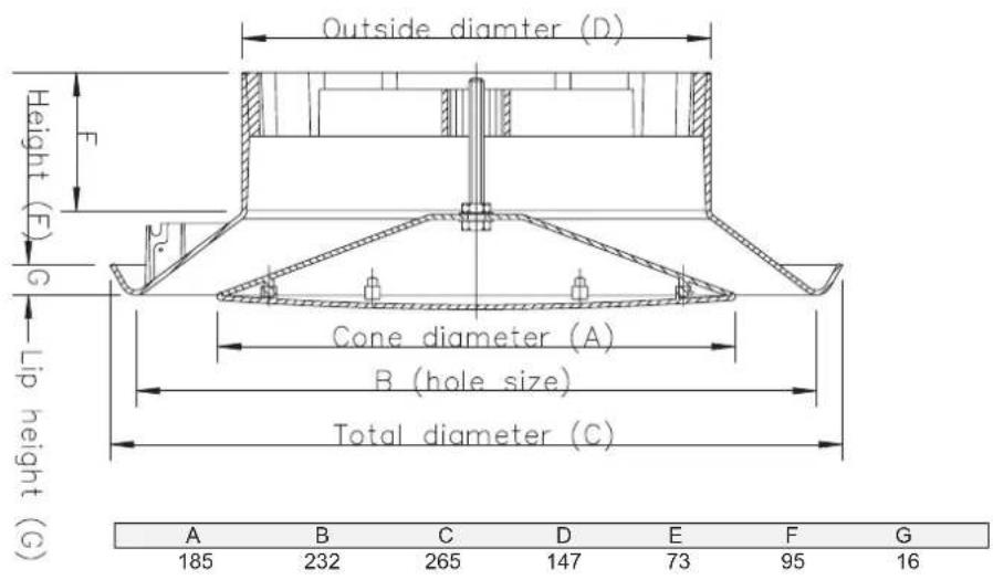
12. Vent Measurements
BR500ST - Measurements
text_image
Outside diameter (D) Height (F) G Lip height (G) Cone diameter (A) B (hole size) Total diameter (C) A B C D E F G 185 232 265 147 73 95 16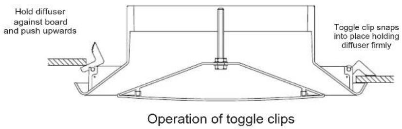
text_image
Hold diffuser against board and push upwards Toggle clip snaps into place holding diffuser firmly Operation of toggle clips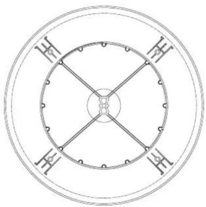
natural_image
Symmetrical circular diagram with four cross-shaped divisions and central dots, no text or symbols present.BR500ST Reducer
text_image
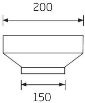
200 150BRW600ST - Measurements

text_image
303 200 52.735,8 44.5 89 194.35 255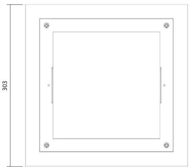
natural_image
Pure technical drawing of a square frame with corner markers and dimension label (303), no text or symbols present.Two timber support batons by installer
text_image
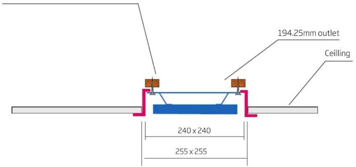
194.25mm outlet Ceiling 240 x 240 255 x 25512. Vent Measurements
BRB700ST - Measurements
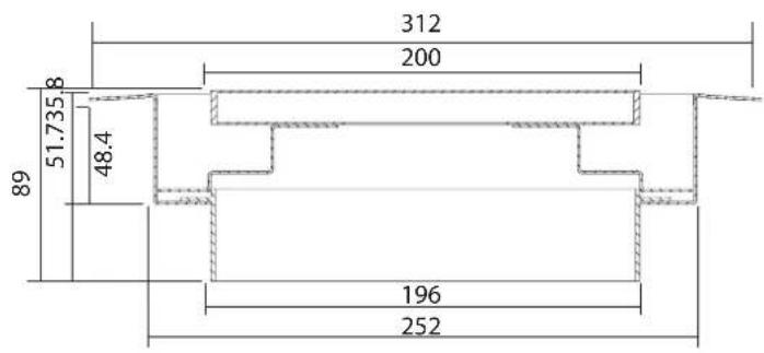
text_image
312 200 8 51.735 48.4 89 196 252
natural_image
Technical drawing of a square frame with circular side panels and a central rectangular cutout, no text or symbols present.Two timber support batons by installer
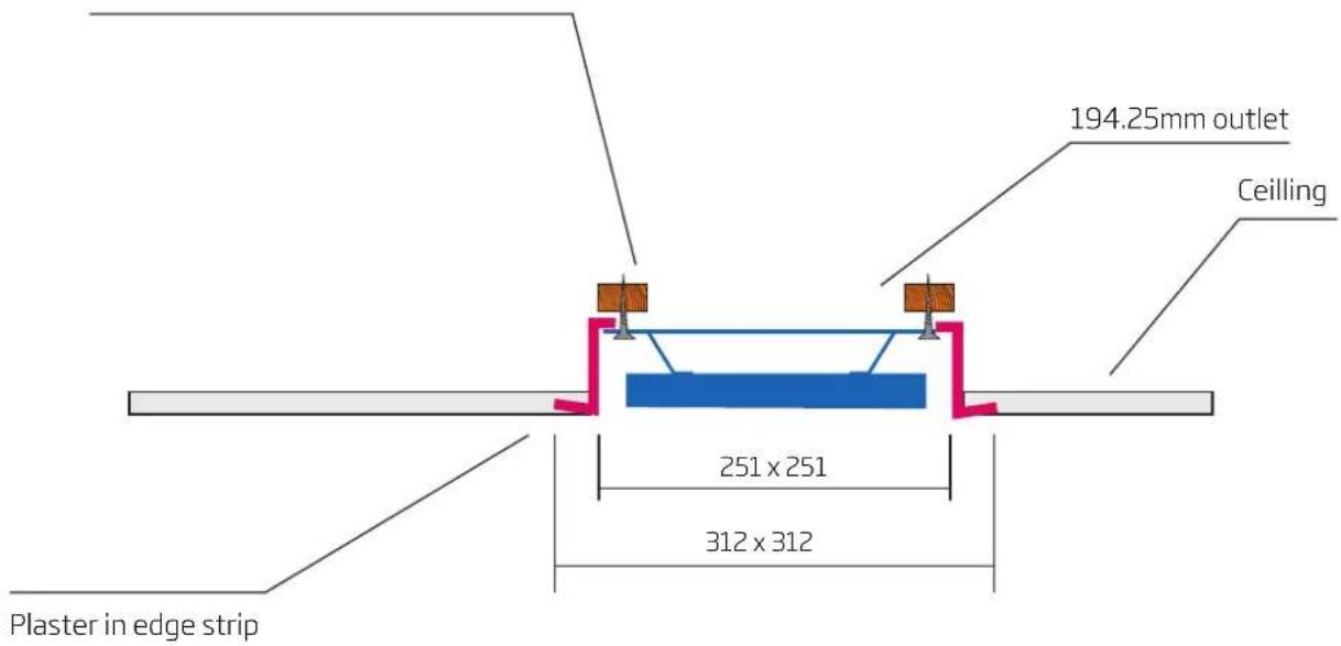
text_image
194.25mm outlet Ceiling 251 x 251 312 x 312 Plaster in edge stripschweigen
Australia 4/1-5 Lake Drive, Dingley Village, Victoria 3172. Phone 1300 881 693
Email sales@schweigen.com.au Web www.schweigen.com.au
New Zealand 5 Tolich Place, Henderson, Auckland 0610. Phone 0800 200 510
Email info.parex@emerson.com Web www.parex.co.nz