ES-5424P - Network switch Edimax - Free user manual and instructions
Find the device manual for free ES-5424P Edimax in PDF.

User questions about ES-5424P Edimax
0 question about this device. Answer the ones you know or ask your own.
Ask a new question about this device
Download the instructions for your Network switch in PDF format for free! Find your manual ES-5424P - Edimax and take your electronic device back in hand. On this page are published all the documents necessary for the use of your device. ES-5424P by Edimax.
USER MANUAL ES-5424P Edimax
No. 278, Xinhu 1st Rd., Neihu Dist., Taipei City, Taiwan
Email: support@edimax.com.tw
Edimax Technology Europe B.V.
Fijenhof 2, 5652 AE Eindhoven, The Netherlands
Email: support@edimax.nl
Edimax Computer Company
3350 Scott Blvd., Bldg.15 Santa Clara, CA 95054, USA
Live Tech Support: 1(800) 652-6776
Email: support@edimax.com
I Introducon....1
I-1 Overview....1
I-2 Package Content 1
I-3 Features....2
I-4 Product Components 2
I-4-1 Ports 2
I-4-2 LED Indicators 3
II Installaon 4
II-1 Mounng the Switch....4
II-1-1 Placement Tips....4
II-1-2 Rack Mounng....5
III Geng Started....7
III-1 Power....7
III-1-1 Connecng to Power....7
III-1-2 Connecng to Network 8
III-1-3 Power over Ethernet (PoE) Consideraons 9
III-1-4 Starng the Web-based Conguraon Ulity 10
III-1-5 Logging In....11
III-1-6 Logging Out.... 12
IV Web-based Switch Conguraon 13
IV-1 Administrator.... 14
IV-1-1 System Informaon....14
IV-1-2 Account/Password 15
IV-1-3 IP Conguraon 16
IV-1-3-1 IPv4 16
IV-1-3-2 IPv6....17
IV-1-4 SNMP Sengs.... 17
IV-1-4-1 SNMP View Table 18
IV-1-4-2 SNMP Group Table....19
IV-1-4-3 SNMP User Table 20
IV-1-4-4 SNMP Community Table 20
IV-1-4-5 SNMP Host Table 21
IV-1-4-6 SNMP Conguraon....22
IV-1-5 NTP Sengs....23
IV-1-6 Syslog Sengs 24
IV-1-7 Load Factory Default 25
IV-1-8 Conguraon 26
IV-1-8-1 Backup 26
IV-1-8-2 Restore 26
IV-1-9 Firmware Update 27
IV-2 Port Management....27
IV-2-1 Port Conguraon 27
IV-2-2 Port Mirror Funcon 29
IV-2-3 Broadcast Storm Protecon 30
IV-2-4 Bandwidth Control 32
IV-3 VLAN Conguraon....33
IV-3-1 VLAN Mode....33
IV-3-2 VLAN Group-based Entry Cong 34
IV-3-3 VLAN Tag-based Entry Cong 35
IV-3-4 VLAN Port Cong....37
IV-3-5 Protocol VLAN Cong....39
IV-3-6 QinQ Port Cong 40
IV-3-7 QinQ Index Cong 41
IV-4 QoS(Quality of Service) Conguraon....42
IV-4-1 QoS Group Member 42
IV-4-2 QoS Mode Set 43
IV-4-3 QoS Out Queue Aging 45
IV-4-4 QoS Remap 46
IV-4-5 Class of Service....47
IV-4-6 802.1q Base 48
IV-4-7 DSCP Base 49
IV-4-8 TCP/UDP Port Base 50
IV-5 ACL Conguraon 51
IV-5-1 ACL Prole List 51
IV-5-2 ACL Ctag Seings 57
IV-6 Security 59
IV-6-1 Port-MAC-IP Binding 59
IV-6-1-1 Port-MAC-IP Port Sengs....59
IV-6-1-2 Port-MAC-IP Entry Seng....61
IV-6-1-3 DHCP Snooping Entry Seng 62
IV-6-2 MAC Address Binding....62
IV-7 Advanced Features 65
IV-7-1 Spanning Tree Protocol STP 65
IV-7-1-1 STP Global Sengs 65
IV-7-1-2 STP Port Sengs 67
IV-7-1-3 MST Conguraon Idencaon 67
IV-7-1-4 STP Instance Sengs 69
IV-7-1-5 MSTP Port Informaon 69
IV-7-2 Trunk & Link Aggregaon....70
IV-7-3 IGMP Snooping 71
IV-7-3-1 IGMP Snooping Sengs....71
IV-7-3-2 IGMP Snooping Router Ports Seings 72
IV-7-3-3 IGMP Snooping Groups 73
IV-7-3-4 IGMP Snooping Ports 73
IV-7-4 MLD Snooping....74
IV-7-4-1 MLD Snooping Sengs 74
IV-7-4-2 MLD Snooping Router Ports Sengs 75
IV-7-4-3 MLD Snooping Groups 75
IV-7-4-4 MLD Snooping Ports....76
IV-7-4-5 DHCP Relay Agent 77
IV-7-5 Loop Detect....78
IV-7-6 GVRP 79
IV-7-7 Neighbor MACID 80
IV-8 Monitoring....81
IV-8-1 MIB Counter....81
IV-8-2 Scan MACID Lookup Table 83
IV-8-3 Syslog....84
Safety and Regulatory
Audience
This guide is for the networking professional managing the standalone PG28CB switch series. It is recommended that only professionals with experience working with Intelligent Technology INC. networking devices who are familiar with the Ethernet and local area networking terminology, should service the equipment.
Convenons
The following convenons are used in this manual to convey instrucons and informaon: Command descripons use these convenons:
- Commands and keywords are in boldface text.
- Arguments for which you supply values are in italic.
• Square brackets ([] ) mean oponal elements. - Braces ( { } group required choices, and vercal bars ( | ) separate the alternate elements.
- Braces and vercal bars within square brackets ({{ | }}) mean a required choice within an oponal element.
Interactive examples use these convenons:
- Nonprinting characters, such as passwords or tabs, are in angle brackets (< >). Notes and cauons use the following convenons and symbols:
- Note Means additional informaon. Notes contain additional useful informaon or references to material available outside of this document.
- Cauon Indicates that the reader must be careful. In a situation where a Cauon is listed, a user may cause equipment damage or loss of data.
Thank you for choosing a Edimax (PoE) WEB Smart Ethernet Switch. This device is designed to be operaonal right out-of-the-box as a standard bridge. In the default conguraon, it will forward packets between connecng devices aer powered up.
Before you begin installing the switch, make sure you have all of the package contents available, and a PC with a web browser for using web-based system management tools.
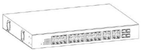
I-1 Overview
The Edimax ES-5424P is 24-Port Gigabit PoE+ Smart Managed Switch with 4 RJ45/SFP Combo respectively.
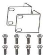
I-2 Package Content
Before using the product, check that the items listed below are included and in good condition. If any item does not accord with the table, please contact your dealer immediately.
natural_image
Line drawing of a rectangular electronic device with multiple ports and connectors (no text or symbols)1

2
3
- GS-5424PLC Switch
- Power Cord
- Rack-Mount Kit & Screws
I-3 Features
● Supports up to 24 10/100/1000Mbps Ethernet ports and 4 SFP slots or 4 mini-GBIC/SFP slots
- IEEE 802.3af/at PoE compliant to simplify deployment and installation
● Supports PoE up to 30W per port with 400W total power budget
● Automacally detects powered devices (PD) and power consumption levels
- IEEE 802.1Q VLAN allows network segmentation to enhance performance and security
● Supports Access Control List (ACL)
● Switch capacity: PG28CB: 56Gbps, Forwarding rate: 41.6Mbps
● Supports IGMP Snooping V1 / V2 / V3
● 8K MAC address table and 10K jumbo frames
● 19-inch rack-mountable metal case
I-4 Product Components
I-4-1 Ports
The following view applies to ES-5424P.

text_image
10/190M 1000M 1 2 3 4 5 6 7 8 9 10 11 12 13 14 15 16 17 18 19 20 21 22 23 24Figure 1 - Front View
| No. | Name | Descripon |
| 1 | 10/100/1000Mbps RJ-45 ports (1-24) | Designed to connect to network devices with a bandwidth of 10Mbps, 100Mbps or 1000Mbps. Each has a corresponding 10/100/1000Mbps LED. |
| 2 | RJ45/SFP combo Ports (SFP1, SFP2, SFP3, and SFP4) | Designed to install SFP modules or RJ-45 connect to network devices with a bandwidth of 1000Mbps. Each has a corresponding 1000Mbps LED. |
The following view applies to ES-5424P.

text_image
AC LINE 100-240 VAC 50/60 Hz 1Figure 2 - Rear View
| No. | Name | Descripon |
| 1 | AC power in | Support AC100 – 240V 50-60Hz. |
I-4-2 LED Indicators
The following view applies to ES-5424P.
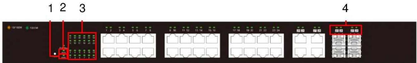
text_image
1 2 3 10/100M 1000M 1 2 3 4 5 6 7 8 9 10 11 12 13 14 15 16 17 18 19 20 21 22 23 24 4Figure 3 - Front View LED Indicators
| No. | Name | Descripon |
| 1 | Power | ● O: power o● On: power on |
| 2 | System | ● O: system not ready● On: system ready● Blinking: system boot-up |
| 3 | Port LED | LINK/ACT bi-color LED:● O: port disconnected or link fail● Green on: 1000Mbs connected, PoE power output on● Amber on: 10/100Mbs connected● Blinking: sending or receiving data |
| 4 | SFP LED | ● O: port disconnected or link fail● Green on: 1000Mbs connected |
This chapter describes how to install and connect your Edimax Switch. Read the following topics and perform the procedures in the correct order. Incorrect installaon may cause damage to the product.
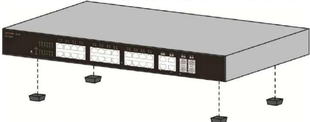
II-1 Mounng the Switch
There are two ways to physically set up the switch.
- Place the switch on a at surface. To place the switch on a desktop, install the four rubber feet (included) on the boom of the switch.
● Mount the switch in a standard rack (1 rack unit high).
II-1-1 Placement Tips
- Ambient Temperature — To prevent the switch from overheang, do not operate it in an area that exceeds an ambient temperature of 122^ F (50°C).
● Air Flow — Be sure that there is adequate air ow around the switch.
● Mechanical Loading — Be sure that the switch is level and stable to avoid any hazardous conditions. - Circuit Overloading — Adding the switch to the power outlet must not overload that circuit.
Follow these guidelines to install the switch securely.
● Put the switch in a stable place such as a desktop, to avoid it falling.
- Ensure the switch works in the proper AC input range and matches the voltage labeled.
- Ensure there is proper heat dissipion from and adequate venlaon around the switch.
- Ensure the switch's locaon can support the weight of the switch and its accessories.
natural_image
Illustration of a server rack with multiple ports and indicator lights (no text or symbols visible)Figure 4 - Desktop Installaon
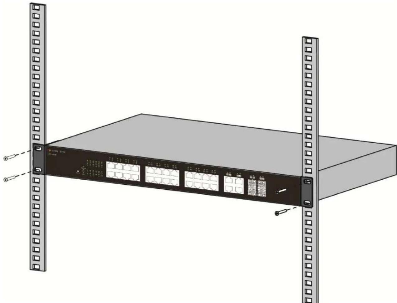
II-1-2 Rack Mounng
You can mount the switch in any standard size, 19-inch (about 48 ~cm ) wide rack. The switch requires 1 rack unit (RU) of space, which is 1.75 inches (44.45 mm) high.
For stability, load the rack from the boom to the top, with the heaviest devices on the boom. A top-heavy rack is likely to be unstable and may p over.
When mounng smaller switch products into a standard 19-inch rack, a pair of extension brackets (somemes referred to as ears) are needed to adapt the switch to the rack size.
These extension brackets are mounted on the switch using the screws provided in the kit, and have two holes that are used to then screw the switch into the rack.
An example of one type of these extension brackets is shown in the following gure.
A common problem that occurs during rack mounng is the distance between the screw holes on the rack. Some racks are made with a uniform distance between all of the holes, and others have the holes organized into groups (see photo on the next page for an example).
When organized into groups, the switch must be placed in the rack so that the holes in the extension brackets line up correctly.
- Align the moung brackets with the moung holes on the switch's side panels and secure the brackets with the screws provided.
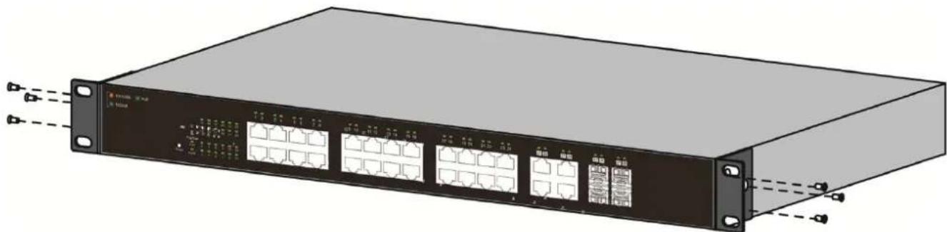
natural_image
Illustration of a network switch device with multiple Ethernet ports and connectors (no text or symbols visible)Figure 5 - Bracket Installaon
2. Secure the switch on the equipment rack with the screws provided.
natural_image
Illustration of a server rack unit with multiple Ethernet ports and mounting tabs (no text or symbols visible)Figure 6 - Rack Installaon
This secon provides an introducon to the web-based conguraon ulity, and covers the following topics:
● Powering on the device
- Connecng to the network
● Power over Ethernet (PoE) consideraons
● Starng the web-based conguraon ulity
III-1 Power
III-1-1 Connecng to Power
Power down and disconnect the power cord before servicing or wiring a switch.
Do not disconnect modules or cabling unless the power is rst switched o. The device only supports the voltage outlined in the type plate. Do not use any other power components except those specifically designated for the switch.
Disconnect the power cord before installaon or cable wiring.
The switch is powered by the AC 100-240 V 50/60Hz internal high-performance power supply. It is recommended to connect the switch with a single-phase three-wire power source with a neutral outlet, or a multifunctional computer professional source.
Connect the AC power connector on the back panel of the switch to the external power source with the included power cord, and check the power LED is on.

text_image
AC LINE 100-240 VAC 50/60 HzFigure 7 - Rear View AC Power Socket
III-1-2 Connecng to Network
To connect the switch to the network:
- Connect an Ethernet cable to the Ethernet port of a computer
- Connect the other end of the Ethernet cable to one of the numbered Ethernet ports of the switch. The LED of the port lights if the device connected is acve.
- Repeat Step 1 and Step 2 for each device to connect to the switch.
We strongly recommend using CAT-5E or beer cable to connect network devices. When connecng network devices, do not exceed the maximum cabling distance of 100 meters (328 feet). It can take up to one minute for aached devices or the LAN to be operational aer it is connected. This is normal behavior.
Connect the switch to end nodes using a standard Cat 5/5e Ethernet cable (UTP/STP) to connect the switch to end nodes as shown in the illustraon below.
Switch ports will automatically adjust to the characteriscs (MDI/MDI-X, speed, duplex) of the device to which the switch is connected.

natural_image
Illustration of a network switch device connected to a laptop (no text or symbols visible)Figure 8 - PC Connect
III-1-3 Power over Ethernet (PoE) Consideraons
For PoE switch models, consider the following informaon:
Devices considered a Power Sourcing Equipment (PSE), can support up to 30 Was per PoE port to a Powered Device (PD).
| Model | Power Dedicated to PoE | PoE Ports | PoE Standard Supported |
| ES-5424P | 240W | 1 to 24 | IEEE802.3at/af |
Ports 1-24 provide PoE power supply functionality with a maximum output power up to 30W each port. This can supply power to PDs such as internet phones, network cameras, wireless access points. Connect the switch PoE port directly to the PD port using a network cable.
When connecng switches capable of supplying PoE, consider the following informaon:
- Switch models with PoE funcon are PSEs. These models are capable of supplying DC power to aached PDs, such as VoIP phones, IP cameras, and wireless access points (APs). PoE switches. Additionally, PoE switches are capable of detectcng and supplying power to pre-standard legacy PoE Power Devices. Due to the support for legacy PoE, there is a possibility that PoE switches acng as a PSE may inadvertently detect and supply power an aached PSE, including other PoE switches. This false detecon may result in a PoE switch operang improperly and unable to supply power to aached PDs.
- The prevenon of a false detecon can be easily remedied by disabling PoE on the ports that are used to connect PSEs. Another simple pracce to prevent a false detecon is to rst power up a PSE device before connecng it to a PoE switch.
- When a device is falsely detected as a PD, disconnect the device from the PoE port and power recycle the device with AC power before reconnecting it to the PoE port.
III-1-4 Starng the Web-based Conguraon Utility
This secon describes how to navigate the web-based switch conguraon ulity.
Be sure to disable any pop-up blocker.
Browser Restricons
- If you are using older versions of Internet Explorer, you cannot directly use an IPv6 address to access the device. You can, however, use the DNS (Domain Name System) server to create a domain name that contains the IPv6 address, and then use that domain name in the address bar in place of the IPv6 address.
- If you have mulple IPv6 interfaces on your management staon, use the IPv6 global address instead of the IPv6 link local address to access the device from your browser.
Launching the Conguraon Utility
To open the web-based conguraon ulity:
- Open a Web browser.
- Enter the IP address of the device you are conguring in the address bar on the browser (factory default IP address is 192.168.2.1) and then press Enter.
When the device is using the factory default IP address, its power LED ashes connuously. When the device is using a DHCP assigned IP address or an administrator-congured stac IP address, the power LED is lit a solid color. Your computer's IP address must be in the same subnet as the switch. For example, if the switch is using the factory default IP address, your computer's IP address can be in the following range: 192.168.2.x (whereas x is a number from 2 to 254).
Aer a successful conncon, the login window displays.

text_image
Sign in http://admin123.dtm.net/2430 Your connection to the site is not provided Username: admin Password: mm/ Sign In CancelFigure 9 - Login Window
III-1-5 Logging In
The default username is admin and the default password is 1234. The rst me that you log in with the default username and password, you are required to enter a new password.
To log in to the device conguraon ulity:
- Enter the default user ID (admin) and the default password (admin).
- If this is the rst me that you logged on with the default user ID (admin) and the default password (admin) it is recommended that you change your password immediately. See "4.9.3. Administrator" for additional informaon.
When the login aempt is successful, the System Informaon window displays.
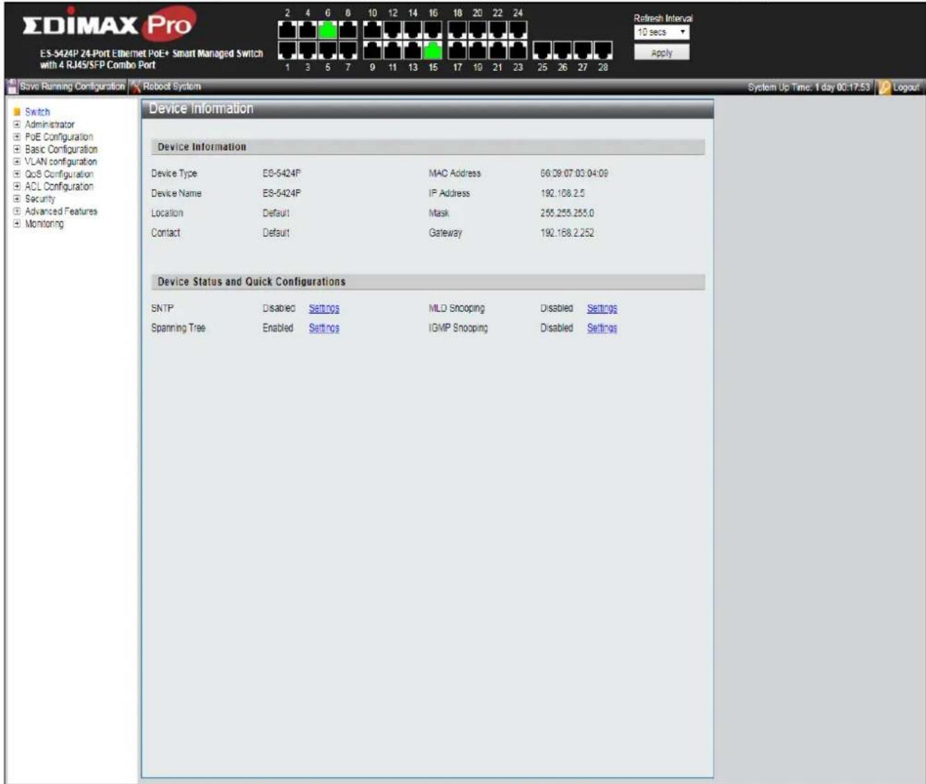
text_image
ES-DIMAX Pro ES-5424P 24-Port Ethernet PoE+ Smart Managed Switch with 4 RJ45/SFP Combo Port 1 3 5 7 9 11 13 15 17 10 21 23 25 26 27 28 Refresh Interval 10 secs Apply Save Running Configuration Robot System System Up Time: 1 day 00:17:53 Logout Switch Administrator PoE Configuration Basic Configuration VLAN configuration QoS Configuration ACL Configuration Security Advanced Features Monitoring Device Information Device Type ES-5424P MAC Address 66.09.07.03.04.09 Device Name ES-5424P IP Address 192.168.2.5 Location Default Mask 255.255.255.0 Contact Default Gateway 192.168.2.252 Device Status and Quick Configurations SNTP Disabled Settings MLD Snooping Disabled Settings Spanning Tree Enabled Settings IGMP Snooping Disabled SettingsFigure 10 - System Informaon
If you entered an incorrect username or password, an error message appears and the Login page remains displayed on the window.
If you are having problems logging in, please see the Launching the Conguraon Utility secon in the Administraon Guide for additional informaon.
III-1-6 Logging Out
By default, the applicaon logs out aer ten minutes of inacvity.
To manually logout, click Logout in the top right corner of any page.
When a meout occurs or you intenonally log out of the system, a message appears and the Login page appears, with a message indicang the logged-out state. Aer you log in, the applicaon returns to the initial page.
The PoE smart switch soware provides rich Layer 2 funconality for switches in your networks. This chapter describes how to use the web-based management interface (Web UI) to congregate the switch's features.
For the purposes of this manual, the user interface is separated into four seconds, as shown in the following gure:

text_image
EDIMAX Pro ES-5424P 24-Port Ethernet PoE+ Smart Managed Switch with 4 RJ45/SFP Combo Port 1 3 5 7 9 11 13 15 17 19 21 23 25 26 27 28 Refresh Interval 10 secs Apply Save Running Configuration Reboot System System Up Time: 1 day 00:17:53 Logout Switch Administrator PoE Configuration Basic Configuration VLAN configuration QoS Configuration ACL Configuration Security Advanced Features Monitoring Device Information Device Information Device Type ES-5424P MAC Address 66.09.07.03.04.09 Device Name ES-5424P IP Address 192.108.2.5 Location Default Mask 255.255.255.0 Contact Default Gateway 192.108.2.252 Device Status and Quick Configurations SNTP Disabled Settings MLD Snooping Disabled Settings Spanning Tree Enabled Settings ICMP Snooping Disabled Settings 3 2Figure 11 - User Interface
| No. | Name | Descripon |
| 1 | Conguraon menu | Navigate to locate speci switch funcons. |
| 2 | Conguraon sengs | Edit speci funcon sengs. |
| 3 | Switch’s informaon | Provides device informaon |
| 4 | Common toolbar & Switch’s current link status | Provides access to frequently used sengs. Green squares indicate the port link is up, while black squares indicate the port link is down. |
IV-1 Administrator
Use the Administrator pages to view system informaon and status.
IV-1-1 System Informaon
This page shows switch's MAC Address, Firmware Version, Upme, Device name, Comment, Locaon and Contact informaon. It also allows user to edit some system informaon.
To display the Device Informaon web page, click Administrator > System Information.
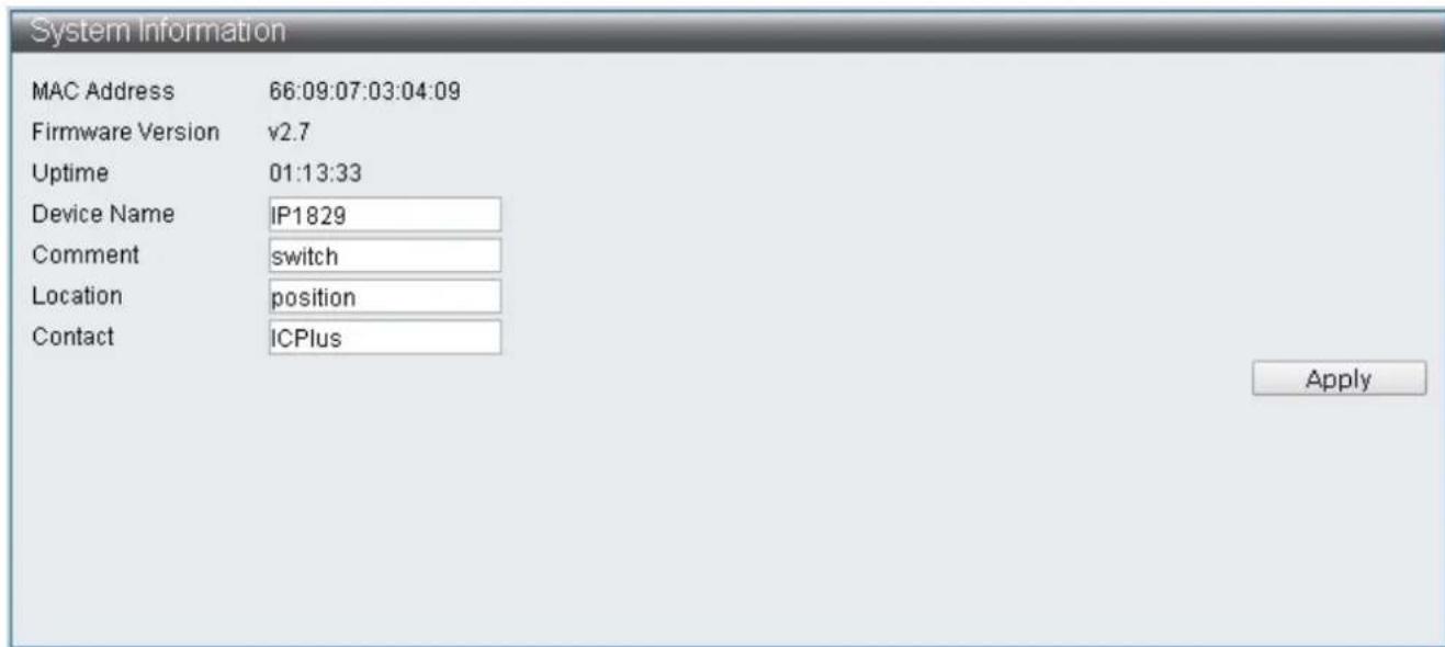
text_image
System Information MAC Address 66:09:07:03:04:09 Firmware Version v2.7 Uptime 01:13:33 Device Name IP1829 Comment switch Location position Contact ICPlus ApplyFigure 12 - Administrator > System Informaon
| Item | Descripon |
| MAC Address | Base MAC address of the switch. |
| Firmware Version | Current running rmware image version. |
| Upme | Display upme. |
| Device Name | System name of the switch. This name will also use as CLI prex of each line. (“Switch>” or “Switch#”). |
| Comment | Edit switch’s applicaon. |
| Locaon | Edit switch’s locaon. |
| Contact | Edit switch’s content. |
Note: Up to 15 characters can be entered.
Only the Device name, Comment, Locaon and Contact elds are able to be edited. Click "Apply" buon on the table to apply the changes made.
IV-1-2 Account / Password
This page displays the account and password that must be entered to log on the interface.
To display the User Account web page, click Administrator > Account / Password.

text_image
User Account User Name admin Password Confirm Password ApplyFigure 13 - Administrator > Account / Password
| Item | Descripon |
| User Name | Edit username |
| Password | Set password of the account. |
| Conrm Password | Set the same password of the account as in “Password”eld. |
Note: Up to 15 characters can be entered.
Enter the desired username and password. Click "Apply" buon on the table to apply the changes made.
IV-1-3 IP Conguraon
IP Conguraon allows users to assign IPv4 Address and IPv6 Address, or the IPv4 Address and IPv6 Address are automatically generated by DHCP Server.
IV-1-3-1 IPv4
This secon allows you to conjure the IPv4 address.
To display the IPv4 web page, click Administrator > IP Conguraon > IPv4.

text_image
IPv4 Static IPv4 Address IPv4 Address 192.168.2.1 Subnet Mask 255.255.255.0 Default Gateway 192.168.2.254 DNS Server DHCPv4 DHCPv4 Enable ApplyFigure 14 - Administrator > IP Conguraon > IPv4
| Item | Descripon |
| IPv4 Address | Edit IPv4 Address |
| Subnet Mask | Edit IPv4 Subnet Mask |
| Default Gateway | Edit IPv4 Default Gateway |
| DNS Server | Edit IPv4 DNS Server |
| DHCPv4 Enable | Enable IPv4 DHCP Server |
Note: The characters allowed to be entered are combinaons of "0\~9" and "."
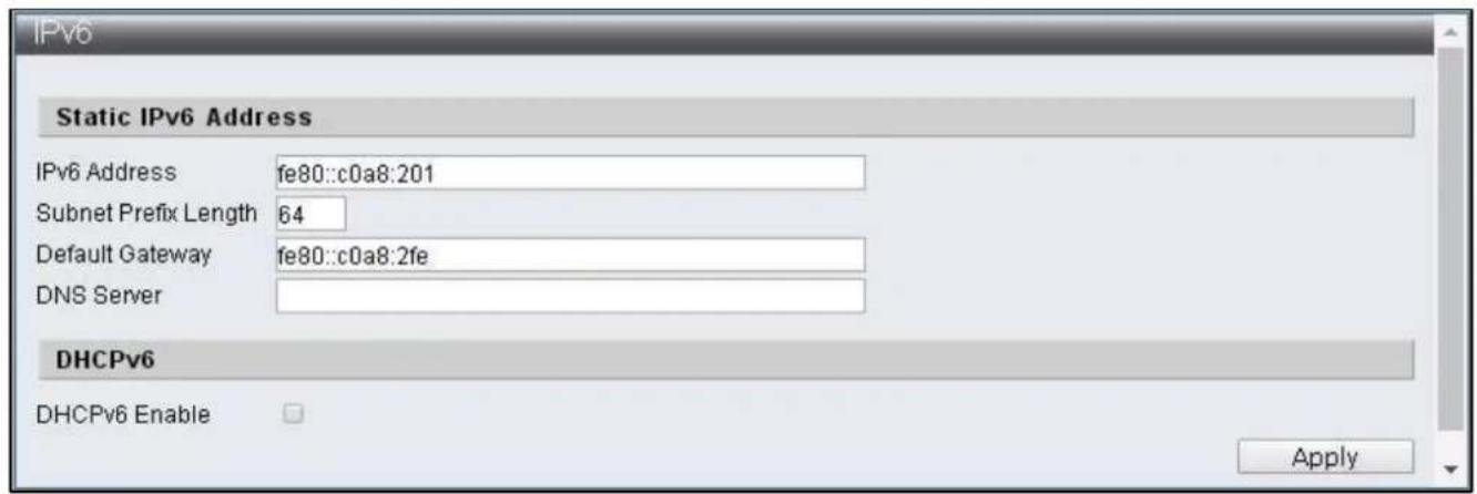
IV-1-3-2 IPv6
This secon allows you to conjure the IPv6 address.
To display the IPv4 web page, click Administrator > IP Conguraon > IPv6.
text_image
IPv6 Static IPv6 Address IPv6 Address fe80::c0a8:201 Subnet Prefix Length 64 Default Gateway fe80::c0a8:2fe DNS Server DHCPv6 DHCPv6 Enable ApplyFigure 15 - Administrator > IP Conguraon > IPv6
| Item | Descripon |
| IPv6 Address | Congure IPv6 Address |
| Subnet Prex Length | Congure IPv6 Subnet Prex Length |
| Default Gateway | Congure IPv6 Default Gateway |
| DNS Server | Congure IPv6 DNS Server |
| DHCPv6 Enable | Enable IPv6 DHCP Server |
Note: The characters allowed to be entered are combinaons of "0\~9", "a\~f" and "."
IV-1-4 SNMP Sengs
SNMP
Simple Network Management Protocol (SNMP) is an Internet Standard protocol for collecting and organizing informaon about managed devices on IP networks. The core of SNMP is a simple operaon program enabling management to monitor SNMP supported devices (hereaer referred to as agent). Simple Network Management Protocol (SNMP) consists of three parts including SNMP, MIB (Management Informaon Base) and SMI (Structure of Management Informaon). The SMI denes basic data types that make it convenient to describe managed objects and their behaviors. A management informaon base (MIB) is a database used for managing the enes in a communicaon network. MIB describe the system status and conguraon.
SNMP supports SNMPv1, SNMPv2 and SNMPv3, dierent versions can be selected to monitor Switch. The security levels provided by three versions in network management are dierent. The user authencaon of SNMPv1 and SNMPv2 is done by community string, which funcons as password. The manager and agent has to use the same community string in order to communicate. SNMPv3 use more complicated authencaon and additional security levels to encrypt the packets.
Trap is an unsolicited message sent by an SNMP agent to an SNMP manager when some event has occurred. Examples of trap conditions include, but are not limited to, when a port or module goes up or down, when the device is restarts, etc. Managers can designate type of event to be need.
IV-1-4-1 SNMP View Table
To congure and display the SNMP view table, click Administrator > SNMP Sengs > SNMP View Table.

text_image
SNMP View Settings View Name Subtree OID View Type Included ▼ Apply View Name Subtree Type Action systemview 1.3.6.1.2.1.1 included DeleteFigure 16 - Administrator > SNMP Sengs > SNMP View Table
| Item | Descripon |
| View Name | The SNMP view name. Its maximum length is 20 characters |
| Subtree OID | The OID idenes an object tree (MIB tree) that will be included or excluded |
| View Type | Specify the congured OID is Included or Excluded that an administrator can access |
| Delete | Remove the exisng view |
IV-1-4-2 SNMP Group Table
To congure and display the SNMP group table, click Administrator > SNMP Sengs > SNMP Group Table.
text_image
SNMP Group Settings Group Name Read View None Write View None Notify View None Security Model SNMPv1 Security Level NoAuthNoPriv Apply Group Name Read View Write View Notify View Security Model Security Level Action public systemview none systemview v1 noauth Delete public systemview none systemview v2c noauth DeleteFigure 17 - Administrator > SNMP Sengs > SNMP Group Table
| Item | Descripon |
| Group Name | Specify SNMP group name, and the maximum length is 20 characters. |
| Read View | Specify read access for the newly added group |
| Write View | Specify write access for the newly added group |
| Nofy View | Specify Trap View for the newly added group |
| Security Model | Specify the SNMP version for the newly added group |
| Security Level | Specify SNMP security level for the newly added group, only support SNMPv3NoAuthNoPriv –No authorizaon and no encryption for packets sentAuthNoPriv –Authorizaon is required, but no encrypon for packets sentAuthPriv – Both authorizaon and encrypon are required for packets sent |
| Delete | Remove the exisng group |
IV-1-4-3 SNMP User Table
To congregate and display the SNMP user table, click Administrator > SNMP Sengs > SNMP User Table.

text_image
SNMP User Settings User Name Group Name --Selected-- Auth-Protocol MD5 Priv-Protocol DES Apply User Name Group Name Auth-Protocol Priv-Protocol ActionFigure 18 - Administrator > SNMP Sengs > SNMP User Table
| Item | Descripon |
| User Name | Specify SNMP user name, and the maximum length is 20 characters |
| Group View | Specify the SNMP group to which the SNMP user belongs. |
| Auth-Protocol MD5 | Specify authencaon protocol, MD5 authencaon level is used |
| Priv-Protocol DES | Specify encrypon protocol, DES 56-bits encrypon is used |
IV-1-4-4 SNMP Community Table
To congregate and display the SNMP community table, click Administrator > SNMP Sengs > SNMP Community Table.
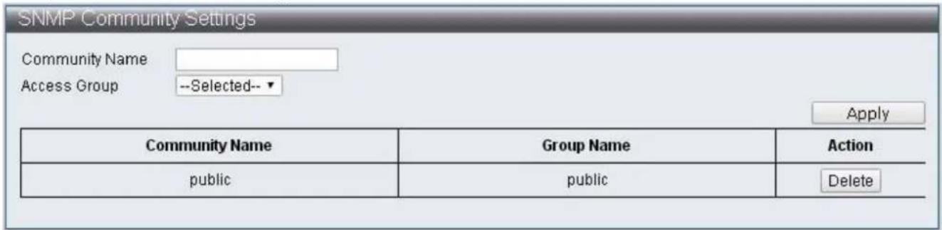
text_image
SNMP Community Settings Community Name Access Group --Selected-- Apply Community Name Group Name Action public public DeleteFigure 19 - Administrator > SNMP Sengs > SNMP Community Table
| Item | Descripon |
| Community Name | Specify the name for new SNMPv1 / SNMPv2 community string, its maximum length is 20 characters |
| Access Group | Specify the SNMP group to which the SNMP user belongs |
IV-1-4-5 SNMP Host Table
To congure and display the SNMP host table, click Administrator > SNMP Sengs > SNMP Host Table.
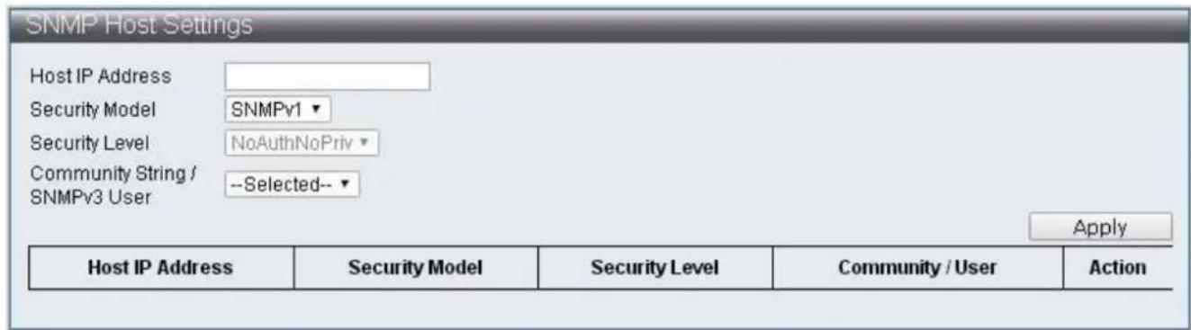
text_image
SNMP Host Settings Host IP Address Security Model SNMPv1 Security Level NoAuthNoPriv Community String / --Selected-- SNMPv3 User Apply Host IP Address Security Model Security Level Community / User ActionFigure 20 - Administrator > SNMP Sengs > SNMP Host Table
| Item | Descripon |
| Host IP Address | Specify the IP address of SNMP Trap |
| Security Model | Specify the SNMP version |
| Security Level | Specify SNMP security level, only support SNMPv3NoAuthNoPriv –No authorizaon and no encrypon for packets sentAuthNoPriv –Authorizaon is required, but no encrypon for packets sentAuthPriv – Both authorizaon and encrypon are required for packets sent |
| Community String/SNMPv3 User | Specify the community string or SNMPv3 user name |
IV-1-4-6 SNMP Conguraon
To congure and display the SNMP Conguraon, click Administrator > SNMP Sengs > SNMP Conguraon.

text_image
SNMP Configuration SNMP Setting SNMP State Disable ▼ SNMP Trap Disable ▼ SNMP Link Change Disable ▼ Traps Apply SNMP Link Change Traps Port Setting Port Selection 1 2 3 4 5 6 7 8 9 10 11 12 13 14 □ □ □ □ □ □ □ □ □ □ □ □ □ □ 15 16 17 18 19 20 21 22 23 24 25 26 27 28 □ □ □ □ □ □ □ □ □ □ □ □ □ □ ApplyFigure 21 - Administrator > SNMP Sengs > SNMP Conguraon
| Item | Descripon |
| SNMP State | Enable / Disable SNMP state |
| SNMP Trap | Enable / Disable SNMP Trap |
| SNMP Link Change Traps | Enable / Disable to send trap to remote host when link changes |
| Port Selecon | Check o the port that needs to be enabled to send traps for link changes detecon |
IV-1-5 NTP Sengs
The NTP (Network Time Protocol) provide network me vericaon.
To congure and display the NTP Sengs, click Administrator > NTP Sengs

text_image
NTP Settings System Time 1970/01/01 Thursday, 08:30:03 UTC+0800 State Disable Time Zone UTC + ▼ 08 : 00 Primary Server IP Secondary Server IP ApplyFigure 22 - Administrator > NTP Sengs
| Item | Descripon |
| System Time | Display system me |
| State | Enable / Disable NTP state |
| Time Zone | Specify mezone |
| Primary Server IP | Primary Server IP |
| Secondary Server IP | Secondary Server IP |
IV-1-6 Syslog Sengs
This page allow users to congregate syslog.
To congure and display the Syslog Sengs, click Administrator > Syslog Sengs.

text_image
Syslog Settings Global Setting Syslog state Apply Facility Setting Name State Facility dhcpd ✓ local1▼ gvrp ✓ local2▼ stp_lacp_d ✓ local3▼ multicast_table_d ✓ local4▼ misc_app ✓ local5▼ Apply Remote Server Setting Index Server Info. Priority IP ,port Loacl0 Loacl1 Loacl2 Loacl3 Loacl4 Loacl5 Loacl6 Loacl7 1 192.168.2.99 514 7▼ 7▼ 7▼ 7▼ 7▼ 7▼ 7▼ 7▼ 2 3 4 ApplyFigure 23 - Administrator > Syslog Sengs
| Item | Descripon |
| Syslog state | Enable Syslog |
| Name | Protocol |
| State | Enable / Disable protocol |
| Facility | Select Local number |
| Server Info. | Specify the server IP Address and port number |
| Priority | Select Local priory |
IV-1-7 Load Factory Default
To reset the Switch to the factory default sengs.
To congregate and display the Load Factory Default, click Administrator > Load Factory Default.

text_image
Load Default Setting Click "Load Default" to recover switch default setting excluding the IP address, User name and Password. Load DefaultFigure 24 - Administrator > Load Factory Default
| Item | Descripon |
| Load Default | Reset the Switch to the factory default sengs |
Note: Load Factory Default will reset the acon paern of ES-5424P to factory default seng but User Name, Password and IP Address will not be aected.
IV-1-8 Conguraon
This page allows users to congregate ES-5424P web Backup and Restore. A conguraon prole, current.tar.gz will be generated and saved through Backup by users, it contains the current conguraon of ES-5424P web. When users wish to restore the previous conguraon, current.tar.gz can be selected through Restore to overwrite the current seng.
IV-1-8-1 Backups
To congure and display the Load Factory Default, click Administrator > Conguraon > Backup.
Aer clicking "Apply" Buon, current.tar.gz conguraon prole will be automacally downloaded and saved to the directory assigned by users.

text_image
Backup Click "Apply" to download configuration file ApplyFigure 25 - Administrator > Conguraon > Backup.
IV-1-8-2 Restore
To congure and display the Restore, click Administrator > Conguraon > Restore

text_image
Recovery Select File Choose File No file chosen (Note: IP setting is excluded) ApplyFigure 26 - Administrator > Conguraon > Restore
| Item | Descripon |
| Select File | Select current.tar.gz conguraon prole to overwrite the current seng. |
Note: current.tar.gz conguraon prole will not change the IP Address.
IV-1-9 Firmware Update
This page allows users to update ES-5424P Firmware versions. Click "Choose File" to select the locaon where upgrade le is stored, then click the "Apply" to execute Firmware Update. The update is completed when waiing me ended.
To congure and display the Firmware Update, click Administrator > Firmware Update.

text_image
Firmware Update Current Firmware Version : Firmware Date : Enter the path and name of the upgrade file then click the "Apply" button below. Choose File No file chosen ApplyFigure 27 - Administrator > Firmware Update
| Item | Descripon |
| Choose File | Select Firmware Version for update. |
IV-2 Port Management
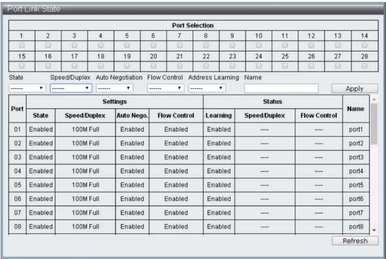
IV-2-1 Port Conguraon
This page, Port Conguraon, allows users to conjure every port, including sengs of Power up/down, Speed, Duplex, Auto-negoaon, Flow control, Address learning and Port name.
To congure and display the Port Conguraon, click Basic Conguraon > Port Conguraon.
text_image
Port Link State Port Selection 1 2 3 4 5 6 7 8 9 10 11 12 13 14 □ □ □ □ □ □ □ □ □ □ □ □ □ □ 15 16 17 18 19 20 21 22 23 24 25 26 27 28 □ □ □ □ □ □ □ □ □ □ □ □ □ □ State Speed/Duplex Auto Negotiation Flow Control Address Learning Name ----- ---- ---- Apply Port Settings Status Name State Speed/Duplex Auto Nego. Flow Control Learning Speed/Duplex Flow Control 01 Enabled 100M Full Enabled Enabled Enabled ---- ---- Uncut1 02 Enabled 100M Full Enabled Enabled Enabled ---- ---- Uncut2 03 Enabled 100M Full Enabled Enabled Enabled ---- ---- Uncut3 04 Enabled 100M Full Enabled Enabled Enabled ---- ---- Uncut4 05 Enabled 100M Full Enabled Enabled Enabled ---- ---- Uncut5 06 Enabled 100M Full Enabled Enabled Enabled ---- ---- Uncut6 07 Enabled 100M Full Enabled Enabled Enabled ---- ---- Uncut7 08 Enabled 100M Full Enabled Enabled Enabled ---- ---- Uncut8 RefreshFigure 28 - Basic Conguraon > Port Conguraon
| Item | Descripon |
| Port Selecon | Select the port |
| Sengs | Current conguraon |
| Status | The current link status |
| State | Power up/down |
| Speed/Duplex | Select port speed and duplex |
| Auto Negoaon | Enable / Disable Auto-negoaon |
| Flow Control | Enable / Disable Flow control |
| Address Learning | Enable / Disable address learning |
| Name | Specify the port name |
| Refresh | Refresh the page |
IV-2-2 Port Mirror Funcon
Port Mirroring is a method of monitoring network trac where the switch forwards a copy of each incoming and/or outgoing packet from source port to desnaon port. Under certain scenarios, network trac can be monitored for other applicaons such as diagnoscs or management.
To congure and display the Port Mirror Funcon, click Basic Conguraon > Port Mirror Funcon.

text_image
Port Mirror Function Source Port Selection 1 2 3 4 5 6 7 8 9 10 11 12 13 14 □ □ □ □ □ □ □ □ □ □ □ □ □ □ 15 16 17 18 19 20 21 22 23 24 25 26 27 28 □ □ □ □ □ □ □ □ □ □ □ □ □ □ Destination Port Selection 1 2 3 4 5 6 7 8 9 10 11 12 13 14 □ □ □ □ □ □ □ □ □ □ □ □ □ □ 15 16 17 18 19 20 21 22 23 24 25 26 27 28 □ □ □ □ □ □ □ □ □ □ □ □ □ □ State Method Äpply Disable BothFigure 29 - Basic Conguraon > Port Mirror Funcon
| Item | Descripon |
| Source Port Selecon | Select the number of the ports whose network acvity will be monitored. |
| Desnaon Port Selecon | Select the number of the port that will be used to monitor the acvity of the monitored port. |
| State | Enable / Disable monitoring funcon. |
| Method | Specify ingress, egress or both methods |
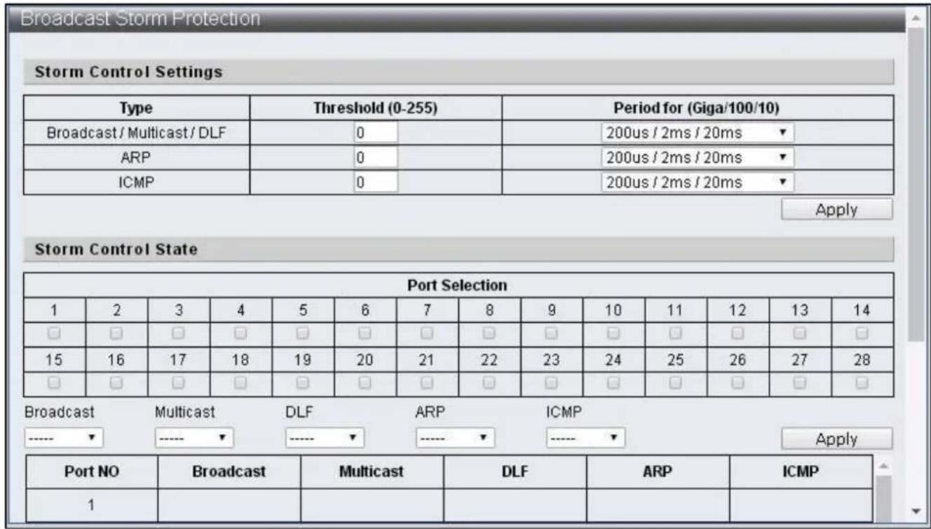
IV-2-3 Broadcast Storm Protecon
The Broadcast Storm Protecon feature provides the ability to control the receive rate of broadcast, mulcast, DLF, ARP and ICMP packets for every port. The maximum threshold is 255 per me unit within the control period.
To congure and display the Broadcast Storm Protecon, click Basic Conguraon > Broadcast Storm Protecon.
text_image
Broadcast Storm Protection Storm Control Settings Type Threshold (0-255) Period for (Giga/100/10) Broadcast / Multicast / DLF 0 200us / 2ms / 20ms ARP 0 200us / 2ms / 20ms ICMP 0 200us / 2ms / 20ms Apply Storm Control State Port Selection 1 2 3 4 5 6 7 8 9 10 11 12 13 14 □ □ □ □ □ □ □ □ □ □ □ □ □ 15 16 17 18 19 20 21 22 23 24 25 26 27 28 □ □ □ □ □ □ □ □ □ □ □ □ □ Broadcast Multicast DLF ARP ICMP -----▼-----▼-----▼-----▼-----▼ Apply Port NO Broadcast Multicast DLF ARP ICMP 1Figure 30 - Basic Conguraon > Broadcast Storm Protecon
| Item | Descripon |
| Type | Various storm control types:Broadcast : broadcast packetsMulcast : one-to- many transmissions of packets and the 40-bit of desnaon MAC is set to 1.DLF : the desnaon MAC address not included in MAC address tableARP : ARP packetICMP : ICMP packet |
| Threshold | The maximum number of assigned packets can be received by port within the receival period. |
| Period for (Giga/100/10) | Specify the receival period. |
| Port Selecon | Select the seng ports. |
| Broadcast | Enable / Disable the control on broadcast packets. |
| Mulcast | Enable / Disable the control on mulcast packets. |
| DLF | Enable / Disable control on unknown desnaon MAC packets. |
| ARP | Enable / Disable control on ARP packets. |
| ICMP | Enable / Disable control on ICMP packets. |
IV-2-4 Bandwidth Control
This page provides the bandwidth control on transming and receiving data rates of each port, the default seng is the maximum link speed.
To congure and display the Bandwidth Control, click Basic Conguraon > Bandwidth Control.
| Port Selection | |||||||||||||
| 1 | 2 | 3 | 4 | 5 | 6 | 7 | 8 | 9 | 10 | 11 | 12 | 13 | 14 |
| ☐ | ☐ | ☐ | ☐ | ☐ | ☐ | ☐ | ☐ | ☐ | ☐ | ☐ | ☐ | ☐ | ☐ |
| 15 | 16 | 17 | 18 | 19 | 20 | 21 | 22 | 23 | 24 | 25 | 26 | 27 | 28 |
| ☐ | ☐ | ☐ | ☐ | ☐ | ☐ | ☐ | ☐ | ☐ | ☐ | ☐ | ☐ | ☐ | ☐ |
| Ingress Rate (kbps) Egress Rate (kbps) (1~1000000) (1~1000000) Apply | |||||||||||||
| Port | Ingress Rate (kbps) | Egress Rate (kbps) | |||||||||||
| 01 | unlimited | unlimited | |||||||||||
| 02 | unlimited | unlimited | |||||||||||
| 03 | unlimited | unlimited | |||||||||||
| 04 | unlimited | unlimited | |||||||||||
| 05 | unlimited | unlimited | |||||||||||
| 06 | unlimited | unlimited | |||||||||||
| 07 | unlimited | unlimited | |||||||||||
| 08 | unlimited | unlimited | |||||||||||
| 09 | unlimited | unlimited | |||||||||||
| 10 | unlimited | unlimited | |||||||||||
Figure 31 - Basic Conguraon > Bandwidth Control
| Item | Descripon |
| Port Selecon | Select the sengs port |
| Ingress Rate | Specify the rate of packet received |
| Egress Rate | Specify the rate of packets transmied |
| Refresh | Refresh the status of bandwidth Control |
IV-3 VLAN Conguraon
IV-3-1 VLAN Mode
A virtual local area network, virtual LAN or VLAN is able to congregate one or more ports into independent domain according to logic, the information between each domain is not able to communicate; thus the bandwidth is saved and performance is increased to provide a certain level of security for the network. The switch supports IEEE 802.1Q and Port-Based VLAN, the untagged ports can remove the 802.1Q tag to maintain the compatibility with equipment that does not support IEEE 802.1Q.
To congure and display the VLAN Mode, click VLAN Conguraon > VLAN Mode.

text_image
VLAN Mode VLAN Mode ○ Tag VLAN ● Group VLAN Tag Method ● by Tag ○ by Port Egress Frame □ Multicast □ Unicast □ ARP ApplyFigure 32 - VLAN Conguraon > VLAN Mode
| Item | Descripon |
| VLAN Mode | Tag Vlan: Specify the VID of each Entry according to the Tag based Entry seng and which port should be VLAN members of such VID.Group Vlan: Specify the port which is a Group VLAN member according to Group-based Entry sengs. |
| Tag Method | The seng is only eecve under the Tag VLAN modeBy Tag: The transming port will add or remove tag according to the value assigned to the port of Tag-based EntryBy Port: The transming port will add or remove tags according to the Tagging value assigned to the port of VLAN port cong web page |
| Egress Frame | Transmit the selected type of packets (Mulcast, Unicast and ARP) among dierent VLAN through egress rule |
IV-3-2 VLAN Group-based Entry Cong
To congure and display the VLAN Group-based Entry Cong, click VLAN Conguraon > VLAN Group-based Entry Cong.

text_image
VLAN Group-based Entry config Group Name: GROUP Member Port 1 2 3 4 5 6 7 8 9 10 11 12 13 14 □ □ □ □ □ □ □ □ □ □ □ □ □ □ 15 16 17 18 19 20 21 22 23 24 25 26 27 28 □ □ □ □ □ □ □ □ □ □ □ □ □ □ Add Modify Group Table Group Name Group Member Illustration test 1-5 Edit Delete aaa 1,6,8 Edit DeleteFigure 33 - VLAN Conguraon > VLAN Group-based Entry Cong
| Item | Descripon |
| Group Name | Specify the Group VLAN name |
| Group Member Port | Specify Group VLAN member |
| Add | Add Group VLAN |
| Edit | Edit the selected Group VLAN |
| Modify | Modify the contents of selected Group VLAN |
| Delete | Deleted the selected Group VLAN |
IV-3-3 VLAN Tag-based Entry Cong
To congure and display the VLAN Tag-based Entry Cong, click VLAN Conguraon > VLAN Tag-based Entry Cong.
| Name | State | VID | Don't care | Add Tag | Remove Tag | Forbidden | Priority | GVRP forward | Action | |
| default | static | 1 | 1-28 | 0 | 0 | 0 | 0 | Deny | Edit | Delete |
| protocol_vlan1 | static | 4081 | 1-28 | 0 | 0 | 0 | 0 | Deny | Edit | Delete |
| protocol_vlan2 | static | 4082 | 1-28 | 0 | 0 | 0 | 0 | Deny | Edit | Delete |
| protocol_vlan3 | static | 4083 | 1-28 | 0 | 0 | 0 | 0 | Deny | Edit | Delete |
| protocol_vlan4 | static | 4084 | 1-28 | 0 | 0 | 0 | 0 | Deny | Edit | Delete |
Figure 34 - VLAN Conguraon > VLAN Tag-based Entry Cong
| Item | Descripon |
| Add | Add Tag VLAN. Enter default Tag VLAN name and its VID according to instrucons |
| Edit | Edit the selected Tag VLAN |
| Delete | Delete the selected Tag VLAN |

Figure 35 - VLAN Conguraon > VLAN Tag-based Entry Cong > Edit > VLAN Tag-based Entry cong
| Item | Descripon |
| VLAN Name | Tag VLAN name |
| VID | The VID of this Tag VLAN |
| Priority | Specify the Tag VLAN priority |
| GVRP forward | When GVRP is enabled, specify if this Tag VLAN will be transmied through GVRP |
| VLAN Member | Specify the Tag VLAN member |
| Don’t care | It is a VLAN member |
| Add | It is a VLAN member, add tag to the packets transmied by this Port |
| Remove | It is a VLAN member, remove tag to the packets transmied by this Port |
| Forbidden | Congure this Port to be unable to register the Tag VLAN through GVRP |
| Not member | It is not a VLAN member |
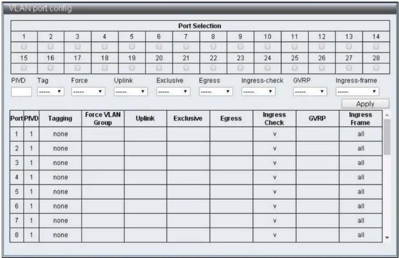
IV-3-4 VLAN Port Cong
To congure and display the VLAN Port Cong, click VLAN Conguraon > VLAN Port Cong.
text_image
VLAN port config Port Selection 1 2 3 4 5 6 7 8 9 10 11 12 13 14 □ □ □ □ □ □ □ □ □ □ □ □ □ □ 15 16 17 18 19 20 21 22 23 24 25 26 27 28 □ □ □ □ □ □ □ □ □ □ □ □ □ □ PIVD Tag Force Uplink Exclusive Egress Ingress-check GVRP Ingress-frame Apply Port PIVD Tagging Force VLAN Group Uplink Exclusive Egress Ingress Check GVRP Ingress Frame 1 1 none 2 1 none 3 1 none 4 1 none 5 1 none 6 1 none 7 1 none 8 1 noneFigure 36 - VLAN Conguraon > VLAN Port Cong
| Item | Descripon |
| Port Selecon | Select the sengs port |
| PVID | Specify the Port VID |
| Tagging | Specify if the packets transmied by Port should add or remove VLAN Tag |
| Force VLAN Group | Specify if priority is set according to Group VLAN |
| Uplink | Congure as uplink port. When the desnaon Port of packets are not in the same VLAN, packets will be transmied from uplink port automacally |
| Exclusive | Congure as exclusive port, packets cannot be transmied between exclusive ports |
| Egress | Congure as egress port, when the desnaon port of packets is not in the same VLAN, such packets can sll be transmied to the desnaon port through egress rule |
| Ingress Check | Enable ingress check funcons, check if Port is VLAN member through VID |
| GVRP | Enable /Disable Port GVRP funcons |
| Ingress Frame | Congure the assigned frame to enable forward funcon |
IV-3-5 Protocol VLAN Cong
To congure and display the Protocol VLAN Cong, click VLAN Conguraon > Protocol VLAN Cong.

text_image
Protocol VLAN config ✓ Protocol VLAN enable Enable No. VID Protocol type Protocol Select □ 1 4081 0x0 Ether_type ▼ □ 2 4082 0x0 Ether_type ▼ □ 3 4083 0x0 Ether_type ▼ □ 4 4084 0x0 Ether_type ▼ ApplyFigure 37 - VLAN Conguraon > Protocol VLAN Cong
| Item | Descripon |
| Protocol VLAN enable | Enable / Disable Protocol VLAN |
| Enable check box | Select the group to be enabled |
| VID | Specify the VID, when the packets match with Protocol set up, this VID will be used to search for VLAN Member |
| Protocol type | Specify Protocol type |
| Protocol Select | Ether Type: The Protocol type value should be larger than 0x0600 when the Ether Type is specied, the format is DA + SA + Protocol typeLLC: the format isDA + SA + Length + Protocol type RFC 1042: the format is DA + SA + Length + AAAA03 + 000000 + Protocol type |
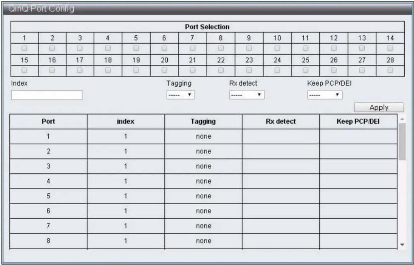
IV-3-6 QinQ Port Cong
To congure and display the QinQ Port Cong, click VLAN Conguraon > QinQ Port Cong.
text_image
QinQ Port Config Port Selection 1 2 3 4 5 6 7 8 9 10 11 12 13 14 □ □ □ □ □ □ □ □ □ □ □ □ □ □ 15 16 17 18 19 20 21 22 23 24 25 26 27 28 □ □ □ □ □ □ □ □ □ □ □ □ □ □ Index Tagging Rx detect Keep PCP/DEI Apply Port Sug Index Tagging Rx detect Keep PCP/DEI 1 1 none 2 1 none 3 1 none 4 1 none 5 1 none 6 1 none 7 1 none 8 1 noneFigure 38 - VLAN Conguraon > QinQ Port Cong
| Item | Descripon |
| Port Selecon | Select seng port |
| Index | When the Index is selected, the Service Tag of that Index is specied in QinQ Index Cong webpage |
| Tagging | Add:Add Service Tag to packets enter / exit the Port. If the packets entered carries Service Tag, then modify or replace Service Tag according to if Rx detect is enabledRMV:Service Tag can be removed only when Rx detect is enabled |
| Rx detect | Enable / Disable the Service Tag check on packets entering the port |
| Keep PCP/DEI | When modifying the Service Tag added to the packets, specify is original PCP and DEI values are kept. |
IV-3-7 QinQ Index Cong
To congure and display the QinQ Index Cong, click VLAN Conguraon > QinQ Index Cong.
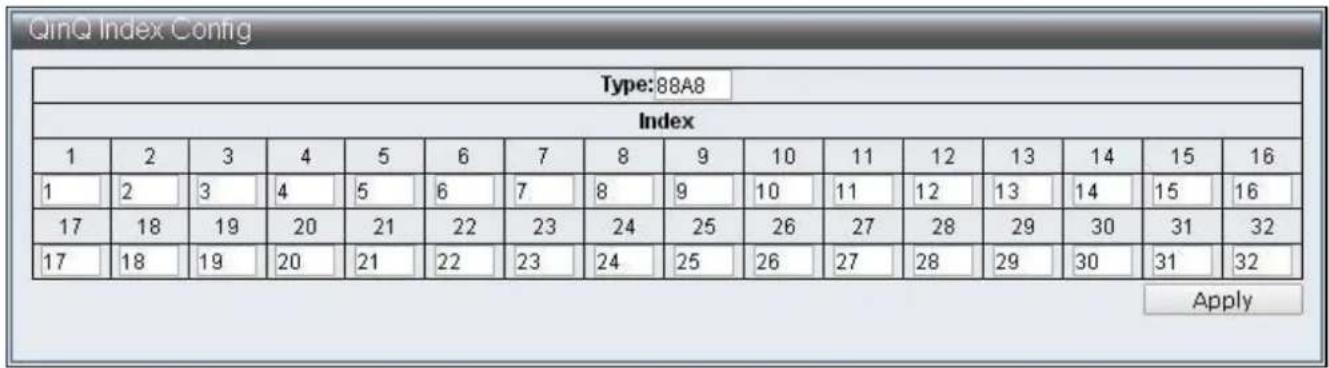
text_image
QinQ Index Config Type:88A8 Index 1 2 3 4 5 6 7 8 9 10 11 12 13 14 15 16 1 2 3 4 5 6 7 8 9 10 11 12 13 14 15 16 17 18 19 20 21 22 23 24 25 26 27 28 29 30 31 32 17 18 19 20 21 22 23 24 25 26 27 28 29 30 31 32 ApplyFigure 39 - VLAN Conguraon > QinQ Index Cong
| Item | Descripon |
| Type | Specify the Type of Service Tag |
| Index | Specify the Service Tag match with Index |
IV-4 QoS(Quality of Service) Conguraon
QoS is an implementation of the IEEE 802.1p standard that reserve bandwidth for important funcons that require a larger bandwidth or that might have a higher priority. QoS can create larger bandwidth, less critical trac is limited, and therefore excessive bandwidth can be saved. Every physical port on the switch has its own queue to realize the applicaons of various packets.
IV-4-1 QoS Group Member
To congure and display the QoS Group Member, click QoS Conguraon > QoS Group Member.
| QoS Group Member | ||||||||||||||
| Port | 1 | 2 | 3 | 4 | 5 | 6 | 7 | 8 | 9 | 10 | 11 | 12 | 13 | 14 |
| Group A | ||||||||||||||
| Group B | ||||||||||||||
| Port | 15 | 16 | 17 | 18 | 19 | 20 | 21 | 22 | 23 | 24 | 25 | 26 | 27 | 28 |
| Group A | ||||||||||||||
| Group B | ||||||||||||||
| Apply | ||||||||||||||
| Group | Member Port | |||||||||||||
| A | 1-28 | |||||||||||||
| B | 0 | |||||||||||||
Figure 40 – QoS Conguraon > QoS Group Member
| Item | Descripon |
| Group A | Select Group A member Ports |
| Group B | Select Group B member Ports |
IV-4-2 QoS Mode Set
To congure and display the QoS Mode Set, click QoS Conguraon > QoS Mode Set
| Group | Queue Mode | Queue Method | Queue Ratio (0-255) | Queue Max Bandwidth (0-255) | Unit (BW throttle period / TWRR tickle unit) | |
| A | First-In-First-Out | WRR | Q0:0 Q1:0 Q2:0 Q3:0 Q4:0 Q5:0 Q6:0 Q7:0 | Q0:0 Q1:0 Q2:0 Q3:0 Q4:0 Q5:0 Q6:0 Q7:0 | 64Kbps / 51.2ms | |
| B | First-In-First-Out | WRR | Q0:0 Q1:0 Q2:0 Q3:0 Q4:0 Q5:0 Q6:0 Q7:0 | Q0:0 Q1:0 Q2:0 Q3:0 Q4:0 Q5:0 Q6:0 Q7:0 | 64Kbps / 51,2ms | |
Figure 41 – QoS Conguraon > QoS Mode Set
| Item | Descripon |
| Queue Mode | Select the default mode for each Group, there are six modes:First-In-First-OutSPx1+WRR/WFQ/BW/TWRRx7SPx2+WRR/WFQ/BW/TWRRx6SPx4+WRR/WFQ/BW/TWRRx4SPx8 |
| Queue Method | Select the type of Queue scheduling:1. WRRSpecify the priority rao of each Queue, using number of packets as measuring unit2. WFQSpecify the weight rao of each Queue, 4096 Bytes is the measuring unit3. BwassureDynamic Bandwidth Management, specify the bandwidth and its maximum value of each Queue. The bandwidth specicaon method is Queue Rao x BW throle period, when Queue bandwidth reach its bandwidth seng, excessive bandwidth will connue to increase to maximum bandwidth4. BwlimitStac Bandwidth Management specify the maximum bandwidth of each Queue, the bandwidth specicaon method is Queue Rao x BW throle period5. TWRRSpecify the transmission cycle of each Queue, its cycle specicaon method should be Queue Rao x TWRR ckle unit |
| Queue Rao | Specify the priority of each mode |
| Queue Max Bandwidth | Specify the maximum bandwidth under Bwassure method |
| Unit (BW throle period / TWRR ckle unit) | Specify the weight unit of each mode |
IV-4-3 QoS Out Queue Aging
To congure and display the QoS Out Queue Aging, click QoS Conguraon > QoS Out Queue Aging
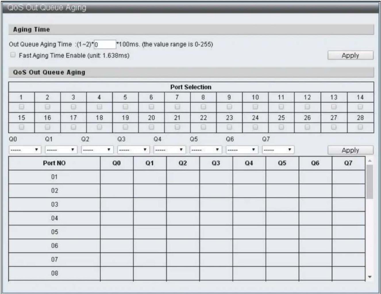
text_image
QoS Out Queue Aging Aging Time Out Queue Aging Time : (1~2)*0 *100ms. (the value range is 0-255) Fast Aging Time Enable (unit: 1.638ms) Apply QoS Out Queue Aging Port Selection 1 2 3 4 5 6 7 8 9 10 11 12 13 14 □ □ □ □ □ □ □ □ □ □ □ □ □ □ 15 16 17 18 19 20 21 22 23 24 25 26 27 28 □ □ □ □ □ □ □ □ □ □ □ □ □ □ Q0 Q1 Q2 Q3 Q4 Q5 Q6 Q7 ----▼-----▼-----▼-----▼-----▼-----▼-----▼-----▼ Apply Port NO Q0 Q1 Q2 Q3 Q4 Q5 Q6 Q7 01 ,Q0 02 ,Q1 03 ,Q2 04 ,Q3 05 ,Q4 06 ,Q5 07 ,Q6 08 ,Q7Figure 42 – QoS Conguraon > QoS Out Queue Aging
| Item | Descripon |
| Out Queue Aging Time | Specify the Queue Aging Time |
| Fast Aging Time Enable | Specify Aging Time conversion units, change from 100ms to 1.638ms |
| Port Select | Select default Ports |
| Q0 ~ Q7 | Select the Queue with Out Queue Aging Time is enabled by default |
IV-4-4 QoS Remap
To congure and display the QoS Remap, click QoS Conguraon > QoS Remap
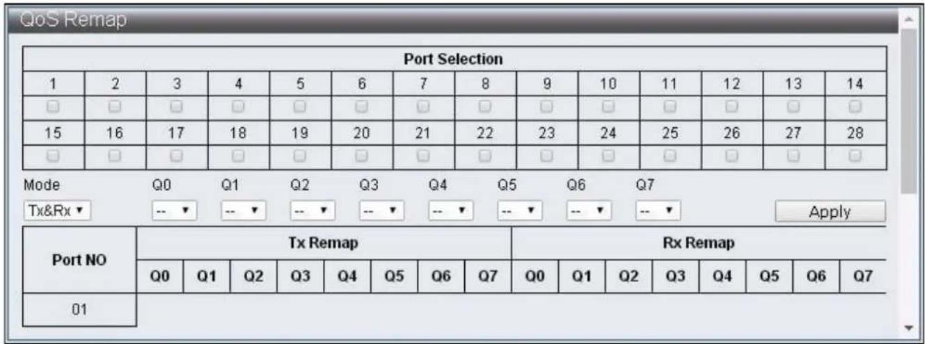
text_image
QoS Remap Port Selection 1 2 3 4 5 6 7 8 9 10 11 12 13 14 □ □ □ □ □ □ □ □ □ □ □ □ □ □ □ 15 16 17 18 19 20 21 22 23 24 25 26 27 28 □ □ □ □ □ □ □ □ □ □ □ □ □ □ Mode Q0 Q1 Q2 Q3 Q4 Q5 Q6 Q7 Tx&Rx▼ --▼ --▼ --▼ --▼ --▼ --▼ --▼ --▼ Apply Port NO Tx Remap Rx Remap Q0 Q1 Q2 Q3 Q4 Q5 Q6 Q7 Q0 Q1 Q2 Q3 Q4 Q5 Q6 Q7 01Figure 43 – QoS Conguraon > QoS Remap
| Item | Descripon |
| Port Selecon | Select sengs Port |
| Mode | Mode selecons of Tx,Rx or Tx&Rx |
| Q0 ~ Q7 | Select the Queue Number mapped to each Queue by default |
IV-4-5 Class of Service
To congure and display the Class of Service, click QoS Conguraon > Class of Service
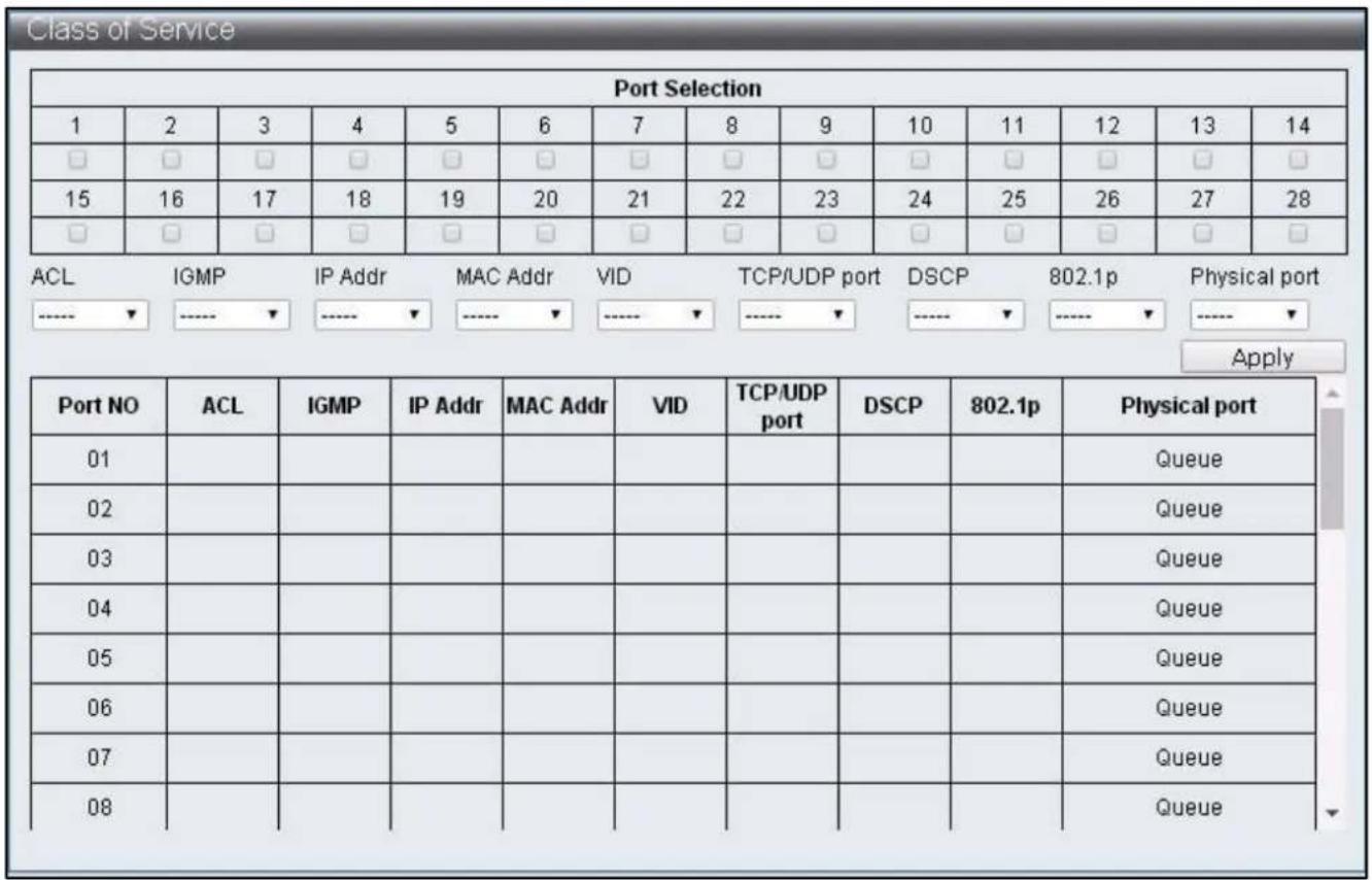
text_image
Class of Service Port Selection 1 2 3 4 5 6 7 8 9 10 11 12 13 14 □ □ □ □ □ □ □ □ □ □ □ □ □ □ 15 16 17 18 19 20 21 22 23 24 25 26 27 28 □ □ □ □ □ □ □ □ □ □ □ □ □ □ ACL IHMP IP Addr MAC Addr VID TCP/UDP port DSCP 802.1p Physical port ---- ▼ ---- ▼ ---- ▼ ---- ▼ ---- ▼ ---- ▼ ---- ▼ Apply Port NO ACL IGMP.IP Addr MAC Addr VID TCP/UDP port DSCP 802.1p Physical port 01 02 03 04 05 06 07 08 Queue Queue Queue QueueFigure 44 – QoS Conguraon > Class of Service
Class of Service Priority Level:
ACL > IGMP > IP Addr > MAC Addr > VID > TCP/UDP Port > DSCP > 802.1p > Physical Port
| Item | Descripon |
| Port Selecon | Select the Ports enabled with specic packets priority by default |
| ACL | Enable / Disable ACL priority |
| IGMP | Enable / Disable IGMP priority |
| IP Addr | Enable / Disable IP Adrr (Port-MAC-IP Entry) priority |
| MAC Addr | Enable / Disable MAC Addr (LUT Priority) priority |
| VID | Enable / Disable VLAN Tag priority |
| TCP/UDP Port | Enable / Disable TCP/UDP Port number priority |
| DSCP | Enable / Disable IPv4 TOS /IPv6 DSCP priority |
| 802.1q | Enable / Disable 802.1p priority |
| Physical Port | Select the priority of each Ports Q0 ~ 7 |
IV-4-6 802.1q Base
To congure and display the 802.1q Base, click QoS Conguraon > 802.1q Base
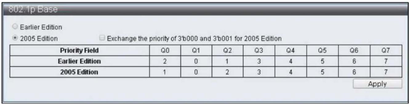
text_image
802.1p Base ○ Earlier Edition ● 2005 Edition Exchange the priority of 3'b000 and 3'b001 for 2005 Edition Priority Field Q0 Q1 Q2 Q3 Q4 Q5 Q6 Q7 Earlier Edition 2 0 1 3 4 5 6 7 2005 Edition 1 0 2 3 4 5 6 7 ApplyFigure 45 – QoS Conguraon > 802.1q Base
| Item | Descripon |
| Earlier Edion | Select earlier edion |
| 2005 Edion | Select 2005 edion |
| Exchange the priority | Edit the priority |
IV-4-7 DSCP Base
To congure and display the DSCP Base, click QoS Conguraon > DSCP Base

text_image
DSCP Base Priority For DSCP Not Match ● Regard as low priority (priority 0) ○ Ignore IP priority (priority will according to tag/port) Apply IP ToS/DSCP CoS Base Priority DSCP List Value(0-63) Priority DSCP1 Q0 Apply List Value Priority DSCP1 0 Queue7 DSCP2 0 Queue7 DSCP3 0 Queue7 DSCP4 0 Queue7 DSCP5 0 Queue7 DSCP6 0 Queue7 DSCP7 0 Queue7 DSCP8 0 Queue7Figure 46 – QoS Conguraon > DSCP Base
| Item | Descripon |
| Priority For DSCP Not Match | Select the acon when current DSCP value does not match with DSCP List |
| DSCP List | Select default DSCP group |
| Value | Specify DSCP value |
| Priority | Specify Queue matching DSCP |
IV-4-8 TCP/UDP Port Base
To congure and display the TCP/UDP Base, click QoS Conguraon > TCP/UDP Port Base

text_image
TCP/UDP Port Base TCP/UDP Port Base Priority NOTE: (1)Q0~Q7 options are effective for the selected physical port only. (2)"Drop" option is the global setting for all physical ports. (3)"BOOTP/DHCP" is not effective when DHCP relay agent enabled. Protocol Priority Protocol Priority Protocol Priority Protocol Priority FTP Q0▼ SSH Q0▼ TELNET Q0▼ SMTP Q0▼ DNS Q0▼ BOOTP/DHCP Q0▼ TFTP Q0▼得以HTTP_0,1 Q0▼ POP3 Q0▼ NEWS Q0▼ SNTP Q0▼得以NETBIOS_0,1,2 Q0▼ IMAP_0,1 Q0▼ SNMP_0,1 Q0▼得以HTTPS Q0▼得以User defined A Q0▼ User defined B Q0▼ User defined C Q0▼ User defined D Q0▼ User Define TCP/UDP Port Number NOTE: These user-defined TCP/UDP port are the same as that used in TCP/UDP filter. User defined A User defined B User defined C User defined D Port:1 Port:1 From Port:1 From Port:1 To Port:1 To Port:1 ApplyFigure 47 – QoS Conguraon > TCP/UDP Base
| Item | Descripon |
| Protocol | Each TCP/UDP protocol |
| Priority | The Queue corresponding to TCP/UDP protocol |
| User dened A | User dened TCP/UDP Port number |
| User dened B | User dened TCP/UDP Port number |
| User dened C | User dened TCP/UDP Port Range |
| User dened D | User dened TCP/UDP Port Range |
IV-5 ACL Conguraon
This switch provides 128 groups of Entries that can set up rules freely. Then according to the complexity of rules set up, a rule may occupy mulple Entries.
ACL Prole List, ACL Ctag Sengs, ACL Stag Sengs, ACL VLAN Sengs, ACL Bandwidth Sengs, ACL DSCP Sengs
IV-5-1 ACL Prole List
To congure and display the ACL Prole List, click ACL Conguraon > ACL Prole List

text_image
ACL Profile List Used Entries : 0 / 128 Profile Name Type MAC Add Profile Name Type ActionFigure 48 – ACL Conguraon > ACL Prole List
| Item | Default | Descripon |
| Used Entries | 0/128 | Displays the number of entry used by successfully congured rule, the maximum is 128. One rule does not used by one entry, the number of entries used by one rule is calculated automacally according to the conguraons |
| Prole Name | Name of the rules | |
| Type | Provide types that congured by users: MAC, IP, IP_Ext, IPv6, Advanced |
The rules set up page can be entered according to following steps:
Step1 : Enter Prole Name, select Type and press "Add" buon.
Step2 : Click "Edit" buon to edit rules.
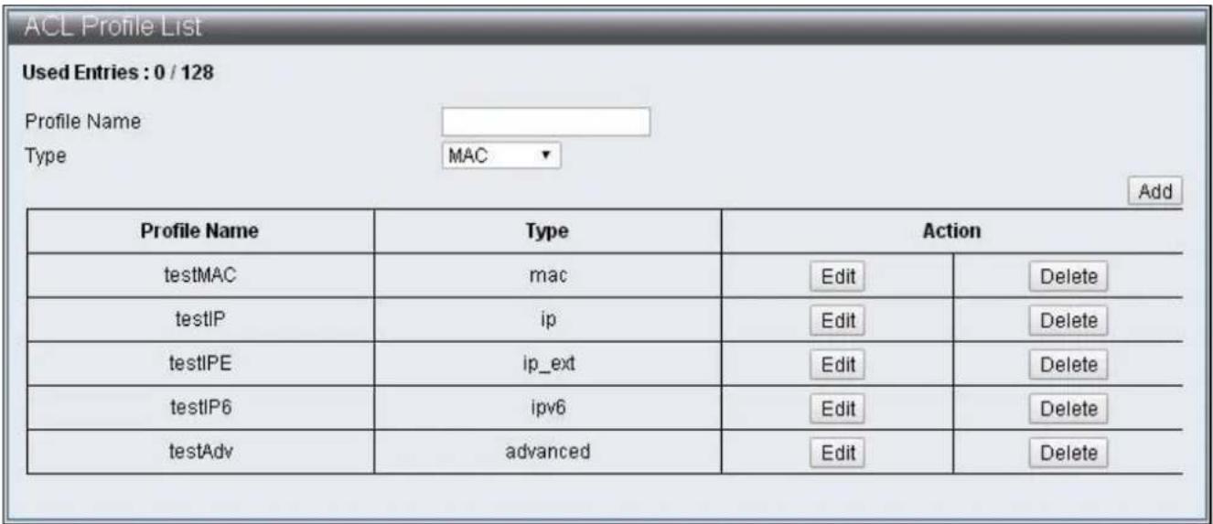
text_image
ACL Profile List Used Entries : 0 / 128 Profile Name Type MAC Add Profile Name Type Action testMAC mac Edit Delete testIP ip Edit Delete testIPE ip_ext Edit Delete testIP6 ipv6 Edit Delete testAdv advanced Edit DeleteFigure 49 – ACL Conguraon > ACL Prole List
text_image
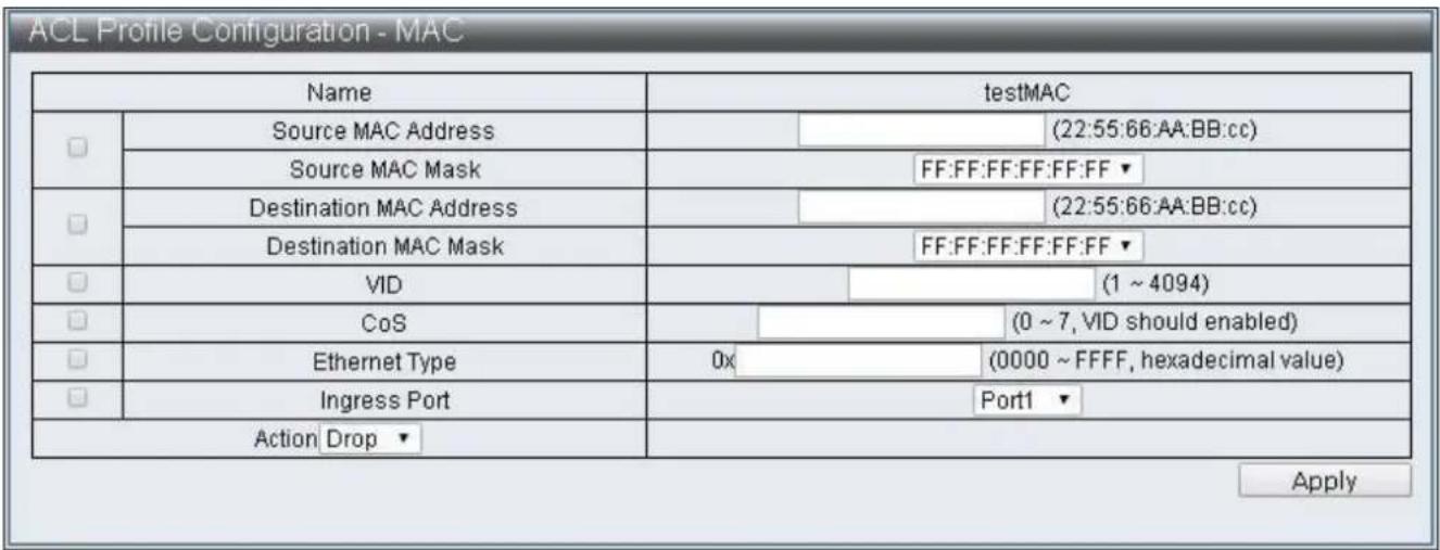
ACL Profile Configuration - MAC Name testMAC Source MAC Address (22:55:66:AA:BB:cc) Source MAC Mask FF:FF:FF:FF:FF:FF Destination MAC Address (22:55:66:AA:BB:cc) Destination MAC Mask FF:FF:FF:FF:FF:FF VID (1 ~ 4094) CoS (0 ~ 7, VID should enabled) Ethernet Type 0x (0000 ~ FFFF, hexadecimal value) Ingress Port Port1 Action Drop ApplyFigure 50 - ACL Conguraon > ACL Prole List > ACL Prole Conguraon - MAC
text_image
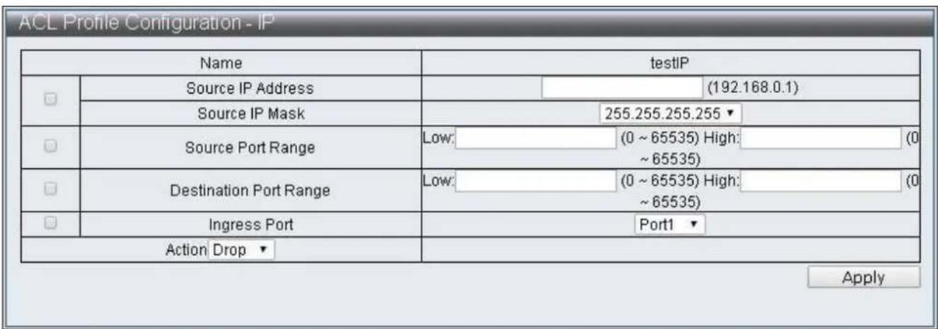
ACL Profile Configuration - IP Name testIP Source IP Address (192.168.0.1) Source IP Mask 255.255.255.255 ▼ Source Port Range Low: (0 ~ 65535) High: (0 ~ 65535) Destination Port Range Low: (0 ~ 65535) High: (0 ~ 65535) Ingress Port Port1 ▼ Action Drop ▼ ApplyFigure 51 - ACL Conguraon > ACL Prole List > ACL Prole Conguraon - IP
| Name | testIPE | |||
| ☐ | Source IP Address | (192.168.0.1) | ||
| Source IP Mask | 255.255.255.255 ▼ | |||
| ☐ | Destination IP Address | (192.168.0.1) | ||
| Destination IP Mask | 255.255.255.255 ▼ | |||
| ☐ | Source Port | ○ | (0 ~ 65535) | |
| ○ Low: | (0 ~ 65535) High: | |||
| (0 ~ 65535) | ||||
| ☐ | Destination Port | ○ | (0 ~ 65535) | |
| ○ Low: | (0 ~ 65535) High: | |||
| (0 ~ 65535) | ||||
| ☐ | VID | (1 ~ 4094) | ||
| ☐ | CoS | (0 ~ 7, VID should enabled) | ||
| ☐ | TCP Flag | URG ACK PSH RST SYN FIN | ||
| ☐ | DSCP | (0 ~ 63) | ||
| ☐ | IP Protocol | 0x | (00 ~ FF) | |
| ☐ | Ingress Port | Port1 ▼ | ||
| Action Drop ▼ | ||||
Figure 52 - ACL Conguraon > ACL Prole List > ACL Prole Conguraon – IP Extension
text_image
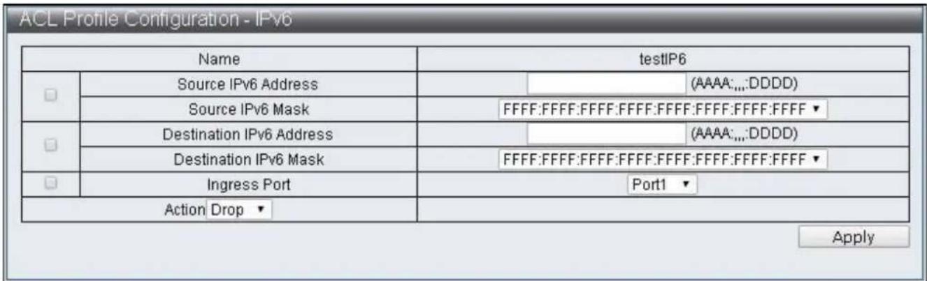
ACL Profile Configuration - IPv6 Name testIP6 Source IPv6 Address (AAAA:.,;DDDD) Source IPv6 Mask FFFF:FFFF:FFFF:FFFF:FFFF:FFFF:FFFF ▼ Destination IPv6 Address (AAAA:.,;DDDD) Destination IPv6 Mask FFFF:FFFF:FFFF:FFFF:FFFF:FFFF:FFFF ▼ Ingress Port Port1 ▼ Action Drop ▼ ApplyFigure 53 - ACL Conguraon > ACL Prole List > ACL Prole Conguraon - IPv6

text_image
ACL Profile Configuration - Advanced Name testAdv Source MAC Address (22:55:66:AA:BB:cc) Source MAC Mask FF:FF:FF:FF:FF:FF ▼ Destination MAC Address (22:55:66:AA:BB:cc) Destination MAC Mask FF:FF:FF:FF:FF:FF ▼ Source IP Address (192.168.0.1) Source IP Mask 255.255.255.255 ▼ Destination IP Address (192.168.0.1) Destination IP Mask 255.255.255.255 ▼ Source Port (0 ~ 65535) Low: (0 ~ 65535) High: (0 ~ 65535) Destination Port (0 ~ 65535) Low: (0 ~ 65535) High: (0 ~ 65535) VID (1 ~ 4094) CoS (0 ~ 7, VID should enabled) Ethernet Type 0x (0000 ~ FFFF, hexadecimal value) TCP Flag URG ACK PSH RST SYN FIN DSCP (0 ~ 63) IP Protocol 0x (00 ~ FF) Ingress Port Port1 ▼ Action Drop ▼ ApplyFigure 54 - ACL Conguraon > ACL Prole List > ACL Prole Conguraon - Advanced
| Item | Descripon |
| Source MAC Address | Enter Source MAC Address |
| Source MAC Mask | Select Source MAC Mask, then FF:FF:FF:FF:FF:FF,FF:FF:FF:00:00:00 and FF:FF:00:00:00:00 can be selected |
| Desnaon MAC Address | Enter Desnaon MAC Address |
| Desnaon MAC Mask | Select Desnaon MAC Mask, then FF:FF:FF:FF:FF:FF,FF:FF:FF:00:00:00 and FF:FF:00:00:00:00 can be selected |
| Source IP Address | Enter Source IP Address |
| Source IP Mask | Select Source IP Mask, then 255.255.255.255,255.255.255.240, 255.255.255.0,255.255.240.0,255.255.0.0,255.0.0.0 and 240.0.0.0 can be selected |
| Desnaon IP Address | Enter Desnaon IP Address |
| Desnaon IP Mask | Select Desnaon IP Mask, then 255.255.255.255,255.255.255.240,255.255.255.0,255.255.240.0,255.255.0.0,255.0.0.0 and 240.0.0.0 can be selected |
| Source Port | Enter Source Port, single value can be entered or a range |
| value can be congured | |
| Desnaon Port | Enter Desnaon Port, single value can be entered or a range value can be congured |
| VID | Enter VID, the conguraon range is 1~4094 |
| CoS | Congure CoS, it is eecve only with VID sengs together, the conguraon range is 0~7 |
| Ethernet Type | Enter Ethernet Type, the conguraon range is 0000~FFFF |
| TCP Flag | Select the TCP Flag to be checked |
| DSCP | Enter DSCP, the conguraon range is 0~63 |
| IP Protocol | Enter IP Protocol, the conguraon range is 00~FF |
| Source IPv6 Address | Enter Source IPv6 Address |
| Source IPv6 Mask | Select Source IPv6 Mask, FFFF:FFFF:FFFF:FFFF:FFFF:FFFF:FFFF:FFFF:FFFF:FFFF:FFFF:FFFF:0000:0000, FFFF:FFFF:FFFF:FFFF:0000:0000:0000:0000 and FFFF:0000:0000:0000:0000:0000:0000:0000 can be selected |
| Desnaon IPv6 Address | Enter Desnaon IPv6 Address |
| Desnaon IPv6 Mask | Select Desnaon IPv6 Mask, FFFF:FFFF:FFFF:FFFF:FFFF:FFFF:FFFF:FFFF:FFFF:FFFF:FFFF:FFFF:FFFF:FFFF:FFFF:FFFF:FFFF:FFFF:FFFF:FFFF:FFFF:FFFF:FFFF:FFFF:FFFF:FFFF:FFFF:FFFF:FFFF:FFFF:FFFF:FFFF:FFFF:FFFF:FFFF:FFFF:FFFF:FFFF:FFFF:FFFF:FFFF:FFFF:FFFF:FFFF:FFFF:FFFF:FFFF:FFFF:FFFF:FFFF:FFFF: |
| Ingress Port | Select source Port |
Acon Drop
| Action Drop ▼ |
Acon Type1
| Action Type1 ▼ | ☐ | Redirect | Port 1 ▼ | ||
| ☐ | Priority | (0 ~ 7) | |||
| ☐ | DSCP | (1 ~ 8, index select) | |||
| ☐ | Copy to CPU | ||||
| ☐ | Mirror Enable | ||||
Acon Type2
| Action Type2 ▼ | Redirect | Port 1 ▼ | ||||
| Priority | (0 ~ 7) | |||||
| Bandwidth | (1 ~ 15, index select) | |||||
| Copy to CPU | ||||||
| PTP Enable | ||||||
| Sflow Enable | ||||||
Acon Type3
| Action Type3 ▼ | Redirect | Port 1 ▼ | ||||
| Priority | (0 ~ 7) | |||||
| Insert Ctag | (1 ~ 24, index select) | |||||
| Ctag Vlan Enable | ||||||
Acon Type4
| Action Type4 ▼ | Insert Ctag | (1 ~ 24, index select) | |||
| Ctag Vlan Enable | |||||
| Insert Stag | (1 ~ 24, index select) | ||||
| Stag Vlan Enable | |||||
| Mirror Enable | |||||
| Item | Descripon |
| Redirect | Specify to redirect to a Port |
| Priority | Specify Priority, the conguraon range is 0~7 |
| DSCP | Specify DSCP Index, edit the sent DSCP according to ACL DSCP Sengs |
| Bandwidth | Specify Bandwidth Index according to the value congured by ACL Bandwidth Sengs to restrict the packets trac |
| Copy to CPU | Made a copy and send to CPU |
| PTP Enable | Specify the me when packets records is enabled |
| Mirror Enable | Enable Mirror funcon, then transmit packets to Desnaon Port according to the conguraon of Basic Conguraon->Port Mirror Funcon |
| Sow Enable | Specify to enable the Sow funcon |
| Insert Ctag | Specify Insert Ctag Index, then insert corresponding Ctag according to ACL Ctag Sengs |
| Ctag Vlan Enable | Enable the funcon of selecng ACL VLAN Sengs to transmit packets according Insert Ctag Index |
| Insert Stag | Specify Insert Stag Index, then insert corresponding Ctag value according to ACL Stag Sengs |
| Stag Vlan Enable | Enable the funcon of selecng ACL VLAN Sengs to transmit packets according to Insert Stag Index |
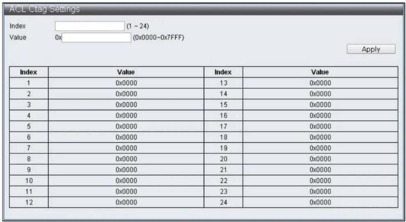
IV-5-2 ACL Ctag Sengs
To congure and display the ACL Ctag Sengs, click ACL Conguraon > ACL Ctag Sengs
text_image
ACL Ctag Settings Index (1 ~ 24) Value 0x (0x0000~0x7FFF) Apply Index Value Index Value 1 0x0000 13 0x0000 2 0x0000 14 0x0000 3 0x0000 15 0x0000 4 0x0000 16 0x0000 5 0x0000 17 0x0000 6 0x0000 18 0x0000 7 0x0000 19 0x0000 8 0x0000 20 0x0000 9 0x0000 21 0x0000 10 0x0000 22 0x0000 11 0x0000 23 0x0000 12 0x0000 24 0x0000Figure 55 - ACL Conguraon > ACL Ctag Sengs

text_image
ACL Stag Settings Index (1 ~ 24) Value 0x (0x0000~0xFFFF) Apply Index Value/Index Value 1 0x0000 13 0x0000 2 0x0000 14 0x0000 3 0x0000 15 0x0000 4 0x0000 16 0x0000 5 0x0000 17 0x0000 6 0x0000 18 0x0000 7 0x0000 19 0x0000 8 0x0000 20 0x0000 9 0x0000 21 0x0000 10 0x0000 22 0x0000 11 0x0000 23 0x0000 12 0x0000 24 0x0000Figure 56 - ACL Conguraon > ACL Stag Sengs

text_image
ACL VLAN Settings Index 1 ▼ Member Port 1 2 3 4 5 6 7 8 9 10 11 12 13 14 □ □ □ □ □ □ □ □ □ □ □ □ □ □ 15 16 17 18 19 20 21 22 23 24 25 26 27 28 □ □ □ □ □ □ □ □ □ □ □ □ □ □ Apply Index Member Port/Index Member Port 1 2 3 4 5 6 7 8 9 10 11 12 13 14 15 16 17 18 19 20 21 22 23 24Figure 57 - ACL Conguraon > ACL VLAN Sengs
text_image
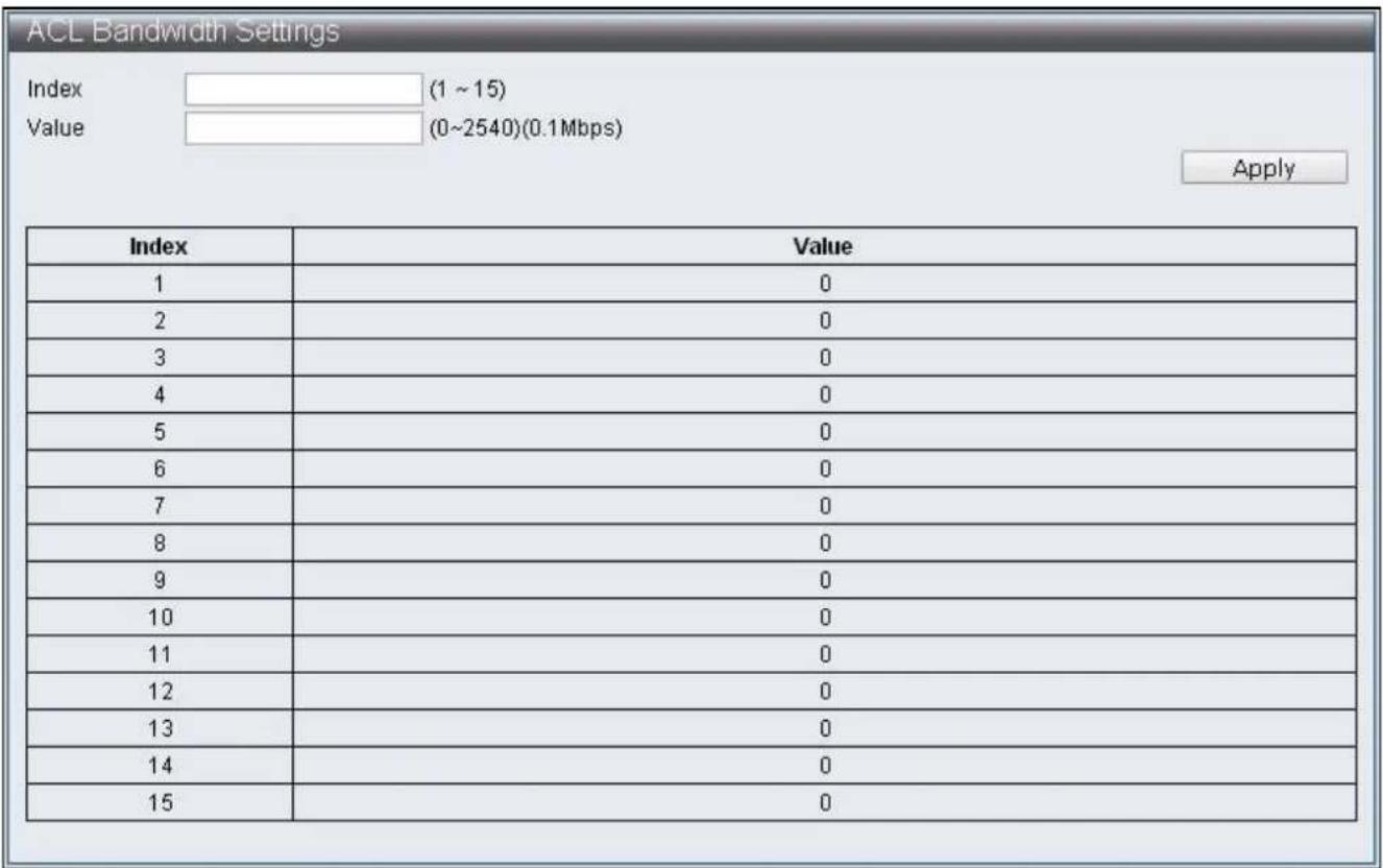
ACL Bandwidth Settings Index (1 ~ 15) Value (0~2540)(0.1Mbps) Apply Index Value 1 0 2 0 3 0 4 0 5 0 6 0 7 0 8 0 9 0 10 0 11 0 12 0 13 0 14 0 15 0Figure 58 - ACL Conguraon > ACL Bandwidth Sengs
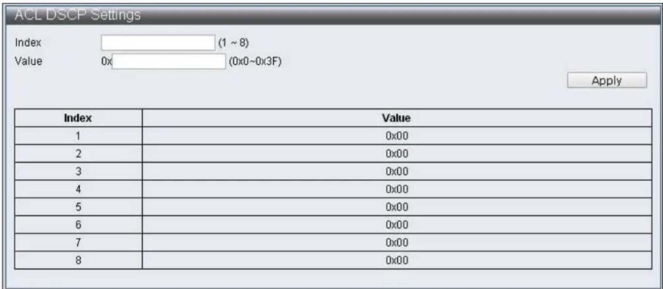
To congure and display the ACL DSCP Sengs, click ACL Conguraon > ACL DSCP Sengs
text_image
ACL DSCP Settings Index (1 ~ 8) Value 0x (0x0~0x3F) Apply Index Value 1 0x00 2 0x00 3 0x00 4 0x00 5 0x00 6 0x00 7 0x00 8 0x00Figure 59 - ACL Conguraon > ACL DSCP Sengs
IV-6 Security
IV-6-1 Port-MAC-IP Binding
Supporting IPv4/IPv6 to achieve basic security protecon and iterating through checking the source IP address of packets. Congure each port through page to check if source IP address, MAC address and source port are compatible, then perform further acon on matched packets through the two iterating modes.
IV-6-1-1 Port-MAC-IP Port Sengs
To congregate and display the Port - MAC - IP Port Sengs, click Security > Port - MAC - IP Binding > Port - MAC - IP Port Sengs
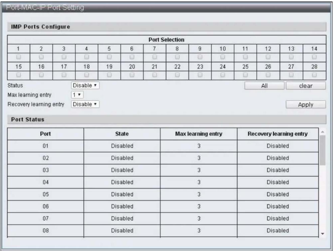
text_image
Port-MAC-IP Port Setting IMP Ports Configure Port Selection 1 2 3 4 5 6 7 8 9 10 11 12 13 14 □ □ □ □ □ □ □ □ □ □ □ □ □ □ 15 16 17 18 19 20 21 22 23 24 25 26 27 28 □ □ □ □ □ □ □ □ □ □ □ □ □ □ Status Disable All clear Max learning entry 1▼ Recovery learning entry Disable Apply Port Status Port State Max learning entry Recovery learning entry 01 Disabled 3 Disabled 02 Disabled 3 Disabled 03 Disabled 3 Disabled 04 Disabled 3 Disabled 05 Disabled 3 Disabled 06 Disabled 3 Disabled 07 Disabled 3 Disabled 08 Disabled 3 DisabledFigure 60 - Security > Port - MAC - IP Binding > Port - MAC - IP Port Seng
| Item | Descripon |
| Port Selecon | Select sengs Ports |
| All | Select all Ports |
| Clear | Remove all Ports |
| Status | Enable / Disable Port-MAC-IP binding funcon |
| Max learning entry | Specify the maximum groups of dynamic binding of each Port |
| Recover learning entry | Enable / Disable the automac coverage of the earliest binding group when the dynamic binding groups reach the upper limit |
IV-6-1-2 Port-MAC-IP Entry Seng
To congure and display the Port - MAC - IP Entry Seing, click Security > Port - MAC - IP Binding > Port - MAC - IP Entry Sengs

text_image
Port-MAC-IP Table Create IMP Entry IPv4 ▼ Apply IMP Entry Management IP check port □ Port 1 ▼ check MAC □ MAC Action Priority ▼ Priority Disable ▼ Apply IP Table Monitor IP Type port MAC Rule Priority Action 192.168.2.10 static □ 0 □ filterpass日起 编辑 编辑 Edit DeleteFigure 61 - Security > Port - MAC - IP Binding > Port - MAC - IP Entry Seng
| Item | Descripon |
| IPv4/IPv6 | Select the default IMP Entry as IPv4 or IPv6, then enter its IP Address in the blank cell on the right |
| IMP Entry Management | Select the IMP Entry to be edited in IP Table Monitor, then click Edit for edit |
| IP | Match the selected IMP Entry IP Address |
| Check port | Enable / Disable if source Port is matched |
| Port | Specify the Port matched with this IP Address |
| Check MAC | Enable / Disable if MAC is matched |
| MAC | Specify the source MAC matched with IP Address |
| Acon | Specify the matching Filter/Priority when the terms are complied with |
| Priority | Specify that when Priority is enabled, the Queue matched IMP Entry |
IV-6-1-3 DHCP Snooping Entry Seng
To congregate and display the DHCP Snooping Entry Seing, click Security > Port - MAC - IP Binding > DHCP Snooping Entry Seng

text_image
DHCP Snooping Table DHCP Snooping Configure DHCP Snooping Disable ▼ ARP Inspection Disable ▼ MAC Verification Disable ▼ Apply Snooping Table Port IP MAC Leavetime ActionFigure 62 - Security > Port - MAC - IP Binding > DHCP Snooping Entry Seng
| Item | Descripon |
| DHCP Snooping | Enable / Disable DHCP Snooping |
| ARP Inspecon | Enable / Disable ARP Inspecon |
| MAC Vericaon | Enable / Disable MAC Vericaon |
IV-6-2 MAC Address Binding
To enable the security funcon of MAC address, packets that don't match with MAC address table should be congured to be discarded or ports are congured to discard certain MAC address, port mirroring and sampling transmied to CPU port. MAC address not included in the MAC address table can only be eecvely prevented from entering the switch from its binding port when the port learning funcon is disabled. When the port learning is enabled, MAC address included in the MAC address table can enter the switch from its binding port, but MAC address not in the MAC address table cannot be limited from entering the switch from any port.
To congure and display the MAC Address Binding, click Security > MAC Address Binding
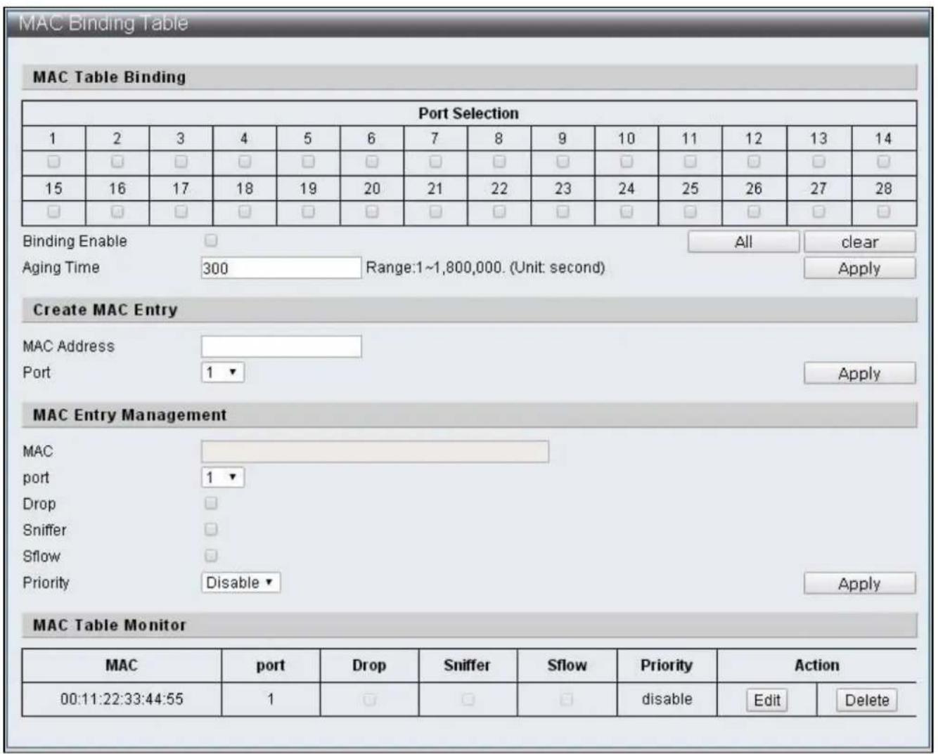
text_image
MAC Binding Table MAC Table Binding Port Selection 1 2 3 4 5 6 7 8 9 10 11 12 13 14 □ □ □ □ □ □ □ □ □ □ □ □ □ □ 15 16 17 18 19 20 21 22 23 24 25 26 27 28 □ □ □ □ □ □ □ □ □ □ □ □ □ □ Binding Enable Aging Time All-clear 300 Range:1~1,800,000. (Unit: second) Apply Create MAC Entry MAC Address Port 1 ▼ Apply MAC Entry Management MAC port 1 ▼ Drop Sniffer Sflow Priority Disable ▼ Apply MAC Table Monitor MAC port Drop Sniffer Sflow Priority Action 00:11:22:33:44:55 1 □ □ □ Ratingsquare Edit DeleteFigure 63 - Security > MAC Address Binding
| Item | Descripon |
| Port Selecon | Select to disable port learning funcon |
| Binding Enable | Enable / Disable MAC binding |
| Aging Time | Specify the aging me range of MAC address binding from 1~1800000, unit: second |
| MAC Address | Add default MAC Address binding |
| Port | Select the Port binding MAC Address |
| MAC Entry Management | Aer adding the binding MAC Address, select MAC address in the Table, click Edit to edit the content. Click Delete to remove the seng of that record |
| MAC | Display the default MAC Address |
| port | Edit the Port binding MAC Address |
| Drop | When the Source MAC of packets received by Port match with the seng, drop such packets |
| Snier1 | When the Source MAC of packets received by Port match with the seng, forward such packets to the Desnaon Port of Port Mirror. |
| Sow | Sampling transmits the matched packets to CPU ports |
| Priority | When the Source MAC of packets received by Port match with the seng, save such packets into corresponding Queue |
IV-7 Advanced Features
IV-7-1 Spanning Tree Protocol STP
Spanning Tree Protocol (STP) is a network protocol based on the data link layer (second layer) of OSI model. It aims to build a loop-free logical topology for Ethernet networks. STP prevents bridge loops and allows a network design to include backup (repeve) links to automacally acvate back up path if an acve link fails. Manual acvaon is disabled and closes the demands of backup conncon. Thus, STP has three funcons including: 1. Prevents broadcast storm, 2. Prevents duplicate packets, 3. Prevents MAC address table trashing.
The STP work process is as follows: the rst step is to elect a root bridge, then follow by the bridge ID generated by combining bridge priority and MAC address. The network bridge with smallest bridge ID will be the root bridge. Based on this, calculate the distances from each node to the root bridge, then nd the cost of redundant links. The smallest path cost will be the communicang path (the corresponding port state will become “forwarding”), others will be the backup paths (the corresponding port state will become “blocking”). The communicaon tasks will be completed by BPDU (Bridge Protocol Data Unit) during STP process.
BPDU
Bridge Protocol Data Unit (BPDU) is spanning tree protocol packets that send during congured intervals and used in informaon exchange during network bridges.
Region (applicable to MSTP)
Switch in the same Region will only process BPDU from the same region to calculate Topology. To check if it is in the same region, Switch will compare the three items of spanning-tree mst conguraon, these three items have to be the same to be seen as the same Region.
Conguraon Name Revision Number
VLAN and Instance map (instance 0 is CIST and communicate with STP/RSTP but cannot be used for Region)
IV-7-1-1 STP Global Sengs
To congure and display the STP Global Sengs, click Advanced Features > Spanning Tree Protocol > STP Global Sengs
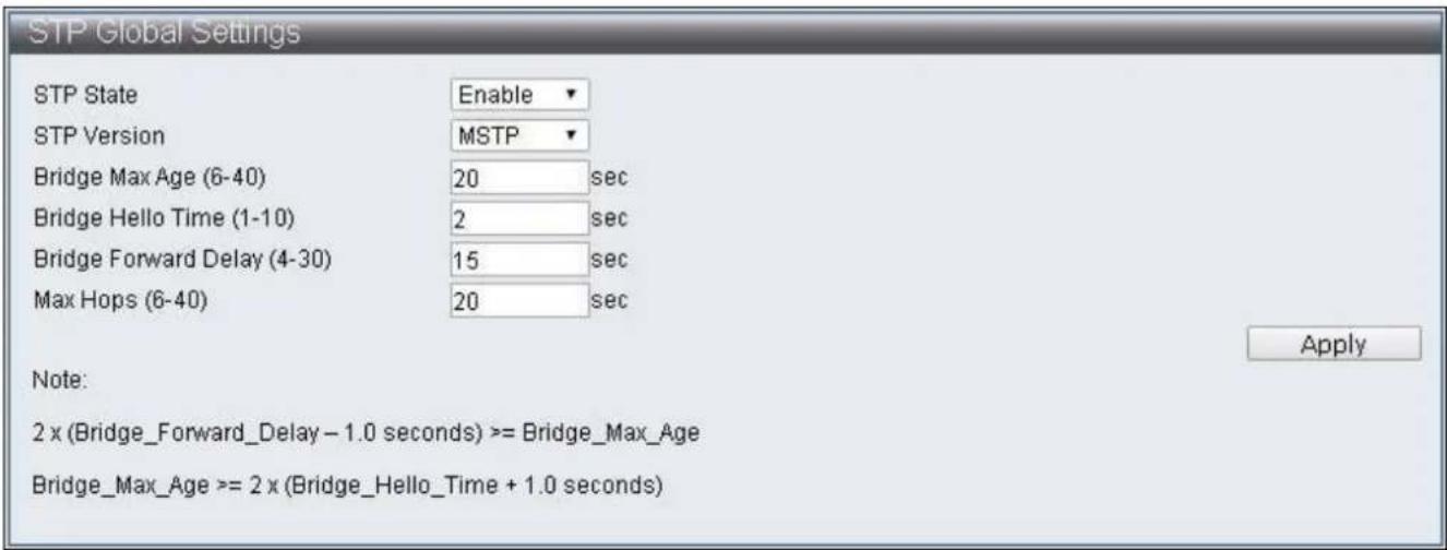
text_image
STP Global Settings STP State Enable STP Version MSTP Bridge Max Age (6-40) 20 sec Bridge Hello Time (1-10) 2 sec Bridge Forward Delay (4-30) 15 sec Max Hops (6-40) 20 sec Apply Note: 2 x (Bridge_Forward_Delay - 1.0 seconds) >= Bridge_Max_Age Bridge_Max_Age >= 2 x (Bridge_Hello_Time + 1.0 seconds)Figure 64 - Advanced Features > Spanning Tree Protocol > STP Global Sengs
| Item | Default | Descripon |
| STP State | Enable | Enable / Disable STP state |
| STP Version | MSTP | Specify the STP versions used and supports STP,RSTP,MSTP |
| Bridge Max Age (6-40) | 20 | Specify the maximum age of conguraon whenthis Switch is a Root Bridge, if any Bridge Port(excluding Designated Port ) of spanning tree protodid not receive BPDU within this period, such BridgePort will start sending BPDU and build anotherspanning tree protocol |
| Bridge Hello Time(1-10) | 2 | The interval of each bridge in the STP sending BPDUwhen Switch is Root Bridge |
| Bridge Forward Delay(4-30) | 15 | Specify the me interval for all switch portconverng to Forwarding when this Switch is theRoot Bridge |
| Max Hops (6-40) | 20 | Specify the starng value of Remaining Hops whenMSTP mode is on, and the switch is the Root Bridge.This value limit the maximum nodes BPDU cansend. Every Switch will reduce the Remaining Hopsby 1 aer receiving BPDU, and no more BPDU willbe sent to the when the value reach 0. |
IV-7-1-2 STP Port Sengs
To congure and display the STP Port Sengs, click Advanced Features > Spanning Tree Protocol > STP Port Sengs

text_image
STP Port Settings STP Port Enabled 1 2 3 4 5 6 7 8 9 10 11 12 13 14 ✓ ✓ ✓ ✓ ✓ ✓ ✓ ✓ ✓ ✓ ✓ ✓ ✓ ✓ 15 16 17 18 19 20 21 22 23 24 25 26 27 28 ✓ ✓ ✓ ✓ ✓ ✓ ✓ ✓ ✓ ✓ ✓ ✓ ✓ ✓ ApplyFigure 65 – Advanced Features > Spanning Tree Protocol > STP Port Sengs
| Item | Default | Descripon |
| STP Port Enabled | Enabled | Select STP enabled Port |
IV-7-1-3 MST Conguraon Idencaon
To congure and display the MST Conguraon Idencaon, click Advanced Features > Spanning Tree Protocol > MST Conguraon Idencaon
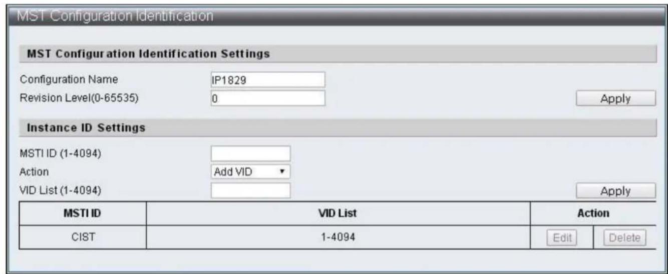
text_image
MST Configuration Identification MST Configuration Identification Settings Configuration Name IP1829 Revision Level(0-65535) 0 Apply Instance ID Settings MSTI ID (1-4094) Action Add VID VID List (1-4094) Apply MSTI ID VID List Illustration CIST 1-4094 Edit DeleteFigure 66 – Advanced Features > Spanning Tree Protocol > MST Conguraon Idencaon
| Item | Default | Descripon |
| Conguraon Name | IP1829 | Specify the name of conguraon, it is the only idencaon of MSTI (Mulple Spanning TreeInstance) |
| Revision Level(0-65535) | 0 | Specify version numbers to recognize if it is the same MSTP region |
| MSTI ID (1-4094) | The ID code of MSTI entry to be specied | |
| Acon | Add VID | The VID List methods of MSTI to be speciedAdd VID: Add VID List to this MSTIRemove VID: Remove VID List from this MSTI |
| VID List (1-4094) | The VID List contents of MSTI to be changed |
IV-7-1-4 STP Instance Sengs
To congure and display the STP Instance Sengs, click Advanced Features > Spanning Tree Protocol > STP Instance Sengs
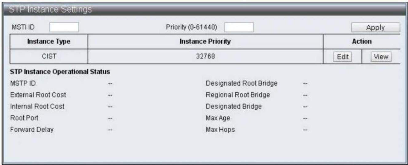
text_image
STP Instance Settings MSTI ID Priority (0-61440) Apply Instance Type Instance Priority Action CIST 32768 Edit View STP Instance Operational Status MSTP ID -- Designated Root Bridge -- External Root Cost -- Regional Root Bridge -- Internal Root Cost -- Designated Bridge -- Root Port -- Max Age -- Forward Delay -- Max Hops --Figure 67 – Advanced Features > Spanning Tree Protocol > STP Instance Sengs
IV-7-1-5 MSTP Port Informaon
To congregate and display the MSTP Port Informaon, click Advanced Features > Spanning Tree Protocol > MSTP Port Informaon
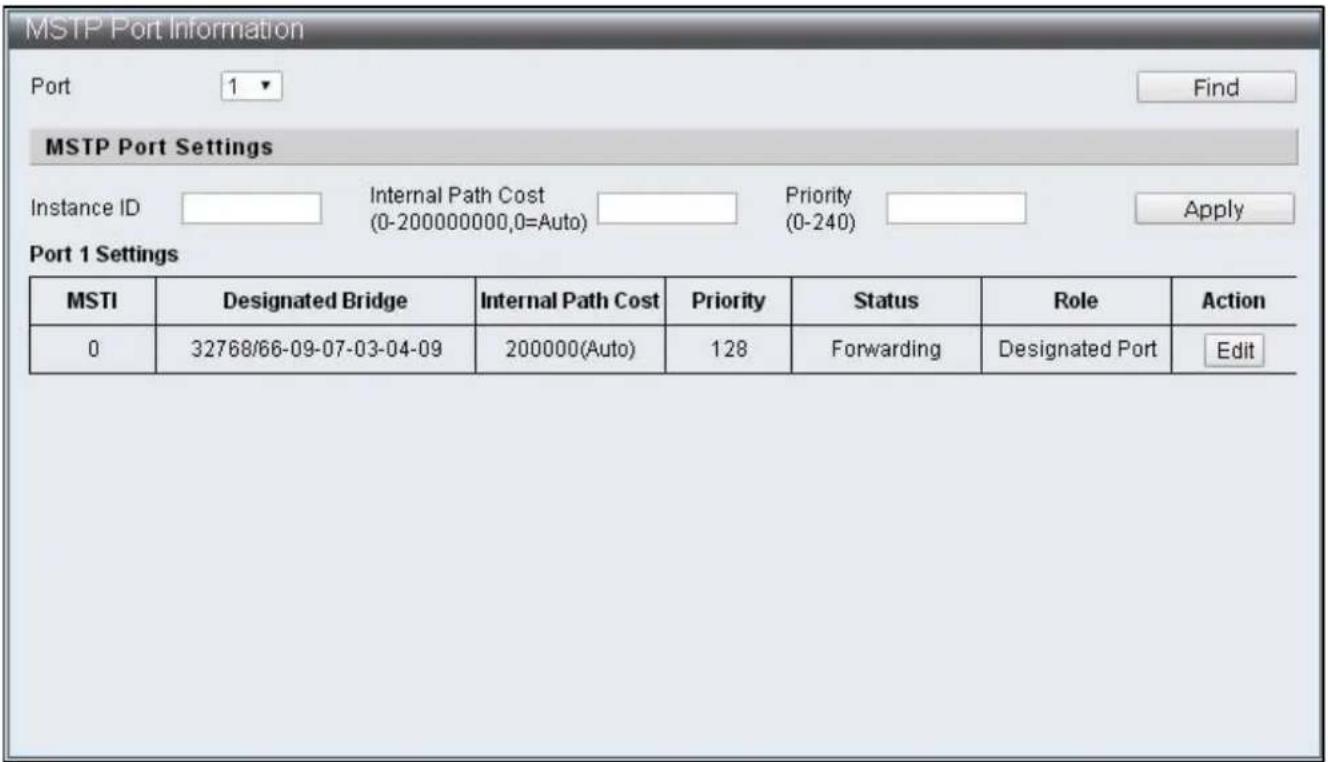
text_image
MSTP Port Information Port 1 Find MSTP Port Settings Instance ID Internal Path Cost Priority Apply (0-200000000,0=Auto) (0-240) Port 1 Settings MSTI Designated Bridge Internal Path Cost Priority Status Role Action 0 32768/66-09-07-03-04-09 200000(Auto) 128 Forwarding Designated Port EditFigure 68 – Advanced Features > Spanning Tree Protocol > MSTP Port Informaon
| Item | Default | Descripon |
| Port | 1 | The displaying and specied Port number |
| Instance ID | The ID number that needs to be specied with MSTI entry | |
| Internal Path Cost(0-200000000,0=Auto) | Specify the internal path cost of this Port in MSTI and treat this Region as an independent LAN, this value refers to the root path cost from bridge to the root of this network. | |
| Priority (0-240) | Specied the priority of this Port in that MSTI |
IV-7-2 Trunk & Link Aggregaon
Trunk Groups are manually-congured aggregate links containing mulple ports to reach faster network speed using specific trac management. ES-5424P supports trunk group of four 10/100MB and trunk group of two 1G. There are four stac ports can be selected as member in each 10/100MB trunk group, and there are two stac ports can be selected as member in each 1G trunk group. By combing two groups, then as much as eight 10/100MB members can be formed as a trunk group and join with another trunk group of four 1G members.
To congure and display the Trunk & Link Aggregaon, click Advanced Features > Spanning Tree Protocol > Trunk & Link Aggregaon
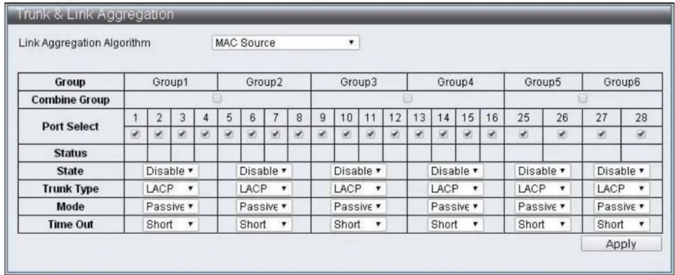
text_image
Trunk & Link Aggregation Link Aggregation Algorithm MAC Source Group Group1 Group2 Group3 Group4 Group5 Group6 Combine Group Port Select 1 2 3 4 5 6 7 8 9 10 11 12 13 14 15 16 25 26 27 28 ✓ ✓ ✓ ✓ ✓ ✓ ✓ ✓ ✓ ✓ ✓ ✓ ✓ ✓ ✓ ✓ ✓ ✓ ✓ ✓ ✓ ✓ ✓ ✓ ✓ ✓ ✓ ✓ ✓ ✓ ✓ ✓ ✓ ✓ ✓ ✓ ✓ ✓ ✓ ✓ ✓ ✓ ✓ ✓ ✓ ✓ ✓ ✓ ✓ ✓ ✓ ✓ ✓ ✓ ✓ ✓ ✓ ✓ ✓ ✓ ✓ ✓ ✓ ✓ ✓ ✓ ✓ ✓ ✓ ✓ ✓ ✓ ✓ ✓ ✓ ✓ ✓ ✓ ✓ ✓ ✓ ✓ ✓ ✓ ✓ ✓ ✓ ✓ ✓ ✓ ✓ ✓ ✓ ✓ ✓ ✓ ✓ ✓ ✓ ✓ ✓ Status State Disable Trunk Type LACP Mode Passive Time Out Short Disable LACP Passive Passive Short Disable LACP Passive Short Disable LACP Passive Short ApplyFigure 69 – Advanced Features > Spanning Tree Protocol > MSTP Port Informaon
| Item | Default | Descripon |
| Link Aggregaon Algorithm | MAC Source | Link Aggregaon algorithm supports Port, MAC Source, MAC Desnaon, IP Source, IP Desnaon, TCP/UDP Desnaon Port, TCP/UDP Source Port |
| Group | Group directory | |
| Combine Group | Combine two groups | |
| Port Select | Select group members | |
| Status | Displays member status, “A” indicates that funcon set up has been completed | |
| State | Disable | Enable / Disable group |
| Trunk Type | LACP | Selecon of Trunk type and supports LACP and Stac |
| Mode | Passive | Communicaon mode supports Passive and Acve |
| Time Out | Short | The length of Time Out, which include Short and Long. Short refers to that packets are sent every second, the Time Out is 3 seconds. Long refers to that packets are sent every 30 seconds, the Time Out is 90 seconds |
IV-7-3 IGMP Snooping
Internet Group Management Protocol (IGMP) Snooping IGMP Snooping Sengs IGMP Snooping Router Ports Sengs IGMP Snooping Groups IGMP Snooping Ports
IV-7-3-1 IGMP Snooping Sengs
To congure and display the IGMP Snooping Sengs, click Advanced Features > IGMP Snooping > IGMP Snooping Sengs

text_image
IGMP Snooping Settings IGMP Snooping State Disable Version IGMPv3 IGMP Group Aged Out Disable GMI (10-65535) 100 sec Router Aging Time (10-65535) 100 sec ApplyFigure 70 – Advanced Features > IGMP Snooping > IGMP Snooping Seings
| Item | Default | Descripon |
| IGMP Snooping State | Disable | Enable / Disable IGMP Snooping |
| Version | IGMPv3 | Version selecons, IGMPv1,IGMPv2 and IGMPv3 can be selected |
| IGMP Group Aged Out | Disable | The dynamically added Group should be removed without receiving corresponding packets aer a period me as specied in the GMI below |
| GMI | 100(seconds) | Group Member Interval, dynamic Group will inquire if there is existence of member aer specicaon |
| Router Aging Time | 100(seconds) | Group Member Interval, dynamic Group will inquire if there is existence of member aer specicaon |
IV-7-3-2 IGMP Snooping Router Ports Sengs
To congregate and display the IGMP Snooping Router Ports Sengs, click Advanced Features > IGMP Snooping > IGMP Snooping Router Ports Sengs
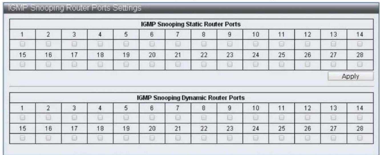
Figure 71 – Advanced Features > IGMP Snooping > IGMP Snooping Router Ports Sengs
| Item | Descripon |
| IGMP Snooping Stac Router Ports | Stac Router Ports can be specied |
| IGMP Snooping Dynamic Router Ports | Displays dynamic learning Router Ports |
IV-7-3-3 IGMP Snooping Groups
To congure and display the IGMP Snooping Groups, click Advanced Features > IGMP Snooping > IGMP Snooping Groups
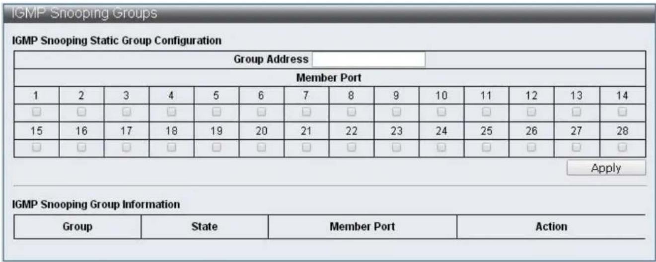
text_image
IGMP Snooping Groups IGMP Snooping Static Group Configuration Group Address Member Port 1 2 3 4 5 6 7 8 9 10 11 12 13 14 □ □ □ □ □ □ □ □ □ □ □ □ □ □ 15 16 17 18 19 20 21 22 23 24 25 26 27 28 □ □ □ □ □ □ □ □ □ □ □ □ □ □ Apply IGMP Snooping Group Information Group State Member Port ActionFigure 72 – Advanced Features > IGMP Snooping > IGMP Snooping Groups
| Item | Descripon |
| IGMP Snooping Stac Group Conguraon | Enable users to specify stac Group and its member port |
| IGMP Snooping Group Informaon | Displays all the currently exisng Groups and their status |
IV-7-3-4 IGMP Snooping Ports
To congure and display the IGMP Snooping Ports, click Advanced Features > IGMP Snooping > IGMP Snooping Ports
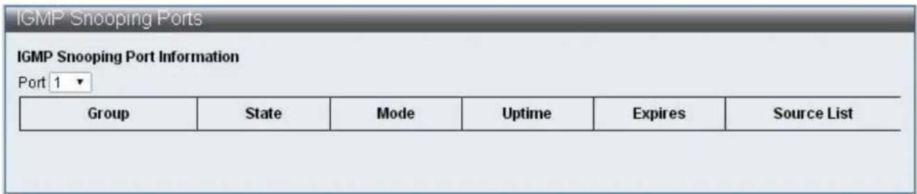
text_image
IGMP Snooping Ports IGMP Snooping Port Information Port 1 ▼ Group State Mode Uptime Expires Somc e ListFigure 73 – Advanced Features > IGMP Snooping > IGMP Snooping Ports
| Item | Descripon |
| IGMP Snooping Port Informaon | Displays the groups and their status of selected Port |
IV-7-4 MLD Snooping
MLD Snooping
Mulcast Listener Discovery (MLD) Snooping
MLD Snooping Sengs
MLD Snooping Router Ports Sengs MLD Snooping Groups
MLD Snooping Ports
IV-7-4-1 MLD Snooping Sengs
To congure and display the MLD Snooping Sengs, click Advanced Features > MLD Snooping > MLD Snooping Sengs
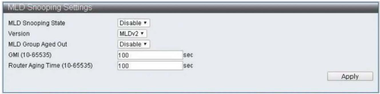
text_image
MLD Snooping Settings MLD Snooping State Version MLD Snooping State MLD Snooping State MLD Snooping State MLD Snooping State Version MLDv2 MLD Group Aged Out GMI (10-65535) 100 sec Router Aging Time (10-65535) 100 sec ApplyFigure 74 – Advanced Features > MLD Snooping > MLD Snooping Seings
| Item | Default | Descripon |
| MLD Snooping State | Disable | Enable / Disable MLD Snooping |
| Version | IGMPv3 | Version selecons, MLDv1 and MLDv2 can be selected |
| MLD Group Aged Out | Disable | The dynamically added Group should be removed without receiving corresponding packets aer a period me as specied in the GMI below |
| GMI | 100(seconds) | Group Member Interval, dynamic Group will inquire if there is existence of member aer specicaon |
| Router Aging Time | 100(seconds) | The me of dynamic Router Port existed, if Query packets are not received connuously, then such dynamic Router Port will be cleared |
IV-7-4-2 MLD Snooping Router Ports Sengs
To congure and display the MLD Snooping Router Ports Sengs, click Advanced Features > MLD Snooping > MLD Snooping Router Ports Sengs
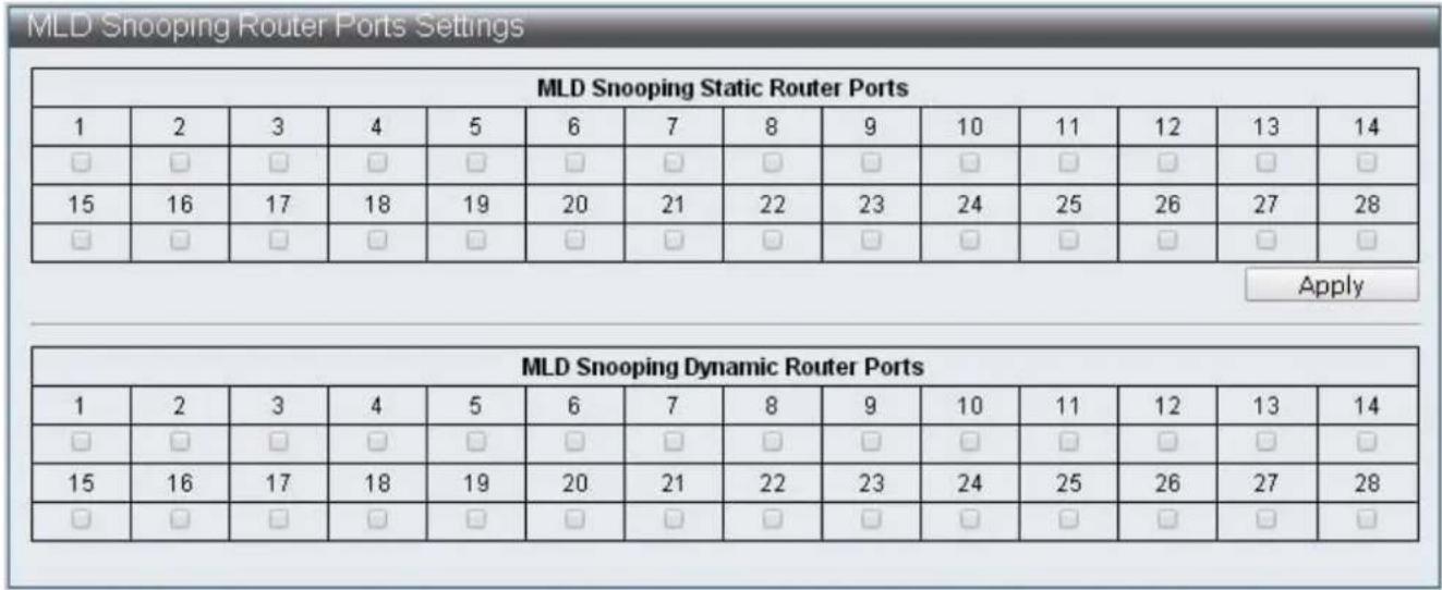
Figure 75 – Advanced Features > MLD Snooping > MLD Snooping Router Ports Sengs
| Item | Descripon |
| MLD Snooping Stac Router Ports | Stac Router Ports can be specied |
| MLD Snooping Dynamic Router Ports | Displays dynamic learning Router Ports |
IV-7-4-3 MLD Snooping Groups
To congure and display the MLD Snooping Groups, click Advanced Features > MLD Snooping > MLD Snooping Groups
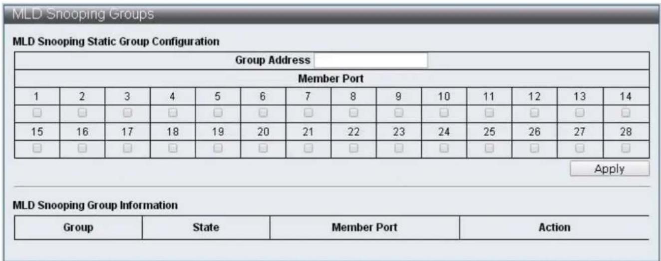
text_image
MLD Snooping Groups MLD Snooping Static Group Configuration Group Address Member Port 1 2 3 4 5 6 7 8 9 10 11 12 13 14 □ □ □ □ □ □ □ □ □ □ □ □ □ □ 15 16 17 18 19 20 21 22 23 24 25 26 27 28 □ □ □ □ □ □ □ □ □ □ □ □ □ □ Apply MLD Snooping Group Information Group State Member Port ActionFigure 76 – Advanced Features > MLD Snooping > MLD Snooping Groups
| Item | Descripon |
| MLD Snooping Stac Group Conguraon | Enable users to specify stac group and its member port |
| MLD Snooping Group Informaon | Display the all the currently existed Groups and their status |
IV-7-4-4 MLD Snooping Ports
To congure and display the MLD Snooping Ports, click Advanced Features > MLD Snooping > MLD Snooping Ports
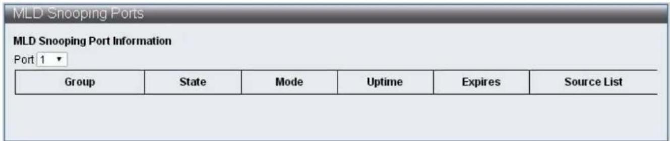
text_image
MLD Snooping Ports MLD Snooping Port Information Port 1 ▼ Group State Mode Uptime Expires Somcule ListFigure 77 – Advanced Features > MLD Snooping > MLD Snooping Ports
| Item | Descripon |
| MLD Snooping Port Informaon | Display the group and states of selected Ports |
IV-7-4-5 DHCP Relay Agent
To congure and display the DHCP Relay Agent, click Advanced Features > DHCP Relay Agent
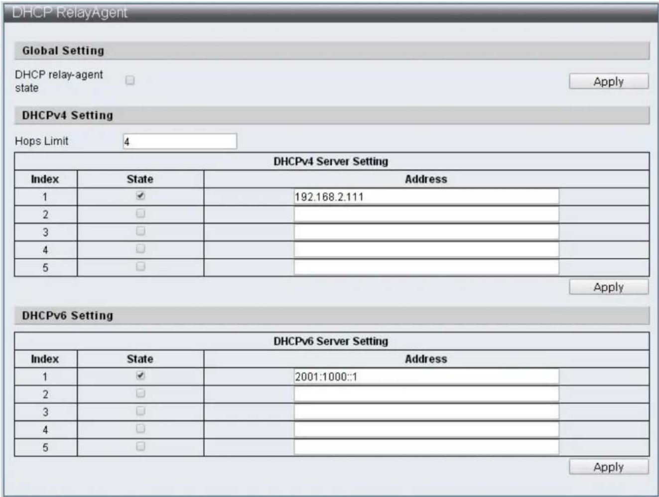
text_image
DHCP RelayAgent Global Setting DHCP relay-agent state Apply DHCPv4 Setting Hops Limit 4 DHCPv4 Server Setting Index State Address 1 ✓ 192.168.2.111 2 □ 3 □ 4 □ 5 □ Apply DHCPv6 Setting DHCPv6 Server Setting Index State Address 1 ✓ 2001:1000::1 2 □ 3 □ 4 □ 5 □ ApplyFigure 78 – Advanced Features >DHCP Relay Agent
| Item | Default | Descripon |
| DHCP relay-agent state | The switch of DHCP Relay-Agent | |
| Hops Limit | 4 | The number of mes DHCP packets can be forwarded |
| DHCPv4 Server Seng | DHCPv4 server seng, 5 groups can be specied | |
| DHCPv6 Server Seng | DHCPv6 server seng, 5 groups can be specied |
IV-7-5 Loop Detect
Loop Detect is able to detect the loops on the network of Switch, and then block 1 port of 2 ports that cause loop when it is detected, thus disable packets from entering Switch through the loop and prevent the conneccon failure by Switch.
To congure and display the Loop Detect, click Advanced Features > Loop Detect

text_image
Loop Detect Information Loop Detect Setting Loop Detection State Disable ▼ LDP Interval Time 3 , unit:500ms Block Release Time 9 , unit:500ms LDP MAC Destination Address 01:90:C3:00:00:00 Apply Loop Detect Port Setting Loop Detect Port Enabled 1 2 3 4 5 6 7 8 9 10 11 12 13 14 □ □ □ □ □ □ □ □ □ □ □ □ □ □ 15 16 17 18 19 20 21 22 23 24 25 26 27 28 □ □ □ □ □ □ □ □ □ □ □ □ □ □ Apply Loop Detect Port State Port (State 1 --- 2 --- 3 --- 4 --- 5 --- 6 --- 7 --- 8 --- RefreshFigure 79 – Advanced Features > Loop Detect
| Item | Descripon |
| Loop Detect State | Enable/Disable Loop Detect funcon |
| LDP Interval Time | Specify the interval me of sending loop detecon packets |
| Block Release Time | Specify the blocked Port and its release me |
| LDP MAC Desnaon Address | Specify DA that sends loop detecon packets |
| Loop Detect Port Enabled | Select Port with Loop Detect funcon enabled |
| Refresh | Refresh Loop Detect status |
IV-7-6 GVRP
The GARP VLAN Registraon Protocol (GVRP) is used to register and deregister VLAN aributes through message exchange between each Port. GVRP use messages are Join messages, Leave messages, and LeaveAll messages.
Join messages: When Switch receives Join messages from other devices or when it is congured with VLAN stacally, it sends Join messages to other devices.
Join messages are classied into JoinEmpty and JoinIn. JoinEmpty declares an unregistered aribute; JoinIn declares a registered aribute.
Leave messages: When switch receives Leave message from other devices or when some of its VLAN are deregistered stacally, it sends Leave messages to other devices. Leave messages are classied into LeaveEmpty and LeaveIn. LeaveEmpty deregisters an unregistered aribute; LeaveIn deregisters a registered aribute.
LeaveAll messages: When the Port enabled GVRP funcon, LeaveAll mer is also started. When the LeaveAll mer expires, the participant sends LeaveAll messages to other devices. LeaveAll deregisters all aributes to delete useless aributes on the network. GVRP mers are: Join mer, Leave mer and LeaveAll mer.
Join mer: The Join mer controls the sending of Join messages and ensures messages can be sent to other Switch. Join mer is enabled aer Join message is sent. If the JoinIn message is not received, it sends a second Join message when the Join mer expires. Leave mer: The Leave mer is used to control the sending of Leave messages. The Leave mer is started aer receiving a Leave or LeaveAll message. If other equipment does not receive any Join message of the corresponding aribute before the Leave mer expires, then such aribute is no longer in use and the Switch deregisters the aribute.
LeaveAll mer: When a Port starts GVRP funcon, it starts the LeaveAll mer. When the LeaveAll mer expires, the participant sends a LeaveAll message. The LeaveAll mer will restart aer receiving LeaveAll message to prevent generaon of unnecessary packets.
To congure and display the GVRP Sengs, click Advanced Features > GVRP Sengs
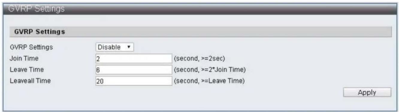
text_image
GVRP Settings GVRP Settings Disable Join Time 2 (second, >=2sec) Leave Time 6 (second, >=2*Join Time) LeaveAll Time 20 (second, >=Leave Time) ApplyFigure 80 – Advanced Features > GVRP Sengs
| Item | Descripon |
| GVRP Sengs | Enable/Disable GVRP funcons |
| Join Time | Specify Join mer, the minimum should not lower than 2 seconds |
| Leave Time | Specify Leave mer, the minimum should not lower than 2 mes of Join mer |
| Leaveall Time | Specify Leaveall mer, the minimum should not lower than Leave mer |
IV-7-7 Neighbor MACID
Neighbor MACID searches for neighboring Switch MAC ID of each Port. Then sends Neighbor Info packets according to the congured send period, Switch will add or update aging me of MAC ID aer receiving Neighbor Info packets. The use of UDP NetCmd tool may obtain the Switch Neighbor MAC ID informaon.
To congure and display the Neighbor MACID, click Advanced Features > Neighbor MACID
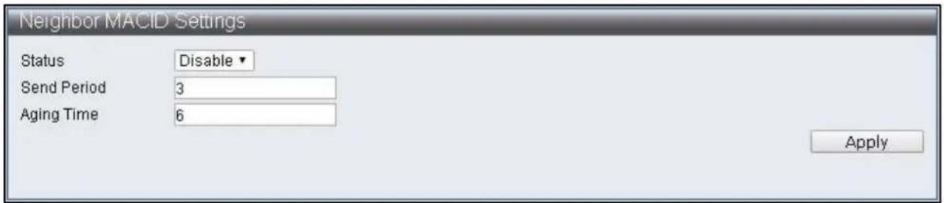
text_image
Neighbor MACID Settings Status Disable Send Period 3 Aging Time 6 ApplyFigure 81 – Advanced Features > Neighbor MACID
| Item | Descripon |
| Status | Enable/Disable Neighbor MACID funcons |
| Send Period | Specify the send period of Neighbor Info packets |
| Aging Time | Specify the data removal me of each MAC ID |
IV-8 Monitoring
IV-8-1 MIB Counter
MIB Counter is able to count the data volume received or transmied by each Port. The counting method of each Port can be further classified into 28 packet types received and 14 packets types transmied.
To congure and display the MIB Counter, click Monitoring > MIB Counter
| Port NO | Receive | Transmit | Action | |||
| Packets | Bytes | Packets | Bytes | |||
| 01 | 0 | 0 | 0 | 0 | Detail | |
| 02 | 0 | 0 | 0 | 0 | Detail | |
| 03 | 0 | 0 | 0 | 0 | Detail | |
| 04 | 0 | 0 | 0 | 0 | Detail | |
| 05 | 0 | 0 | 0 | 0 | Detail | |
| 06 | 0 | 0 | 0 | 0 | Detail | |
| 07 | 0 | 0 | 0 | 0 | Detail | |
| 08 | 0 | 0 | 0 | 0 | Detail | |
| 09 | 0 | 0 | 0 | 0 | Detail | |
| 10 | 0 | 0 | 0 | 0 | Detail | |
| 11 | 0 | 0 | 0 | 0 | Detail | |
| 12 | 0 | 0 | 0 | 0 | Detail | |
| 13 | 0 | 0 | 0 | 0 | Detail | |
| 14 | 0 | 0 | 0 | 0 | Detail | |
Figure 82 - Monitoring > MIB Counter
| Item | Descripon |
| Port No. | Port Number |
| Receive | Displays data of Packets and Bytes received |
| Transmit | Displays data of Packets and Bytes transmied |
| Acon | Provide more detailed data of the Port |
| Refresh | Refresh the data of Ports |
| Clear | Clear the data of Ports |
Monitoring > MIB Counter > Detail
| Type | Port 1 Counter | |
| Receive | Transmit | |
| 64b | 0 | 0 |
| 65-127b | 0 | 0 |
| 128-255b | 0 | 0 |
| 256-511b | 0 | 0 |
| 512-1023b | 0 | 0 |
| 1024-1518b | 0 | 0 |
| Oversize | 0 | 0 |
| Bcst | 0 | 0 |
| Mcst | 0 | 0 |
| Ucst | 0 | 0 |
| Pause | 0 | 0 |
| Pkts | 0 | 0 |
| Item | Descripon |
| Type | Type of packets |
| Receive | Display data received by dierent packet types |
| Transmit | Display data transmied by dierent packet types |
| Refresh | Refresh the data of Ports |
| Clear | Clear the data of Ports |
IV-8-2 Scan MACID Lookup Table
Scan MACID Lookup Table provide MAC Address of each Port and users can remove the MAC Address of Lookup Table.
To congure and display the Scan MACID Lookup Table, click Monitoring > Scan MACID Lookup Table
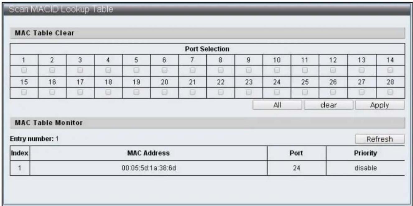
text_image
Scan MACID Lookup Table MAC Table Clear Port Selection 1 2 3 4 5 6 7 8 9 10 11 12 13 14 □ □ □ □ □ □ □ □ □ □ □ □ □ □ 15 16 17 18 19 20 21 22 23 24 25 26 27 28 □ □ □ □ □ □ □ □ □ □ □ □ □ □ All-clear Apply MAC Table Monitor Entry number: 1 Refresh Index MAC Address Port Priority 1 00:05:5d:1a:38:6d 24期間 disableFigure 83 – Monitoring > Scan MACID Lookup Table
| Item | Descripon |
| Port Selecon | Select default Port |
| All | Select all the Port |
| Clear | Clear the selected Port |
| Apply | Clear the MAC Table of default Port |
| Refresh | Refresh MAC Table |
IV-8-3 Syslog
Syslog displays applicaon log for managers.
To congure and display the Syslog, click Monitoring > Syslog
| Index | Log Message |
| 1 | Jan 1 00:00:20 sshd[198]: Server listening on 0.0.0.0 port 22. |
| 2 | Jan 1 00:00:20 sshd[198]: Server listening on 0.0.0.0 port 22. |
| 3 | Jan 1 00:00:23 misc_app[164]: Port 1 link up |
| 4 | Jan 1 00:00:24 misc_app[164]: Port 2 link up |
| 5 | Jan 1 00:00:24 misc_app[164]: Port 5 link up |
| 6 | Jan 1 00:00:24 misc_app[164]: Port 6 link up |
| 7 | Jan 1 00:00:24 kernel: eth0: no IPv6 routers present |
| 8 | Jan 1 00:00:24 misc_app[164]: Port 24 link up |
| 9 | Jan 1 00:00:24 klish[199]: (admin) startup : 0 |
| 10 | Jan 1 00:00:25 init: starting pid 247, tty ": '-/bin/sh' |
| 11 | Jan 1 08:16:43 klish[199]: (admin) enable DHCP_snooping : 0 |
| 12 | Jan 1 08:16:55 klish[199]: (admin) disable DHCP_snooping : 0 |
| 13 | Jan 1 08:16:59 mac_table.cgi[1439]: call static_entry function failed |
| 14 | Jan 1 08:17:00 mac_table.cgi[1439]: call static_entry function failed |
| 15 | Jan 1 08:17:25 mac_table.cgi[1501]: call static_entry function failed |
Figure 84 – Monitoring > Syslog
| Item | Descripon |
| Refresh | Refresh the log |
COPYRIGHT
Copyright © Edimax Technology Co., Ltd. all rights reserved. No part of this publicaon may be reproduced, transmied, transcribed, stored in a retrieval system, or translated into any language or computer language, in any form or by any means, electronic, mechanical, magnec, opcal, chemical, manual or otherwise, without the prior written permission from Edimax Technology Co., Ltd.
Edimax Technology Co., Ltd. makes no representaons or warranes, either expressed or implied, with respect to the contents hereof and specifically disclaims any warranes, merchantability, or tness for any parcular purpose. Any soware described in this manual is sold or licensed as is. Should the programs prove defecve following their purchase, the buyer (and not this company, its distributor, or its dealer) assumes the enre cost of all necessary servicing, repair, and any incidental or consequential damages resulting from any defect in the soware. Edimax Technology Co., Ltd. reserves the right to revise this publicaon and to make changes from me to me in the contents hereof without the obligaon to nofy any person of such revision or changes.
The product you have purchased and the setup screen may appear slightly dierent from those shown in this QIG. The soware and specicaons are subject to change without noce. Please visit our website www.edimax.com for updates. All brand and product names menoned in this manual are trademarks and/or registered trademarks of their respective holders.
Federal Communicaon Commission Interference Statement
This equipment has been tested and found to comply with the limits for a Class B digital device, pursuant to Part 15 of FCC Rules. These limits are designed to provide reasonable protecon against harmful interference in a residential installaon. This equipment generates, uses, and can radiate radio frequency energy and, if not installed and used in accordance with the instrucons, may cause harmful interference to radio communicaons. However, there is no guarantee that interference will not occur in a parcular installaon. If this equipment does cause harmful interference to radio or television recepon, which can be determined by turning the equipment o and on, the user is encouraged to try to correct the interference by one or more of the following measures:
- Reorient or relocate the receiving antenna.
- Increase the separaon between the equipment and receiver.
- Connect the equipment into an outlet on a circuit dierent from that to which the receiver is connected.
- Consult the dealer or an experienced radio technician for help.
FCC Cauon
This device and its antenna must not be co-located or operang in conjuncon with any other antenna or transmier. This device complies with Part 15 of the FCC Rules. Operaon is subject to the following two conditions: (1) this device may not cause harmful interference, and (2) this device must accept any interference received, including interference that may cause undesired operaon. Any changes or modicaons not expressly approved by the party responsible for compliance could void the authority to operate equipment.
Federal Communicaons Commission (FCC) Radiaon Exposure Statement
This equipment complies with FCC radiaon exposure set forth for an uncontrolled environment. In order to avoid the possibility of exceeding the FCC radio frequency exposure limits, human proximity to the antenna shall not be less than 2.5cm (1 inch) during normal operaon.
Federal Communicaons Commission (FCC) RF Exposure Requirements
This EUT is compliance with SAR for general population/uncontrolled exposure limits in ANSI/IEEE C95.1-1999 and had been tested in accordance with the measurement methods and procedures specified in OET Bullen 65 Supplement C. The equipment version marketed in US is restricted to usage of the channels 1-11 only. This equipment is restricted to indoor use when operated in the 5.15 to 5.25 GHz frequency range.
R&TTE Compliance Statement
This equipment complies with all the requirements of DIRECTIVE 2014/30/EU OF THE EUROPEAN PARLIAMENT AND THE COUNCIL of March 9, 1999 on radio equipment and telecommunicaon terminal equipment and the mutual recognition of their conformity (R&TTE). The R&TTE Direcve repeals and replaces in the direcve 98/13/EEC (Telecommunicaons Terminal Equipment and Satellite Earth Staon Equipment) As of April 8, 2000.
Safety
This equipment is designed with the utmost care for the safety of those who install and use it. However, special aenon must be paid to the dangers of electric shock and stac electricity when working with electrical equipment. All guidelines of this and of the computer manufacture must therefore be allowed at all mes to ensure the safe use of the equipment.
EU Countries Intended for Use
The ETSI version of this device is intended for home and oce use in Austria, Belgium, Bulgaria, Cyprus, Czech, Denmark, Estonia, Finland, France, Germany, Greece, Hungary, Ireland, Italy, Latvia, Lithuania, Luxembourg, Malta, Netherlands, Poland, Portugal, Romania, Slovakia, Slovenia, Spain, Sweden, Turkey, and United Kingdom. The ETSI version of this device is also authorized for use in EFTA member states: Iceland, Liechtenstein, Norway, and Switzerland.
EU Countries Not Intended for Use
None
EU Declaraon of Conformity
English: This equipment is in compliance with the essenal requirements and other relevant provisions of Direcve 2014/30/EU.
WEEE Directive & Product Disposal

At the end of its serviceable life, this product should not be treated as household or general waste. It should be handed over to the applicable collecon point for the recycling of electrical and electronic equipment, or returned to the supplier for disposal.
Declaraon of Conformity
We, Edimax Technology Co., Ltd., declare under our sole responsibility, that the equipment described below complies with the requirements of the European R&TTE directives.
Equipment: 24-port FE Smart Switch + 4 Combo GbE Ports w/ 24 PoE+ ports Model No.: ES-5424P
The following European standards for essenal requirements have been followed:
Directives 2014/30/EU
EMC : EN 55032:2015
EN 61000-3-2:2014 Class A
EN 61000-3-3:2013
EN 55035:2017
Safety (LVD) : EN 60950-1:2006 + A11:2009 + A1:2010 + A12:2011+A2:2013
Edimax Technology Europe B.V. a company of :
Fijenhof 2, Edimax Technology Co., Ltd.
5652 AE Eindhoven, No. 278, Xinhu 1st Rd.,
The Netherlands Neihu Dist., Taipei City,
Taiwan
Signature:
Printed Name: Vivian Ma
Title: Director
Edimax Technology Europe B.V.

Date of Signature: Aug., 2018
Signature:

Printed Name: Albert Chang
Title: Director
Edimax Technology Co., Ltd.
Noce According to GNU General Public License Version 2
This product includes soware that is subject to the GNU General Public License version 2. The program is free soware and distributed without any warranty of the author. We oer, valid for at least three years, to give you, for a charge no more than the costs of physically performing source distribuon, a complete machine-readable copy of the corresponding source code.
Version 2, June 1991
Copyright (C) 1989, 1991 Free Soware Foundaon, Inc. 51 Franklin Street, Fih Floor, Boston, MA 02110-1301, USA Everyone is permitted to copy and distribute verbam copies of this license document, but changing it is not allowed.
Preamble
The licenses for most soware are designed to take away your freedom to share and change it. By contrast, the GNU General Public License is intended to guarantee your freedom to share and change free soware--to make sure the soware is free for all its users. This General Public License applies to most of the Free Soware Foundaon's soware and to any other program whose authors commit to using it. (Some other Free Soware Foundaon soware is covered by the GNU Lesser General Public License instead.) You can apply it to your programs, too.
When we speak of free soware, we are referring to freedom, not price. Our General Public Licenses are designed to make sure that you have the freedom to distribute copies of free soware (and charge for this service if you wish), that you receive source code or can get it if you want it, that you can change the soware or use pieces of it in new free programs; and that you know you can do these things.
To protect your rights, we need to make restricons that forbid anyone to deny you these rights or to ask you to surrender the rights. These restricons translate to certain responsibilities for you if you distribute copies of the soware, or if you modify it.
For example, if you distribute copies of such a program, whether gras or for a fee, you must give the recipients all the rights that you have. You must make sure that they, too, receive or can get the source code. And you must show them these terms so they know their rights.
We protect your rights with two steps: (1) copyright the soware, and (2) oer you this license which gives you legal permission to copy, distribute and/or modify the soware.
Also, for each author's protecon and ours, we want to make certain that everyone understands that there is no warranty for this free soware. If the soware is modified by someone else and passed on, we want its recipients to know that what they have is not the original, so that any problems introduced by others will not react on the original authors' reputaons.
Finally, any free program is threatened constantly by soware patents. We wish to avoid the danger that redistributors of a free program will individually obtain patent licenses, in eect making the program proprietary. To prevent this, we have made it clear that any patent must be licensed for everyone's free use or not licensed at all.
The precise terms and conditions for copying, distribuon and modicaon follow.
TERMS AND CONDITIONS FOR COPYING, DISTRIBUTION AND MODIFICATION
- This License applies to any program or other work which contains a noce placed by the copyright holder saying it may be distributed under the terms of this General Public License. The “Program”, below, refers to any such program or work, and a “work based on the Program” means either the Program or any derivative work under copyright law: that is to say, a work containing the Program or a poron of it, either verbam or with modicaons and/or translated into another language. (Hereinaer, translaon is included without limitaon in the term “modicaon”.) Each licensee is addressed as “you”.
Acvies other than copying, distribuon and modicaon are not covered by this License; they are outside its scope. The act of running the Program is not restricted, and the output from the Program is covered only if its contents constute a work based on the Program (independent of having been made by running the Program). Whether that is true depends on what the Program does.
- You may copy and distribute verbam copies of the Program's source code as you receive it, in any medium, provided that you conspicuously and appropriately publish on each copy an appropriate copyright noce and disclaimer of warranty; keep
intact all the noces that refer to this License and to the absence of any warranty; and give any other recipients of the Program a copy of this License along with the Program.
You may charge a fee for the physical act of transferring a copy, and you may at your opon oer warranty protecon in exchange for a fee.
- You may modify your copy or copies of the Program or any poron of it, thus forming a work based on the Program, and copy and distribute such modicaons or work under the terms of Secon 1 above, provided that you also meet all of these conditions:
a) You must cause the modified les to carry prominent noces stang that you changed the les and the date of any change.
b) You must cause any work that you distribute or publish, that in whole or in part contains or is derived from the Program or any part thereof, to be licensed as a whole at no charge to all third pares under the terms of this License.
c) If the modified program normally reads commands interactively when run, you must cause it, when started running for such interactive use in the most ordinary way, to print or display an announcement including an appropriate copyright notice and a notice that there is no warranty (or else, saying that you provide a warranty) and that users may redistribute the program under these conditions, and telling the user how to view a copy of this License. (Excepon: if the Program itself is interactive but does not normally print such an announcement, your work based on the Program is not required to print an announcement.)
These requirements apply to the modified work as a whole. If idenable seconds of that work are not derived from the Program, and can be reasonably considered independent and separate works in themselves, then this License, and its terms, do not apply to those seconds when you distribute them as separate works. But when you distribute the same seconds as part of a whole which is a work based on the Program, the distribution of the whole must be on the terms of this License, whose permissions for other licensees extend to the entire whole, and thus to each and every part regardless of who wrote it.
Thus, it is not the intent of this secon to claim rights or contest your rights to work wrien enrely by you; rather, the intent is to exercise the right to control the distribuon of derivave or collecve works based on the Program.
In addition, mere aggregaon of another work not based on the Program with the Program (or with a work based on the Program) on a volume of a storage or distribuon medium does not bring the other work under the scope of this License.
- You may copy and distribute the Program (or a work based on it, under Secon 2) in object code or executable form under the terms of Secons 1 and 2 above provided that you also do one of the following:
a) Accompany it with the complete corresponding machine-readable source code, which must be distributed under the terms of Secons 1 and 2 above on a medium customarily used for soware interchange; or,
b) Accompany it with a wrien oer, valid for at least three years, to give any third party, for a charge no more than your cost of physically performing source distribuon, a complete machine-readable copy of the corresponding source code, to be distributed under the terms of Secons 1 and 2 above on a medium customarily used for soware interchange; or,
c) Accompany it with the informaon you received as to the oer to distribute corresponding source code. (This alternate is allowed only for noncommercial distribuon and only if you received the program in object code or executable form with such an oer, in accord with Subsecon b above.)
The source code for a work means the preferred form of the work for making modicaons to it. For an executable work, complete source code means all the source code for all modules it contains, plus any associated interface denion les, plus the scripts used to control compilaon and installaon of the executable. However, as a special exception, the source code distributed need not include anything that is normally distributed (in either source or binary form) with the major components (compiler, kernel, and so on) of the operang system on which the executable runs, unless that component itself accompanies the executable.
If distribuon of executable or object code is made by oering access to copy from a designated place, then oering equivalent access to copy the source code from the same place counts as distribuon of the source code, even though third pares are not compelled to copy the source along with the object code.
-
You may not copy, modify, sublicense, or distribute the Program except as expressly provided under this License. Any aempt otherwise to copy, modify, sublicense or distribute the Program is void, and will automatically terminate your rights under this License. However, pares who have received copies, or rights, from you under this License will not have their licenses terminated so long as such pares remain in full compliance.
-
You are not required to accept this License, since you have not signed it. However, nothing else grants you permission to modify or distribute the Program or its derivative works. These acons are prohibited by law if you do not accept this License.
Therefore, by modifying or distribung the Program (or any work based on the Program), you indicate your acceptance of this License to do so, and all its terms and conditions for copying, distribung or modifying the Program or works based on it.
-
Each me you redistribute the Program (or any work based on the Program), the recipient automacally receives a license from the original licensor to copy, distribute or modify the Program subject to these terms and conditions. You may not impose any further restricons on the recipients' exercise of the rights granted herein. You are not responsible for enforcing compliance by third pares to this License.
-
If, as a consequence of a court judgment or allegaon of patent infringement or for any other reason (not limited to patent issues), condions are imposed on you (whether by court order, agreement or otherwise) that contradict the conditions of this License, they do not excuse you from the conditions of this License. If you cannot distribute so as to sasfy simultaneously your obligaons under this License and any other pernent obligaons, then as a consequence you may not distribute the Program at all. For example, if a patent license would not permit royalty-free redistribution of the Program by all those who receive copies directly or indirectly through you, then the only way you could sasfy both it and this License would be to refrain enrely from distribution of the Program.
If any poron of this secon is held invalid or unenforceable under any parcular circumstance, the balance of the secon is intended to apply and the secon as a whole is intended to apply in other circumstances.
It is not the purpose of this secon to induce you to infringe any patents or other property right claims or to contest validity of any such claims; this secon has the sole purpose of protecng the integrity of the free soware distribuon system, which is implemented by public license pracces. Many people have made generous contribuons to the wide range of soware distributed through that system in reliance on consistent applicaon of that system; it is up to the author/donor to decide if he or she is willing to distribute soware through any other system and a licensee cannot impose that choice.
This secon is intended to make thoroughly clear what is believed to be a consequence of the rest of this License.
-
If the distribuon and/or use of the Program is restricted in certain countries either by patents or by copyrighted interfaces, the original copyright holder who places the Program under this License may add an explicit geographical distribuon limitaon excluding those countries, so that distribuon is permied only in or among countries not thus excluded. In such case, this License incorporates the limitaon as if written in the body of this License.
-
The Free Soware Foundaon may publish revised and/or new versions of the General Public License from me to me. Such new versions will be similar in spirit to the present version, but may differ in detail to address new problems or concerns.
Each version is given a disguishing version number. If the Program species a version number of this License which applies to it and “any later version”, you have the opon of following the terms and condions either of that version or of any later version published by the Free Soware Foundaon. If the Program does not specify a version number of this License, you may choose any version ever published by the Free Soware Foundaon.
- If you wish to incorporate parts of the Program into other free programs whose distribuon conditions are dierent, write to the author to ask for permission. For soware which is copyrighted by the Free Soware Foundation, write to the Free Soware Foundaon; we somemes make excepons for this. Our decision will be guided by the two goals of preserving the free status of all derivatives of our free soware and of promong the sharing and reuse of soware generally.
NO WARRANTY
-
BECAUSE THE PROGRAM IS LICENSED FREE OF CHARGE, THERE IS NO WARRANTY FOR THE PROGRAM, TO THE EXTENT PERMITTED BY APPLICABLE LAW. EXCEPT WHEN OTHERWISE STATED IN WRITING THE COPYRIGHT HOLDERS AND/OR OTHER PARTIES PROVIDE THE PROGRAM "AS IS" WITHOUT WARRANTY OF ANY KIND, EITHER EXPRESSED OR IMPLIED, INCLUDING, BUT NOT LIMITED TO, THE IMPLIED WARRANTIES OF MERCHANTABILITY AND FITNESS FOR A PARTICULAR PURPOSE. THE ENTIRE RISK AS TO THE QUALITY AND PERFORMANCE OF THE PROGRAM IS WITH YOU. SHOULD THE PROGRAM PROVE DEFECTIVE, YOU ASSUME THE COST OF ALL NECESSARY SERVICING, REPAIR OR CORRECTION.
-
IN NO EVENT UNLESS REQUIRED BY APPLICABLE LAW OR AGREED TO IN WRITING WILL ANY COPYRIGHT HOLDER, OR ANY OTHER PARTY WHO MAY MODIFY AND/OR REDISTRIBUTE THE PROGRAM AS PERMITTED ABOVE, BE LIABLE TO YOU FOR DAMAGES, INCLUDING ANY GENERAL, SPECIAL, INCIDENTAL OR CONSEQUENTIAL DAMAGES ARISING OUT OF THE USE OR INABILITY TO USE THE PROGRAM (INCLUDING BUT NOT LIMITED TO LOSS OF DATA OR DATA BEING RENDERED INACCURATE OR LOSSES SUSTAINED BY YOU OR THIRD PARTIES OR A FAILURE OF THE PROGRAM TO OPERATE WITH ANY OTHER PROGRAMS), EVEN IF SUCH HOLDER OR OTHER PARTY HAS BEEN ADVISED OF THE POSSIBILITY OF SUCH DAMAGES.